JP3960165B2 - Shift control device for continuously variable transmission - Google Patents
Shift control device for continuously variable transmission Download PDFInfo
- Publication number
- JP3960165B2 JP3960165B2 JP2002245210A JP2002245210A JP3960165B2 JP 3960165 B2 JP3960165 B2 JP 3960165B2 JP 2002245210 A JP2002245210 A JP 2002245210A JP 2002245210 A JP2002245210 A JP 2002245210A JP 3960165 B2 JP3960165 B2 JP 3960165B2
- Authority
- JP
- Japan
- Prior art keywords
- speed
- gear ratio
- reverse
- shift
- ratio
- Prior art date
- Legal status (The legal status is an assumption and is not a legal conclusion. Google has not performed a legal analysis and makes no representation as to the accuracy of the status listed.)
- Expired - Fee Related
Links
Images


Description
【0001】
【発明の属する技術分野】
本発明は、無段変速機の変速制御装置、特に後進時における変速比制御に関する。
【0002】
【従来の技術】
前進時と後進時とで、異なる変速制御油圧系を有するトロイダル型無段変速機(以下、TCVTと記載する)の後進時制御技術として、特開平8−93873号に記載のものが知られている。この公報には、後進時の変速制御油圧系の故障時や、後進時に間違って前進側の変速制御油圧系を用いた場合に用いられる。このとき、前進時の変速制御を用いて、変速比が増速側に変速するように算出した駆動指令値を、変速アクチュエータに指令する。TCVTは、前進時と後進時とにおいて、トラニオンのオフセットに対する変速方向が異なるため、このときTCVTは減速側に変速する。これにより、減速側の変速比による発進が確保できる。
【0003】
ここで、前後進で異なる変速制御油圧系を用いる理由を述べる。トラニオンのオフセットに対する傾転角度(変速比)の特性は不安定である。このため、TCVTは、変速アクチュエータ変位に応じて前記油圧アクチュエータへ油を供給する変速制御弁と機械的に連結したプリセスカムを備え、傾転角度とトラニオン変位を、プリセスカムを介して変速制御弁にフィードバックして、変速アクチュエータ変位に対する傾転角度の特性を機械的に安定化する変速制御油圧系を有する。但し、前進時と後進時とでは、入出力ディスクの回転方向が異なるため、トラニオンの上下方向オフセットに対する傾転方向も異なる。これに応じて、前進時と後進時とで、極性の異なる変速制御油圧系を設け、前後進で切り換えて用いる。
【0004】
また、変速アクチュエータの大型化を防ぎながら、変速アクチュエータを安定に駆動する従来技術として、特開平8−178042号公報に記載の技術が知られている。TCVTでは、運転状態に適応した好適な目標変速比を演算し、これに対応した変速指令により、モータなどの変速アクチュエータを変位させて、変速制御弁を目標変速比に対応したストローク位置に操作するよう構成する。この操作により該変速制御弁は目標変速比に対応した変速制御圧を作り出し、TCVTは当該変速制御圧に応動して目標変速比に向け無段階に変速される。しかし、無段変速機の作動油は温度に応じて粘度が変化し、低温で高粘度になる。加えて、通常はアルミニウムで造る変速制御弁のバルブボディと、通常は鉄で造る変速制御弁のスプールとの間のクリアランスが、低温時ほど小さくなる。これらの理由から、作動油温が低温である時、変速制御弁をストロークさせる時の粘性抵抗が大きくなり、変速制御弁をストロークさせる変速アクチュエータの要求駆動力が低温時は大きくなり、変速制御弁をストロークさせる変速アクチュエータの要求駆動力が低温時は大きくなる。ここで、同じ作動油温(変速制御弁の粘性抵抗が同じ状態)のもとでも、変速アクチュエータ駆動速度を遅くすれば変速アクチュエータの要求駆動力が小さくなるとの観点から、このモータ駆動速度を変速機作動油温に応じて制御することで、変速アクチュエータの要求駆動力が低温時も大きくなることのないようにし、もって変速アクチュエータの大型化を防止している。
【0005】
【発明が解決しようとする課題】
しかしながら、上記特開平8−93873号公報には、駆動指令値を増速側に大きくすると(後進時、ユニットは減速側に変速する)、これに応じてトラニオンのオフセットも大きくなる。このため、駆動指令値を増速側に大きくしすぎると、トラニオンがオフセット方向のストッパ(具体的には、トラニオンの軸方向変位アクチュエータであるサーボピストンのピストンシリンダ)に接触する可能性がある。これによる影響の1つとして、トラニオンがストッパに強い力で押しつけられながら傾転することにより、トラニオンとストッパとの接触部分(具体的にはピストンやシリンダ)が摩耗する可能性がある。また、複数個のパワーローラを有する場合、オフセットのストッパ位置は、加工精度のバラツキにより一定ではない。このバラツキのため、ストッパに接触している状態では、それぞれのトラニオンのオフセット量が異なり、傾転速度がそれぞれ異なる。これにより、トラニオンが傾転角度のストッパに接触するまでの過渡時において、それぞれの傾転角度が一緒にならず、それぞれのパワーローラ接触点におけるディスクとパワーローラとの滑りが大きくなる。この滑りが、摩耗や発熱を発生させる可能性がある。以上の摩耗や発熱が、トロイダル伝導ユニットの耐久性を落とす可能性がある。
【0006】
また、後進側の変速制御油圧系を持たず、前進側の変速制御油圧系を後進側でも兼用するTCVTの後進時において、フィードバック制御で目標変速比と変速比との偏差が補償できないときも、特開平8−93873号の技術は適用できる。この場合も上記と同様の問題が発生する虞がある。
【0007】
このフィードバック制御で目標変速比と変速比との偏差が補償できない状況は、後進時、変速比を検出するセンサの異常などで、変速比の検出ができなくなった場合や、特開平8−178042号公報で記載されているように、油温に応じて変速アクチュエータの速度を小さくした場合などに起こりえる可能性がある。このように、フィードバック制御で前記偏差が補償できないとき、変速比は減速側もしくは増速側に変速する。減速側に変速する場合、一般的に後進時の目標変速比が最減速比付近であることと、駆動力が増える方向であるため問題は少ない。一方、増速側に変速する場合、駆動力が減る方向であり発進時に希望の加速感が得られなくなる可能性がある。
【0008】
本発明は、上記問題点に着目してなされたもので、その目的とするところは、無段変速機の耐久性の向上を図りつつ、後進時においても安定した変速制御が可能な無段変速機の変速制御装置を提供することを目的とする。
【0009】
上記課題を解決するために、本発明では、同軸配置した入出力ディスク間で油の剪断力により動力伝達を行うパワーローラを背面支持するトラニオンを備え、該トラニオンを油圧アクチュエータによりトラニオンの傾転軸方向へオフセットさせることでトラニオンを傾転させ、パワーローラと入出力ディスクとの接点を移動させることにより無段変速を行うトロイダル伝導ユニットと、前記トロイダル伝導ユニットと駆動源との間に配置された前後進切換装置と、前記オフセットに対して車両の前進時と車両の後進時とにおける前記トラニオンの傾転方向の違いを補正して、前進時において変速アクチュエータに対する変速比の特性が安定となるように、前記油圧アクチュエータへ油を供給し、前進時と後進時とで変速制御油圧系を兼用した変速制御油圧系と、を備えた無段変速機の変速制御装置において、目標変速比を設定する目標変速比設定手段と、変速比を検出または推定する変速比検出手段と、車両の前後進を検出または推定する前後進検出手段と、前記変速アクチュエータの最大駆動速度を推定する駆動速度推定手段と、検出された変速比を電子的にフィードバックして、前記目標変速比と前記変速比との偏差に応じて、該偏差を補償するように変速アクチュエータの駆動指令値を演算する通常時制御手段と、前記目標変速比と前記変速比との偏差の補償が、前記通常時制御手段により補償可能かどうかを判断する補償判断手段と、該補償判断手段により前記偏差の補償ができないと判断したときは、変速アクチュエータの駆動指令値を、変速比が減速側に変速すると共に、トラニオン変位がトラニオンオフセット方向のストッパに当たらない値とする異常時制御手段と、を設け、前記補償判断手段は、後進が検出され、かつ、変速アクチュエータの最大駆動速度が所定値以下の時は、目標変速比と変速比との偏差が補償できないと判断し、前記異常時制御手段で演算する変速アクチュエータの駆動指令値は、後進時に、変速比が減速側に変速すると共に、トラニオンがトラニオンオフセット方向のストッパに当たらない値とすることを特徴とすることで上記課題を解決した。
【0010】
【発明の効果】
本発明では、走行環境の変化によってステップモータの駆動速度が保証できない場合であっても、ロー変速比によるリバース発進が可能となると共に、トラニオンやパワーローラ及び入出力ディスクの摩耗や発熱を抑制することが可能となり、無段変速機の耐久性の向上を図ると共に、安定した変速制御を達成することができる。
【0011】
【発明の実施の形態】
(実施の形態1)
【0012】
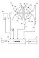
図1は本発明の実施の形態1におけるトロイダル型無段変速機10(以下TCVTと記載する)のスケルトン図を示し、図2はTCVT10の断面、および変速制御系の構成を示すものである。
【0013】
図1中左側に設けられる動力源としての図外のエンジン回転が、トルクコンバータ12を介してTCVT10に入力される。このトルクコンバータ12は、一般によく知られるように、ポンプインペラ12a、タービンランナ12bおよびステータ12cを備え、特に本実施の形態1のトルクコンバータ12ではロックアップクラッチ12dが設けられている。また、トルクコンバータ12の出力回転軸14と同軸上に配置されるトルク伝達軸16が設けられ、該トルク伝達軸16に第1トロイダル変速部18と第2トロイダル変速部20とがタンデム配置されている。
【0014】
これら第1,第2トロイダル変速部18,20は、それぞれの対向面がトロイド曲面に形成される一対の第1入力ディスク18a,第1出力ディスク18bおよび第2入力ディスク20a,第2出力ディスク20bと、これら第1入出力ディスク18a,18bおよび第2入出力ディスク20a,20bのそれぞれの対向面間に摩擦接触されるパワーローラ18c,18dおよび20c,20dとによって構成される。
【0015】
第1トロイダル変速部18は、トルク伝達軸16の図中左方に配置されると共に、第2トロイダル変速部20は、トルク伝達軸16の図中右方に配置され、かつ、それぞれの第1入力ディスク18aおよび第2入力ディスク20bは互いに内側に配置されている。
【0016】
一方、第1,第2出力ディスク18b,20bは、トルク伝達軸16に相対回転可能に嵌合された出力ギア28にスプライン嵌合され、第1,第2出力ディスク18b,20bに伝達された回転力は、この出力ギア28及びこれに噛合される入力ギア30aを介してカウンターシャフト30に伝達され、更に、回転力出力経路を介して図外の出力軸に伝達される。
【0017】
第1入力ディスク18aの外側にはローディングカム装置34が設けられている。このローディングカム装置34には、前後進切換装置40を介してトルクコンバータ12の出力回転が入力され、この入力トルクに応じた押付力がローディングカム装置34によって発生されるようになっている。尚、ローディングカム装置34のローディングカム34aは、トルク伝達軸16に相対回転可能に嵌合されると共に、スラストベアリング36を介してトルク伝達軸16に係止される。
【0018】
また、第2入力ディスク20aとトルク伝達軸16の図中右方端部との間に皿ばね38が設けられている。従って、ローディングカム装置34で発生される押圧力は、第1入力ディスク18aに作用すると共に、トルク伝達軸16及び皿ばね38を介して第2入力ディスク20aにも作用し、かつ、皿ばね38によって発生される予圧力は、第2入力ディスク20aに作用すると共に、トルク伝達軸16およびローディングカム装置34を介して第1入力ディスク18aにも作用するようになっている。
【0019】
前後進切換装置40は、ダブルピニオン方式の遊星歯車機構42と、この遊星歯車機構42のキャリア42aを出力回転軸14に締結可能なフォワードクラッチ44と、遊星歯車機構42のリングギア42bをハウジング22に締結可能なリバースブレーキ46とによって構成されている。
【0020】
前後進切換装置40では、フォワードクラッチ44を締結すると共に、リバースブレーキ46を解放することにより、エンジン回転と同方向の回転がTCVT10に入力され、かつ、フォワードクラッチ44を解放してリバースブレーキ46を締結することにより、逆方向の回転が入力されるようになっている。
【0021】
第1トロイダル変速部18および第2トロイダル変速部20に設けられたパワーローラ18c,18d及び20c,20dは、中心軸Cに対称に配置されている。そして、それぞれのパワーローラは変速制御装置としての変速制御弁56及び油圧アクチュエータ50を介して、車両運転条件に応じて傾転され、これにより第1,第2入力ディスク18a,20aの回転を無段階に変速して第1,第2出力ディスク18b,20bに伝達する。
【0022】
図2はTCVT10の変速制御を行う油圧系の機械的構成図である。パワーローラ20cはトラニオン23により背面から支持されている。トラニオン23は油圧サーボ50のサーボピストン51と連結しており、油圧サーボ50内のシリンダ50a内の油と50b内の油の差圧により軸方向に変位する。
【0023】
シリンダ50a,50bは、それぞれシフトコントロールバルブ56のHi側ポート56HiとLow側ポート56Lowに接続されている。このシフトコントロールバルブ56はバルブ内のスプール56Sが変位することにより、ライン圧をHi側ポート56Hi又はLow側ポート56Lowに流し、他方のポートからドレーン56Dへ油を流出させることで油圧サーボ内の差圧を変化させる。スプール56Sは、ステップモータ52及び後述するプリセスカム55とリンク構造で連結している。
【0024】
プリセスカム55は、4体のトラニオンのうち1体に取り付けられており、パワーローラ20aの上下方向変位とパワーローラの傾転角度をリンクの変位に変換する。スプール56Sの変位は、ステップモータ変位とプリセスカム55で伝えられる(フィードバックされる)変位により決定される。
【0025】
TCVT10は、トラニオン23を平衡点から上下に変位させることにより、パワーローラ20cと入出力ディスク20a,20bの回転方向ベクトルに差異が発生し、このベクトル差によって傾転することで変速する。変速の定常時には、パワーローラ20c及びトラニオン23の変位は平衡点に戻り、スプール56Sの変位も中立点でバルブが閉じた状態となっている。また、複数のトラニオン23には、それぞれ傾転角を規制する傾転ストッパ24が設けられている。これにより、パワーローラの過度の傾転を防止している。
【0026】
前進時において、プリセスカム55は、パワーローラ20cの傾転角度をスプール56Sの変位に負帰還し、傾転角度の目標値とのズレを補償する。また、同時にパワーローラ20c及びトラニオン23の平衡点からの変位もスプール56Sの変位に負帰還する。これにより、変速過渡状態においてダンピングの効果を与え、変速のハンチングを抑制している。
【0027】
ここで、変速の到達点はステップモータ52の変位で決まるものであり、その一連の変速過程を以下に示す。ステップモータ変位を変化させることでスプール56Sが変位してバルブが開く。これによりサーボピストン51の差圧が変化することでトラニオン23が平衡点から軸方向に変位することでパワーローラが傾転する。パワーローラの傾転角度がステップモータ変位に対応した時点でスプール56Sは中立点に戻り変速が終了する。
【0028】
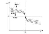
一方、後進時においては、パワーローラの上下方向変位に対する傾転方向が、前進時とは異なる。これにより、プリセスカム55は、パワーローラ20cの傾転角度をスプール56Sの変位に正帰還することによるので、後進時において、傾転角度がステップモータ変位に対応した点で平衡せず、ステップモータ変位に対する傾転角度の特性は不安定となる。
【0029】
図3は、変速制御装置を備えたTCVT10の構成図である。上述したように、実施の形態1の機械的構成では、後進時、ステップモータ変位に対する傾転角度の特性は不安定となる。このため、変速比の電子的フィードバック制御を用いて、変速比を制御する。入力ディスク回転数センサ84は、入力ディスク18a,21aの何れか1つの回転に同期して発生するパルス信号を、周期計測もしくは周波数計測して入力ディスク回転数を検出する。出力ディスク回転数センサ83は、出力ディスク18b,21bの何れか1つの回転に同期して発生するパルス信号を、周期計測もしくは周波数計測して出力ディスク回転数を検出する。
【0030】
アクセル踏み込み量センサ81は、ロータリエンコーダ等を用いてアクセル踏み込み量を検出する。入力軸トルクセンサ87は、トルクセンサを用いて入力軸トルクを検出する。油温センサ89は、温度センサを用いて油温を検出する。
【0031】
マイクロコンピュータを主体に構成された変速制御装置80は、入力ディスク回転数と、出力ディスク回転数と、アクセル踏み込み量と、入力軸トルクと、油温とを入力して、ステップモータ52の指令値を演算する。
【0032】
図4は変速制御装置80において実行される変速制御を表すブロック図である。目標変速比設定手段100では、車速VSPとアクセル踏み込み量APSとから目標変速比G*を演算する。まず、車速VSPとアクセル踏み込み量APSとから、図5に示すマップを用いて、到達エンジン回転数ωteを求める。ここで、車速VSPは、出力ディスク回転数ωodと車速VSPとの関係を示す下記の式1を用いて、出力ディスク回転数ωodから算出する。
(式1)
![]()
【0033】
次に、到達エンジン回転数ωteと出力ディスク回転数ωodとから、式(2)に示す関係を用いて到達CVT変速比Gtを算出する。
(式2)

最後に、到達CVT変速比Gtから、例えば式(3)に示すローパスフィルタを用いて目標変速比G*を算出する。
(式3)
【0035】
変速比検出手段101では、例えば入力ディスク回転数ωidの検出値と出力ディスク回転数ωodの検出値とから式(4)に示す関係を用いて変速比検出値を算出する。
(式4)
通常制御手段103では、目標変速比G*と変速比Gとを入力し、変速比が検出または推定可能なときのステップモータ52の駆動指令値を出力する。ステップモータ52の変位uを入力とし、トラニオン変位yと傾転角度φとを状態量として、TCVT10の動特性は、式(5)と式(6)とで表される。
(式5)
(式7)
【0037】
式(5)と式(6)とで表されるTCVTシステムの出力を傾転角度φとすると、このシステムは可制御可観測系である。このため、状態量のフィードバック制御で傾転角度(変速比)を安定化できる。例えば、次式で表されるPID制御器を用いて、目標変速比に対する変速比の特性を安定化する。
(式8)
【0038】
前後進検出手段105では、車両の前後進を検出する。例えば、入力ディスク回転センサ84もしくは出力ディスク回転センサ83からの2相のパルス信号による回転方向の検出結果から前後進を直接検出する。
【0039】
駆動速度推定手段106では、図6に示す油温に応じたステップモータ保証駆動速度のスペックを用いて、油温からステップモータ52の保証駆動速度を推定する。
【0040】
補償判断手段103では、目標変速比G*と変速比Gとの偏差が補償可能かどうかを判断し、補償可能な場合は通常制御手段102で演算した駆動指令値を出力し、補償できない場合は、後述する異常時制御手段104で演算した駆動指令値をステップモータ52に指令する。例えば、前後進検出手段105で後進と判断され、かつ、駆動速度推定手段106で推定したステップモータ52の保証速度が、車両が後進時に通常制御手段102によって目標変速比と変速比との偏差を補償できない速度域であるときに補償不可能と判断する。
【0041】
異常時制御手段104では、目標変速比と変速比との偏差が補償できないときに、減速側にTCVT10を変速させ、かつ、トラニオンがオフセット方向のストッパに接触しないように、ステップモータ52の駆動指令値を出力する。TCVT10において、前進と後進とでωcoの符号が変わる。これに応じて、式(7)に示すように、fの符号も前進と後進とで変わる。また、前進側に変速しているか、後進側に変速しているかで、式(5)におけるdφ/dtの符号も変わる。これらと式(5)とから、変速する方向に応じた(y−ytsv)の符号が決まる。例えば、後進時、減速側に変速するとき、
(式9)
![]()
(式11)
![]()
【0042】
また、式(6)からトラニオン変位yの定常値ys(dy/dt=0となるときのyの値)は次式で表される。
(式12)
(式13)
(式14)
![]()
【0043】
式(12)に示すysが、式(14)のyを満たすようにステップモータ変位uの領域を求めると、次式を得る。
(式15)
以上から、ステップモータの駆動指令値の領域は、次式で表される。
(式16)
(式17)
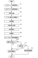
以下において、変速制御装置で演算する変速制御演算の一例を、図7に示すフローチャートに基づいて説明する。この変速制御演算は、ある所定の制御周期(例えば20ms毎)に実行される。
【0045】
ステップS1では、入力ディスク回転センサ84により入力ディスク回転数ωidを検出する。
【0046】
ステップS2では、出力ディスク回転センサ83により出力ディスク回転数ωodを検出する。
【0047】
ステップS3では、入力ディスク回転数ωidと出力ディスク回転数ωodとから、式(4)を用いて、変速比Gを演算する。
【0048】
ステップS4では、アクセル踏み込み量センサでアクセル踏み込み量APSを読み込む。
【0049】
ステップS5では、出力ディスク回転数ωidから、式(1)を用いて、車速VSPを演算する。
【0050】
ステップS6では、まず、アクセル踏み込み量APSと車速VSPとから、図5の変速マップを用いて、到達エンジン回転数ωteを求める。次に、到達エンジン回転数ωteと出力ディスク回転数ωodとから、式(2)を用いて到達CVT変速比Gtを算出する。そして、到達CVT変速比Gtから、式(3)に示すローパスフィルタを用いて目標変速比G*を算出する。
【0051】
ステップS7では、入力ディスク回転センサ84もしくは出力ディスク回転センサ83からの2層のパルス信号で、進行方向を判断する。
【0052】
ステップS8では、油温センサ89により油温を検出する。
【0053】
ステップS9では、図6に示す油温とステップモータ保証速度との関係を用いて、油温からステップモータ保証速度を算出する。
【0054】
ステップS10では、ステップモータ保証速度が、後進時、目標変速比と変速比との偏差が保証可能な速度より大きいかどうかを判断し、大きいときはステップS12へ進み、小さいときはステップS13へ進む。
【0055】
ステップS11では、ステップS7で判断した進行方向が前進ならばステップS12へ進み、後進ならばステップS13へ進む。
【0056】
ステップS12では、目標変速比G*と変速比Gとから、式(8)で表すPID制御器を用いて、ステップモータ変位の駆動指令値uを演算する。
【0057】
ステップS13では、式(16)で表される範囲内となるようにステップモータ変位の駆動指令値uを設定する。
【0058】
以上説明したように、後退時に、検出された油温に応じてステップモータの最大駆動速度を検出し、このステップモータの最大駆動速度が偏差の補償に必要な速度よりも小さいときは、変速比が減速側に変速すると共に、トラニオンオフセット方向のストッパに当たらない値とすることで、ステップモータ駆動速度が目標変速比と変速比との偏差を補償できない速度であっても、ハイ側変速による駆動力の減少を抑えることができ、かつ、トラニオンはオフセット方向のストッパに接触することがない。
【0059】
(実施の形態2)
次に、本発明の無段変速機の変速制御装置における実施の形態2について説明する。基本的な構成は実施の形態1と同様であるため、異なる部分についてのみ説明する。
【0060】
図8は実施の形態2における変速制御装置を備えたTCVT10の構成図である。実施の形態2では、運転者の操作するシフトレバーの位置を検出するシフト位置検出手段が設けられている点が異なる。
【0061】
次に、変速制御装置80において実行される変速制御の異なる点について説明する。前後進検出手段105では、車両の前後進を検出する。例えば、先ず、セレクトレバーのシフト位置から、シフト位置がDレンジならば前進、Rレンジならば後進と推定する。そして、目標変速比G*に対し変速比Gが、yn+ytsより増速側になった場合、前進と推定しているときは後進に切り換え、後進と推定しているときは前進に切り換える。ここで、ynは、変速比の増速側検出誤差最大値,ytsはトルクシフトによる目標変速比に対する変速比のずれの最大値である。このように切り換える理由を以下に述べる。
【0062】
シフト位置から前後進を判断しているとき、急な坂道などではシフト位置と進行方向とが異なる状況になる可能性がある。補償判断手段103では、ステップモータの速度が遅く、目標変速比G*と変速比Gとの偏差が補償できないと判断しているとき、前進を後進と誤判断すると、目標変速比G*に対して変速比Gが増速側に発散する。一方、後進を前進と誤判断すると、目標変速比G*に対して変速比が減速側もしくは増速側に発散する。後者の場合、減速側への発散は、後進と正しく判断している場合と結果的に同じとなるので許容する。しかしながら増速側への発散は、上述したように希望の加速感が得られない原因となる。そこで、この特性を利用して、目標変速比に対する増速側への変速比のずれをみて、進行方向の推定を切り換える。これにより、通常制御時に取りうる目標変速比に対する増速側への変速比のずれ量の最大値より増速側のときに切り換えるため、通常制御のときに対し大きく偏差が広がらないため、発進の違和感を抑制することができる。
【0063】
また、変速比の検出値はセンサのノイズの幅がずれる可能性があり、更にトルクシフトがある場合は、このトルクシフト幅分ずれる可能性がある。これらから、正常時偏差の最大値は、センサのノイズの幅とトルクシフトの幅との和(yn+yts)となる。この正常時偏差の最大値を用いることで、より確実に進行方向と制御が一致しているか否かを判断することができ、違和感のない発進を確保することができる。
【0064】
次に実施の形態2における変速制御装置で演算する変速制御演算の一例を、図7に示すフローチャートを用いて説明する。この変速制御演算は、ある所定の制御周期(例えば20ms毎)に実行される。
【0065】
ステップS1からS6及びステップS8からステップS13は実施の形態1と同様であるため、説明は省略する。
【0066】
ステップS7では、最初は、セレクトレバーのシフト位置から、シフト位置がDレンジであれば前進、Rレンジならば後進と推定する。そして、目標変速比G*に対し変速比Gが、yn+ytsより増速側になった場合、前進と推定している場合は後進へ推定を切り換え、後進と推定している場合は前進へ推定を切り換える。
【0067】
以上の操作により、ステップモータの駆動速度が、目標変速比と変速比との偏差を補償できない速度であっても、ハイ側変速による駆動力の減少を抑えることができ、かつトラニオンはオフセット方向のストッパに接触しない。
【0068】
(実施の形態3)
次に、本発明の無段変速機の変速制御装置における実施の形態3について説明する。基本的な構成は実施の形態1及び実施の形態2と同様であるため、異なる部分についてのみ説明する。
【0069】
次に、変速制御装置80において実行される変速制御の異なる点について説明する。前後進検出手段105では、車両の前後進を検出する。例えば、先ず、後進と推定し、その後、目標変速比G*に対し変速比Gが、yn+ytsより増速側になった場合、前進と推定しているときは後進に切り換え、後進と推定しているときは前進に切り換える。
【0070】
後進時に減速側に発散させるためには、式(16)を満たす位置にステップモータを駆動する必要がある。よって、より確実に減速側に発散させ、予め式(16)を満たす位置にステップモータを駆動しておくために、先ず、前後進の推定は後進としておく。そして、実施の形態2で示したように、後進を推定しているときに前進すると、目標変速比に対して変速比が増速側に発散するので、これを検出して進行方向の推定を前進に切り換える。同様に、前進と推定しているときに後進した場合も、目標変速比に対して変速比が減速側もしくは増速側に発散するので、実施の形態2と同じ理由で、減速側への発散は許容し、増速側への発散を見て、推定を後進に切り換える。
【0071】
これにより、後退したときに減速側に変速比が発散するように、予め変速アクチュエータを駆動するので、確実に後退時における変速比の増速側への発散が防止できると共に、前進を検知して、通常時制御に戻すことができる。これは、前記異常時制御手段104で演算する変速アクチュエータ駆動指令値で変速アクチュエータを駆動しているときに前進すると、変速比は増速側へ変速する特性による。
【0072】
次に実施の形態3における変速制御装置で演算する変速制御演算の一例を、図7に示すフローチャートを用いて説明する。この変速制御演算は、ある所定の制御周期(例えば20ms毎)に実行される。
【0073】
ステップS1からS6及びステップS8からステップS13は実施の形態1と同様であるため、説明は省略する。
【0074】
ステップS7では、最初は、後進と推定する。そして、目標変速比G*に対し変速比Gが、yn+ytsより増速側になった場合、前進と推定している場合は後進へ推定を切り換え、後進と推定している場合は前進へ推定を切り換える。
【0075】
以上の操作により、ステップモータの駆動速度が、目標変速比と変速比との偏差を補償できない速度であっても、ハイ側変速による駆動力の減少を抑えることができ、かつトラニオンはオフセット方向のストッパに接触しない。
【図面の簡単な説明】
【図1】 実施の形態1におけるトロイダル型無段変速機を表すスケルトン図である。
【図2】 実施の形態1におけるトロイダル型無段変速機の断面、および変速制御系の構成を表す概略図である。
【図3】 実施の形態1におけるトロイダル型無段変速機の変速制御装置を備えた制御系を含む構成図である。
【図4】 実施の形態1におけるトロイダル型無段変速機の変速制御装置の制御系を表すブロック図である。
【図5】 実施の形態1におけるアクセル開度毎の車速と到達エンジン回転数の関係を表すマップである。
【図6】 実施の形態1における油温に応じたステップモータ保証駆動速度を表すマップである。
【図7】 実施の形態1におけるトロイダル型無段変速機の変速制御装置の制御内容を表すフローチャートである。
【図8】 実施の形態2におけるトロイダル型無段変速機の変速制御装置を備えた制御系を含む構成図である。
【図9】 実施の形態3におけるトロイダル型無段変速機の変速制御装置を備えた制御系を含む構成図である。
【図10】 実施の形態におけるトラニオン軸方向ズレytsv算出マップである。
【図11】 実施の形態におけるトラニオン軸方向ズレytsb算出マップである。
【符号の説明】
10 トロイダル型無段変速機(TCVT)
12 トルクコンバータ
12a ポンプインペラ
12b タービンランナ
12c ステータ
12d ロックアップクラッチ
14 出力回転軸
16 トルク伝達軸
18,20 トロイダル変速部
22 ハウジング
23 トラニオン
24 傾転ストッパ
28 出力ギア
30 カウンターシャフト
30a 入力ギア
34 ローディングカム装置
36 スラストベアリング
40 前後進切換装置
42 遊星歯車機構
44 フォワードクラッチ
46 リバースブレーキ
50 油圧サーボ
51 サーボピストン
52 ステップモータ
53,54 リンク
55 プリセスカム
56 シフトコントロールバルブ
56S スプール
56D ドレーン
60 変速制御コントローラ
80 後進時制御装置
81 量センサ
82 パワーローラ回転数センサ
83 出力ディスク回転数センサ
84 入力ディスク回転数センサ
85 傾転角度センサ
86 トラニオン変位センサ
87 入力軸トルクセンサ
89 油温センサ[0001]
BACKGROUND OF THE INVENTION
The present invention relates to a speed change control device for a continuously variable transmission, and more particularly to speed ratio control during reverse travel.
[0002]
[Prior art]
Japanese Patent Laid-Open No. 8-93873 is known as a reverse control technology for a toroidal-type continuously variable transmission (hereinafter referred to as TCVT) having different shift control hydraulic systems for forward and reverse travel. Yes. This gazette is used when the shift control hydraulic system at the time of reverse drive fails or when the shift control hydraulic system at the forward side is used by mistake at the time of reverse drive. At this time, a drive command value calculated so that the gear ratio is shifted to the speed increase side is commanded to the gear shift actuator using the shift control at the time of forward movement. The TCVT shifts toward the deceleration side because the shift direction with respect to the trunnion offset differs between forward and reverse. Thereby, the start by the gear ratio on the deceleration side can be secured.
[0003]
Here, the reason for using different shift control hydraulic systems for forward and backward travel will be described. The characteristics of the tilt angle (transmission ratio) with respect to the trunnion offset are unstable. For this reason, the TCVT is equipped with a recess cam that is mechanically connected to a shift control valve that supplies oil to the hydraulic actuator in response to the shift actuator displacement, and the tilt angle and trunnion displacement are fed back to the shift control valve via the recess cam. The shift control hydraulic system mechanically stabilizes the tilt angle characteristic with respect to the shift actuator displacement. However, since the rotation direction of the input / output disk is different between forward and reverse, the tilt direction of the trunnion with respect to the vertical offset is also different. Correspondingly, a shift control hydraulic system having different polarities is provided for forward and reverse movements, and used by switching between forward and reverse.
[0004]
Further, as a conventional technique for stably driving a speed change actuator while preventing an increase in size of the speed change actuator, a technique described in Japanese Patent Application Laid-Open No. 8-17842 is known. In TCVT, a suitable target gear ratio adapted to the driving state is calculated, a gear shift command such as a motor is displaced by a gear shift command corresponding to this, and the gear shift control valve is operated to a stroke position corresponding to the target gear ratio. Configure as follows. By this operation, the speed change control valve creates a speed change control pressure corresponding to the target speed change ratio, and the TCVT is steplessly shifted toward the target speed change ratio in response to the speed change control pressure. However, the viscosity of hydraulic oil for continuously variable transmissions varies with temperature and becomes high at low temperatures. In addition, the clearance between the valve body of the transmission control valve, which is usually made of aluminum, and the spool of the transmission control valve, which is usually made of iron, becomes smaller at lower temperatures. For these reasons, when the hydraulic oil temperature is low, the viscous resistance when the shift control valve is stroked increases, and the required driving force of the shift actuator that strokes the shift control valve increases when the shift control valve is low. The required driving force of the speed change actuator that causes the stroke to be increased when the temperature is low. Here, even when the hydraulic oil temperature is the same (the viscosity resistance of the speed change control valve is the same), the motor drive speed is changed from the viewpoint that the required drive force of the speed change actuator becomes smaller if the speed change actuator drive speed is reduced. By controlling according to the machine oil temperature, the required driving force of the speed change actuator is prevented from increasing even at low temperatures, thereby preventing an increase in size of the speed change actuator.
[0005]
[Problems to be solved by the invention]
However, in JP-A-8-93873, when the drive command value is increased to the speed increasing side (the unit shifts to the speed reducing side during reverse travel), the trunnion offset increases accordingly. For this reason, if the drive command value is increased too much on the acceleration side, the trunnion may come into contact with a stopper in the offset direction (specifically, a piston cylinder of a servo piston that is an axial displacement actuator of the trunnion). One of the effects of this is that the contact portion (specifically, piston or cylinder) between the trunnion and the stopper may be worn due to the trunnion tilting while being pressed against the stopper with a strong force. Further, when a plurality of power rollers are provided, the offset stopper position is not constant due to variations in processing accuracy. Due to this variation, the offset amount of each trunnion is different and the tilting speed is different in the state where it is in contact with the stopper. As a result, during a transition period until the trunnion comes into contact with the stopper of the tilt angle, the tilt angles are not the same, and the slip between the disk and the power roller at each power roller contact point increases. This slip can cause wear and heat generation. The above wear and heat generation may reduce the durability of the toroidal conduction unit.
[0006]
Also, when the TCVT does not have a reverse shift control hydraulic system and the forward shift control hydraulic system is also used on the reverse side, the feedback control cannot compensate for the deviation between the target gear ratio and the gear ratio. The technique disclosed in JP-A-8-93873 can be applied. In this case, the same problem as described above may occur.
[0007]
The situation in which the deviation between the target gear ratio and the gear ratio cannot be compensated for by this feedback control is when the gear ratio cannot be detected due to an abnormality of the sensor for detecting the gear ratio at the time of reverse travel, or in Japanese Patent Laid-Open No. 8-178042. As described in the official gazette, this may occur when the speed of the speed change actuator is reduced according to the oil temperature. Thus, when the deviation cannot be compensated for by feedback control, the gear ratio is shifted to the deceleration side or the acceleration side. When shifting to the deceleration side, there are generally few problems because the target speed ratio during reverse travel is in the vicinity of the maximum speed reduction ratio and the driving force increases. On the other hand, when shifting to the speed increasing side, the driving force decreases, and there is a possibility that a desired acceleration feeling cannot be obtained at the start.
[0008]
The present invention has been made paying attention to the above-mentioned problems, and the object of the present invention is to provide a continuously variable transmission capable of stable shift control even during reverse travel while improving the durability of the continuously variable transmission. An object of the present invention is to provide a shift control device for a machine.
[0009]
In order to solve the above problems, in the present invention,A trunnion that supports the back of a power roller that transmits power by the shearing force of oil between coaxially arranged input and output disks is provided, and the trunnion is tilted by offsetting the trunnion in the direction of the tilting axis of the trunnion by a hydraulic actuator, Performs continuously variable speed by moving the contact point between the power roller and the input / output disk.A toroidal conduction unit;A forward / reverse switching device disposed between the toroidal transmission unit and the drive source, and correcting the difference in the tilt direction of the trunnion when the vehicle moves forward and when the vehicle moves backward with respect to the offset The oil is supplied to the hydraulic actuator so that the characteristics of the gear ratio with respect to the speed change actuator become stable at the time, and the speed change control hydraulic system is also used for forward and reverse travelA transmission control device for a continuously variable transmission comprising a transmission control hydraulic system;Target speed ratio setting means for setting the target speed ratio; speed ratio detection means for detecting or estimating the speed ratio;Forward / reverse detection means for detecting or estimating forward / backward movement of the vehicle, drive speed estimation means for estimating the maximum drive speed of the shift actuator, and electronically feeding back the detected gear ratio, the target gear ratio and the The normal time control means for calculating the drive command value of the shift actuator so as to compensate for the deviation according to the deviation from the gear ratio, and the compensation for the deviation between the target gear ratio and the gear ratio is the normal time control. A compensation judgment means for judging whether or not the compensation is possible, and when the compensation judgment means judges that the deviation cannot be compensated, the drive command value of the speed change actuator is shifted to the speed reduction side and the trunnion is changed. An abnormality control means for setting the displacement so that the displacement does not hit the stopper in the trunnion offset direction, and the compensation judgment means detects reverse travel and When the maximum drive speed of the actuator is below a predetermined value, it is determined that the deviation between the target gear ratio and the gear ratio cannot be compensated for, and the drive command value of the gear shift actuator calculated by the abnormal time control means is the gear ratio during reverse travel. The above-mentioned problem is solved by changing the speed toward the deceleration side and setting the trunnion to a value that does not hit the stopper in the trunnion offset direction.
[0010]
【The invention's effect】
In the present invention, even when the driving speed of the step motor cannot be guaranteed due to changes in the driving environment, it is possible to perform reverse starting with a low gear ratio, and to suppress wear and heat generation of the trunnion, power roller, and input / output disk. This makes it possible to improve the durability of the continuously variable transmission and achieve stable shift control.
[0011]
DETAILED DESCRIPTION OF THE INVENTION
(Embodiment 1)
[0012]
FIG. 1 shows a skeleton diagram of a toroidal-type continuously variable transmission 10 (hereinafter referred to as TCVT) in Embodiment 1 of the present invention, and FIG. 2 shows a cross section of
[0013]
An engine rotation (not shown) as a power source provided on the left side in FIG. 1 is input to the
[0014]
The first and second
[0015]
The first
[0016]
On the other hand, the first and
[0017]
A
[0018]
A
[0019]
The forward /
[0020]
In the forward /
[0021]
The
[0022]
FIG. 2 is a mechanical configuration diagram of a hydraulic system that performs shift control of the
[0023]
The
[0024]
The
[0025]
The
[0026]
During advance, the
[0027]
Here, the reaching point of the shift is determined by the displacement of the
[0028]
On the other hand, at the time of reverse travel, the tilt direction with respect to the vertical displacement of the power roller is different from that at the time of forward travel. As a result, the
[0029]
FIG. 3 is a configuration diagram of the
[0030]
The accelerator
[0031]
The speed
[0032]
FIG. 4 is a block diagram showing the shift control executed in the
(Formula 1)
![]()
[0033]
Next, reached engine speed ωteAnd output disk speed ωodFrom the above, the reached CVT gear ratio G using the relationship shown in equation (2)tIs calculated.
(Formula 2)
Finally, reaching CVT gear ratio GtFrom the target gear ratio G using, for example, a low-pass filter shown in Expression (3)*Is calculated.
(Formula 3)
[0035]
In the gear ratio detecting means 101, for example, the input disk rotational speed ωidDetection value and output disk rotation speed ωodThe transmission ratio detection value is calculated from the detected value using the relationship shown in equation (4).
(Formula 4)
In the normal control means 103, the target gear ratio G*And the gear ratio G are input, and a drive command value for the
(Formula 5)
(Formula 7)
[0037]
If the output of the TCVT system expressed by Equation (5) and Equation (6) is the tilt angle φ, this system is a controllable observable system. For this reason, the tilt angle (gear ratio) can be stabilized by feedback control of the state quantity. For example, the PID controller expressed by the following equation is used to stabilize the speed ratio characteristics with respect to the target speed ratio.
(Formula 8)
[0038]
The forward / reverse detection means 105 detects the forward / backward movement of the vehicle. For example, the forward / backward movement is directly detected from the detection result of the rotation direction by the two-phase pulse signal from the input
[0039]
The drive speed estimating means 106 estimates the guaranteed drive speed of the
[0040]
In the compensation determination means 103, the target gear ratio G*If the compensation is possible, the drive command value calculated by the normal control means 102 is output, and if it cannot be compensated, it is calculated by the abnormal time control means 104 described later. Command drive command value to step motor 52TheFor example, the guaranteed speed of the stepping
[0041]
When the abnormality control means 104 cannot compensate for the deviation between the target gear ratio and the gear ratio, the drive command for the
(Formula 9)
![]()
(Formula 11)
![]()
[0042]
Further, the steady value y of the trunnion displacement y from the equation (6)s(Y value when dy / dt = 0) is expressed by the following equation.
(Formula 12)
(Formula 13)
(Formula 14)
![]()
[0043]
Y shown in Formula (12)sHowever, if the area | region of the step motor displacement u is calculated | required so that y of Formula (14) may be satisfy | filled, the following Formula will be obtained.
(Formula 15)
From the above, the step motor drive command value region is expressed by the following equation.
(Formula 16)
(Formula 17)
Hereinafter, an example of the shift control calculation performed by the shift control device will be described based on the flowchart shown in FIG. This shift control calculation is executed at a predetermined control cycle (for example, every 20 ms).
[0045]
At step S1, the input
[0046]
In step S2, the output
[0047]
In step S3, the input disk rotational speed ωidAnd output disk speed ωodThus, the gear ratio G is calculated using the equation (4).
[0048]
In step S4, the accelerator depression amount APS is read by the accelerator depression amount sensor.
[0049]
In step S5, the output disk rotational speed ωidFrom this, the vehicle speed VSP is calculated using equation (1).
[0050]
In step S6, first, the reached engine speed ω is calculated from the accelerator depression amount APS and the vehicle speed VSP using the shift map of FIG.teAsk for. Next, reached engine speed ωteAnd output disk speed ωodTherefore, using formula (2), the ultimate CVT gear ratio GtIs calculated. And reaching CVT gear ratio GtFrom the target gear ratio G using the low-pass filter shown in equation (3)*Is calculated.
[0051]
In step S7, the traveling direction is determined based on the two-layer pulse signal from the input
[0052]
In step S8, the oil temperature is detected by the
[0053]
In step S9, the step motor guaranteed speed is calculated from the oil temperature using the relationship between the oil temperature and the step motor guaranteed speed shown in FIG.
[0054]
In step S10, it is determined whether or not the step motor guaranteed speed is larger than the speed at which the deviation between the target gear ratio and the gear ratio can be guaranteed during reverse travel. If larger, the process proceeds to step S12, and if smaller, the process proceeds to step S13. .
[0055]
In step S11, if the traveling direction determined in step S7 is forward, the process proceeds to step S12, and if reverse, the process proceeds to step S13.
[0056]
In step S12, the target gear ratio G*And the gear ratio G, the drive command value u for the step motor displacement is calculated using the PID controller represented by the equation (8).
[0057]
In step S13, the drive command value u for the step motor displacement is set so as to be within the range represented by equation (16).
[0058]
As explained above, the maximum drive speed of the step motor is detected according to the detected oil temperature during reverse, and when the maximum drive speed of the step motor is smaller than the speed required for compensation for deviation, the gear ratio The gear shifts to the deceleration side and does not hit the stopper in the trunnion offset direction, so that even if the step motor drive speed cannot compensate for the deviation between the target gear ratio and the gear ratio, the high-side gear is driven. The decrease in force can be suppressed, and the trunnion does not contact the stopper in the offset direction.
[0059]
(Embodiment 2)
Next, a second embodiment of the transmission control device for a continuously variable transmission according to the present invention will be described. Since the basic configuration is the same as that of the first embodiment, only different parts will be described.
[0060]
FIG. 8 is a configuration diagram of the
[0061]
Next, different points of the shift control executed in the
[0062]
When the forward / backward movement is determined from the shift position, the shift position and the traveling direction may be different on a steep slope. In the compensation determination means 103, the speed of the step motor is slow and the target gear ratio G*If it is determined that the deviation between the gear ratio and the gear ratio G cannot be compensated, and the forward gear is erroneously determined to be reverse, the target gear ratio G*On the other hand, the gear ratio G diverges toward the speed increasing side. On the other hand, if the reverse is mistakenly determined to be forward, the target gear ratio G*On the other hand, the gear ratio diverges to the deceleration side or the acceleration side. In the latter case, the divergence to the deceleration side is allowed because it is the same as the case where it is correctly determined that the vehicle is moving backward. However, the divergence toward the speed increasing side causes the desired acceleration feeling not to be obtained as described above. Therefore, using this characteristic, the estimation of the traveling direction is switched by looking at the shift of the speed ratio toward the speed increasing side with respect to the target speed ratio. As a result, since the switching is performed when the speed is higher than the maximum value of the shift ratio of the speed ratio to the speed increasing side with respect to the target speed ratio that can be obtained during the normal control, the deviation does not widen greatly compared with that during the normal control. Can suppress the sense of incongruityThe
[0063]
Further, the detection value of the transmission ratio may be shifted in the noise width of the sensor, and if there is a torque shift, there is a possibility that it is shifted by this torque shift width. From these, the maximum value of the normal deviation is the sum of the sensor noise width and the torque shift width (yn+ Yts) By using the maximum value of the deviation at normal time, it is possible to more reliably determine whether or not the direction of travel matches the control, and it is possible to ensure a start without a sense of incongruity.The
[0064]
Next, an example of the shift control calculation performed by the shift control apparatus according to Embodiment 2 will be described with reference to the flowchart shown in FIG. This shift control calculation is executed at a predetermined control cycle (for example, every 20 ms).
[0065]
Steps S1 to S6 and steps S8 to S13 are the same as those in the first embodiment, and a description thereof will be omitted.
[0066]
In step S7, it is initially estimated from the shift position of the select lever that the vehicle moves forward if the shift position is in the D range, and reverse if it is in the R range. And the target gear ratio G*The gear ratio G is yn+ YtsWhen the speed is further increased, the estimation is switched to the reverse if it is estimated to be forward, and the estimation is switched to the forward if it is estimated to be backward.
[0067]
With the above operation, even if the driving speed of the step motor is a speed at which the deviation between the target speed ratio and the speed ratio cannot be compensated for, the reduction of the driving force due to the high side speed change can be suppressed, and the trunnion is in the offset direction. Do not touch the stopper.
[0068]
(Embodiment 3)
Next, a third embodiment of the transmission control device for a continuously variable transmission according to the present invention will be described. Since the basic configuration is the same as that of the first and second embodiments, only different parts will be described.
[0069]
Next, different points of the shift control executed in the
[0070]
In order to diverge to the deceleration side during reverse travel, it is necessary to drive the step motor to a position that satisfies the equation (16). Therefore, in order to diverge more reliably on the deceleration side and drive the step motor to a position satisfying the equation (16) in advance, the forward / backward estimation is first set to reverse. Then, as shown in the second embodiment, if the vehicle travels forward while estimating reverse, the gear ratio diverges toward the speed increase side with respect to the target gear ratio, and this is detected to estimate the traveling direction. Switch to forward. Similarly, when the vehicle travels backward when estimating forward, the gear ratio diverges toward the deceleration side or the acceleration side with respect to the target gear ratio, and therefore divergence toward the deceleration side for the same reason as in the second embodiment. Allow, and see the divergence to the speed increasing side, and switch the estimation to reverse.
[0071]
As a result, since the speed change actuator is driven in advance so that the speed ratio diverges on the deceleration side when reversing, it is possible to reliably prevent the speed ratio from diverging to the speed increasing side and to detect forward movement. Can return to normal control. This is due to the characteristic that when the shift actuator is driven with the shift actuator drive command value calculated by the abnormal time control means 104, the gear ratio shifts to the acceleration side when the shift actuator is driven forward.The
[0072]
Next, an example of the shift control calculation performed by the shift control apparatus in Embodiment 3 will be described with reference to the flowchart shown in FIG. This shift control calculation is executed at a predetermined control cycle (for example, every 20 ms).
[0073]
Steps S1 to S6 and steps S8 to S13 are the same as those in the first embodiment, and a description thereof will be omitted.
[0074]
In step S7, it is initially estimated that the vehicle travels backward. And the target gear ratio G*The gear ratio G is yn+ YtsWhen the speed is further increased, the estimation is switched to the reverse if it is estimated to be forward, and the estimation is switched to the forward if it is estimated to be backward.
[0075]
With the above operation, even if the driving speed of the step motor is a speed at which the deviation between the target speed ratio and the speed ratio cannot be compensated for, the reduction of the driving force due to the high side speed change can be suppressed, and the trunnion is in the offset direction. Do not touch the stopper.
[Brief description of the drawings]
FIG. 1 is a skeleton diagram showing a toroidal continuously variable transmission according to a first embodiment.
FIG. 2 is a schematic diagram showing a cross section of a toroidal-type continuously variable transmission and a configuration of a transmission control system in the first embodiment.
3 is a configuration diagram including a control system including a shift control device for a toroidal-type continuously variable transmission according to Embodiment 1. FIG.
4 is a block diagram showing a control system of a shift control device for a toroidal-type continuously variable transmission according to Embodiment 1. FIG.
FIG. 5 is a map showing the relationship between the vehicle speed and the reached engine speed for each accelerator opening in the first embodiment.
FIG. 6 is a map showing a stepping motor guaranteed driving speed according to the oil temperature in the first embodiment.
FIG. 7 is a flowchart showing the control contents of the shift control device for the toroidal-type continuously variable transmission according to the first embodiment.
FIG. 8 is a configuration diagram including a control system including a shift control device for a toroidal-type continuously variable transmission according to a second embodiment.
FIG. 9 is a configuration diagram including a control system including a shift control device for a toroidal-type continuously variable transmission according to a third embodiment.
FIG. 10 shows trunnion axial deviation y in the embodiment.tsvIt is a calculation map.
FIG. 11 is a trunnion axial deviation y in the embodiment.tsbIt is a calculation map.
[Explanation of symbols]
10 Toroidal continuously variable transmission (TCVT)
12 Torque converter
12a Pump impeller
12b Turbine runner
12c stator
12d lock-up clutch
14 Output rotation axis
16 Torque transmission shaft
18, 20 Toroidal transmission
22 Housing
23 Trunnion
24 Tilt stopper
28 Output gear
30 Countershaft
30a Input gear
34 Loading cam device
36 Thrust bearing
40 Forward / reverse switching device
42 Planetary gear mechanism
44 Forward clutch
46 Reverse brake
50 Hydraulic servo
51 Servo piston
52 step motor
53, 54 links
55 Precess Cam
56 Shift control valve
56S spool
56D drain
60 Shift control controller
80 Reverse control device
81 Quantity sensor
82 Power roller rotational speed sensor
83 Output disk speed sensor
84 Input disk speed sensor
85 Tilt angle sensor
86 Trunnion displacement sensor
87 Input shaft torque sensor
89 Oil temperature sensor
Claims (5)
前記トロイダル伝導ユニットと駆動源との間に配置された前後進切換装置と、
前記オフセットに対して車両の前進時と車両の後進時とにおける前記トラニオンの傾転方向の違いを補正して、前進時において変速アクチュエータに対する変速比の特性が安定となるように、前記油圧アクチュエータへ油を供給し、前進時と後進時とで変速制御油圧系を兼用した変速制御油圧系と、
を備えた無段変速機の変速制御装置において、
目標変速比を設定する目標変速比設定手段と、
変速比を検出または推定する変速比検出手段と、
車両の前後進を検出または推定する前後進検出手段と、
前記変速アクチュエータの最大駆動速度を推定する駆動速度推定手段と、
検出された変速比を電子的にフィードバックして、前記目標変速比と前記変速比との偏差に応じて、該偏差を補償するように変速アクチュエータの駆動指令値を演算する通常時制御手段と、
前記目標変速比と前記変速比との偏差の補償が、前記通常時制御手段により補償可能かどうかを判断する補償判断手段と、
該補償判断手段により前記偏差の補償ができないと判断したときは、変速アクチュエータの駆動指令値を、変速比が減速側に変速すると共に、トラニオン変位がトラニオンオフセット方向のストッパに当たらない値とする異常時制御手段と、
を設け、
前記補償判断手段は、後進が検出され、かつ、変速アクチュエータの最大駆動速度が所定値以下の時は、目標変速比と変速比との偏差が補償できないと判断し、前記異常時制御手段で演算する変速アクチュエータの駆動指令値は、後進時に、変速比が減速側に変速すると共に、トラニオンがトラニオンオフセット方向のストッパに当たらない値とすることを特徴とする無段変速機の変速制御装置。A trunnion that supports the back of a power roller that transmits power by the shearing force of oil between the coaxially arranged input and output disks is provided. A toroidal transmission unit that performs continuously variable speed by moving the contact point between the power roller and the input / output disk;
A forward / reverse switching device disposed between the toroidal transmission unit and a drive source;
To the hydraulic actuator, the difference in the tilt direction of the trunnion between when the vehicle moves forward and when the vehicle moves backward is corrected with respect to the offset, so that the characteristics of the gear ratio with respect to the speed change actuator become stable at the time of forward movement. A shift control hydraulic system that supplies oil and also serves as a shift control hydraulic system during forward and reverse travel ,
In a continuously variable transmission shift control device comprising:
Target gear ratio setting means for setting the target gear ratio;
Gear ratio detecting means for detecting or estimating the gear ratio;
Forward / reverse detection means for detecting or estimating forward / backward movement of the vehicle;
Drive speed estimating means for estimating the maximum drive speed of the variable speed actuator;
A normal time control means for electronically feeding back the detected gear ratio and calculating a drive command value of the gear shift actuator so as to compensate for the deviation according to the deviation between the target gear ratio and the gear ratio;
Compensation determining means for determining whether or not the compensation of the deviation between the target speed ratio and the speed ratio can be compensated by the normal time control means;
When it is determined by the compensation determining means that the deviation cannot be compensated, the drive command value of the speed change actuator is changed to a value at which the gear ratio shifts to the deceleration side and the trunnion displacement does not hit the stopper in the trunnion offset direction. Time control means;
Provided,
The compensation determination means determines that the deviation between the target speed ratio and the speed ratio cannot be compensated when reverse travel is detected and the maximum drive speed of the speed change actuator is equal to or less than a predetermined value, and is calculated by the abnormal time control means. A transmission control device for a continuously variable transmission, wherein the drive command value of the speed change actuator is a value at which the speed ratio shifts to the deceleration side and the trunnion does not hit the stopper in the trunnion offset direction during reverse travel.
運転者の操作するシフトトレバーのシフト位置を検出するシフト位置検出手段を設けて、先ず前記シフト位置から前進か後進かを推定し、
該推定後、前記前後進検出手段は、変速比が、通常制御時に取りうる目標変速比に対する増速比側への変速比のずれ量(以下、正常時偏差と記載する)の最大値よりも増速側となった場合に、車両が前進していると推定しているときは後進と判断を切り換え、車両が後進していると推定しているときは前進と判断を切り換えることを特徴とする無段変速機の変速制御装置。The transmission control device for a continuously variable transmission mechanism according to claim 1,
Provided with a shift position detecting means for detecting the shift position of the shift lever operated by the driver, first estimating from the shift position whether it is forward or reverse,
After the estimated, the forward-reverse detecting means, speed change ratio, than the maximum value of the deviation amount of the gear ratio of the speed increasing ratio side with respect to the target speed ratio that can be taken at the time of normal control (hereinafter referred to as normal time deviation) If the became the acceleration side, characterized in that switching the decision and forward when estimates that switching decision and the reverse, the vehicle is moving in reverse when estimates that the vehicle is moving forward A transmission control device for a continuously variable transmission.
前記前後進検出手段は、先ず車両が後進していると推定し、該推定後に、変速比が、通常制御時に取りうる目標変速比に対する増速比側への正常時偏差の最大値よりも増速側となった場合に、車両が前進していると推定しているときは後進と判断を切り換え、車両が後進していると推定しているときは前進と判断を切り換えることを特徴とする無段変速機の変速制御装置。The transmission control device for a continuously variable transmission according to claim 2,
The forward / reverse detection means first estimates that the vehicle is moving backward, and after the estimation, the gear ratio increases from the maximum normal deviation to the speed increase ratio with respect to the target speed ratio that can be taken during normal control. when a fast side, when estimates that the vehicle is moving forward switching decision and the reverse, when the vehicle is estimated to be backward is characterized by switching the determination and forward A transmission control device for a continuously variable transmission.
前記正常時偏差の最大値を、前記トロイダル伝導ユニットに入力軸トルクが作用することによる変速比のずれ(以下、トルクシフトと記載する)と、変速比検出誤差の最大値と に応じて、設定することを特徴とする無段変速機の変速制御装置。The transmission control device for a continuously variable transmission according to any one of claims 2 and 3 ,
The maximum value of the normal time deviation, the deviation of the gear ratio due to the action of the input shaft torque to the toroidal conducting unit (hereinafter referred to as torque shift) and, depending on the maximum value of the speed ratio detection error, set A transmission control device for a continuously variable transmission.
前記トロイダル伝導ユニットの油温を検出又は推定する油温検出手段を設け、
前記駆動速度推定手段は、油温に応じて前記変速アクチュエータの最大駆動速度を推定することを特徴とする無段変速機の変速制御装置。The transmission control device for a continuously variable transmission according to any one of claims 1 to 4 ,
An oil temperature detecting means for detecting or estimating the oil temperature of the toroidal conduction unit is provided,
The shift control device for a continuously variable transmission, wherein the drive speed estimation means estimates a maximum drive speed of the shift actuator according to an oil temperature.
Priority Applications (2)
| Application Number | Priority Date | Filing Date | Title |
|---|---|---|---|
| JP2002245210A JP3960165B2 (en) | 2002-08-26 | 2002-08-26 | Shift control device for continuously variable transmission |
| US10/436,162 US6931316B2 (en) | 2002-06-05 | 2003-05-13 | Toroidal continuously variable transmission control apparatus |
Applications Claiming Priority (1)
| Application Number | Priority Date | Filing Date | Title |
|---|---|---|---|
| JP2002245210A JP3960165B2 (en) | 2002-08-26 | 2002-08-26 | Shift control device for continuously variable transmission |
Publications (2)
| Publication Number | Publication Date |
|---|---|
| JP2004084759A JP2004084759A (en) | 2004-03-18 |
| JP3960165B2 true JP3960165B2 (en) | 2007-08-15 |
Family
ID=32053470
Family Applications (1)
| Application Number | Title | Priority Date | Filing Date |
|---|---|---|---|
| JP2002245210A Expired - Fee Related JP3960165B2 (en) | 2002-06-05 | 2002-08-26 | Shift control device for continuously variable transmission |
Country Status (1)
| Country | Link |
|---|---|
| JP (1) | JP3960165B2 (en) |
Families Citing this family (2)
| Publication number | Priority date | Publication date | Assignee | Title |
|---|---|---|---|---|
| JP5071239B2 (en) * | 2008-05-16 | 2012-11-14 | トヨタ自動車株式会社 | Toroidal-type continuously variable transmission and synchronization method of its power roller |
| JP6907960B2 (en) * | 2018-01-29 | 2021-07-21 | トヨタ自動車株式会社 | Control device for vehicle power transmission device |
-
2002
- 2002-08-26 JP JP2002245210A patent/JP3960165B2/en not_active Expired - Fee Related
Also Published As
| Publication number | Publication date |
|---|---|
| JP2004084759A (en) | 2004-03-18 |
Similar Documents
| Publication | Publication Date | Title |
|---|---|---|
| US6931316B2 (en) | Toroidal continuously variable transmission control apparatus | |
| US6909953B2 (en) | Shift control of continuously-variable transmission | |
| US6312357B1 (en) | Speed ratio controller and control method of non-finite speed ratio transmission device | |
| US6317672B1 (en) | Controller for infinite speed ratio transmission | |
| JP3960165B2 (en) | Shift control device for continuously variable transmission | |
| JP4007078B2 (en) | Shift control device for continuously variable transmission | |
| JP3572609B2 (en) | Transmission control device for continuously variable transmission | |
| JP2004011728A (en) | Speed change control device for continuously variable transmission | |
| JP4284968B2 (en) | Shift control device for continuously variable transmission | |
| JP4304745B2 (en) | Powertrain control device | |
| JP3870676B2 (en) | Shift control device for continuously variable transmission | |
| JP4013690B2 (en) | Shift control device for continuously variable transmission | |
| JP4253891B2 (en) | Powertrain control device | |
| JP4285195B2 (en) | Continuously variable transmission | |
| JP2000179674A (en) | Control device of power train | |
| JP6384249B2 (en) | Toroidal continuously variable transmission | |
| JP4379065B2 (en) | Continuously variable transmission | |
| JP2000179669A (en) | Control device of power train | |
| JP2000046167A (en) | Transmission control device for continuously variable transmission | |
| JP4003880B2 (en) | Shift control device for toroidal type continuously variable transmission | |
| JP3427700B2 (en) | Transmission control device for continuously variable transmission | |
| JP3736471B2 (en) | Toroidal continuously variable transmission | |
| JPH11247984A (en) | Transmission control device for indefinite gear ratio type continuously variable transmission | |
| JP2004068936A (en) | Transmission ratio control device for continuously variable transmission mechanism | |
| JPH09210164A (en) | Troidal continuously variable transmission |
Legal Events
| Date | Code | Title | Description |
|---|---|---|---|
| A621 | Written request for application examination |
Free format text: JAPANESE INTERMEDIATE CODE: A621 Effective date: 20050526 |
|
| RD04 | Notification of resignation of power of attorney |
Free format text: JAPANESE INTERMEDIATE CODE: A7424 Effective date: 20051116 |
|
| A131 | Notification of reasons for refusal |
Free format text: JAPANESE INTERMEDIATE CODE: A131 Effective date: 20070123 |
|
| A977 | Report on retrieval |
Free format text: JAPANESE INTERMEDIATE CODE: A971007 Effective date: 20070126 |
|
| A521 | Written amendment |
Free format text: JAPANESE INTERMEDIATE CODE: A523 Effective date: 20070320 |
|
| TRDD | Decision of grant or rejection written | ||
| A01 | Written decision to grant a patent or to grant a registration (utility model) |
Free format text: JAPANESE INTERMEDIATE CODE: A01 Effective date: 20070424 |
|
| A61 | First payment of annual fees (during grant procedure) |
Free format text: JAPANESE INTERMEDIATE CODE: A61 Effective date: 20070507 |
|
| R150 | Certificate of patent or registration of utility model |
Free format text: JAPANESE INTERMEDIATE CODE: R150 |
|
| FPAY | Renewal fee payment (event date is renewal date of database) |
Free format text: PAYMENT UNTIL: 20100525 Year of fee payment: 3 |
|
| FPAY | Renewal fee payment (event date is renewal date of database) |
Free format text: PAYMENT UNTIL: 20110525 Year of fee payment: 4 |
|
| FPAY | Renewal fee payment (event date is renewal date of database) |
Free format text: PAYMENT UNTIL: 20130525 Year of fee payment: 6 |
|
| FPAY | Renewal fee payment (event date is renewal date of database) |
Free format text: PAYMENT UNTIL: 20140525 Year of fee payment: 7 |
|
| LAPS | Cancellation because of no payment of annual fees |