JP3958692B2 - System and method for determining the logic state of a memory cell in a magnetic tunnel junction memory device - Google Patents
System and method for determining the logic state of a memory cell in a magnetic tunnel junction memory device Download PDFInfo
- Publication number
- JP3958692B2 JP3958692B2 JP2003013288A JP2003013288A JP3958692B2 JP 3958692 B2 JP3958692 B2 JP 3958692B2 JP 2003013288 A JP2003013288 A JP 2003013288A JP 2003013288 A JP2003013288 A JP 2003013288A JP 3958692 B2 JP3958692 B2 JP 3958692B2
- Authority
- JP
- Japan
- Prior art keywords
- memory cell
- memory
- bias voltage
- mtj
- bias
- Prior art date
- Legal status (The legal status is an assumption and is not a legal conclusion. Google has not performed a legal analysis and makes no representation as to the accuracy of the status listed.)
- Expired - Fee Related
Links
Images


Classifications
-
- G—PHYSICS
- G11—INFORMATION STORAGE
- G11C—STATIC STORES
- G11C11/00—Digital stores characterised by the use of particular electric or magnetic storage elements; Storage elements therefor
- G11C11/02—Digital stores characterised by the use of particular electric or magnetic storage elements; Storage elements therefor using magnetic elements
- G11C11/14—Digital stores characterised by the use of particular electric or magnetic storage elements; Storage elements therefor using magnetic elements using thin-film elements
- G11C11/15—Digital stores characterised by the use of particular electric or magnetic storage elements; Storage elements therefor using magnetic elements using thin-film elements using multiple magnetic layers
Description
【0001】
【発明の属する技術分野】
本発明は、一般に、磁気トンネル接合(MTJ)メモリデバイスに関し、とりわけ、MTJメモリデバイスにおけるメモリセルの論理状態を判定するためのシステム及び方法に関する。
【0002】
【従来の技術】
典型的な磁気トンネル接合(MTJ)メモリデバイスには、メモリセルのアレイが含まれる。各セルは、一般に、誘電体層によって分離された、2つの磁気薄膜層から構成される。薄膜層の一方の磁化は、変更可能であり、他方の薄膜層の磁化は、特定の方向に固定または「ピン留め(pinned)」される。磁化の変更が可能な磁気薄膜層は、一般に、「データ記憶層」と呼ばれ、ピン留めされた磁気薄膜層は、「基準層」と呼ばれる。
【0003】
導電性トレースは、一般に、メモリセルのアレイを横切るように経路指定される。これらの導電性トレースは、一般に、行及び列をなすように構成される。メモリセルの行に沿って延びる導電性トレースは、一般に、「ワード線」と呼ばれ、メモリセルの列に沿って延びる導電性トレースは、一般に、「ビット線」と呼ばれる。ワード線とビット線は、一般に、互いに対して垂直に配向される。ワード線とビット線の各交差点に配置された各メモリセルは、情報のビットを磁化の向きとして格納する。
【0004】
概して、データ記憶層における磁化の向きは、一般に、その「磁化容易軸」と呼ばれる、データ記憶層の軸に沿って整列する。一般に、外部磁界を加えることにより、所望の論理状態に従って、その磁化容易軸に沿ったデータ記憶層における磁化の向きが、基準層の磁化の向きに対して平行または反平行の向きに反転する。
【0005】
各メモリセルの磁化の向きは、任意の時点において、2つの安定した向きの一方になる。これら2つの安定した向き、すなわち、平行と反平行は、それぞれ、論理値の「1」及び「0」を表している。選択されたメモリセルの磁化の向きは、選択されたメモリセルの位置で交差するワード線及びビット線に電流を供給することによって変更され得る。電流によって生じる磁界は、組み合わせられると、選択されたメモリセルの磁化の向きを平行から反平行に、またはその逆にスイッチすることができる。
【0006】
選択された磁気メモリセルは、通常、選択された磁気メモリセルで交差する特定のワード線とビット線に電流を加えることによって書き込まれる。一般に、特定のビット線に電流を加えることにより、選択された磁気メモリセルの磁化容易軸に沿ってほぼ一直線になる磁界が発生する。磁化容易軸に一直線になる磁界は、一般に、「長手方向書き込み磁界」と呼ばれる。特定のワード線に電流を加えることにより、一般に、選択された磁気メモリセルの磁化容易軸に対してほぼ垂直な磁界が発生する。
【0007】
一般に選択された1つの磁気メモリセルだけが、長手方向と垂直方向の両方の書き込み磁界を同時に受ける。選択されたメモリセルと同じワード線に結合された非選択のメモリセルは、一般に、垂直方向の書き込み磁界だけしか受けない。選択されたメモリセルと同じビット線に結合された非選択のメモリセルは、一般に、長手方向の書き込み磁界だけしか受けない。
【0008】
ワード線とビット線は、組み合わせられると、選択されたメモリセルの磁化の向きをスイッチする(すなわち、メモリセルに書き込む)働きをするので、一般に、ワード線とビット線は、総称して「書き込み線」と呼ばれる。書き込み線は、メモリセルに格納された論理値を読み取るためにも使用され得る。
【0009】
図1は、典型的なMTJメモリデバイスである簡略化された磁気ランダムアクセスメモリ(MRAM)アレイを例示した平面図である。アレイ100には、メモリセル120、ワード線130、及びビット線132が含まれる。ワード線130及びビット線132は、総称して「書き込み線」と呼ばれる。メモリセル120は、ワード線130とビット線132の各交差点に配置される。一般に、ワード線130及びビット線132は、互いに直交するように構成されており、メモリセル120は、ビット線132とワード線130との間に配置される。
【0010】
図2A、図2B、及び図2Cには、全体として、図1のMRAMアレイの単一メモリセル120におけるデータビットの格納が例示されている。図2Aに例示されたように、メモリセル120には、誘電体領域126によって分離された、活性磁気データ薄膜122とピン留め磁気薄膜124が含まれる。活性磁気データ薄膜122の磁化の向きは、固定されておらず、矢印M1によって示すように、2つの安定した向きをとることができる。対照的に、ピン留め磁気薄膜124は、矢印M2によって示すように、磁化の向きが固定されている。活性磁気データ薄膜122は、メモリセル120に対する書込み操作中に書き込み線(すなわち、図1のワード線130及びビット線132)に加えられる電流に応答して、その磁化の向きを回転させる。メモリセル120に格納されたデータビットの第1の論理状態は、図2Bに例示のように、M1及びM2が互いに平行である場合に示される。M1及びM2が平行である場合、メモリセル120に論理「1」状態が格納される。逆に、M1及びM2が、図2Cに例示のように、互いに反平行である場合には、第2の論理状態が示される。M1及びM2が反平行である場合、メモリセル120に論理「0」状態が格納される。図2B及び図2Cの場合、誘電体領域126が省略されている。図2A、図2B、及び図2Cは、全体として、ピン留め磁気薄膜124の上方に配置された活性磁気データ薄膜122を例示しているが、代案としてピン留め磁気薄膜124を活性磁気データ薄膜122の上方に配置することも可能である。
【0011】
メモリセル120の抵抗は、M1及びM2の向きによって異なる。M1及びM2が反平行(すなわち、論理「0」状態)である場合、メモリセル120の抵抗は最大になる。一方、M1及びM2の向きが平行(すなわち、論理「1」状態)の場合、メモリセル120の抵抗は最小になる。従って、メモリセル120に格納されたデータビットの論理状態は、メモリセル120を流れる電流を測定することによって判定され得る。
【0012】
図3は、アレイ100のセルの1つを流れるセンス電流を測定するためのセンシング回路150を備えたMTJアレイ100の略図である。アレイ100は、複数のワード線130と、複数のビット線132とから構成される。図1に関して既述のように、メモリセル120は、ワード線130とビット線132の各交差点に形成されている(単純化のため、最上部の行のメモリセルだけにしか番号が付いていないが、もちろん、メモリセルは、ワード線130とビット線132の各交差点に形成されている)。センス電流を測定することになる特定のセルが、メモリセル120aとして示されている。MTJアレイ100のビット線132のそれぞれに、バイアス電圧(Va)が印加される。同じバイアス電圧(Va)が、分りやすくするためワード線130aと表示された、メモリセル120aと交差するワード線を除いた、MTJアレイ100のワード線130のそれぞれにも印加される。Nのワード線130とNのビット線132を備えた対称アレイの場合、バイアス電圧Vaは、Nのビット線132の全てと、N−1のワード線130に印加されることになる。メモリセル120aと交差するワード線130aには、第2のバイアス電圧(Vb)が印加される。一般に、Va>Vbで、典型的な実施例の場合、Vbは接地電位である。従って、メモリセル120aを除いた、アレイ100の各メモリセル120のバイアス電圧は、0(Va−Va)になる。メモリセル120aのバイアス電圧は、(Va−Vb)であり、結果として、メモリセル120aにセンス電流(Isc)が流れる。センシング回路150が、接続151及び152によって、メモリセル120aに結合されている。センシング回路150は、バイアス電圧(Va−Vb)が印加される結果として、メモリセル120aに流れるセンス電流(Isc)を測定する。印加されるバイアス電圧(Va−Vb)におけるメモリセル120aの抵抗(R)は、印加されるバイアス電圧(Va−Vb)をセンス電流(Isc)で割ることによって計算される。
【0013】
図3のメモリセル120aのようなMTJアレイにおけるセルの論理状態は、一般に、印加されるバイアス電圧におけるメモリセルの抵抗と、論理「1」状態及び論理「0」状態に対応する所定の抵抗値とを比較することによって判定されてきた。しかしながら、MTJメモリデバイスは、量子力学的トンネル効果の原理に基づいて動作するので、特定のメモリセルにおけるセンス電流の大きさ、従って、セルの抵抗は、誘電体層の厚さに極めて大きく左右される。MTJデバイスのアレイ内における誘電体の厚さの変動は、現在の薄膜プロセス技術によって完全に除去されることができないので、これらの変動によって、アレイ内の異なるメモリセル内で測定されるセンス電流の大きさに一見したところ不均衡な変動が生じる可能性がある。このことは、アレイ内における異なるメモリセルの論理状態の判定が曖昧になる可能性がある。この曖昧さが実際に意味するところは、メモリセルの抵抗とある所定のしきい値を比較することによって、メモリセルのどれか1つのデータ状態を判定する場合、MTJメモリデバイスアレイを動作させると、データ検索のプロセス中に、多数のエラーを生じる潜在的可能性があるということである。これが生じるのは、同じ論理状態が格納されているメモリセル間における抵抗差が、その論理状態が「1」から「0」にスイッチされる際の1つのメモリセルにおける抵抗差を容易に超える可能性があるためである。
【0014】
この曖昧さを克服するための方法の1つは、破壊読出しとして知られるデータ検索プロセスを用いることである。破壊読出しには、一般に、(1)最初に、印加電圧に応答して、メモリセル内のセンス電流の大きさを測定するステップと、(2)ある既知の(あらかじめ決められた)状態(すなわち、「1」または「0」)をメモリセルに書き込むステップと、(3)次に、ステップ1において既に印加されているのと同じ印加電圧の第2の印加に応答して、メモリセルにおけるセンス電流の大きさを測定するステップと、(4)最初の測定と2度目の測定との間におけるセンス電流の大きさの差に基づいて、当該ビットの論理状態が本来は「1」であったか、「0」であったかを判定するステップとが必要とされる。さらに、ステップ4で判定されるメモリセルの本来の状態が、ステップ2においてセルに書き込まれる状態と異なる場合、さらなる書込み操作によって、メモリセルをその本来の状態に戻さなければならない。例えば、ステップ2において、メモリセルに「1」が書き込まれ、ステップ4において、そのメモリセルが本来「0」であったという判定が示されると、破壊読出しの完了後に、メモリセルへの書き込みによって、その本来の「0」状態に戻されなければならない。一方、ステップ2において、メモリセルに「1」が書き込まれ、ステップ4において、そのメモリセルが本来「1」であったという判定が示されると、再書き込み操作によって、メモリセルをその本来の状態に戻す必要がなくなる。
【0015】
破壊読出しプロセスを利用して、メモリセルの状態を判定することができるが、このプロセスにはいくつかの重大な欠点がある。破壊読出しプロセスには、メモリセルに既知の値を書き込み、さらに、場合によっては、その本来の値に書き戻すことが必要になることもあるので、破壊読出しプロセスでは、読み取りアクセス時間が著しく増大する。さらに、追加の書込み操作によって、電力消費が増大し、メモリセルの平均寿命が短くなる可能性がある。
【0016】
また、破壊読出しプロセスは、半選択スイッチングとして知られる望ましくない状態をもたらす傾向がある。半選択スイッチングは、N×Mのメモリセルを有するMTJメモリアレイ内において(ここで、N及びMは2以上である)、あるメモリセルを対象とした書込み操作によって、アレイ内の別のセルに望ましくない偶発的な状態変化が生じる場合に発生する可能性がある。MTJメモリアレイ内のメモリセルがその論理状態をスイッチするのは、長手方向書き込み磁界と垂直方向書き込み磁界の両方にさらされる場合に限られ、長手方向書き込み磁界または垂直方向書き込み磁界のいずれか一方だけにさらされるが、両方にさらされるわけではない場合には、その論理状態をスイッチしない。従って、長手方向及び垂直方向の書き込み磁界の大きさは、長手方向書き込み磁界と垂直方向書き込み磁界の両方にさらされる場合に限って、アレイ内のメモリセルがそれらの論理状態をスイッチするように、十分に大きいことが望ましい。同時に、長手方向及び垂直方向の書き込み磁界の大きさは、長手方向書き込み磁界または垂直方向書き込み磁界のいずれか一方だけにさらされるが、両方にさらされるというわけではない場合には、アレイ内のメモリセルがそれらの論理状態をスイッチしないように、十分に小さいことが望ましい。しかしながら、場合によっては、アレイ内のメモリセルが、長手方向書き込み磁界または垂直方向書き込み磁界のいずれか一方だけにさらされるが、両方にさらされるわけではないという場合であっても、その状態を変化させることがあり得る。長手方向または垂直方向の書き込み磁界だけしか受けない磁気メモリセルのこの望ましくないスイッチングは、一般に半選択スイッチングと呼ばれている。
【0017】
半選択スイッチングは、もし生じたとすれば、MTJメモリアレイの動作時に壊滅的なエラーを引き起こす可能性がある。例えば、あるアレイ内の第1のメモリセルの論理状態を「0」から「1」にスイッチしようとすることにより、アレイ内の第2のメモリセルの論理状態も誤って「0」から「1」に変化させる偶発的で望ましくない影響が生じる可能性がある。半選択スイッチングの問題は、磁気プロセス工学の改良によって軽減される可能性があるが、完全に除去される見込みはない。従って、半選択スイッチングの可能性を最小限に抑えるために、書込み操作数を最小限に保つのが好ましい。しかしながら、破壊読出しプロセスには、読み取られる各メモリセル毎に少なくとも1回の余分な書込み操作が必要になり、メモリセルをその本来の状態に再書き込みしなければならない場合には、2回の余分な書込み操作が潜在的に必要になる。従って、破壊読出しプロセスは、半選択スイッチングが生じる可能性を増す。
【0018】
【発明が解決しようとする課題】
従って、上述の欠陥及び欠点を克服する、磁気トンネル接合(MTJ)メモリデバイスにおけるメモリセルの論理状態を判定するためのシステム及び方法が必要とされている。
【0019】
【課題を解決するための手段】
本発明は、少なくとも2つの異なるバイアス電圧に応答して、磁気トンネル接合(MTJ)メモリデバイスに流れる電流の比に基づいて、MTJメモリデバイスにおけるメモリセルの論理状態を判定するためのシステム及び方法である。このシステムには、MTJメモリデバイスのメモリセルに少なくとも2つの異なるバイアス電圧を印加するためのバイアス回路または電圧供給源と、各印加バイアス電圧でメモリセルを流れる電流を測定するためのセンシング回路または電流測定装置と、各印加バイアス電圧で測定された電流の比を計算して、各印加バイアス電圧で測定された電流の比と所定の値とを比較するように構成された処理要素とが含まれる。
【0020】
本発明は、MTJメモリデバイスのメモリセルに第1のバイアス電圧を印加するステップと、第1のバイアス電圧でメモリセルに流れる電流を測定するステップと、メモリセルに第1のバイアス電圧とは異なる第2のバイアス電圧を印加するステップと、第2のバイアス電圧でメモリセルに流れる電流を測定するステップと、第1のバイアス電圧でメモリセルに流れる電流と第2のバイアス電圧でメモリセルに流れる電流との比を求めるステップと、求められた電流の比と所定の値とを比較するステップとを含む方法として特徴付けられることも可能である。
【0021】
本発明の他の特徴及び利点については、以下の図面及び詳細な説明を検討することにより、当業者には明らかになるであろう。こうした特徴及び利点は、全て、特許請求の範囲において定義された本発明の範囲内に含まれるように意図されている。
【0022】
特許請求の範囲で定義されるような本発明は、添付図面を参照することによって一層良く理解され得る。図面内の構成要素は、互いに対して一定の縮尺である必要はなく、代わりに本発明の原理を明確に例示することに重きを置いている。
【0023】
【発明の実施の形態】
本発明に関する以下の詳細な説明では、本発明の一部を形成し、本発明を実施することが可能な特定の実施形態の例示として示された添付図面を参照する。もちろん、本発明の範囲を逸脱することなく、他の実施形態を利用することもでき、構造または論理の変更を行うことも可能である。従って、以下の詳細な説明は、制限を意味するものとみなすべきではなく、本発明の範囲は、特許請求の範囲によって定義される。例えば、本発明は、磁気ランダムアクセスメモリ(MRAM)アレイに適用されるものとして後述されるが、一般に、制限するわけではないが、MRAM、EEPROM、フリップフロップ、シフトレジスタ等を含む記憶エレメントとしてMTJメモリセルを用いる任意のデバイスに適用できる。
【0024】
次に、同じ参照番号がいくつかの図面を通じて対応するコンポーネントを表している図面を参照すると、図4は、ピン留め層に対する磁気記憶層の平行(Rp)及び反平行(Rap)の向きについて印加バイアス電圧の関数として測定された典型的なMTJメモリセルの典型的な抵抗値をグラフで例示したものである。このデータは、強磁性体・絶縁体・強磁性体(FM−I−FM)MTJデバイスにとって一般的である。曲線402は、反平行状態にあるメモリセルの抵抗を印加バイアス電圧(Vbias)の関数として表している。曲線404は、平行状態にあるメモリセルの抵抗を印加バイアス電圧(Vbias)の関数として表している。図4の曲線402,404によって示されるように、反平行状態にあるメモリセルの抵抗(略して、反平行抵抗とも呼ぶ)が、各印加バイアス電圧毎に、平行状態にあるメモリセルの抵抗(略して、平行抵抗とも呼ぶ)より大きく、反平行状態における抵抗と平行状態における抵抗の差が、印加バイアス電圧の大きさによって決まる(すなわち、反平行状態と平行状態との抵抗差は、印加バイアス電圧が高くなるにつれて、減少する。)。
【0025】
図4に例示のように、反平行状態(曲線402)における抵抗対印加バイアス曲線の勾配は、平行状態(曲線404)の場合に比べてかなり大きくなる。当業者には知られているように、これは、一般に、図5に関連して後述するように、MTJデバイスのトンネル磁気抵抗比(TMR)を求めることによって定量化される、MTJデバイスの一貫した特性である。
【0026】
図5は、印加バイアス電圧(Vbias)の関数として、図4の抵抗値のトンネル磁気抵抗比(TMR)をグラフで例示したものである。TMRは、各バイアス点で、反平行抵抗と平行抵抗の差(Rap−Rp)を平行抵抗(Rp)で割ることによって計算される。従って、TMR=(Rap−Rp)/Rp。曲線502によって例示のように、MTJデバイスのTMRは、電圧バイアスが増すにつれて減少する。一般に、こうしたデバイスは、TMRが〜20−25%の読み取りバイアス点で動作させられることになる。しかしながら、この値は、より低い印加バイアスでデバイスを動作させることによって、増すことが可能である。逆に、より高い印加バイアスでMTJデバイスを動作させることが必要な場合には、この値が減少することになる。この後者の特徴は、一般に、MTJデバイスの欠点とみなされており、一般に、こうしたデバイスを動作させる上方バイアス点の大きさを制限してきた。この制限は、バイアス電圧が高くなると、反平行抵抗と平行抵抗の差が小さくなるので、従来の技術を用いて、こうした電圧でMTJデバイスの状態を判定するのがきわめて困難になるという事実に起因する。
【0027】
TMR比が、印加バイアスの上昇につれて減少するという事実(図5に例示のように)は、一般に、MTJデバイスの不利な特性とみなされてきた。従って、印加バイアスに対するTMR比の感応性を低下させるために、多大の努力がなされてきた。しかしながら、理論的に明らかなように、こうした感応性は、FM−I−FM MTJデバイスの基本特性であり、そのため、この感応性を排除する可能性は低いと思われる。以下に述べるように、本発明では、この特性を利用して、MTJメモリデバイスの状態を判定する。
【0028】
図6は、特定の基準電圧における各状態毎に測定された抵抗値に合わせて正規化された図4の抵抗値をグラフで例示したものである。図6は、図4及び図5の作成に用いられたのと同じ生データから導き出されている。図6において、抵抗データは、各状態毎に、MTJデバイスが、その状態において、1Vの印加バイアスで有した抵抗値に合わせて正規化されている。図6の例に対して、1Vが選択されたが、データは、任意の適合する印加電圧における抵抗に合わせて正規化され得る。各メモリセルに関するデータを、特定の基準電圧におけるそのメモリセルの値に合わせて正規化することによって、アレイ内のメモリセル間におけるばらつきが最小限に抑えられる。換言すれば、アレイ内の異なるメモリセルの絶対抵抗値間には、かなりの程度のばらつきが存在する可能性があるが、正規化された値は、一般に、はるかに一貫したものになる。
【0029】
図6を参照すると、曲線602は、各印加バイアス電圧に関する反平行状態のセルの抵抗と、1Vの印加バイアス電圧における反平行状態のセルの抵抗との比を表す。曲線604は、各印加バイアス電圧に関する平行状態のセルの抵抗と、1Vの印加バイアス電圧における平行状態のセルの抵抗との比を表す。図6に示すように、曲線602(反平行状態を表す)の勾配は、曲線604(平行状態を表す)の勾配より急である。
【0030】
図3に関連して上述したように、単一抵抗測定値を利用して、MTJメモリアレイにおけるメモリセルの論理状態を判定するのではなく、本発明のシステム及び方法では、図7及び図8に関連して後述するように、メモリセルの論理状態をより正確に判定するために、少なくとも2つの測定値を利用して、印加電圧の関数としてメモリセルの抵抗の変化率を求める。
【0031】
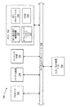
本発明のシステム及び方法は、ソフトウェア(例えば、ファームウェア)、ハードウェア、またはそれらの組み合わせによって実施され得る。制限されない例として、このシステムは、パーソナルコンピュータ(PC;IBM互換性、アップル互換性、または別の)、ワークステーション、ミニコンピュータ、またはメインフレームコンピュータにおけるプロセッサのような、専用または汎用プロセッサによって実行される、実行可能プログラムとしてのソフトウェアを含むコンピュータシステムで実施され得る。本発明のシステム及び方法を実施することが可能な汎用コンピュータの一例が、図7に示されている。図7において、コンピュータシステムは、参照番号700で表示されている。
【0032】
一般に、図7に示すようなハードウェアアーキテクチャに関して、コンピュータシステム700には、プロセッサ712、メモリ714、バイアス回路730、センシング回路732、及び1つまたは複数の入力及び/または出力(I/O)装置716(または周辺装置)が含まれており、それらの全てが、ローカルインターフェイス718を介して通信するように結合されている。ローカルインターフェイス718は、例えば、制限するわけではないが、当該技術において既知のように、1つまたは複数のバスまたは他の有線または無線接続とすることができる。ローカルインターフェイス718は、通信を可能にするために、コントローラ、バッファ(キャッシュ)、ドライバ、中継器、及び受信機のような、簡略化のために省略されている、追加の構成要素を備えることが可能である。さらに、ローカルインターフェイスには、前述のコンポーネント間における適正な通信を可能にするために、アドレス、制御、及び/またはデータの接続を含むことができる。
【0033】
プロセッサ712は、とりわけ、メモリ714に格納されたソフトウェアを実行するためのハードウェア装置である。プロセッサ712は、任意の特注または市販のプロセッサ、中央処理装置(CPU)、コンピュータシステム700に関連したいくつかのプロセッサの中の補助プロセッサ、半導体ベースのマイクロプロセッサ(マイクロチップまたはチップセットの形態をなす)、マクロプロセッサ、またはソフトウェア命令を実行するためのほぼ任意の装置とすることができる。適切な市販のマイクロプロセッサの例は、下記の通りである。すなわち、ヒューレットパッカード社製のPA−RISCシリーズのマイクロプロセッサ、インテル社製の80x86またはペンティアム(R)シリーズのマイクロプロセッサ、IBM社製のPowerPCマイクロプロセッサ、サンマイクロシステムズ社製のSparkマイクロプロセッサ、またはモトローラ社製の68xxxシリーズのマイクロプロセッサである。
【0034】
メモリ714には、揮発性メモリ素子(例えば、ランダムアクセスメモリ(DRAM、SRAM、SDRAM等のようなRAM)及び不揮発性メモリ素子(例えば、磁気ランダムアクセスメモリ(MRAM)、ROM、ハードドライブ、テープ、CDROM等)の任意の1つ、またはそれらの組み合わせを含むことができる。留意すべきは、MRAMは、不揮発性であるが、他のタイプのRAM(すなわち、DRAM、SRAM、SDRAM等)は揮発性であるという点である。従って、用途によっては、揮発性RAMよりも不揮発性MRAMを利用するほうが有利となる場合もある。これにより、MRAMの論理状態を正確に判定することが可能なシステム及び方法の必要性が、さらに増すことになる。
【0035】
また、メモリ714は、電子、磁気、光学、及び/または他のタイプの記憶媒体を組み込むことが可能である。メモリ714が、各種コンポーネントを互いに遠隔配置し、プロセッサ712によってアクセスすることが可能な分散形アーキテクチャを有することができるという点に留意されたい。図7の例では、メモリ714には、MRAMとすることが可能なMTJメモリデバイス724と、独立したROM726とが含まれる。
【0036】
メモリ714内のソフトウェアは、1つまたは複数の別個のプログラムを含むことができ、それらの各々は、論理機能を実施するための実行可能命令の順序つきリストを含む。図7の例において、メモリ714内のソフトウェアには、MTJ読み取り論理回路710及び適切なオペレーティングシステム(O/S)722が含まれる。適切な市販のオペレーティングシステム722の例に関する非網羅的リストは、次の通りである。すなわち、(a)マイクロソフト社から入手可能なWindows(R)オペレーティングシステム、(b)ノベル社から入手可能なネットウェアオペレーティングシステム、(c)アップルコンピュータ社から入手可能なマッキントッシュオペレーティングシステム、(d)ヒューレットパッカード社、サンマイクロシステムズ社、及びAT&T Corporationのような多くのベンダーから購入できるUNIXオペレーティングシステム、(e)インターネットで容易に入手可能なフリーウェアであるLINUXオペレーティングシステム、(f)WindRiver System , Inc. から入手可能なランタイムVxworksオペレーティングシステム、または(g)ハンドヘルドコンピュータまたはパーソナルデジタルアシスタント(PDA)において実施されるような、装置ベースのオペレーティングシステム(例えば、Palm Computing , Inc. から入手可能なPalmOS、及びマイクロソフト社から入手可能なWindows CE(R))である。オペレーティングシステム722は、本質的に、MTJ読み取り論理回路710のような他のコンピュータプログラムの実行を制御し、スケジューリング、入力・出力制御、ファイル及びデータ管理、メモリ管理、並びに通信制御及び関連サービスを提供する。
【0037】
MTJ読み取り論理回路710は、ソースプログラム、実行可能プログラム(目的コード)、スクリプト、または実施されるべき命令セットを構成する他の任意のエンティティとすることができる。ソースプログラムの場合、プログラムは、一般に、O/S722に関連して適正に動作するように、メモリ714内に含めることもできるし、または含めないようにすることも可能な、コンパイラ、アセンブラ、インタープリタ等を介して翻訳される。さらに、MTJ読み取り論理回路710は、(a)データ及びメソッドのクラスを備えるオブジェクト指向プログラミング言語、または(b)例えば、制限するわけではないが、C、C++、Pascal、Basic、Fortran、Cobol、Perl、Java、及びAdaといった、ルーチン、サブルーチン、及び/またはファンクションを備える手順プログラミング言語として書かれることができる。
【0038】
I/O装置716は、例えば、制限するわけではないが、キーボード、マウス、スキャナ、マイクロフォン等の入力装置を含むことができる。さらに、I/O装置716は、例えば、制限するわけではないが、プリンタ、ディスプレイ等のような出力装置を含むこともできる。最後に、I/O装置716は、例えば、制限するわけではないが、変調器/復調器(別の装置、システム、またはネットワークにアクセスするためのモデム)、無線周波数(RF)または他のトランシーバ、電話インターフェイス、ブリッジ、ルータ等のような、入力と出力の両方を伝達する装置をさらに含むこともできる。
【0039】
コンピュータシステム700がPC、ワークステーション等である場合、メモリ714のソフトウェアは、基本入出力システム(BIOS)(簡略化のため省略されている)をさらに含むこともできる。BIOSは、起動時に、ハードウェアを初期化及びテストし、O/S722を起動し、ハードウェア装置間におけるデータの転送を支援する必須のソフトウェアルーチンセットである。BIOSは、ROMに格納されているので、コンピュータシステム700が起動すると、実行され得る。
【0040】
コンピュータシステム700が動作中、プロセッサ712は、メモリ714内に格納されたソフトウェアを実行し、メモリ714との間でデータを伝達し、通常、ソフトウェアに従ってコンピュータシステム700の動作を制御するように構成されている。MTJ読み取り論理回路710及びO/S722は、全体的または部分的に、ただし、後者が一般的であるが、プロセッサ712によって読み取られて、おそらくは、プロセッサ712内にバッファリングされ、その後、実行される。
【0041】
MTJ読み取り論理回路710が、図7に示すようにソフトウェアで実施される場合、任意のコンピュータ関連システムまたはメソッドによる利用、またはそれらに関連した利用に備えて、MTJ読み取り論理回路710が任意のコンピュータ読み取り可能媒体に格納され得るという点に留意すべきである。本明細書に関して、コンピュータ読み取り可能媒体は、コンピュータ関連システムまたはメソッドによる利用、またはそれらに関連した利用に備えて、コンピュータプログラムを収容または格納できる電子、磁気、光学、または他の物理的装置または手段である。MTJ読み取り論理回路710は、命令実行システム、装置、またはデバイスから命令を取り出して、実行することが可能なコンピュータベースのシステム、プロセッサを含むシステム、または他のシステムのような、命令実行システム、装置、またはデバイスによって、またはそれらに関連して利用される、任意のコンピュータ読み取り可能媒体において具現化され得る。本明細書に関して、「コンピュータ読み取り可能媒体」は、命令実行システム、装置、またはデバイスによって、またはそれらに関連して利用されるプログラムを格納し、伝達し、伝搬し、または転送することが可能な任意の手段とすることができる。コンピュータ読み取り可能媒体は、例えば、制限するわけではないが、電子、磁気、光学、電磁気、赤外線、または半導体システム、装置、デバイス、または伝搬媒体とすることができる。コンピュータ読み取り可能媒体のより具体的な例(非網羅的リスト)には、次のようなものが含まれる。すなわち、1つまたは複数のワイヤを備えた電気接続(電子)、携帯式コンピュータディスケット(磁気)、ランダムアクセスメモリ(RAM)(電子)、読み取り専用メモリ(ROM)(電子)、消去可能読み取り専用メモリ(EPROM、EEPROM、またはフラッシュメモリ)(電子)、光ファイバ(光学)、及び携帯式コンパクトディスク読み取り専用メモリ(CDROM)(光学)である。プログラムは、例えば、用紙または他の媒体の光学式走査によって電子的に捕捉され、次に、必要に応じて、適切な態様で、コンパイル、解釈、または別の処理を施し、さらに、コンピュータメモリに格納され得るので、コンピュータ読み取り可能媒体は、プログラムを印刷する用紙または他の適切な媒体とすることさえ可能であるという点に留意されたい。
【0042】
システムがハードウェアで実施される代替の実施形態の場合、バイアス回路730、センシング回路732、及びMTJ読み取り論理回路710のそれぞれは、当該技術においてそれぞれ良く知られている下記の技術の任意の1つ、またはそれらの組み合わせでもって実施され得る。すなわち、データ信号に対する論理機能を実施するための論理ゲートを備えたディスクリートの論理回路、適切な組み合わせ論理ゲートを備えた特定用途向け集積回路(ASIC)、プログラマブルゲートアレイ(PGA)、フィールドプログラマブルゲートアレイ(FPGA)等である。バイアス回路730は、独立型電圧源とし、センシング回路732は電流計とすることさえ可能である。
【0043】
図7に例示された典型的なシステムは、図3に関連して上述したのと同じように機能し、MTJメモリデバイス724における個々のメモリセルにバイアス電圧を印加して、メモリセルに流れる電流を測定できるようにする。図7の典型的な実施形態の1つでは、バイアス回路730が、MTJメモリデバイス724(この例ではMRAMアレイ100である)のビット線132のそれぞれに第1のバイアス電圧Vaを印加する。バイアス回路730は、さらに、アクセスされているメモリセルと交差するワード線130aを除いた、MTJメモリデバイス724のワード線130のそれぞれにも同じバイアス電圧Vaを印加する(例えば、Nのワード線130とNのビット線132を備える対称アレイの場合、バイアス電圧Vaは、Nのビット線全てと、N−1のワード線に印加されることになる)。バイアス回路730は、アクセスされているメモリセルと交差するワード線130aに第2のバイアス電圧Vbを印加する。
【0044】
図7の別の典型的な実施形態において、バイアス回路730は、Nのワード線130全てと、N−1のビット線132に第1のバイアス電圧を印加し、アクセスされているメモリセルと交差するビット線132に第2のバイアス電圧を印加するために使用され得る。
【0045】
これらの実施形態のいずれにおいても、一般に、Va>Vbであり、典型的な実施例の場合、Vbは接地電位であるが、他の適切な電圧を利用することもできる。従って、アクセスされているメモリセルを除いた、アレイ100内の各メモリセルのバイアス電圧は、0(Va−Va)である。アクセスされているメモリセルのバイアス電圧は、(Va−Vb)であり、この結果、アクセスされているメモリセルにセンス電流(Isc)が流れることになる。センシング回路732は、印加されたバイアス電圧(Va−Vb)の結果として、アクセスされているメモリセルに流れるセンス電流(Isc)をモニタするために利用される。
【0046】
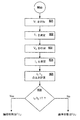
図8は、MTJメモリデバイス724におけるメモリセルの状態を判定するために、図7のMTJ読み取り論理回路710によって実施される論理のフローチャートである。ステップ801では、図7に関連して上述したように、バイアス回路730によって、第1のバイアス電圧(Va1−Vb1=V1)がメモリセルに印加される(例えば、Va1は、アクセスされているメモリセルと交差するビット線132に印加され、Vb1は、アクセスされているメモリセルと交差するワード線130aに印加される)。ステップ802では、第1のバイアス電圧(V1)の結果としてメモリセルに流れる電流(I1)が、センシング回路732によって測定される。ステップ803では、図7に関連して上述したように、バイアス回路730によって、第2のバイアス電圧(Va2−Vb2=V2)がメモリセルに印加される(例えば、Va2は、アクセスされているメモリセルと交差するビット線132に印加され、Vb2は、アクセスされているメモリセルと交差するワード線130aに印加される)。一般に、V2は、約V1/3である。しかしながら、これは、クリティカルな制限ではなく、V2がV1と異なる限りにおいて、V2に関して他の値を用いることもできる。ステップ804では、第2のバイアス電圧(V2)の結果としてメモリセルに流れる電流(I2)は、センシング回路732によって測定される。ステップ805では、第1のバイアス電圧(V1)の結果としてデバイスに流れる電流(I1)と、第2のバイアス電圧(V2)の結果としてデバイスに流れる電流(I2)との比は、方程式I1/I2によって求められる。最後に、ステップ806では、ステップ805において計算された比が、ROM726(図7の)に格納された所定のしきい値(T)と比較される。比(I1/I2)がしきい値(T)より高い場合、メモリセルは、反平行状態(すなわち、論理「0」)であると判定される。比がしきい値(T)未満の場合、メモリセルは、平行状態(すなわち、論理「1」)であると判定される。
【0047】
絶対抵抗測定ではなく、2つのバイアス点間における抵抗曲線の勾配に依存することによって、この測定技術は、バイアス電圧の上昇に対する感応性が他の技術よりも低くなる。従って、本技術は、バイアス電圧が上昇すると、TMRが大幅に低下し、結果として、S/N比が低下することによって制限を受ける、他の技術よりも高いバイアス電圧において、十分なS/N比で動作させることができる。
【0048】
また、上述した測定技術は、破壊読出しを必要としない。従って、この技術は、MTJデバイスの状態を判定するための他のシステム及び方法に比べて、速く動作することができるが、電力消費が少なく、半選択エラーの発生も少ない。さらに、本発明は、アレイ内の個々のメモリセル間に大きい抵抗のばらつきを生じさせる可能性のある、MRAMアレイの生産中に生じる自然変動に適合する。図6に例示したように、本発明は正規化特性を利用するので、セル間のばらつきが最小限に抑えられる。これにより、非破壊しきい値ベースの技術が利用可能になる。さらに、必ず平行構成のままにしておかれるものもあれば、必ず反平行構成のままにしておかれるものもある、アレイ内の1組の基準セルに基づいて動的しきい値(T)を計算することによって、所定のしきい値(T)が独立した不揮発性メモリ(例えば、図7のROM726)に格納される必要性をなくすことができる。しきい値(T)は、基準セルに図8のステップ801〜805を実施し、次に、選択されたセルに対して、ステップ801〜806を実施する際に、ステップ805において、基準セルに関して計算された比をしきい値として利用することによって、動的に導き出されることができる。これは、動作条件が、同時に製作される任意の基準セル及びデータセルに影響を及ぼす他の関係のないプロセス変量と同様に、自動的に補償されるという利点を有する。
【0049】
当業者には明らかなように、上述した本発明の好適な実施形態に対して、本発明の原理からほとんど逸脱することなく、多くの修正及び変更を行うことが可能である。例えば、本明細書において説明された典型的な実施形態は、抵抗対バイアス曲線の二点導関数(two point derivative)を対象としたものであるが(これらの曲線は、どちらの状態においても、この導関数が、定バイアスにおいて状態間で測定される抵抗差とほぼ同じだけ状態間を区別する要素となり得ることを示している)、代替の実施形態は、当該メモリセルの論理状態を判定するために、図6において例示された情報を抽出するための単純なセンシング回路の代わりに、真の導関数回路を利用することができる。MTJデバイスの状態を検出する手段として、印加バイアスに対する抵抗の勾配を用いるという基本概念を利用するために、本発明の他の修正形態及び変更形態を実施することもできる。こうした修正及び変更の全ては、特許請求の範囲に定義された本発明の範囲内に含まれることが意図されている。
【0050】
以下においては、本発明の種々の構成要件の組み合わせからなる例示的な実施形態を示す。
1.磁気トンネル接合(MTJ)メモリデバイスにおけるメモリセルの論理状態を判定するための方法であって、
前記メモリセルに第1のバイアス電圧を印加するステップと、
前記第1のバイアス電圧で前記メモリセルに流れる電流を測定するステップと、
前記第1のバイアス電圧とは異なる第2のバイアス電圧を前記メモリセルに印加するステップと、
前記第2のバイアス電圧で前記メモリセルに流れる電流を測定するステップと、
前記第1のバイアス電圧で前記メモリセルに流れる電流と前記第2のバイアス電圧で前記メモリセルに流れる電流の比を求めるステップと、及び
前記求められた比と所定の値を比較するステップとからなる、方法。
2.前記第2のバイアス電圧が、前記第1のバイアス電圧未満である、上記1に記載の方法。
3.前記第2のバイアス電圧が、前記第1のバイアス電圧より大きい、上記1に記載の方法。
4.前記第2のバイアス電圧が、前記第1のバイアス電圧の約1/3である、上記1に記載の方法。
5.前記所定の値が、
状態が分っている基準MTJメモリセルに第1のバイアス電圧を印加するステップと、
前記第1のバイアス電圧で前記基準セルに流れる電流を測定するステップと、
前記第1のバイアス電圧とは異なる第2のバイアス電圧を前記基準セルに印加するステップと、
前記第2のバイアス電圧で前記基準セルに流れる電流を測定するステップと、及び
前記第1のバイアス電圧で前記基準セルに流れる電流と前記第2のバイアス電圧で前記基準セルに流れる電流との比を求めるステップとによって求められる、
上記1に記載の方法。
6.前記MTJデバイスが、磁気ランダムアクセスメモリ(MRAM)である、上記1に記載の方法。
7.磁気トンネル接合(MTJ)メモリデバイスにおけるメモリセルの論理状態を判定するためのシステムであって、
前記メモリセルに少なくとも2つの異なるバイアス電圧を供給するように構成されたバイアス回路と、
前記少なくとも2つの異なるバイアス電圧のそれぞれで前記メモリセルに流れる電流を測定するように構成されたセンシング回路と、及び
前記少なくとも2つの異なるバイアス電圧の第1の電圧で前記メモリセルに流れる電流と、前記少なくとも2つの異なるバイアス電圧の第2の電圧で前記メモリセルに流れる電流との比を求めて、その比と所定の値を比較するように構成された処理要素とからなる、システム。
8.前記バイアス回路、前記センシング回路、前記処理要素、及び前記MTJデバイスが、特定用途向け集積回路(ASIC)として製作される、上記7に記載のシステム。
9.既知の状態を有する基準MTJメモリセルをさらに含む、上記7に記載のシステム。
10.前記MTJデバイスが、磁気ランダムアクセスメモリ(MRAM)である、上記7に記載のシステム。
【0051】
【発明の効果】
本発明による測定技術によれば、絶対抵抗測定ではなく、2つのバイアス点間における抵抗曲線の勾配に依存することによって、バイアス電圧の上昇に対する感応性が他の技術よりも低くなる。従って、本測定技術によれば、他の技術よりも高いバイアス電圧において、十分なS/N比で動作させることが可能となる。また、本測定技術は、破壊読み出しを必要としないため、他の技術に比べて速く、電力消費が少なく、半選択エラーも少ない。さらに、本測定技術により、MRAMアレイの生産中に生じる自然変動に適合することも可能となる。
【図面の簡単な説明】
【図1】本発明のシステム及び方法の実施形態によって読み取ることが可能な、典型的なMTJメモリデバイスである、簡略化された磁気ランダムアクセスメモリ(MRAM)アレイの平面図である。
【図2A】図1のMRAMアレイの単一メモリセルにおけるデータビットの記憶を例示した図である。
【図2B】図2Aのメモリセルに格納されたデータビットの論理「1」状態を例示した図である。
【図2C】図2Aのメモリセルに格納されたデータビットの論理「0」状態を例示した図である。
【図3】アレイのメモリセルの1つに流れるセンス電流を測定するためのセンシング回路を備えたMTJアレイを例示した略図である。
【図4】ピン留め層に対する磁気記憶層の平行の向き及び反平行の向きについて、印加バイアス電圧の関数として測定されたMTJメモリデバイスの典型的な抵抗値を例示したグラフである。
【図5】図4の抵抗値のトンネル磁気抵抗比(TMR)を例示したグラフである。
【図6】特定の基準電圧における各状態について測定された抵抗値に合わせて正規化された、図4の抵抗値を例示したグラフである。
【図7】MRAMのようなMTJメモリデバイスにおけるメモリセルの状態を判定するためのシステム及び方法を実施するために利用可能なコンピュータシステムの略ブロック図である。
【図8】図7の論理ステップを例示した典型的なフローチャートである。
【符号の説明】
100 MRAMアレイ
120 メモリセル
130 ワード線
132 ビット線
700 コンピュータシステム
712 プロセッサ
714 メモリ
718 ローカルインターフェース
724 MTJメモリデバイス
730 バイアス回路
732 センシング回路[0001]
BACKGROUND OF THE INVENTION
The present invention relates generally to magnetic tunnel junction (MTJ) memory devices, and more particularly to a system and method for determining the logic state of memory cells in an MTJ memory device.
[0002]
[Prior art]
A typical magnetic tunnel junction (MTJ) memory device includes an array of memory cells. Each cell is generally composed of two magnetic thin film layers separated by a dielectric layer. The magnetization of one of the thin film layers can be altered, and the magnetization of the other thin film layer is fixed or “pinned” in a particular direction. A magnetic thin film layer capable of changing magnetization is generally referred to as a “data storage layer”, and a pinned magnetic thin film layer is referred to as a “reference layer”.
[0003]
Conductive traces are generally routed across the array of memory cells. These conductive traces are generally configured to form rows and columns. Conductive traces extending along a row of memory cells are commonly referred to as “word lines” and conductive traces extending along a column of memory cells are generally referred to as “bit lines”. Word lines and bit lines are generally oriented perpendicular to each other. Each memory cell arranged at each intersection of a word line and a bit line stores a bit of information as a magnetization direction.
[0004]
In general, the orientation of magnetization in the data storage layer is aligned along the axis of the data storage layer, commonly referred to as its “easy axis of magnetization”. In general, by applying an external magnetic field, the direction of magnetization in the data storage layer along its easy axis is reversed in parallel or anti-parallel to the direction of magnetization of the reference layer according to the desired logic state.
[0005]
The direction of magnetization of each memory cell is one of two stable directions at any point in time. These two stable orientations, ie parallel and antiparallel, represent the logical values “1” and “0”, respectively. The direction of magnetization of the selected memory cell can be changed by supplying current to the word line and bit line that intersect at the location of the selected memory cell. When combined, the magnetic field generated by the current can switch the magnetization direction of the selected memory cell from parallel to anti-parallel or vice versa.
[0006]
The selected magnetic memory cell is typically written by applying current to specific word lines and bit lines that intersect at the selected magnetic memory cell. In general, applying a current to a specific bit line generates a magnetic field that is substantially straight along the easy axis of the selected magnetic memory cell. A magnetic field that is aligned with the easy axis is generally referred to as a “longitudinal write magnetic field”. By applying a current to a specific word line, a magnetic field generally perpendicular to the easy axis of the selected magnetic memory cell is generated.
[0007]
Generally, only one selected magnetic memory cell receives both longitudinal and vertical write fields simultaneously. Unselected memory cells coupled to the same word line as the selected memory cell generally only receive a vertical write magnetic field. Unselected memory cells coupled to the same bit line as the selected memory cell generally only receive a longitudinal write magnetic field.
[0008]
When word lines and bit lines are combined, they act to switch the direction of magnetization of a selected memory cell (ie, write to a memory cell), so generally word lines and bit lines are collectively referred to as “write”. Called the "line". The write line can also be used to read the logical value stored in the memory cell.
[0009]
FIG. 1 is a plan view illustrating a simplified magnetic random access memory (MRAM) array, which is a typical MTJ memory device.
[0010]
2A, 2B, and 2C generally illustrate the storage of data bits in a
[0011]
The resistance of the
[0012]
FIG. 3 is a schematic diagram of an
[0013]
The logic state of a cell in an MTJ array, such as
[0014]
One way to overcome this ambiguity is to use a data retrieval process known as destructive reading. Destructive readout generally involves (1) first measuring the magnitude of the sense current in a memory cell in response to an applied voltage, and (2) some known (predetermined) state (ie, , “1” or “0”) to the memory cell, and (3) then sensing in the memory cell in response to a second application of the same applied voltage already applied in step 1 The step of measuring the magnitude of the current and (4) whether the logical state of the bit was originally “1” based on the difference in the magnitude of the sense current between the first measurement and the second measurement, Determining whether it was “0”. Furthermore, if the original state of the memory cell determined in step 4 is different from the state written to the cell in step 2, the memory cell must be returned to its original state by a further write operation. For example, when “1” is written in the memory cell in Step 2 and it is determined in Step 4 that the memory cell was originally “0”, the write to the memory cell is performed after the completion of destructive reading. , It must be returned to its original “0” state. On the other hand, when “1” is written in the memory cell in step 2 and it is determined in step 4 that the memory cell was originally “1”, the rewrite operation causes the memory cell to return to its original state. There is no need to return to
[0015]
Although a destructive read process can be used to determine the state of a memory cell, this process has several significant drawbacks. Since the destructive read process may require writing a known value to the memory cell and, in some cases, writing back to its original value, the destructive read process significantly increases read access time. . Further, additional write operations can increase power consumption and reduce the average life of the memory cell.
[0016]
The destructive read process also tends to result in an undesirable condition known as half-select switching. Half-select switching is performed in an MTJ memory array having N × M memory cells (where N and M are greater than or equal to 2) by a write operation on one memory cell to another cell in the array. It can occur when an undesired accidental state change occurs. A memory cell in an MTJ memory array switches its logic state only when it is exposed to both a longitudinal write field and a perpendicular write field, and only one of the longitudinal write field or the perpendicular write field. If it is exposed to but not both, it does not switch its logic state. Thus, the magnitude of the longitudinal and perpendicular write fields is such that the memory cells in the array switch their logic states only when exposed to both the longitudinal and perpendicular write fields. It should be large enough. At the same time, if the magnitude of the longitudinal and vertical write fields is exposed to only one of the longitudinal write field or the perpendicular write field, but not both, the memory in the array It is desirable to be small enough so that the cells do not switch their logic state. However, in some cases, the memory cells in the array change their state even if they are exposed to only one of the longitudinal write field and the perpendicular write field, but not both. It is possible that This undesirable switching of a magnetic memory cell that receives only a longitudinal or vertical write field is commonly referred to as half-select switching.
[0017]
Half-select switching, if it occurs, can cause catastrophic errors during operation of the MTJ memory array. For example, by trying to switch the logic state of the first memory cell in an array from “0” to “1”, the logic state of the second memory cell in the array is also erroneously changed from “0” to “1”. Can cause accidental and undesirable effects. The half-select switching problem may be mitigated by improvements in magnetic process engineering, but is not expected to be completely eliminated. Therefore, it is preferable to keep the number of write operations to a minimum in order to minimize the possibility of half-select switching. However, the destructive read process requires at least one extra write operation for each memory cell to be read, and if the memory cell must be rewritten to its original state, two extra writes are required. Write operations are potentially required. Thus, the destructive read process increases the likelihood of half-select switching.
[0018]
[Problems to be solved by the invention]
Accordingly, there is a need for a system and method for determining the logic state of a memory cell in a magnetic tunnel junction (MTJ) memory device that overcomes the deficiencies and drawbacks described above.
[0019]
[Means for Solving the Problems]
The present invention is a system and method for determining a logic state of a memory cell in an MTJ memory device based on a ratio of currents flowing in a magnetic tunnel junction (MTJ) memory device in response to at least two different bias voltages. is there. The system includes a bias circuit or voltage supply for applying at least two different bias voltages to the memory cells of the MTJ memory device, and a sensing circuit or current for measuring the current flowing through the memory cells at each applied bias voltage. A measurement device and a processing element configured to calculate a ratio of the current measured at each applied bias voltage and compare the measured current ratio at each applied bias voltage with a predetermined value are included. .
[0020]
The present invention is different from the step of applying a first bias voltage to a memory cell of an MTJ memory device, the step of measuring a current flowing through the memory cell at the first bias voltage, and the first bias voltage of the memory cell. Applying a second bias voltage; measuring a current flowing through the memory cell at the second bias voltage; flowing through the memory cell at the first bias voltage; and flowing through the memory cell at the second bias voltage. It can also be characterized as a method comprising the steps of determining a ratio with current and comparing the determined ratio of current with a predetermined value.
[0021]
Other features and advantages of the present invention will become apparent to those skilled in the art upon review of the following drawings and detailed description. All such features and advantages are intended to be included within the scope of this invention as defined in the claims.
[0022]
The invention as defined in the claims can be better understood with reference to the following drawings. The components in the drawings need not be to scale relative to each other, but instead focus on clearly illustrating the principles of the invention.
[0023]
DETAILED DESCRIPTION OF THE INVENTION
In the following detailed description of the invention, reference is made to the accompanying drawings that form a part hereof, and which are shown by way of illustration of specific embodiments in which the invention may be practiced. Of course, other embodiments may be utilized and structural or logical changes may be made without departing from the scope of the invention. The following detailed description is, therefore, not to be taken in a limiting sense, and the scope of the present invention is defined by the appended claims. For example, the present invention is described below as applied to a magnetic random access memory (MRAM) array, but in general, but not limited to, MTJ as a storage element including MRAM, EEPROM, flip-flop, shift register, etc. It can be applied to any device using memory cells.
[0024]
Referring now to the drawings wherein like reference numerals represent corresponding components throughout the several views, FIG. 4 illustrates the parallelism of the magnetic storage layer (R p ) And antiparallel (R ap ) Is a graphical illustration of a typical resistance value of a typical MTJ memory cell measured as a function of applied bias voltage. This data is common for ferromagnetic, insulator, and ferromagnetic (FM-I-FM) MTJ devices.
[0025]
As illustrated in FIG. 4, the slope of the resistance versus applied bias curve in the anti-parallel state (curve 402) is considerably larger than in the parallel state (curve 404). As known to those skilled in the art, this is generally consistent with MTJ devices, quantified by determining the MTJ device's tunneling magnetoresistance ratio (TMR), as described below in connection with FIG. Characteristics.
[0026]
FIG. 5 shows the applied bias voltage (V bias 4 is a graph illustrating the tunnel magnetoresistance ratio (TMR) of the resistance values in FIG. TMR is the difference between the antiparallel resistance and the parallel resistance (R ap -R p ) To parallel resistance (R p ) Divided by. Therefore, TMR = (R ap -R p ) / R p . As illustrated by
[0027]
The fact that the TMR ratio decreases with increasing applied bias (as illustrated in FIG. 5) has generally been regarded as a disadvantageous characteristic of MTJ devices. Therefore, much effort has been made to reduce the sensitivity of the TMR ratio to the applied bias. However, as theoretically apparent, such sensitivity is a fundamental property of FM-I-FM MTJ devices, so it is unlikely to eliminate this sensitivity. As described below, the present invention uses this characteristic to determine the state of the MTJ memory device.
[0028]
FIG. 6 is a graph illustrating the resistance values of FIG. 4 normalized to the resistance values measured for each state at a specific reference voltage. FIG. 6 is derived from the same raw data that was used to create FIGS. In FIG. 6, the resistance data is normalized for each state according to the resistance value that the MTJ device has in that state with an applied bias of 1V. For the example of FIG. 6, 1V was selected, but the data can be normalized to the resistance at any suitable applied voltage. By normalizing the data for each memory cell to the value of that memory cell at a particular reference voltage, variability between the memory cells in the array is minimized. In other words, there can be a significant degree of variation between the absolute resistance values of different memory cells in the array, but the normalized values are generally much more consistent.
[0029]
Referring to FIG. 6,
[0030]
Rather than using a single resistance measurement to determine the logic state of a memory cell in an MTJ memory array, as described above in connection with FIG. 3, the system and method of the present invention uses FIGS. In order to more accurately determine the logic state of the memory cell, the rate of change of the resistance of the memory cell is determined as a function of the applied voltage using at least two measurements, as will be described later in connection with FIG.
[0031]
The systems and methods of the present invention may be implemented by software (eg, firmware), hardware, or a combination thereof. By way of non-limiting example, the system is implemented by a dedicated or general purpose processor, such as a processor in a personal computer (PC; IBM compatible, Apple compatible, or another), workstation, minicomputer, or mainframe computer. It can be implemented on a computer system that includes software as an executable program. An example of a general purpose computer capable of implementing the system and method of the present invention is shown in FIG. In FIG. 7, the computer system is indicated by
[0032]
In general, with respect to a hardware architecture such as that shown in FIG. 7, the
[0033]
The
[0034]
The memory 714 includes volatile memory elements (eg, random access memory (RAM such as DRAM, SRAM, SDRAM, etc.) and non-volatile memory elements (eg, magnetic random access memory (MRAM), ROM, hard drive, tape, CDRAM, etc.) can be included, or combinations thereof Note that MRAM is non-volatile, but other types of RAM (ie, DRAM, SRAM, SDRAM, etc.) are volatile. Therefore, in some applications, it may be advantageous to use a non-volatile MRAM rather than a volatile RAM, so that the system can accurately determine the logical state of the MRAM. And the need for methods will increase further.
[0035]
The memory 714 can also incorporate electronic, magnetic, optical, and / or other types of storage media. Note that the memory 714 can have a distributed architecture in which various components can be remotely located and accessed by the
[0036]
The software in memory 714 can include one or more separate programs, each of which includes an ordered list of executable instructions for performing logic functions. In the example of FIG. 7, the software in memory 714 includes MTJ read logic 710 and an appropriate operating system (O / S) 722. A non-exhaustive list for examples of suitable
[0037]
The MTJ read logic 710 can be a source program, an executable program (object code), a script, or any other entity that makes up the instruction set to be implemented. For source programs, the program is typically a compiler, assembler, interpreter that may or may not be included in memory 714 to operate properly in connection with O /
[0038]
The I /
[0039]
If the
[0040]
While the
[0041]
If the MTJ read logic 710 is implemented in software as shown in FIG. 7, the MTJ read logic 710 may be read by any computer-related system or method for use by or associated with any computer-related system or method. It should be noted that it can be stored on a possible medium. In the context of this specification, a computer-readable medium is an electronic, magnetic, optical, or other physical device or means capable of containing or storing a computer program for use by or in connection with a computer-related system or method. It is. The MTJ read logic 710 is an instruction execution system, apparatus, such as a computer-based system, a system including a processor, or other system that can retrieve and execute instructions from the instruction execution system, apparatus, or device. , Or any computer-readable medium utilized by or in connection with the device. In the context of this specification, a “computer-readable medium” is capable of storing, transmitting, propagating, or transferring a program utilized by or in connection with an instruction execution system, apparatus, or device. Any means can be used. The computer readable medium can be, for example but not limited to, an electronic, magnetic, optical, electromagnetic, infrared, or semiconductor system, apparatus, device, or propagation medium. More specific examples (non-exhaustive list) of computer readable media include: That is, electrical connection (electronic) with one or more wires, portable computer diskette (magnetic), random access memory (RAM) (electronic), read-only memory (ROM) (electronic), erasable read-only memory (EPROM, EEPROM, or flash memory) (electronic), optical fiber (optical), and portable compact disk read only memory (CDROM) (optical). The program is captured electronically, for example, by optical scanning of paper or other media, then compiled, interpreted, or otherwise processed in an appropriate manner as necessary, and further stored in computer memory. It should be noted that the computer readable medium can even be a paper or other suitable medium on which the program is printed, since it can be stored.
[0042]
In an alternative embodiment where the system is implemented in hardware, each of
[0043]
The exemplary system illustrated in FIG. 7 functions in the same manner as described above in connection with FIG. 3 and applies a bias voltage to the individual memory cells in the MTJ memory device 724 to provide current flow through the memory cells. Can be measured. In one exemplary embodiment of FIG. 7, a
[0044]
In another exemplary embodiment of FIG. 7,
[0045]
In any of these embodiments, generally V a > V b And in the exemplary embodiment V b Is a ground potential, but other suitable voltages may be used. Accordingly, the bias voltage of each memory cell in the
[0046]
FIG. 8 is a flowchart of the logic performed by the MTJ read logic circuit 710 of FIG. 7 to determine the state of memory cells in the MTJ memory device 724. In
[0047]
By relying on the slope of the resistance curve between two bias points rather than an absolute resistance measurement, this measurement technique is less sensitive to increased bias voltage than other techniques. Therefore, the present technique significantly reduces TMR as the bias voltage increases, resulting in limitations due to a decrease in the S / N ratio. Can be operated at a ratio.
[0048]
Also, the measurement technique described above does not require destructive readout. Thus, this technique can operate faster than other systems and methods for determining the state of an MTJ device, but consumes less power and produces fewer half-select errors. Furthermore, the present invention is compatible with natural variations that occur during the production of MRAM arrays that can cause large resistance variations between individual memory cells in the array. As illustrated in FIG. 6, since the present invention uses the normalization characteristic, the variation between cells is minimized. This makes non-destructive threshold based techniques available. In addition, some will always remain in a parallel configuration, while others will always remain in an anti-parallel configuration. By calculating, it is possible to eliminate the need for the predetermined threshold value (T) to be stored in an independent non-volatile memory (eg,
[0049]
It will be apparent to those skilled in the art that many modifications and variations can be made to the preferred embodiments of the invention described above without departing substantially from the principles of the invention. For example, the exemplary embodiments described herein are directed to the two point derivative of a resistance versus bias curve (which, in either state, An alternative embodiment determines the logic state of the memory cell, indicating that this derivative can be a factor that distinguishes between states by as much as the resistance difference measured between states at constant bias). Thus, a true derivative circuit can be utilized instead of a simple sensing circuit for extracting the information illustrated in FIG. Other modifications and variations of the present invention can also be implemented to take advantage of the basic concept of using a resistance gradient relative to the applied bias as a means of detecting the state of the MTJ device. All such modifications and changes are intended to be included within the scope of the present invention as defined in the appended claims.
[0050]
In the following, exemplary embodiments consisting of combinations of various components of the present invention are shown.
1. A method for determining a logic state of a memory cell in a magnetic tunnel junction (MTJ) memory device, comprising:
Applying a first bias voltage to the memory cell;
Measuring a current flowing through the memory cell at the first bias voltage;
Applying a second bias voltage different from the first bias voltage to the memory cell;
Measuring a current flowing through the memory cell at the second bias voltage;
Obtaining a ratio of a current flowing through the memory cell at the first bias voltage to a current flowing through the memory cell at the second bias voltage; and
Comparing the determined ratio with a predetermined value.
2. The method of claim 1, wherein the second bias voltage is less than the first bias voltage.
3. The method of claim 1, wherein the second bias voltage is greater than the first bias voltage.
4). The method of claim 1, wherein the second bias voltage is about 3 of the first bias voltage.
5). The predetermined value is
Applying a first bias voltage to a reference MTJ memory cell whose state is known;
Measuring a current flowing through the reference cell at the first bias voltage;
Applying a second bias voltage different from the first bias voltage to the reference cell;
Measuring a current flowing through the reference cell at the second bias voltage; and
Obtaining a ratio of a current flowing through the reference cell at the first bias voltage and a current flowing through the reference cell at the second bias voltage.
2. The method according to 1 above.
6). The method of claim 1, wherein the MTJ device is a magnetic random access memory (MRAM).
7). A system for determining a logic state of a memory cell in a magnetic tunnel junction (MTJ) memory device, comprising:
A bias circuit configured to supply at least two different bias voltages to the memory cell;
A sensing circuit configured to measure a current flowing through the memory cell at each of the at least two different bias voltages; and
Determining a ratio between a current flowing through the memory cell at a first voltage of the at least two different bias voltages and a current flowing through the memory cell at a second voltage of the at least two different bias voltages; A system comprising processing elements configured to compare predetermined values.
8). The system of claim 7, wherein the bias circuit, the sensing circuit, the processing element, and the MTJ device are fabricated as an application specific integrated circuit (ASIC).
9. The system of claim 7, further comprising a reference MTJ memory cell having a known state.
10. The system of claim 7, wherein the MTJ device is a magnetic random access memory (MRAM).
[0051]
【The invention's effect】
The measurement technique according to the present invention is less sensitive to increasing bias voltage than other techniques by relying on the slope of the resistance curve between two bias points rather than absolute resistance measurements. Therefore, according to this measurement technique, it is possible to operate with a sufficient S / N ratio at a higher bias voltage than other techniques. Also, since this measurement technique does not require destructive readout, it is faster, consumes less power, and has fewer half-select errors than other techniques. In addition, this measurement technique also allows for adaptation to natural variations that occur during the production of MRAM arrays.
[Brief description of the drawings]
FIG. 1 is a plan view of a simplified magnetic random access memory (MRAM) array, which is an exemplary MTJ memory device that can be read by embodiments of the system and method of the present invention.
2A illustrates the storage of data bits in a single memory cell of the MRAM array of FIG.
2B illustrates a logic “1” state of data bits stored in the memory cell of FIG. 2A.
2C illustrates a logic “0” state of data bits stored in the memory cell of FIG. 2A.
FIG. 3 is a schematic diagram illustrating an MTJ array with a sensing circuit for measuring a sense current flowing in one of the memory cells of the array.
FIG. 4 is a graph illustrating a typical resistance value of an MTJ memory device measured as a function of applied bias voltage for the parallel orientation and antiparallel orientation of the magnetic storage layer relative to the pinned layer.
5 is a graph illustrating the tunnel magnetoresistance ratio (TMR) of the resistance value of FIG. 4;
6 is a graph illustrating the resistance values of FIG. 4 normalized to the resistance values measured for each state at a particular reference voltage.
FIG. 7 is a schematic block diagram of a computer system that can be used to implement a system and method for determining the state of a memory cell in an MTJ memory device such as an MRAM.
FIG. 8 is an exemplary flowchart illustrating the logical steps of FIG.
[Explanation of symbols]
100 MRAM array
120 memory cells
130 word lines
132 bit lines
700 computer system
712 processor
714 memory
718 Local interface
724 MTJ memory device
730 Bias circuit
732 Sensing circuit
Claims (5)
前記メモリセルに第1のバイアス電圧を印加するステップと、
前記第1のバイアス電圧で前記メモリセルに流れる電流を測定するステップと、
前記第1のバイアス電圧とは異なる第2のバイアス電圧を前記メモリセルに印加するステップと、
前記第2のバイアス電圧で前記メモリセルに流れる電流を測定するステップと、
前記第1のバイアス電圧で前記メモリセルに流れる電流と前記第2のバイアス電圧で前記メモリセルに流れる電流の比を求めるステップと、及び
前記求められた比と所定の値を比較するステップとからなる、方法。A method for determining a logic state of a memory cell in a magnetic tunnel junction (MTJ) memory device, comprising:
Applying a first bias voltage to the memory cell;
Measuring a current flowing through the memory cell at the first bias voltage;
Applying a second bias voltage different from the first bias voltage to the memory cell;
Measuring a current flowing through the memory cell at the second bias voltage;
Obtaining a ratio of a current flowing through the memory cell with the first bias voltage and a current flowing through the memory cell with the second bias voltage; and comparing the obtained ratio with a predetermined value. Become a way.
前記メモリセルに少なくとも2つの異なるバイアス電圧を供給するように構成されたバイアス回路と、
前記少なくとも2つの異なるバイアス電圧のそれぞれで前記メモリセルに流れる電流を測定するように構成されたセンシング回路と、及び
前記少なくとも2つの異なるバイアス電圧の第1の電圧で前記メモリセルに流れる電流と、前記少なくとも2つの異なるバイアス電圧の第2の電圧で前記メモリセルに流れる電流との比を求めて、その比と所定の値を比較するように構成された処理要素とからなる、システム。A system for determining a logic state of a memory cell in a magnetic tunnel junction (MTJ) memory device, comprising:
A bias circuit configured to supply at least two different bias voltages to the memory cell;
A sensing circuit configured to measure a current flowing through the memory cell at each of the at least two different bias voltages; and a current flowing through the memory cell at a first voltage of the at least two different bias voltages; A system comprising: a processing element configured to determine a ratio of a current flowing through the memory cell at a second voltage of the at least two different bias voltages and compare the ratio to a predetermined value.
Applications Claiming Priority (2)
| Application Number | Priority Date | Filing Date | Title |
|---|---|---|---|
| US10/055,299 US6650562B2 (en) | 2002-01-23 | 2002-01-23 | System and method for determining the logic state of a memory cell in a magnetic tunnel junction memory device |
| US10/055299 | 2002-01-23 |
Publications (3)
| Publication Number | Publication Date |
|---|---|
| JP2003228993A JP2003228993A (en) | 2003-08-15 |
| JP2003228993A5 JP2003228993A5 (en) | 2005-05-19 |
| JP3958692B2 true JP3958692B2 (en) | 2007-08-15 |
Family
ID=21996962
Family Applications (1)
| Application Number | Title | Priority Date | Filing Date |
|---|---|---|---|
| JP2003013288A Expired - Fee Related JP3958692B2 (en) | 2002-01-23 | 2003-01-22 | System and method for determining the logic state of a memory cell in a magnetic tunnel junction memory device |
Country Status (3)
| Country | Link |
|---|---|
| US (2) | US6650562B2 (en) |
| JP (1) | JP3958692B2 (en) |
| DE (1) | DE10301305A1 (en) |
Families Citing this family (30)
| Publication number | Priority date | Publication date | Assignee | Title |
|---|---|---|---|---|
| US6597600B2 (en) * | 2001-08-27 | 2003-07-22 | Micron Technology, Inc. | Offset compensated sensing for magnetic random access memory |
| US6650562B2 (en) * | 2002-01-23 | 2003-11-18 | Hewlett-Packard Development Company, L.P. | System and method for determining the logic state of a memory cell in a magnetic tunnel junction memory device |
| US6707084B2 (en) * | 2002-02-06 | 2004-03-16 | Micron Technology, Inc. | Antiferromagnetically stabilized pseudo spin valve for memory applications |
| US7116576B2 (en) * | 2003-07-07 | 2006-10-03 | Hewlett-Packard Development Company, L.P. | Sensing the state of a storage cell including a magnetic element |
| US20060004652A1 (en) * | 2004-06-22 | 2006-01-05 | Greig Russell H Jr | Loan option algorithm adaptable to fully variable option loans and fixed option loans |
| KR100669363B1 (en) * | 2004-10-26 | 2007-01-16 | 삼성전자주식회사 | Reading Scheme Of Memory Device |
| TWI337355B (en) * | 2007-06-29 | 2011-02-11 | Ind Tech Res Inst | Simulating circuit for simulating a toggle magnetic tunneling junction element |
| US7602649B2 (en) * | 2007-09-04 | 2009-10-13 | Qimonda Ag | Method of operating an integrated circuit for reading the logical state of a memory cell |
| US8659852B2 (en) * | 2008-04-21 | 2014-02-25 | Seagate Technology Llc | Write-once magentic junction memory array |
| US7852663B2 (en) | 2008-05-23 | 2010-12-14 | Seagate Technology Llc | Nonvolatile programmable logic gates and adders |
| US7855911B2 (en) | 2008-05-23 | 2010-12-21 | Seagate Technology Llc | Reconfigurable magnetic logic device using spin torque |
| US8116123B2 (en) | 2008-06-27 | 2012-02-14 | Seagate Technology Llc | Spin-transfer torque memory non-destructive self-reference read method |
| US7881098B2 (en) | 2008-08-26 | 2011-02-01 | Seagate Technology Llc | Memory with separate read and write paths |
| US7985994B2 (en) | 2008-09-29 | 2011-07-26 | Seagate Technology Llc | Flux-closed STRAM with electronically reflective insulative spacer |
| US8169810B2 (en) | 2008-10-08 | 2012-05-01 | Seagate Technology Llc | Magnetic memory with asymmetric energy barrier |
| US8039913B2 (en) | 2008-10-09 | 2011-10-18 | Seagate Technology Llc | Magnetic stack with laminated layer |
| US8089132B2 (en) | 2008-10-09 | 2012-01-03 | Seagate Technology Llc | Magnetic memory with phonon glass electron crystal material |
| US8045366B2 (en) | 2008-11-05 | 2011-10-25 | Seagate Technology Llc | STRAM with composite free magnetic element |
| US8043732B2 (en) | 2008-11-11 | 2011-10-25 | Seagate Technology Llc | Memory cell with radial barrier |
| US7826181B2 (en) | 2008-11-12 | 2010-11-02 | Seagate Technology Llc | Magnetic memory with porous non-conductive current confinement layer |
| US8289756B2 (en) | 2008-11-25 | 2012-10-16 | Seagate Technology Llc | Non volatile memory including stabilizing structures |
| US7826259B2 (en) | 2009-01-29 | 2010-11-02 | Seagate Technology Llc | Staggered STRAM cell |
| US9728240B2 (en) * | 2009-04-08 | 2017-08-08 | Avalanche Technology, Inc. | Pulse programming techniques for voltage-controlled magnetoresistive tunnel junction (MTJ) |
| JP2011008861A (en) * | 2009-06-25 | 2011-01-13 | Sony Corp | Memory |
| US7999338B2 (en) | 2009-07-13 | 2011-08-16 | Seagate Technology Llc | Magnetic stack having reference layers with orthogonal magnetization orientation directions |
| CN103081018B (en) * | 2010-08-31 | 2016-06-22 | 国际商业机器公司 | Location mode in phase transition storage is determined |
| US9111613B2 (en) * | 2012-07-12 | 2015-08-18 | The Regents Of The University Of Michigan | Adaptive reading of a resistive memory |
| US9153307B2 (en) * | 2013-09-09 | 2015-10-06 | Qualcomm Incorporated | System and method to provide a reference cell |
| US8891326B1 (en) * | 2013-09-11 | 2014-11-18 | Avalanche Technology, Inc. | Method of sensing data in magnetic random access memory with overlap of high and low resistance distributions |
| US9721639B1 (en) | 2016-06-21 | 2017-08-01 | Micron Technology, Inc. | Memory cell imprint avoidance |
Family Cites Families (8)
| Publication number | Priority date | Publication date | Assignee | Title |
|---|---|---|---|---|
| US6169689B1 (en) * | 1999-12-08 | 2001-01-02 | Motorola, Inc. | MTJ stacked cell memory sensing method and apparatus |
| US6185143B1 (en) * | 2000-02-04 | 2001-02-06 | Hewlett-Packard Company | Magnetic random access memory (MRAM) device including differential sense amplifiers |
| US6426907B1 (en) * | 2001-01-24 | 2002-07-30 | Infineon Technologies North America Corp. | Reference for MRAM cell |
| US6650562B2 (en) * | 2002-01-23 | 2003-11-18 | Hewlett-Packard Development Company, L.P. | System and method for determining the logic state of a memory cell in a magnetic tunnel junction memory device |
| US6639839B1 (en) * | 2002-05-21 | 2003-10-28 | Macronix International Co., Ltd. | Sensing method for EEPROM refresh scheme |
| US6590804B1 (en) * | 2002-07-16 | 2003-07-08 | Hewlett-Packard Development Company, L.P. | Adjustable current mode differential amplifier |
| US6674679B1 (en) * | 2002-10-01 | 2004-01-06 | Hewlett-Packard Development Company, L.P. | Adjustable current mode differential amplifier for multiple bias point sensing of MRAM having equi-potential isolation |
| US6954373B2 (en) * | 2003-06-27 | 2005-10-11 | Hewlett-Packard Development Company, L.P. | Apparatus and method for determining the logic state of a magnetic tunnel junction memory device |
-
2002
- 2002-01-23 US US10/055,299 patent/US6650562B2/en not_active Expired - Lifetime
-
2003
- 2003-01-15 DE DE10301305A patent/DE10301305A1/en not_active Ceased
- 2003-01-22 JP JP2003013288A patent/JP3958692B2/en not_active Expired - Fee Related
- 2003-09-12 US US10/660,831 patent/US6999334B2/en not_active Expired - Lifetime
Also Published As
| Publication number | Publication date |
|---|---|
| US6650562B2 (en) | 2003-11-18 |
| US6999334B2 (en) | 2006-02-14 |
| US20030137864A1 (en) | 2003-07-24 |
| US20050099855A1 (en) | 2005-05-12 |
| DE10301305A1 (en) | 2003-08-14 |
| JP2003228993A (en) | 2003-08-15 |
Similar Documents
| Publication | Publication Date | Title |
|---|---|---|
| JP3958692B2 (en) | System and method for determining the logic state of a memory cell in a magnetic tunnel junction memory device | |
| US6188615B1 (en) | MRAM device including digital sense amplifiers | |
| US10346088B2 (en) | Method and apparatus for per-deck erase verify and dynamic inhibit in 3d NAND | |
| US7916515B2 (en) | Non-volatile memory read/write verify | |
| US6762952B2 (en) | Minimizing errors in a magnetoresistive solid-state storage device | |
| US9047967B2 (en) | Data-masked analog and digital read for resistive memories | |
| JP2003022668A (en) | Resistive cross point memory with on-chip amplifier calibration method | |
| US20210265003A1 (en) | Test method for memory device, operating method of test device testing memory device, and memory device with self-test function | |
| US11488641B2 (en) | Memory device including variable reference resistor and method of calibrating the variable reference resistor | |
| US10734048B2 (en) | Sensing memory cells using array control lines | |
| US6954373B2 (en) | Apparatus and method for determining the logic state of a magnetic tunnel junction memory device | |
| US11074151B2 (en) | Processor having embedded non-volatile random access memory to support processor monitoring software | |
| US10056126B1 (en) | Magnetic tunnel junction based memory device | |
| US6898134B2 (en) | Systems and methods for sensing a memory element | |
| US20090046510A1 (en) | Apparatus and method for multi-bit programming | |
| US20230214148A1 (en) | Redundant computing across planes | |
| JP2006277822A (en) | Magnetic random access memory and its operating method | |
| US6842364B1 (en) | Memory cell strings in a resistive cross point memory cell array | |
| JP4101210B2 (en) | Retrieval of data stored in magnetic integrated memory | |
| KR20110060851A (en) | Stored multi-bit data characterized by multiple-dimensional memory state | |
| US11621026B2 (en) | Write driver with magnetic field compensation | |
| US11935615B2 (en) | Thermometer sample and hold design for non-volatile memory | |
| US20240136000A1 (en) | Compact digital thermometer in a memory device | |
| CN113805027A (en) | Method, system and readable storage medium for testing semiconductor device |
Legal Events
| Date | Code | Title | Description |
|---|---|---|---|
| A521 | Request for written amendment filed |
Free format text: JAPANESE INTERMEDIATE CODE: A523 Effective date: 20040716 |
|
| A621 | Written request for application examination |
Free format text: JAPANESE INTERMEDIATE CODE: A621 Effective date: 20040716 |
|
| A977 | Report on retrieval |
Free format text: JAPANESE INTERMEDIATE CODE: A971007 Effective date: 20070403 |
|
| TRDD | Decision of grant or rejection written | ||
| A01 | Written decision to grant a patent or to grant a registration (utility model) |
Free format text: JAPANESE INTERMEDIATE CODE: A01 Effective date: 20070410 |
|
| A61 | First payment of annual fees (during grant procedure) |
Free format text: JAPANESE INTERMEDIATE CODE: A61 Effective date: 20070510 |
|
| R150 | Certificate of patent or registration of utility model |
Ref document number: 3958692 Country of ref document: JP Free format text: JAPANESE INTERMEDIATE CODE: R150 Free format text: JAPANESE INTERMEDIATE CODE: R150 |
|
| FPAY | Renewal fee payment (event date is renewal date of database) |
Free format text: PAYMENT UNTIL: 20100518 Year of fee payment: 3 |
|
| S111 | Request for change of ownership or part of ownership |
Free format text: JAPANESE INTERMEDIATE CODE: R313113 |
|
| FPAY | Renewal fee payment (event date is renewal date of database) |
Free format text: PAYMENT UNTIL: 20100518 Year of fee payment: 3 |
|
| R350 | Written notification of registration of transfer |
Free format text: JAPANESE INTERMEDIATE CODE: R350 |
|
| FPAY | Renewal fee payment (event date is renewal date of database) |
Free format text: PAYMENT UNTIL: 20100518 Year of fee payment: 3 |
|
| FPAY | Renewal fee payment (event date is renewal date of database) |
Free format text: PAYMENT UNTIL: 20110518 Year of fee payment: 4 |
|
| R250 | Receipt of annual fees |
Free format text: JAPANESE INTERMEDIATE CODE: R250 |
|
| FPAY | Renewal fee payment (event date is renewal date of database) |
Free format text: PAYMENT UNTIL: 20120518 Year of fee payment: 5 |
|
| R250 | Receipt of annual fees |
Free format text: JAPANESE INTERMEDIATE CODE: R250 |
|
| FPAY | Renewal fee payment (event date is renewal date of database) |
Free format text: PAYMENT UNTIL: 20120518 Year of fee payment: 5 |
|
| FPAY | Renewal fee payment (event date is renewal date of database) |
Free format text: PAYMENT UNTIL: 20130518 Year of fee payment: 6 |
|
| R250 | Receipt of annual fees |
Free format text: JAPANESE INTERMEDIATE CODE: R250 |
|
| R250 | Receipt of annual fees |
Free format text: JAPANESE INTERMEDIATE CODE: R250 |
|
| R250 | Receipt of annual fees |
Free format text: JAPANESE INTERMEDIATE CODE: R250 |
|
| R250 | Receipt of annual fees |
Free format text: JAPANESE INTERMEDIATE CODE: R250 |
|
| R250 | Receipt of annual fees |
Free format text: JAPANESE INTERMEDIATE CODE: R250 |
|
| R250 | Receipt of annual fees |
Free format text: JAPANESE INTERMEDIATE CODE: R250 |
|
| R250 | Receipt of annual fees |
Free format text: JAPANESE INTERMEDIATE CODE: R250 |
|
| R250 | Receipt of annual fees |
Free format text: JAPANESE INTERMEDIATE CODE: R250 |
|
| R250 | Receipt of annual fees |
Free format text: JAPANESE INTERMEDIATE CODE: R250 |
|
| R250 | Receipt of annual fees |
Free format text: JAPANESE INTERMEDIATE CODE: R250 |
|
| LAPS | Cancellation because of no payment of annual fees |