JP3956566B2 - Digital signal recording method and information recording medium - Google Patents
Digital signal recording method and information recording medium Download PDFInfo
- Publication number
- JP3956566B2 JP3956566B2 JP2000032727A JP2000032727A JP3956566B2 JP 3956566 B2 JP3956566 B2 JP 3956566B2 JP 2000032727 A JP2000032727 A JP 2000032727A JP 2000032727 A JP2000032727 A JP 2000032727A JP 3956566 B2 JP3956566 B2 JP 3956566B2
- Authority
- JP
- Japan
- Prior art keywords
- frame
- frames
- bit
- sector
- synchronization
- Prior art date
- Legal status (The legal status is an assumption and is not a legal conclusion. Google has not performed a legal analysis and makes no representation as to the accuracy of the status listed.)
- Expired - Lifetime
Links
Images


Description
【0001】
【発明の属する技術分野】
本発明は、ディジタル信号記録方法、及び情報記録媒体に関し、特に記録情報に対し変調処理を行い、同期信号を付加することで生成した同期フレームに対するディジタル信号をディスク記録媒体に上に記録ピット(マーク)として記録する場合のディジタル信号記録方法、及び情報記録媒体に関する。
【0002】
【従来の技術】
記録情報に対し変調処理を行った後の一定量のデータ単位でその先頭を示す同期信号を付加することで同期フレームを構成し、その同期フレームに対するディジタル信号をディスク記録媒体上の記録ピット(マーク)として記録するディスク記録媒体の一例としてDVD(Digital Versatile Disc)が挙げられる。このDVDについてのディジタル信号の生成方法は「NIKKEI ELECTRONICS BOOKS データ圧縮とディジタル変調 98年度版 pp.121〜123」、「特開平9−162857号 ディジタルデータの伝送方法」の公知例にその技術が記載されている。この技術について図2、図3を用いて説明する。図2において、ディスクへの記録単位であるセクタに格納する2キロ(2048)バイトの記録情報にディスク上の記録アドレスを示すセクタID番号をはじめとするセクタ固有の情報などを付加した配列、172バイト×12行でセクタデータを構成し、次にセクタデータ16個を集めた172バイト×12行×16セクタ=32キロバイトの配列に対して、縦系列に対してPO訂正符号16バイト、横系列に対してPI訂正符号10バイトを付加することで訂正ブロックを構成し、更にPO訂正符号を含む行データについては12行単位のセクタデータ毎に1行を分散することでインタリーブ配列を構成する。更にインタリーブ配列に含まれる行データに対し8−16変調処理、同期信号の付加を行うことで1行につき同期フレーム2個を生成する。生成した同期フレームに対する8種類の同期信号SY0〜SY7の配置方法については、セクタID番号を含む先頭同期フレームからPO訂正符号に対する同期フレーム26フレームに対し、先頭同期フレームにSY0の同期信号を一つ配置し、それ以降の同期フレームに対してはSY5、SY1、SY5、・・・の順に配置される。更に同期信号の配置順、SY0、SY5、SY1、SY5、・・・に従い同期フレームに対するディジタル信号をディスク上に連続的に記録する。8−16変調処理についてはRLL(Run Length Limited)符号化方法が用いられており、Tをディスク上の記録ビット(マーク)間隔の単位とすると、最小ラン長d=2T、最大ラン長k=10Tのラン長制限を満たすように行データに含まれる8ビットデータを16ビット(1ワード)のコードワードに変換する。行データに対する同期フレームの数については、同期フレーム単位での同期引込みを容易に行い、同期はずれによるエラー伝播を防ぐ目的で2フレームで構成される。26個の同期フレームに対する同期信号SY0〜SY7の配置については、1セクタ内でのフレーム位置の特定が可能なようにセクタID番号が含まれる先頭同期フレームに対してはSY0が1回だけ与えられ、左側の同期フレームについてはSY1〜SY4までが周期的となるように配置され、右側の同期フレームには1セクタ内部を3つの領域に分割するようにSY5、SY6、SY7それぞれが各領域毎に連続して付加される。図3は上記公知例に示されるSY0〜SY7の同期信号の構成、与えられるビットパターンを示している。同期信号については32ビットからなり、同期フレームに含まれる最後のコードワードと同期信号の間で最小ラン長、最大ラン長の制約を守るための3種類の接続ビット{000}{001}{100}と、同期信号SY0〜SY7の識別パターン、最大ラン長の制約から外れたビットパターンを含む4T以上−14T−4Tのビットパターンで構成され、SY0〜SY7全ての同期信号に共通の同期パターンから構成される。
【0003】
同期信号は接続ビットの種類により合計32種類の同期信号が構成され、図3の(a−1)、(a−2)、(b−1)、(b−2)に分類される。各分類された同期信号の付加は直前のコードワードによって最小ラン長、最大ラン長の制約を満たしながら、かつ同期フレームに対するディジタル信号において直流成分が最小となるような最適なビットパターンの選択行われる。例えば同期信号SY0については接続ビット、識別パターンによって同じ同期信号SY0を示すビットパターンであっても直前のコードワードに対して最小ラン長、最大ラン長の制約を満たす目的で接続ビットパターンが異なる(a−1)、(a−2)と(b−1)、(b−2)に分類され、更に直流成分の抑制の目的で同一の接続ビットであっても識別パターンの異なる(a−1)と(a−2)或いは(b−1)と(b−2)の合計4種類が存在する。フレーム再生時には、同期信号の検出によりフレーム単位でデータの同期化が行われる他、同期信号SY0〜SY7の連続検出結果から1セクタ内部のフレーム位置を検出し、その検出結果とセクタID番号の検出結果から元のインタリーブ配列を復元、訂正符号の復号による誤り訂正処理を行うことで元の記録情報が再生される。
【0004】
【発明が解決しようとする課題】
上記した従来技術における同期信号のビットパターン同士の相似度を、その反転ビット数、符号間距離を用いて示した場合を図4に示す。ここで反転ビット数とは同期フレームに含まれるデータビットが1の時にのみ、ディスク上に形成される記録マーク(ピット)の状態を反転させNRZI(Non Return to Zero Inverted)記録を行う場合に、同期信号のビットパターンに含まれるデータビット"1"の出現回数をカウントしたものであり、他の同期信号に対して反転回数が多いほどビットパターンの相似度が低いことになる。符号間距離については同期信号のビットパターンに対する反転ビット数が同じで、データビット“1”の位置をシフトして別の同期信号に対するビットパターンと一致するまでに要するシフト回数を符号間距離として与える。図4には同期信号の各分類毎に、反転ビット数と同期信号SY0〜SY7それぞれに対し符号間距離=1の同期信号を示してある。(a−1)、(a−2)、(b−1)、(b−2)それぞれの分類において、特に符合間距離が1の同期信号間では1ビットシフトしただけで別の同期信号として識別される可能性が高い。一方でディスク再生時には再生信号を2値化(ディジタル化)する際にスライスレベル調整が行われる。スライスレベル調整が変動するような不安定な状態の場合や、隣接する記録マーク(ピット)で符合間干渉が発生する状態では、本来のビット位置から前後1ビットずれて2値化されてしまうビットシフトが容易に発生する。そのため同期信号を構成する同期パターンについてはビットシフトを考慮し、8−16変調後の最大ラン長の制約による最大間隔11Tよりも3T外れ、最小ラン長の制約による最小間隔3Tよりも1T多い4T以上−14T−4Tの全ての同期信号に共通の同期パターンが与えられている。しかしながら同期信号中の接続ビット、識別パターンについては図4に示すように符号間距離1の同期信号が存在することからビットシフトによる同期信号SY0〜SY7の誤った識別がおこなわれる。特に追記型のディスク、書換え可能なディスクについては、ディスク上にへの記録マーク形成時に振動など物理的な外乱、記録マークの形成むらにより本来のマーク長より微妙に長かったり、短かったりする場合が有り、またディスクの記憶容量を上げる目的で記録媒体上のトラックピッチ、記録マーク(ピット)長をより微細にして高密度記録する場合には上記マーク形成時の外乱、記録マーク生成の形成むら影響、再生時の外乱によってビットシフトが頻発するものと予想される。このビットシフトによる同期信号の誤った識別が例えば図2(c)に示す1セクタあたり26個の同期フレームにおいて発生する場合の問題点を説明する。
【0005】
図2(c)において例えば1セクタ内のフレーム位置の特定を、連続する3フレームに対する同期信号の識別により行う場合、例えば26フレーム中、第6フレームの同期信号SY5がビットシフトが原因で符号間距離が1のSY7と誤って識別された場合、第7フレームの再生でSY2−5−3の連続同期信号がSY2−7−3となり、以降のフレームの再生で正しいフレームの連続性SY3−5−4が成立する第9フレームの間の2フレームが、1セクタ内の第23から第24フレームとして誤って識別されてしまう。この場合はディスク上に発生した傷、ごみが原因のバーストエラーでないにも関わらず、フレーム位置特定が誤ってしまったため、1セクタ中第7から第8フレームに抜けが生じ、バースト的なエラーが発生してしまう。更に例えば、第24、第26フレームのSY7がビットシフトが原因で符号間距離=1のSY5に誤って識別された場合、第26フレームの再生でSY7−4−7の同期信号の連続性成立がSY5−4−5と誤りフレーム位置が第10フレームと判定されてしまう。以降のフレームの再生で正しいフレームの連続性SY0−5−1が成立するのは次セクタの第3フレームからであり次セクタの同期フレームまでが、今のセクタ内でのフレームと判定される。その間でSY0を正しく検出できたとしても、SY4−7−0の連続性が成立しないためセクタ先頭のフレーム位置の検出ができない。よって同期フレームSY0の先頭に含まれるセクタID番号の検出も行われなくなる、つまり図2(b)に示すインタリーブブロックにおいて次セクタへの領域の更新が行われなくなる。
【0006】
よって更に次のセクタID番号の検出が行われるまでの同期フレーム26フレームはセクタが更新されないまま、本来より一つ手前のセクタ内のフレームとされてしまいその間に含まれる26フレームについてはセクタの更新が行われないため完全に抜けが生じ、結局バースト的なエラーフレーム数はSY0−5−1が成立する第3フレームからの24フレームとセクタ抜けが生じた26フレームの合計50フレームになってしまう。この場合図2(a)の訂正ブロックにおけるPO訂正符号の訂正可能なバイト数を超えてしまうため訂正不能、つまり元の記録情報の再生が不可能となる。再生不能の場合リトライ動作で再度訂正不能となったセクタを再度読取る動作が行われるが、記録情報が例えば映像や音声データの場合にはそのビットレートと、ディスクへの転送レートの関係から場合によっては、再生映像、再生音声が途切れることが問題となり、リトライ動作の繰り返し実行はできない。特に高密度で記録マークの生成を行う高密度ディスクにおいては、ますます上記したビットシフトが原因となるフレーム位置の誤った識別による訂正不能、つまり再生不能が頻発するものと予想される。
【0007】
以上の場合1セクタ内の位置判定を行う際の連続フレーム数を4フレーム、5フレームと増やせば上記問題は回避可能では有る。しかしながら判定する連続フレーム数が例えば7、8フレーム以上とした場合には連続するフレームの同期信号が未検出、或いはビットシフトによる誤った同期信号の識別が1フレームでも行われたの場合には、当然フレーム位置の判定ができなくなり、次のフレーム連続性が成立するまでに要するフレーム数が大きくなる。また反転ビット数が最大で、符号間距離も最大のSY0の同期信号のみの検出でフレーム位置を特定した場合にも同じ問題がある。この場合ディスク回転の急激な変動や、ディスク上に発生した傷、ごみの付着によるバーストエラー発生時などの際にディスク上の再生フレームとフレーム位置の識別との不一致が生じ、再度一致するまでの不一致のフレーム数が多くなる。従ってバースト的なエラーフレーム数が増加するため判定フレーム数は大きく採ることはできない。
【0008】
一方で同期信号SY0〜SY7同士の符号間距離を例えばすべて2以上としたり、反転ビット数がすべて異なるようなビットパターンを与えれば上記ビットシフトによる問題が
解決されるが、同期信号に割り当てられるビット数の制限があったり、記録情報とは関連の無い冗長なデータ量が増えることからあまり実用的ではない。
【0009】
よって本発明の目的は、上記フレーム位置の誤った検出による諸問題を解消するディジタル信号記録方法、及び情報記録媒体を提供する。
【0010】
【課題を解決するための手段】
本発明において上記問題点を解決するため、セクタに含まれるデータを同期信号を含む複数のフレームに分割して記録媒体に記録する際に、同期信号は少なくとも同期信号の識別パターンを含む同期パターンで構成され、連続する数フレームの同期信号に含まれる識別パターンの検出で1セクタ内におけるフレーム位置を特定する際に必要となる同期信号に対するビットパターンを与える方法が解決の手がかりとなる。その本発明におけるその方法を下記(1)から(5)に示す。
【0011】
(1)少なくともセクタに対する記録媒体上の記録位置を示すアドレス情報を含む同期フレーム手前のnフレーム(nは正の整数)において、その範囲内に含まれるnフレームの同期信号に与えられるビットパターンは互いに符号間距離が2以上とする。或いは反転ビット数が互いに異なるビットパターンを与える。この解決方法は第3の実施例に対応する。
【0012】
(2)少なくともセクタに対する記録媒体上の記録位置を示すアドレス情報を含む同期フレーム手前のnフレーム(nは正の整数)において、その範囲内に含まれるkフレーム(kは正の整数でk<n)おきの同期信号に与えられるビットパターンは互いに符号間距離が2以上とする。或いは反転ビット数が互いに異なるビットパターンを与える。この解決方法は第4の実施例に対応する。
【0013】
(3)少なくともセクタに含まれる複数フレームに対して同一の第1、第2・・・第nの同期信号(nは正の整数)をそれぞれkフレーム(kは正の整数)おきに連続して配置することで1セクタを第1、第2、・・・第nの領域に分割する際に、各領域に含まれるkフレームおきの第1、第2・・・第nの同期信号に与えられるビットパターンは互いに符号間距離が2以上とする。或いは反転ビット数が互いに異なるビットパターンを与える。この解決方法は第1の実施例に対応する。
【0014】
(4)少なくともセクタに含まれる複数フレームに対して同一の第1、第2・・・第nの同期信号(nは正の整数)をそれぞれkフレーム(kは正の整数)おきに連続して配置することで1セクタを第1、第2、・・・第nの領域に分割する際に、第1、第2、・・・第(n−1)の各領域に含まれる第1、第2・・・第(n−1)の同期信号に与えられるビットパターンとセクタ最終フレームを含む第nの領域に含まれる第nの同期信号に与えられるビットパターンは互いに符号間距離が2以上とする。或いは反転ビット数が互いに異なるビットパターンを与える。この解決方法は第2の実施例に対応する。
【0015】
(5)少なくともセクタに含まれる複数フレームに対して同一の第1、第2・・・第nの同期信号(nは正の整数)それぞれを複数フレームおきにkフレーム(kは正の整数)連続して配置することで1セクタを第1、第2、・・・第nの領域に分割する際に、各領域に含まれる連続kフレームの第1、第2・・・第nの同期信号に与えられるビットパターンは互いに符号間距離が2以上とする。或いは反転ビット数が互いに異なるビットパターンを与える。この解決方法は第5の実施例に対応する。
【0016】
【発明の実施の形態】
以下、本発明について図面を用いて説明する。
【0017】
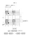
図1は、本発明のディジタル信号記録方法についての第1の実施例を示す図であって、ビットシフトによる1セクタ内の誤ったフレーム位置の識別を回避するディジタル信号記録方法の一例を示してある。図1において参照数時1は1セクタ内に含まれる26フレームの中でセクタIDを含む同期フレームにのみ1回だけ与えられ、セクタの先頭フレームであることを示す先頭同期信号、2はディスク上のセクタ単位での記録位置を示し少なくともセクタID番号を含むセクタID、3は1セクタを構成する26フレームそれぞれの先頭に付加される同期信号の構成要素のうち、前フレーム最終のコードワード、つまりランレングスリミテッドコードに対する最大ラン長、最小ラン長の制約を満たすビットパターンとなるように付加される接続ビットと、接続ビットと共に最大ラン長、最小ラン長の制約を満たしながら同期信号の種別を示すビットパターンが割り当てられる識別ビットから構成される接続、識別ビット、4は全ての同期信号に共通のビットパターンが与えられ各フレームの先頭を示す共通同期パターン、5は1セクタ内に含まれる26フレームそれぞれのセクタ内での位置を示したフレーム位置、6は26フレームで構成されるディスク上の記録単位の一つであるセクタを示す。
【0018】
図1においては1セクタに含まれる26フレームそれぞれの先頭に付加される同期信号はSY0〜SY7であり、それぞれの同期信号の各フレームに対する配置を示している。更にその前後のセクタにおけるフレーム配置の一部を示すことでセクタ間のフレーム同期信号の配置関係を示している。図1におけるフレーム分割は、例えば図2(b)に示したインタリーブ配列における1行の行データにつき2フレームとなっており、同期信号SY0〜SY7の配置は、セクタID2を含むフレームに先頭同期信号SY0を与え、左側のフレームについてはSY1〜SY4を周期的に繰り返して配置、右側のフレームについては同期信号SY5を5フレーム、同期信号SY6、SY7についてはそれぞれ4フレーム連続するように配置する。このような同期信号SY0〜SY7を配置した結果、1セクタ内でSY5領域、SY6領域、SY7領域の3領域に分割されることになり、SY5、SY6、SY7の各同期信号の識別によって領域が特定される。更に各領域内において同期信号SY0、SY1〜4の識別によってフレーム位置を特定することになる。今、少なくともSY5、SY6、SY7の同期信号に含まれる接続、識別ビット3と共通同期パターン4に含まれるビットパターンの反転ビット数が同じであると仮定する。この場合ビットシフトによる同期信号の誤った識別によるフレーム位置の誤った特定が原因で発生するバースト的なエラーフレームの伝播を防ぐ目的で、少なくとも同期信号SY5、SY6、SY7に与えられる全てのビットパターンに対し、SY5とSY6、SY5とSY7、SY6とSY7それぞれのビットパターン間での符号間距離を2以上とし、ビットパターン同士の相似度を低くする。この場合1セクタ内で分割された3つの領域においてSY5、SY6、 SY7の各同期信号に1ビットシフトが発生した場合でも互いに符号間距離が2のため少なくともSY5、SY6、SY7それぞれの領域間では互いに誤った同期信号の識別は行われないことになる。つまり1セクタ内でのフレーム位置の特定を例えば連続する数フレームで行うことでSY5、SY6、SY7の各領域内では別の領域に対するフレーム位置の特定が行われなくなり、セクタ内でのエラーフレーム伝播を防止することができる。更にはSY5、SY6の領域内で、SY7領域において行われる次セクタの先頭フレームの予想が行われないことになりセクタを超えたエラーフレームの伝播を防止することができる。またビットシフトによりSY0〜SY4と識別された場合や、識別されない場合であっても、1セクタ内でのフレーム位置の特定を例えば連続する3フレームで行うことでフレーム位置の特定は前特定位置からの予測値となり、再生フレームとフレーム位置の特定結果が一致し、バーストエラー的なエラーフレームが発生しないことになる。また反転ビット数が互いに異なるSY5、SY6、SY7をそれぞれ与え、ビットパターン同士の相似度を低くした場合にでもエラーフレームの発生を防止することが可能である。例えばSY5、6、7の間で反転ビット数を(SY7)>(SY6)>(SY5)の関係にしたビットパターンを与えることが考えられる。
【0019】
以上説明した第1の実施例において、1セクタ内のフレーム位置特定を更に正確に行うため、同期信号{SY5、SY6、SY7}と同期信号SY0、SY1、SY2、SY3、SY4それぞれのビットパターンに与える互いの符号間距離、反転ビット数の関係について説明する。
【0020】
1セクタ内の領域を分割する{SY5、SY6、SY7}とSY0或いは{SY1、SY2、SY3、SY4}それぞれの間で同期信号ビットパターンの相似度を低くするため、それらの間で符号間距離が互いに2以上のビットパターン、或いは反転ビット数の異なるビットパターンを与える。例えば{SY5、SY6、SY7}とSY0、{SY5、SY6、SY7}と{SY1、SY2、SY3、SY4}の間、更にはSY0と{SY1、SY2、SY3、SY4}の間それぞれの組み合わせにおいて互いに符号間距離2以上となるビットパターンを与える。
【0021】
反転ビット数が異なる場合には、例えばSY0>{SY5、SY6、SY7}>{SY1、SY2、SY3、SY4}の関係となるようなビットパターンを与える。
【0022】
更に符号間距離2以上のビットパターンと、反転ビット数の異なるビットパターンを組み合わせることで同期信号に割り当て可能なビット数の増加を押さえ、ビットパターン同士の相似度についても低くすることが可能である。例えば反転ビット数の関係がSY0>{SY5、SY6、SY7}>{SY1、SY2、SY3、SY4}となるように与え、かつ{SY5、SY6、SY7}と{SY1、SY2、SY3、SY4}それぞれの組み合わせにおいては反転ビット数が同一で、互いの符号間距離が互いに2以上となるようなビットパターンを与える。或いは例えば、SY0と{SY5、SY6、SY7}と{SY1、SY2、SY3、SY4}それぞれの組み合わせの間で互いに符号間距離を2以上とし、かつ反転ビット数については{SY5、SY6、SY7}において例えばSY7>SY6>SY5の関係、{SY1、SY2、SY3、SY4}において例えばSY1>SY2>SY3>SY4の関係となるビットパターンを与える。この場合{SY5、SY6、SY7}、{SY1、SY2、SY3、SY4}の組み合わせの間で反転ビット数が同一であるビットパターンがあってもよい。例えば反転ビット数がSY7とSY1、SY6とSY2、SY5とSY3が同一であってもかまわない。しかしながら符号間距離はそれらの組み合わせの中で互いに2以上のビットパターンが与えられており、ビットパターン同士の相似度は低いことになる。
【0023】
反転ビット数の関係を例えばSY0>SY7>SY6>SY5>{SY1、SY2、SY3、SY4}の関係とし、{SY1、SY2、SY3、SY4}の組み合わせにおいては反転ビット数が同一で、互いの符号間距離が互いに2以上となるようなビットパターンを与える場合や、反転ビット数の関係を例えばSY0>SY1>SY2>SY3>SY4>{SY5、SY6、SY7}の関係とし、{SY5、SY6、SY7}の組み合わせにおいては反転ビット数が同一で、互いの符号間距離が互いに2以上となるようなビットパターンを与える場合もある。
【0024】
SY0については、その他の同期信号に対するビットパターンとの相似度が最も低いことが望ましいが、他の同期信号との反転ビット数が同一、或いは符号間距離1であってもかまわない。例えば反転ビット数がSY0と{SY5、SY6、SY7}の間で同一とし、符号間距離を互いに2以上とする場合もある。
【0025】
一方で{SY1、SY2、SY3、SY4}の組み合わせにおける全てのビットパターンが互いに符号間距離が2以上、或いは反転ビット数が異なることに限定されず、互いの符号間距離2以上のビットパターンと反転ビット数が異なるビットパターンの組み合わせによって同期信号に割り当て可能なビット数の増加を押さえながら{SY1、SY2、SY3、SY4}における互いのビットパターンの相似度を低くすることも考えられる。例えば反転ビット数の関係を{SY1、SY2}>{SY3、SY4}として与え、{SY1、SY2}、{SY3、SY4}それぞれの組み合わせにおいては反転ビット数が同一であり、互いの符号間距離が2以上となるビットパターンを与える場合もある。
【0026】
また{SY5、SY6、SY7}の組み合わせにおける全てのビットパターンについても、互いに符号間距離2以上、或いは反転ビット数が異なるビットパターンに限定されずに、互いの符号間距離が2以上のビットパターンと、反転ビット数が異なるビットパターンの組み合わせによって同期信号に割り当て可能なビット数の増加を押さえながら{SY5、SY6、SY7}における互いのビットパターンの相似度を低くすることも考えられる。例えば反転ビット数をSY7>{SY5、SY6}の関係になるようにし、SY5とSY6については反転ビット数は同一で、互いの符号間距離が2以上となるビットパターンを与える場合もある。
【0027】
図5は本発明の第2の実施例を示す図であり、少なくともSY5、SY6、SY7の同期信号に含まれる接続、識別ビット3と共通同期パターン4に含まれる反転ビット数が同じであると仮定し、ビットシフトによる同期信号の誤った識別が発生した場合のバースト的なエラーフレームの伝播を防ぐ目的で、少なくともSY5、SY6、SY7に与えられる全てのビットパターンに対し、SY5、SY6については符号間距離が1のままで、SY7についてはSY5、SY6それぞれの間で符号間距離を2以上としたビットパターンを与え、SY7とSY5、SY7とSY6との間でビットパターンの相似度を低くした場合を示してある。
【0028】
この場合1セクタ内で分割された3つの領域におけるSY5、SY6、SY7の同期信号に1ビットシフトが発生した場合でも符号間距離が2であるため少なくともSY7の領域内で誤った同期信号SY5、SY6の識別は行われず、またSY5、SY6の領域内でも誤った同期信号SY7の識別は行われないことになる。つまり1セクタ内でのフレーム位置の特定を例えば連続する数フレームで行うことでSY5、SY6の領域内ではSY7領域において行われる次セクタの先頭フレームの予想が確実に行われないことになり、少なくともセクタを超えたエラーフレームの伝播を防止することができる。また反転ピット数がSY0が最大で、反転ビット数が(SY5、SY6)とSY7との間で異なるビットパターンを与えることで相似度を低くした場合にでも上記したセクタを超えたエラーフレームの伝播を少なくとも防止することが可能である。例えばSY5、6、7の間で反転ビット数を(SY7)>(SY6、SY5)の関係にしたビットパターンを与えることが考えられる。或いは符号間距離と反転ビット数の組み合せで例えばSY7と(SY6、SY5)の間で符号間距離が2となるビットパターンを割当て、異なる反転ビット数をSY6、SY5のビットパターンに対し与える、或いはその逆で 異なる反転ビット数のY7と(SY6、SY5)のビットパターンを与え、SY5、SY6の間で符号間距離2のビットパターンを与えることも有りうる。
【0029】
以上説明した第2の実施例についても1セクタ内のフレーム位置特定を更に正確に行うため、第1の実施例において説明した{SY5、SY6、SY7}、SY0、{SY1、SY2、SY3、SY4}における同期信号の組み合わせそれぞれに対し、符号間距離2以上、反転ビット数の異なるビットパターンが同様に与えられる。
【0030】
図6は本発明の第3の実施例を示す図であって、セクタ先頭を示す先頭同期信号SY0のフレームから次セクタの先頭フレーム手前のフレームを、少なくともmフレーム(mは正の整数)とnフレーム(nは正の整数)に領域分割し、互いに相似度の低いビットパターンの同期信号を配置する方法を示している。図6において例えばSY(m+n)の(n+m)は1セクタ内でのフレーム位置を示しており、1セクタは合計(n+m)フレームで構成される。この(n+m)フレームにおいてセクタIDを含む次セクタの先頭フレーム手前のnフレームにおいて、それらnフレームに含まれる同期信号SY(m+1)〜SY(m+n)に与えられる全てのビットパターンに対し互いに符号間距離を2以上とすることで相似度を互いに低くする。この場合例えばフレーム位置の判定連続フレーム数をkフレーム(kは正の整数でk≦n)とすると、セクタ最終のnフレームにおいて1ビットシフトが発生した場合にでも互いに符号間距離が2であるためフレーム位置の識別は正しく行われ、次セクタにまたがるエラーフレームの伝播を防止することができる。特にフレーム位置の判定フレーム数をk<nとすることで少なくともnフレームの領域内でのフレーム位置の判定を数回行うことが可能となり、フレーム位置の識別を確実に行うことが可能となる。また反転ピット数がSY(0)が最大で、nフレームに含まれる同期信号全ての反転ビット数が異なるSY(m+1)〜SY(m+n)を与えた場合にでも上記した次セクタにまたがるエラーフレームの伝播を防止することが可能である。例えばSY(m+1)〜SY(m+n)の間で反転ビット数をSY(m+n)>SY(m+n−1)>・・・>SY(m+2)>SY(m+1)の関係にしたビットパターンを与えることが考えられる。
【0031】
以上説明した第3の実施例においても、1セクタ内のフレーム位置特定を更に正確に行うため、セクタIDを含むフレーム手前のnフレームとその他のmフレームに対する同期信号のビットパターンに与える符号間距離、反転ビット数の関係について説明する。
【0032】
1セクタ内の領域を分割するnフレームに含まれる同期信号の組み合わせと、mフレームに含まれる同期信号の組み合わせの間においてもビットパターンの相似度を低くするため、それらの間で符号間距離が互いに2以上のビットパターン、或いは反転ビット数の異なるビットパターンを与えることが考えられる。例えばnフレームに含まれる全ての同期信号の組み合わせとmフレームに含まれる全ての同期信号の組み合わせの間で互いに符号間距離2以上となるビットパターンを与える。反転ビット数が異なる場合には、例えば{nフレームに含まれる全ての同期信号の組み合わせ}>{mフレームに含まれる同期信号の組み合わせ}の関係となるようなビットパターンを与える。
【0033】
また同期信号に割り当てられるビット数の制限から符号間距離2以上のビットパターンと反転ビット数が異なるビットパターンの組み合わせで互いのビットパターンの相似度を低くする場合もある。例えば反転ビット数の関係を{nフレームに含まれる同期信号の組み合わせ}>{mフレームに含まれる同期信の組み合わせ号}として与え、かつnフレームに含まれる同期信号の組み合わせ、mフレームに含まれる同期信号の組み合わせそれぞれにおいては反転ビット数が同一で、互いの符号間距離が互いに2以上となるようなビットパターンを与える。或いは{nフレームに含まれる同期信号の組み合わせ}、{mフレームに含まれる同期信号の組み合わせ}それぞれにおいては反転ビット数がそれぞれ異なるビットパターンを与え、かつ{nフレームに含まれる同期信号の組み合わせ}と{mフレームに含まれる同期信号の組み合わせ}の間では互いに符号間距離2以上となるビットパターンを与える場合もある。この場合も、nフレームに含まれる同期信号の組み合わせと、mフレームに含まれる同期信号の組み合わせの一部で反転ビット数が同一のビットパターンが存在するが、それら互いの符号間距離は2以上であり、ビットパターンの相似度は低いことになる。
【0034】
またnフレームに含まれる同期信号のビットパターンについては反転ビット数がすべて異なるビットパターンを与え、mフレームに含まれる同期信号のビットパターンについては反転ビット数はすべて同一であり、互いの符号間距離が2以上となるビットパターン、或いはその逆でnフレームに対しては互いの符号間距離2以上、mフレームに対しては反転ビット数の異なるビットパターンを与えることでnフレーム、mフレームに含まれる同期信号のビットパターンの相似度を低くすることも考えられる。この場合もたとえばnフレームに含まれる同期信号の反転ビット数と、mフレームに含まれる反転ビット数が同一のものが存在する場合もあるが、それら互いに符号間距離は2以上となっておりビットパターン同士の相似度は低いことになる。
【0035】
一方でmフレームに含まれる同期信号における全てのビットパターンについては互いに符号間距離が2以上、或いは反転ビット数が異なることに限定されず、互いの符号間距離2以上のビットパターンと反転ビット数が異なるビットパターンの組み合わせによってmフレームに含まれる全ての同期信号に対する互いの相似度を低くすることも考えられる。例えばmフレーム中、1フレーム以上のフレームごとに第1の分割領域から第k(kは正の整数)の分割領域に細分し、それら分割領域に対する同期信号の反転ビット数を{第1の分割領域}>{第2の分割領域}>・・・>{第kの分割領域}の関係として与え、かつ各第1から第kのそれぞれの分割領域に含まれる同期信号のビットパターンはそれぞれの組み合わせにおいては反転ビット数が同一であり、互いの符号間距離が2以上となるビットパターンを与える、或いは{第1の分割領域}、{第2の分割領域}、・・・{第kの分割領域}それぞれの組み合わせに含まれる同期信号に対し異なる反転ビット数を与え、かつ{第1の分割領域}、{第2の分割領域}、・・・{第kの分割領域}の各組み合わせの間で互いに符号間距離が2以上となるビットパターンを与えることが考えられる。
【0036】
またnフレームに含まれる同期信号におけるビットパターンにつても、互いに符号間距離2以上、或いは反転ビット数が異なるビットパターンに限定されずに、符号間距離が2以上のビットパターンと、反転ビット数が異なるビットパターンの組み合わせによって互いのビットパターンの相似度を低くすることも考えられる。例えばnフレーム中、1フレーム以上のフレームごとに第1の分割領域から第h(hは正の整数)の分割領域に細分し、それら分割領域に対する同期信号の反転ビット数を{第1の分割領域}>{第2の分割領域}>・・・>{第hの分割領域}の関係として与え、かつ各第1から第hのそれぞれの分割領域に含まれる同期信号のビットパターンはそれぞれの組み合わせにおいては反転ビット数が同一であり、互いの符号間距離が2以上となるビットパターンを与える、或いは{第1の分割領域}、{第2の分割領域}、・・・{第hの分割領域}それぞれの組み合わせに含まれる同期信号に対し異なる反転ビット数を与え、かつ{第1の分割領域}、{第2の分割領域}、・・・{第hの分割領域}の各組み合わせの間で互いに符号間距離が2以上となるビットパターンを与えることが考えられる。
【0037】
図7は本発明の第4の実施例を示す図であって、セクタ先頭を示す先頭同期信号SY0のフレームから次セクタの先頭フレーム手前のフレームを、少なくともmフレーム(mは正の整数)とnフレーム(nは正の整数)に領域分割し、互いに相似度の低いビットパターンの同期信号を配置する別の方法を示している。図7においても例えばSY(m+n)の(n+m)は1セクタ内でのフレーム位置を示しており、1セクタは合計(n+m)フレームで構成される。この(n+m)フレームにおいてセクタIDを含む次セクタの先頭フレーム手前のnフレームにおいて、それらnフレームに含まれる同期信号SY(m+1)〜SY(m+n)に対し、例えば1フレームおきの同期信号に与えられる全てのビットパターンに対し互いに符号間距離を2以上とすることで相似度を互いに低くしたビットパターンを与える。この場合も例えばフレーム位置の判定フレーム数をkフレーム(kは正の整数でk≦n)とすると、セクタ最終のnフレームにおいて1ビットシフトが発生した場合にでも、1フレームおきに互いに符号間距離が2であるためフレーム位置の識別は正しく行われ、次セクタにまたがるエラーフレームの伝播を防止することができる。特にフレーム位置の判定フレーム数をk<nとすることでnフレームの領域内でのフレーム位置の判定を数回行うことが可能で、少なくともnフレームの領域内でフレーム位置の識別を確実に行うことが可能となる。また反転ピット数がSY(0)が最大で、nフレームに含まれる同期信号に対して例えば1フレームおきに反転ビット数が異なるSY(m+2)、SY(m+4)、・・・SY(m+n)を与えた場合にでも上記した次セクタにまたがるエラーフレームの伝播を防止することが可能である。例えば反転ビット数をSY(m+n)>SY(m+n−1)>・・・>SY(m+4)>SY(m+2)の関係にしたビットパターンを与えることが考えられる。この第4の実施例でnフレームにおける符号間距離2のビットパターン、或いは異なる反転ビット数のビットパターンを与える際には、上記した例にとらわれず、2、3、4、・・・フレームおきとしても構わなく、数フレームおきに与えられる符号間距離2のビットパターン、或いは異なる反転ビット数のビットパターンは2、3、4・・・フレーム連続して与えても構わない。
【0038】
以上説明した第4の実施例においても、1セクタ内のフレーム位置特定を更に正確に行うため、セクタIDを含むフレーム手前のnフレームとその他のmフレームに対する同期信号のビットパターンそれぞれに与える符号間距離、反転ビット数の関係についても、第3の実施例において説明した場合と同様の方法が適用される。
【0039】
またnフレームに含まれる同期信号に対するビットパターンについては、1フレーム以上のフレームごとに互いに符号間距離2以上、或いは反転ビット数が異なるビットパターン、それらの組み合わせにより互いに相似度の低いビットパターンが与えられることに限定されず、nフレームに含まれる全ての同期信号についても、互いの符号間距離、反転ビット数の組み合わせで同期信号に対するビットパターンの相似度を低くする場合もある。例えばnフレーム中、1フレーム以上のフレームごとに符号間距離2以上、或いは反転ビット数の異なるビットパターンを与える同期信号とそれ以外のフレームについて、反転ビット数の関係を(nフレームに含まれる符号間距離2以上の同期信号)>(nフレームに含まれるその他の同期信号)として与える。更にnフレームに含まれるその他の同期信号についても互いの符号間距離が2以上となるビットパターンを与えることで全ての同期信号の互いのビットパターンの相似度を低くすることが考えられる。
【0040】
図8は本発明の第5の実施例を示す図であって、セクタ先頭を示す先頭同期信号に対するフレームから次のセクタ先頭フレーム前のフレームに対し例えばpフレーム(pは正の整数)、qフレーム(qは正の整数)、rフレーム(rは正の整数)の3つの領域に分割する際に、各領域の最終フレームを含む例えば2フレームに対し符号間距離が2、或いは反転ビット数の異なる相似度の互いに低い同期信号を配置する方法を示してある。図8において例えばSY(p)の(p)は1セクタ内に含まれるフレーム位置を示しており、1セクタは合計(p+q+r)フレームで構成される。この(p+q+r)フレームにおいて例えば第1の領域の最終2フレームSY(p−1)とSY(p)、同様に第2の領域のSY(q−1)、SY(q)、第3の領域のSY(r−1)、SY(r)のフレームに対し、各領域の最終2フレームが互いに符号間距離が2となるようにビットパターンを与え、最終2フレームの間でビットパターンの相似度を低くする。例えばSY(p−1)とSY(p)の間の符号間距離は2であり、SY(q)とSY(q−1)、SY(r)とSY(r−1)それぞれの組み合わせに対するビットパターンに対する符号間距離も2となる。更に第1の領域におけるSY(p−1)とSY(p)、第2の領域におけるSY(q)とSY(q−1)、第3の領域におけるSY(r)とSY(r−1)との間で反転ビット数を{SY(p−1)、SY(p)}>{SY(q)、SY(q−1)}>{SY(r)、SY(r−1)}となるように与え、各領域を示す最終2フレームの間でビットパターンの相似度を低くする。或いは領域ごとの最終2フレームの相似度を反転ビット数が異なることにより低くし、各領域同士の最終2フレーム同士で符号間距離を2とする場合もある。このような符号間距離、反転ビット数を図8に示すように配置することによりエラーフレームの伝播は各領域内に留まり、更には次セクタにまたがるエラーフレームの伝播を防止することができる。また各領域の最終フレーム数は2フレームに限らず、1フレーム或いは3、4、・・・フレームであっても良く、p、q、rフレームごとに分割される領域については3つの領域に限定されず、2領域、或いは4、5、・・・領域としても良い。
【0041】
以上説明した第5の実施例においても、1セクタ内のフレーム位置特定を更に正確に行うため、各領域を分割する最終数フレームに対する同期信号のビットパターンに与える符号間距離、反転ビット数の関係、更には各領域ごとの最終数フレームとそれ以外のフレームに対する同期信号のビットパターンそれぞれに与える符号間距離、反転ビット数の関係それぞれについて説明する。
【0042】
各領域を分割する最終数フレームについては、各最終数フレームに含まれる同期信号の符号間距離が互いに2以上を与え、かつ各領域の最終数フレーム同士に互いに異なる反転ビット数のビットパターンを与える、或いは各最終数フレームに含まれる同期信号に異なる反転ビット数のビットパターンを与え、かつ各領域の最終数フレーム同士が互いに符号間距離2のビットパターンを与える限定されずに、各領域を分割する全ての最終数フレームについてもすべて互いの符号間距離が2以上、或いは反転ビット数が全て異なる同期信号のビットパターンが与えられる場合もある。
【0043】
また、各分割領域において最終数フレームとそれ以外のその他のフレームに対する同期信号についても、符号間距離と反転ビット数の組み合わせにより同期信号に対する相似度を低くする場合がある。例えば反転ビット数を{最終数フレームに含まれる同期信号}>{その他フレームに含まれる同期信号}となるように与え、かつ{最終数フレームに含まれる同期信号}、{その他フレームに含まれる同期信号}それぞれにおいて符号間距離が互いに2以上となるビットパターンを与える場合や、{最終数フレームに含まれる同期信号}、{その他フレームに含まれる同期信号}それぞれにおいて異なる反転ビット数となるビットパターンを与え、かつ{最終数フレームに含まれる同期信号}と{その他フレームに含まれる同期信号}の間では符号間距離が互いに2以上となるビットパターンを与える場合がある。
【0044】
また、各領域同士の間で符号間距離2以上のビットパターン、互いに反転ビット数の異なるビットパターン、それらを組み合わせることにより互いの同期信号の相似度を低くしたビットパターンを与え、相似度を低くする場合もある。
【0045】
また、各領域において、領域分割する最終数フレーム以外のその他のフレーム同士すべての間で互いに符号間距離2以上のビットパターン、互いに反転ビット数の異なるビットパターン、それらを組み合わせることにより互いの同期信号の相似度を低くしたビットパターンを与え、相似度を低くする場合もある。
【0046】
なお本発明における同期信号には共通の同期パターンを用い、接続ビットと識別ビットによって同期信号の種類の判定を行っているがこれに限定されず、同期信号に含まれるビットパターンに対し符号間距離2あるいは反転ビット数の異なれば共通同期パターンを用いなくても良い。例えば第2の実施例においてセクタの最終領域を示すSY7、セクタ先頭を示すSY0に含まれる同期パターンを他のSY1〜SY6までに共通の同期パターンとは別パターンとし、接続ビット、識別ビットによりSY7、SY0を判定しても構わない。
【0047】
また本発明のディジタル信号生成方法における同期フレームはディスク状の記録媒体に記録され、セクタIDの検出によってセクタ単位でのアクセス、再生を可能とするものであり。更に同期フレーム記録の対象となるディスク状の記録媒体は記録情報の先頭から終わりまでに対する同期フレームを全て連続してトラック上書き込むものに限定されず、書換え可能なディスク上のプリピットとしてディスク中の物理アドレスが刻まれ、そのプリピットの間にセクタ単位で1セクタに対するフレームを連続的に書き込み、セクタ間は非連続的となる場合の光ディスクにも適応できる。
【0048】
また第3、第4、第5の実施例において1セクタ内を構成する同期フレームは第1、第2の実施例で示したSY0〜SY7の配置が対応する場合も有りうる。第3、第4、第5の実施例では符号間距離が互いに2、或いは反転ビット数が互いに異なるビットパターンの位置だけを示しており、例えば第3の実施例においてSY0〜SY7の同期信号の配置を適応した場合にでも同じSY7の同期信号であってもその符号間距離は互いに2であり、反転ビット数も互いに異なるビットパターンが当てはまることになる。
【0049】
また第1〜第5の実施例において説明した同期信号の互いのビットパターンの符号間距離は2に限定されず、全てが2以上、あるいは例えばあるビットパターンに対しては符号間距離が2で別のビットパターンに対しては符号間距離3であるような符号間距離の異なる組み合わせでも構わない。
【0050】
また第1〜第5の実施例で説明した符号間距離2、或いは反転ビット数の異なるビットパターンを持つ同期信号については、同期信号に割り当てられるビット数の制限があっても各実施例において必要なビットパターンの種類を満たす目的で、互いに符号間距離が2以上のビットパターンと互いに反転ビット数の異なるビットパターンを組み合せることにより、互いのビットパターン同士の相似度を低くしても構わない。
【0051】
【発明の効果】
以上説明したように本発明によると、1セクタを複数の同期フレームに分割してディスク記録媒体に記録する際に、複数フレームにおける同期信号に対し符号間距離が互いに2、或いは反転ビット数の異なるビットパターンの配置を行うことで、ビットシフトによるフレーム同期信号の誤った識別を回避し、1セクタ内におけるフレーム位置の誤った判定によるバースト的なエラーフレームの伝播を防止することができる。エラーフレームの伝播を少なくとも1セクタ内に収めることが可能となり再生不能を防止することが可能である。
【図面の簡単な説明】
【図1】本発明によるディジタル信号記録方法の第1の実施例を示す図。
【図2】ディスクに記録するディジタル信号の生成方法の一例を示す図。
【図3】同期信号の構成要素とビットパターンを示す図。
【図4】同期信号に対する反転ビット数と符号間距離が1の同期信号の対応を示す図。
【図5】本発明によるディジタル信号記録方法の第2の実施例を示す図。
【図6】本発明によるディジタル信号記録方法の第3の実施例を示す図。
【図7】本発明によるディジタル信号記録方法の第4の実施例を示す図。
【図8】本発明によるディジタル信号記録方法の第5の実施例を示す図。
【符号の説明】
1…先頭同期信号、2…セクタID、3…接続、識別ビット、4…共通同期パターン、5…フレーム位置、6…セクタ。[0001]
BACKGROUND OF THE INVENTION
The present invention relates to a digital signal recording method and an information recording medium, and more particularly, to a recording pit (mark) on a disk recording medium for a digital signal corresponding to a synchronization frame generated by modulating a recording information and adding a synchronization signal. ) As a digital signal recording method and information recording medium.
[0002]
[Prior art]
A synchronization frame is formed by adding a synchronization signal indicating the head in a fixed amount of data unit after modulation processing is performed on the recorded information, and the digital signal corresponding to the synchronization frame is recorded on a recording pit (mark As an example of a disc recording medium to be recorded as (), there is a DVD (Digital Versatile Disc). The digital signal generation method for this DVD is described in the publicly known examples of “NIKKEI ELECTRONICS BOOKS Data Compression and Digital Modulation 1998 Edition pp. 121-123” and “JP-A-9-162857 Digital Data Transmission Method”. Has been. This technique will be described with reference to FIGS. 2, an array in which information unique to a sector such as a sector ID number indicating a recording address on the disk is added to recording information of 2 kilobytes (2048) stored in a sector which is a recording unit on the disk, 172 Sector data is composed of bytes × 12 rows, and then, for an array of 172 bytes × 12 rows × 16 sectors = 32 kilobytes in which 16 pieces of sector data are collected, a PO correction code of 16 bytes for a vertical sequence, a horizontal sequence A correction block is configured by adding a PI correction code of 10 bytes, and for a row data including a PO correction code, an interleaved array is configured by distributing one row for every 12 rows of sector data. Further, by performing 8-16 modulation processing and adding a synchronization signal to the row data included in the interleaved array, two synchronization frames are generated per row. Regarding the arrangement method of the eight kinds of synchronization signals SY0 to SY7 for the generated synchronization frame, one synchronization signal of SY0 is included in the first synchronization frame from the first synchronization frame including the sector ID number to 26 synchronization frames for the PO correction code. Are arranged and arranged in the order of SY5, SY1, SY5,. Further, digital signals for the synchronization frames are continuously recorded on the disc in accordance with the arrangement order of the synchronization signals, SY0, SY5, SY1, SY5,. For the 8-16 modulation process, an RLL (Run Length Limited) encoding method is used. When T is a unit of recording bit (mark) interval on the disk, the minimum run length d = 2T and the maximum run length k = The 8-bit data included in the row data is converted into a 16-bit (1 word) code word so as to satisfy the 10T run length limit. The number of synchronization frames for row data is composed of two frames for the purpose of easily performing synchronization pull-in in units of synchronization frames and preventing error propagation due to loss of synchronization. As for the arrangement of the synchronization signals SY0 to SY7 for the 26 synchronization frames, SY0 is given only once for the first synchronization frame including the sector ID number so that the frame position within one sector can be specified. SY1 to SY4 are arranged in a periodic manner for the left synchronization frame, and each of SY5, SY6, and SY7 is divided into three areas so that one sector is divided into three areas in the right synchronization frame. It is added continuously. FIG. 3 shows the configuration of the synchronizing signals SY0 to SY7 shown in the above-mentioned known example and the bit pattern to be given. The synchronization signal is composed of 32 bits, and three types of connection bits {000} {001} {100 for keeping the restrictions on the minimum run length and the maximum run length between the last code word included in the synchronization frame and the synchronization signal. } And the identification pattern of the synchronization signals SY0 to SY7, the bit pattern of 4T or more and -14T-4T including the bit pattern deviating from the restriction of the maximum run length, and the synchronization pattern common to all the synchronization signals SY0 to SY7 Composed.
[0003]
A total of 32 types of synchronization signals are constituted by the types of connection bits, and are classified into (a-1), (a-2), (b-1), and (b-2) in FIG. Addition of each classified sync signal is performed by selecting an optimum bit pattern that satisfies the minimum run length and maximum run length constraints according to the immediately preceding code word and that minimizes the DC component in the digital signal for the sync frame. . For example, even if the synchronization signal SY0 is a bit pattern indicating the same synchronization signal SY0 depending on the connection bit and the identification pattern, the connection bit pattern is different for the purpose of satisfying the restrictions on the minimum run length and the maximum run length with respect to the immediately preceding code word ( a-1), (a-2), (b-1), and (b-2). Furthermore, even for the same connection bit for the purpose of suppressing the DC component, the identification pattern is different (a-1). ) And (a-2) or (b-1) and (b-2) in total. At the time of frame reproduction, data synchronization is performed in units of frames by detecting the synchronization signal, and the frame position within one sector is detected from the continuous detection result of the synchronization signals SY0 to SY7, and the detection result and the sector ID number are detected. The original recorded information is reproduced by restoring the original interleaved array from the result and performing error correction processing by decoding the correction code.
[0004]
[Problems to be solved by the invention]
FIG. 4 shows the case where the similarity between the bit patterns of the synchronization signal in the above-described prior art is shown using the number of inverted bits and the inter-code distance. Here, the number of inverted bits means that the recording mark (pit) formed on the disk is inverted and NRZI (Non Return to Zero Inverted) recording is performed only when the data bit included in the synchronization frame is 1. The number of appearances of the data bit “1” included in the bit pattern of the synchronization signal is counted, and the similarity of the bit pattern decreases as the number of inversions increases with respect to other synchronization signals. Regarding the inter-code distance, the number of inverted bits with respect to the bit pattern of the synchronization signal is the same, and the number of shifts required to shift the position of the data bit “1” to coincide with the bit pattern for another synchronization signal is given as the inter-code distance. . FIG. 4 shows the synchronization signal with the inter-code distance = 1 for the number of inverted bits and the synchronization signals SY0 to SY7 for each classification of the synchronization signal. In each of the classifications (a-1), (a-2), (b-1), and (b-2), in particular, a synchronization signal having a code-to-code distance of 1 is shifted by 1 bit as another synchronization signal. Likely to be identified. On the other hand, at the time of disc reproduction, slice level adjustment is performed when the reproduction signal is binarized (digitized). In an unstable state in which the slice level adjustment fluctuates, or in a state where inter-code interference occurs in adjacent recording marks (pits), the bit that is shifted by 1 bit before and after the original bit position is binarized. Shift easily occurs. Therefore, in consideration of bit shift, the synchronization pattern constituting the synchronization signal is 3T outside the maximum interval 11T due to the maximum run length constraint after 8-16 modulation, and 1T greater than the minimum interval 3T due to the minimum run length constraint 4T A common synchronization pattern is given to all the synchronization signals of -14T-4T. However, with respect to the connection bits and identification patterns in the synchronization signal, as shown in FIG. 4, there is a synchronization signal with an intersymbol distance of 1, so that the synchronization signals SY0 to SY7 are erroneously identified by bit shift. For write-once discs and rewritable discs in particular, they may be slightly longer or shorter than the original mark length due to physical disturbances such as vibration when recording marks are formed on the disc, and uneven recording mark formation. Yes, in order to increase the storage capacity of the disc, if the track pitch on the recording medium and the recording mark (pit) length are made finer and high density recording is performed, the disturbance during the above mark formation and the formation unevenness of the recording mark are affected. Bit shifts are expected to occur frequently due to disturbances during playback. A problem will be described when the erroneous identification of the synchronization signal due to the bit shift occurs in, for example, 26 synchronization frames per sector shown in FIG.
[0005]
In FIG. 2 (c), for example, when specifying the frame position in one sector by identifying the synchronization signal for three consecutive frames, for example, out of 26 frames, the synchronization signal SY5 of the sixth frame is bit-shifted due to bit shift. When the distance is mistakenly identified as SY7, the continuous synchronization signal of SY2-5-3 becomes SY2-7-3 in the seventh frame reproduction, and the correct frame continuity SY3-5 in the subsequent frame reproduction. Two frames between the ninth frames in which -4 is established are erroneously identified as the 23rd to 24th frames in one sector. In this case, although the burst position is not a burst error due to scratches or dust generated on the disk, the frame position specification is incorrect, so a loss occurs in the seventh to eighth frames in one sector, and a burst-like error occurs. Will occur. Further, for example, if SY7 in the 24th and 26th frames is mistakenly identified as SY5 with the intersymbol distance = 1 due to the bit shift, the continuity of the synchronization signal of SY7-4-7 is established in the reproduction of the 26th frame. SY5-4-5 and the erroneous frame position is determined to be the 10th frame. In the subsequent frame reproduction, the correct frame continuity SY0-5-1 is established from the third frame of the next sector, and the frames up to the synchronization frame of the next sector are determined as frames in the current sector. Even if SY0 can be detected correctly in the meantime, the continuity of SY4-7-0 is not established and the frame position at the head of the sector cannot be detected. Therefore, the sector ID number included in the head of the synchronization frame SY0 is not detected, that is, the area to the next sector is not updated in the interleave block shown in FIG.
[0006]
Therefore, the 26 frames of the synchronization frame until the next sector ID number is detected is regarded as a frame in the previous sector without updating the sector, and the 26 frames included between them are updated. Will be lost completely, and the number of burst error frames will be 50 frames in total, 24 frames from the third frame where SY0-5-1 is established and 26 frames where sector loss has occurred. . In this case, since the number of correctable bytes of the PO correction code in the correction block in FIG. 2A is exceeded, correction is impossible, that is, reproduction of the original recorded information is impossible. When playback is not possible, an operation is performed to read again a sector that cannot be corrected again by retry operation. However, if the recorded information is video or audio data, for example, depending on the relationship between the bit rate and the transfer rate to the disc The problem is that the playback video and playback audio are interrupted, and the retry operation cannot be repeatedly executed. In particular, in a high-density disk that generates recording marks at a high density, it is expected that corrections that cannot be corrected due to erroneous identification of the frame position due to the above-described bit shift, that is, reproduction failures, will frequently occur.
[0007]
In the above case, the above problem can be avoided by increasing the number of consecutive frames when performing position determination within one sector to 4 frames and 5 frames. However, when the number of consecutive frames to be determined is, for example, 7 or 8 frames or more, when the synchronization signal of the continuous frame is not detected or the identification of the erroneous synchronization signal by bit shift is performed even in one frame, Naturally, the frame position cannot be determined, and the number of frames required until the next frame continuity is established increases. The same problem occurs when the frame position is specified by detecting only the synchronization signal of SY0 having the maximum number of inverted bits and the maximum intersymbol distance. In this case, there is a discrepancy between the playback frame on the disc and the identification of the frame position when there is a sudden fluctuation in disc rotation, a scratch on the disc, or a burst error due to dust, etc. The number of mismatched frames increases. Accordingly, since the number of burst error frames increases, the number of determination frames cannot be increased.
[0008]
On the other hand, if the inter-code distances between the synchronization signals SY0 to SY7 are all set to 2 or more, or bit patterns having different numbers of inverted bits are given, the problem due to the bit shift is caused.
Although solved, the number of bits allocated to the synchronization signal is limited, and the amount of redundant data not related to the recording information increases, which is not very practical.
[0009]
Accordingly, an object of the present invention is to provide a digital signal recording method and an information recording medium that solve various problems caused by erroneous detection of the frame position.
[0010]
[Means for Solving the Problems]
In order to solve the above problem in the present invention, when the data included in the sector is divided into a plurality of frames including the synchronization signal and recorded on the recording medium, the synchronization signal is a synchronization pattern including at least the identification pattern of the synchronization signal. A method for solving this problem is to provide a bit pattern for a synchronization signal that is configured and that is necessary for specifying a frame position within one sector by detecting an identification pattern included in the synchronization signal of several consecutive frames. The method in the present invention is shown in the following (1) to (5).
[0011]
(1) At least n frames (n is a positive integer) before a synchronization frame including address information indicating a recording position on a recording medium with respect to a sector, a bit pattern given to an n-frame synchronization signal included in the range is The intersymbol distance is 2 or more. Alternatively, bit patterns having different numbers of inverted bits are given. This solution corresponds to the third embodiment.
[0012]
(2) At least n frames (n is a positive integer) before the synchronization frame including address information indicating the recording position on the recording medium with respect to the sector, and k frames (k is a positive integer and k < n) Bit patterns given to every other synchronization signal have an inter-code distance of 2 or more. Alternatively, bit patterns having different numbers of inverted bits are given. This solution corresponds to the fourth embodiment.
[0013]
(3) The same first, second,..., Nth synchronization signal (n is a positive integer) is continued every k frames (k is a positive integer) for at least a plurality of frames included in a sector. When dividing one sector into the first, second,..., Nth areas, the first, second,..., Nth synchronization signals every k frames included in each area. The given bit patterns have a distance between codes of 2 or more. Alternatively, bit patterns having different numbers of inverted bits are given. This solution corresponds to the first embodiment.
[0014]
(4) The same first, second,..., N-th synchronization signal (n is a positive integer) is continued every k frames (k is a positive integer) for at least a plurality of frames included in a sector. When the sector is divided into the first, second,..., Nth areas, the first, second,..., First included in each of the (n−1) areas. The bit pattern given to the (n-1) th synchronization signal and the bit pattern given to the nth synchronization signal included in the nth area including the sector last frame have an inter-code distance of 2 That's it. Alternatively, bit patterns having different numbers of inverted bits are given. This solution corresponds to the second embodiment.
[0015]
(5) The same first, second,..., Nth synchronization signal (n is a positive integer) for each of a plurality of frames included in at least a plurality of frames, and k frames (k is a positive integer). When one sector is divided into first, second,..., Nth areas by arranging them consecutively, the first, second,..., Nth synchronization of consecutive k frames included in each area. The bit patterns given to the signals have an inter-code distance of 2 or more. Alternatively, bit patterns having different numbers of inverted bits are given. This solution corresponds to the fifth embodiment.
[0016]
DETAILED DESCRIPTION OF THE INVENTION
The present invention will be described below with reference to the drawings.
[0017]
FIG. 1 is a diagram showing a first embodiment of a digital signal recording method according to the present invention, showing an example of a digital signal recording method for avoiding erroneous frame position identification within one sector by bit shift. is there. In FIG. 1,
[0018]
In FIG. 1, the synchronization signals added to the head of each of the 26 frames included in one sector are SY0 to SY7, and the arrangement of the respective synchronization signals for each frame is shown. Further, by showing a part of the frame arrangement in the preceding and succeeding sectors, the arrangement relationship of the frame synchronization signals between the sectors is shown. The frame division in FIG. 1 is, for example, 2 frames per row data in the interleaved array shown in FIG. 2B, and the arrangement of the synchronization signals SY0 to SY7 is the first synchronization signal in the frame including the sector ID2. SY0 is given, and SY1 to SY4 are periodically repeated for the left frame, the synchronization signal SY5 for the right frame is arranged for 5 frames, and the synchronization signals SY6 and SY7 are arranged for 4 consecutive frames. As a result of arranging the synchronization signals SY0 to SY7, the sector is divided into three areas of SY5 area, SY6 area, and SY7 area within one sector, and the area is determined by identifying the synchronization signals of SY5, SY6, and SY7. Identified. Further, the frame position is specified by identifying the synchronization signals SY0 and SY1 to SY4 in each region. Assume that at least the connections included in the synchronization signals of SY5, SY6, and SY7 and the number of inverted bits of the bit patterns included in the
[0019]
In the first embodiment described above, in order to more accurately specify the frame position within one sector, the bit pattern of each of the synchronization signals {SY5, SY6, SY7} and the synchronization signals SY0, SY1, SY2, SY3, SY4 The relationship between the given inter-code distance and the number of inverted bits will be described.
[0020]
In order to reduce the similarity of the sync signal bit pattern between {SY5, SY6, SY7} and SY0 or {SY1, SY2, SY3, SY4}, which divide the area in one sector, the inter-code distance between them Give two or more bit patterns or bit patterns having different numbers of inverted bits. For example, in each combination between {SY5, SY6, SY7} and SY0, {SY5, SY6, SY7} and {SY1, SY2, SY3, SY4}, and further between SY0 and {SY1, SY2, SY3, SY4} A bit pattern having a distance between codes of 2 or more is given.
[0021]
When the number of inverted bits is different, for example, a bit pattern having a relationship of SY0> {SY5, SY6, SY7}> {SY1, SY2, SY3, SY4} is given.
[0022]
Furthermore, by combining a bit pattern having an inter-code distance of 2 or more and a bit pattern having a different number of inverted bits, it is possible to suppress an increase in the number of bits that can be assigned to the synchronization signal and to reduce the similarity between the bit patterns. . For example, the relationship between the numbers of inverted bits is SY0> {SY5, SY6, SY7}> {SY1, SY2, SY3, SY4}, and {SY5, SY6, SY7} and {SY1, SY2, SY3, SY4} In each combination, a bit pattern in which the number of inverted bits is the same and the distance between the codes is 2 or more is given. Or, for example, the intersymbol distance between the combinations of SY0 and {SY5, SY6, SY7} and {SY1, SY2, SY3, SY4} is set to 2 or more and the number of inverted bits is {SY5, SY6, SY7}. In SY7>SY6> SY5, for example, {SY1, SY2, SY3, SY4} gives a bit pattern having a relationship of SY1>SY2>SY3> SY4, for example. In this case, there may be a bit pattern in which the number of inverted bits is the same among combinations of {SY5, SY6, SY7}, {SY1, SY2, SY3, SY4}. For example, the number of inverted bits may be the same for SY7 and SY1, SY6 and SY2, and SY5 and SY3. However, as for the inter-code distance, two or more bit patterns are given to each other in the combination, and the similarity between the bit patterns is low.
[0023]
For example, the relationship of the number of inversion bits is SY0>SY7>SY6>SY5> {SY1, SY2, SY3, SY4}. In the combination of {SY1, SY2, SY3, SY4}, the number of inversion bits is the same. When a bit pattern is given such that the inter-code distance is 2 or more, or the relationship of the number of inverted bits is, for example, SY0>SY1>SY2>SY3>SY4> {SY5, SY6, SY7}, and {SY5, SY6 , SY7} may have a bit pattern in which the number of inverted bits is the same and the distance between the codes is 2 or more.
[0024]
As for SY0, it is desirable that the degree of similarity with the bit pattern with respect to other synchronization signals is the lowest, but the number of inverted bits with respect to other synchronization signals may be the same, or the intersymbol distance may be 1. For example, the number of inverted bits may be the same between SY0 and {SY5, SY6, SY7}, and the inter-code distance may be 2 or more.
[0025]
On the other hand, all bit patterns in the combination of {SY1, SY2, SY3, SY4} are not limited to having an inter-code distance of 2 or more or different in the number of inverted bits. It is also conceivable to reduce the degree of similarity of bit patterns in {SY1, SY2, SY3, SY4} while suppressing an increase in the number of bits that can be assigned to the synchronization signal by combining bit patterns having different numbers of inverted bits. For example, the relationship of the number of inverted bits is given as {SY1, SY2}> {SY3, SY4}, and the number of inverted bits is the same in each combination of {SY1, SY2}, {SY3, SY4}, and the inter-code distance In some cases, a bit pattern that gives 2 or more is given.
[0026]
Also, all bit patterns in the combination of {SY5, SY6, SY7} are not limited to bit patterns having a code distance of 2 or more or different in the number of inverted bits, but are bit patterns having a code distance of 2 or more. It is also conceivable to reduce the degree of similarity between the bit patterns in {SY5, SY6, SY7} while suppressing an increase in the number of bits that can be assigned to the synchronization signal by combining bit patterns with different numbers of inverted bits. For example, the number of inverted bits is set to have a relationship of SY7> {SY5, SY6}, and there may be provided a bit pattern in which the number of inverted bits is the same for SY5 and SY6 and the distance between codes is 2 or more.
[0027]
FIG. 5 is a diagram showing a second embodiment of the present invention. At least the connections included in the synchronization signals of SY5, SY6, and SY7, and the number of inversion bits included in the
[0028]
In this case, even if a 1-bit shift occurs in the synchronization signals of SY5, SY6, and SY7 in the three areas divided within one sector, the intersymbol distance is 2, so that an erroneous synchronization signal SY5, at least in the area of SY7, The identification of SY6 is not performed, and the erroneous synchronization signal SY7 is not identified even in the area of SY5 and SY6. In other words, by specifying the frame position in one sector in, for example, several consecutive frames, the prediction of the first frame of the next sector in the SY7 area is not reliably performed in the SY5 and SY6 areas. Propagation of error frames across sectors can be prevented. Propagation of error frames exceeding the above sector even when the number of inversion pits is maximum and SY0 is the maximum by giving different bit patterns between inversion bits (SY5, SY6) and SY7. It is possible to prevent at least. For example, it is conceivable to provide a bit pattern in which the number of inversion bits between SY5, 6, and 7 has a relationship of (SY7)> (SY6, SY5). Alternatively, for example, a bit pattern in which the inter-code distance is 2 between SY7 and (SY6, SY5) is assigned by combining the inter-code distance and the number of inverted bits, and a different inverted bit number is given to the bit pattern of SY6, SY5, or On the other hand, it is possible to give Y7 and (SY6, SY5) bit patterns having different numbers of inverted bits, and to give a bit pattern having a code distance of 2 between SY5 and SY6.
[0029]
Also in the second embodiment described above, in order to more accurately specify the frame position in one sector, {SY5, SY6, SY7}, SY0, {SY1, SY2, SY3, SY4 described in the first embodiment are used. }, A bit pattern having an inter-code distance of 2 or more and a different number of inverted bits is similarly given.
[0030]
FIG. 6 is a diagram showing a third embodiment of the present invention, in which a frame before the first frame of the next sector from the frame of the head synchronization signal SY0 indicating the head of the sector is at least m frames (m is a positive integer). This shows a method of dividing a frame into n frames (n is a positive integer) and arranging synchronization signals having bit patterns with low similarity to each other. In FIG. 6, for example, (n + m) of SY (m + n) indicates a frame position in one sector, and one sector is composed of a total (n + m) frames. In the n frame before the first frame of the next sector including the sector ID in the (n + m) frame, all the bit patterns given to the synchronization signals SY (m + 1) to SY (m + n) included in the n frame are mutually signed. By setting the distance to 2 or more, the similarities are reduced to each other. In this case, for example, if the number of consecutive frames for determining the frame position is k frames (k is a positive integer and k ≦ n), the inter-code distance is 2 even when a 1-bit shift occurs in the last n frames of the sector. Therefore, the frame position is correctly identified, and the propagation of the error frame across the next sector can be prevented. In particular, by setting the number of frames for determining the frame position to be k <n, the frame position can be determined several times within at least the n-frame region, and the frame position can be reliably identified. Further, even when SY (m + 1) to SY (m + n) having different numbers of inversion bits of all the synchronization signals included in the n frame are provided with the maximum number of inversion pits SY (0), the error frame extending over the next sector described above. Can be prevented. For example, a bit pattern in which the number of inverted bits between SY (m + 1) to SY (m + n) is in the relationship of SY (m + n)> SY (m + n-1)>...> SY (m + 2)> SY (m + 1) is given. It is possible.
[0031]
Also in the third embodiment described above, the inter-code distance given to the bit pattern of the synchronization signal for the n frame before the frame including the sector ID and the other m frames in order to more accurately specify the frame position within one sector. The relationship between the number of inverted bits will be described.
[0032]
In order to reduce the similarity of the bit pattern between the combination of the synchronization signals included in the n frames that divide the area in one sector and the combination of the synchronization signals included in the m frames, the intersymbol distance between them is It is conceivable to provide two or more bit patterns or bit patterns having different numbers of inverted bits. For example, a bit pattern having an intersymbol distance of 2 or more is given between a combination of all synchronization signals included in n frames and a combination of all synchronization signals included in m frames. When the number of inverted bits is different, for example, a bit pattern that gives a relationship of {a combination of all synchronization signals included in n frames}> {a combination of synchronization signals included in m frames} is given.
[0033]
In addition, due to the limitation on the number of bits allocated to the synchronization signal, the bit pattern similarity may be lowered by a combination of a bit pattern having an inter-code distance of 2 or more and a bit pattern having a different number of inverted bits. For example, the relationship of the number of inverted bits is given as {combination of synchronization signals included in n frame}> {combination number of synchronization signals included in m frame}, and combination of synchronization signals included in n frame, included in m frame In each combination of synchronization signals, a bit pattern having the same number of inverted bits and a mutual intersymbol distance of 2 or more is given. Alternatively, {combination of synchronization signals included in n frame} and {combination of synchronization signals included in m frame} give bit patterns having different numbers of inverted bits, and {combination of synchronization signals included in n frame} And {combination of synchronization signals included in m frame} may be given bit patterns having an intersymbol distance of 2 or more. Also in this case, there is a bit pattern having the same number of inverted bits in a combination of the synchronization signals included in the n frame and a part of the combination of the synchronization signals included in the m frame. Therefore, the similarity of bit patterns is low.
[0034]
The bit patterns of the sync signals included in the n frame are all given bit patterns having different numbers of inverted bits, and the bit patterns of the sync signals included in the m frame are all the same in inverted bits, and the inter-code distance Is included in n and m frames by giving a bit pattern of 2 or more to each other, or vice versa for n frames by giving a bit pattern with a different number of inverted bits to each other. It is also conceivable to reduce the degree of similarity of the sync signal bit pattern. In this case, for example, there may be a case where the number of inverted bits of the synchronization signal included in the n frame is the same as the number of inverted bits included in the m frame. The similarity between patterns is low.
[0035]
On the other hand, all the bit patterns in the synchronization signal included in the m frame are not limited to having an inter-code distance of 2 or more or different in the number of inverted bits. It is also conceivable to reduce the similarity between all the synchronization signals included in the m frame by combining different bit patterns. For example, in m frames, every 1 or more frames are subdivided from the first divided area into k-th (k is a positive integer) divided areas, and the number of inverted bits of the synchronization signal for these divided areas is {first divided Region}> {second divided region}>...> {Kth divided region}, and the bit pattern of the synchronization signal included in each of the first to kth divided regions is In combination, the number of inverted bits is the same, and a bit pattern in which the distance between codes is 2 or more is given, or {first divided area}, {second divided area},... {Kth Division area} giving different inverted bit numbers to the synchronization signals included in each combination, and each combination of {first division area}, {second division area},... {Kth division area} The intersymbol distance between each other It is to give a bit pattern comprising 2 or more.
[0036]
In addition, the bit pattern in the synchronization signal included in the n frame is not limited to a bit pattern having an inter-code distance of 2 or more or a different number of inverted bits. It is also conceivable to reduce the degree of similarity between bit patterns by combining different bit patterns. For example, in n frames, every frame of 1 frame or more is subdivided from the first divided area into the h-th (h is a positive integer) divided area, and the number of inverted bits of the synchronization signal for these divided areas is {first divided Region}> {second divided region}>...> {Hth divided region} and the bit pattern of the synchronization signal included in each of the first to hth divided regions is In the combination, the number of inverted bits is the same, and a bit pattern in which the distance between codes is 2 or more is given, or {first divided region}, {second divided region},. Division area} giving different inversion bit numbers to the synchronization signals included in each combination, and each combination of {first division area}, {second division area}, ... {h-th division area} The intersymbol distance between each other It is to give a bit pattern to be the least.
[0037]
FIG. 7 is a diagram showing a fourth embodiment of the present invention, wherein at least m frames (m is a positive integer) are frames before the first frame of the next sector from the frame of the head synchronization signal SY0 indicating the head of the sector. This shows another method of dividing a frame into n frames (n is a positive integer) and arranging synchronization signals having bit patterns with low similarity to each other. Also in FIG. 7, for example, (n + m) of SY (m + n) indicates a frame position within one sector, and one sector is composed of a total (n + m) frames. In the n frame before the first frame of the next sector including the sector ID in the (n + m) frame, for example, the synchronization signal SY (m + 1) to SY (m + n) included in the n frame is given to every other frame. By setting the intersymbol distance to 2 or more for all the bit patterns to be obtained, bit patterns having low similarity are given. Also in this case, for example, if the number of frames for determination of the frame position is k frames (k is a positive integer and k ≦ n), even if a 1-bit shift occurs in the last n frames of the sector, the code interval between every other frame Since the distance is 2, the frame position is correctly identified, and propagation of an error frame across the next sector can be prevented. In particular, by setting the number of frames for determining the frame position to k <n, it is possible to determine the frame position several times within the n-frame region, and to reliably identify the frame position at least within the n-frame region. It becomes possible. SY (m + 2), SY (m + 4),... SY (m + n), where the number of inverted pits is the largest and SY (m + 2) is different every other frame with respect to the synchronization signal included in n frames. It is possible to prevent the propagation of the error frame across the above-mentioned next sector even when. For example, it is conceivable to provide a bit pattern in which the number of inverted bits is in the relationship of SY (m + n)> SY (m + n−1)>...> SY (m + 4)> SY (m + 2). In the fourth embodiment, when giving a bit pattern with an inter-symbol distance of 2 in n frames or a bit pattern with a different number of inverted bits, it is not limited to the above example, but every second, third, fourth,. Alternatively, a bit pattern with an inter-symbol distance of 2 given every several frames, or a bit pattern with a different number of inverted bits may be given consecutively in 2, 3, 4.
[0038]
Also in the fourth embodiment described above, in order to more accurately specify the frame position within one sector, between the codes given to the bit patterns of the synchronization signal for the n frame preceding the frame including the sector ID and the other m frames. The same method as that described in the third embodiment is applied to the relationship between the distance and the number of inverted bits.
[0039]
As for the bit pattern for the synchronization signal included in the n frame, a bit pattern having a distance of 2 or more between codes or a bit pattern having a different number of inverted bits is given for each frame of one frame or more, and a bit pattern having a low similarity is given by a combination thereof. It is not limited to this, and for all the synchronization signals included in the n frame, the similarity of the bit pattern with respect to the synchronization signal may be lowered by a combination of the inter-code distance and the number of inverted bits. For example, among n frames, the relationship between the number of inverted bits (the code included in the n frame) is set for a synchronization signal that gives a bit pattern of two or more inter-code distances for each frame of one or more frames, or for other frames. (Synchronization signal having a distance of 2 or more)> (other synchronization signals included in n frames). Furthermore, it is conceivable to reduce the degree of similarity between the bit patterns of all the synchronization signals by giving a bit pattern in which the distance between the symbols is 2 or more for other synchronization signals included in the n frame.
[0040]
FIG. 8 is a diagram showing a fifth embodiment of the present invention. For example, p frames (p is a positive integer), q from the frame corresponding to the head synchronization signal indicating the sector head to the frame before the next sector head frame, q When dividing into three areas of frame (q is a positive integer) and r frame (r is a positive integer), the inter-code distance is 2 or the number of inverted bits for 2 frames including the last frame of each area. A method of arranging synchronization signals having different similarities with each other is shown. In FIG. 8, for example, (p) of SY (p) indicates a frame position included in one sector, and one sector is composed of total (p + q + r) frames. In this (p + q + r) frame, for example, the last two frames SY (p-1) and SY (p) of the first area, and similarly SY (q-1), SY (q), third area of the second area The bit patterns are given to the SY (r-1) and SY (r) frames so that the inter-symbol distance is 2 between the last two frames in each region, and the bit pattern similarity between the last two frames Lower. For example, the inter-code distance between SY (p-1) and SY (p) is 2, and for each combination of SY (q) and SY (q-1), SY (r) and SY (r-1). The inter-code distance for the bit pattern is also 2. Furthermore, SY (p−1) and SY (p) in the first region, SY (q) and SY (q−1) in the second region, SY (r) and SY (r−1) in the third region. ) To {SY (p-1), SY (p)}> {SY (q), SY (q-1)}> {SY (r), SY (r-1)} The similarity of the bit pattern is lowered between the last two frames indicating each region. Alternatively, the similarity between the last two frames for each region may be lowered by the difference in the number of inverted bits, and the inter-code distance may be set to 2 between the last two frames of each region. By arranging such an inter-code distance and the number of inverted bits as shown in FIG. 8, error frame propagation stays in each region, and furthermore, error frame propagation across the next sector can be prevented. The final number of frames in each area is not limited to 2 frames, but may be 1 frame, 3, 4,..., And the area divided for each p, q, r frame is limited to 3 areas. Instead, it may be two regions, or four, five,... Regions.
[0041]
Also in the fifth embodiment described above, in order to more accurately specify the frame position within one sector, the relationship between the inter-code distance and the number of inverted bits given to the bit pattern of the synchronization signal for the final number of frames dividing each area Furthermore, the relationship between the inter-code distance and the number of inverted bits given to each of the bit patterns of the synchronization signal for the final number of frames and the other frames for each region will be described.
[0042]
For the final number of frames that divide each region, the inter-code distance of the synchronization signal included in each final number frame is given 2 or more, and the bit patterns of different inverted bit numbers are given to the final number frames of each region. Alternatively, each region is divided without being limited to giving a bit pattern having a different inversion bit number to the synchronization signal included in each final number frame and giving a bit pattern having an
[0043]
In addition, with respect to the synchronization signals for the final number of frames and other frames other than that in each divided region, the similarity to the synchronization signal may be lowered depending on the combination of the intersymbol distance and the number of inverted bits. For example, the number of inverted bits is given so that {the synchronization signal included in the final number frame}> {the synchronization signal included in the other frame}, and {the synchronization signal included in the final number frame}, {the synchronization included in the other frame In the case of giving a bit pattern in which the inter-code distance is 2 or more in each signal}, or a bit pattern in which the number of inverted bits is different in each of {synchronization signal included in the final frame} and {synchronization signal included in other frames} And a bit pattern in which the intersymbol distance is 2 or more may be given between {the synchronization signal included in the last few frames} and {the synchronization signal included in other frames}.
[0044]
In addition, a bit pattern having an inter-symbol distance of 2 or more between each region, a bit pattern having a different number of inverted bits, and a bit pattern in which the similarity of each synchronization signal is lowered by combining them are given, and the similarity is lowered. There is also a case.
[0045]
Also, in each region, a bit pattern having an inter-symbol distance of 2 or more, a bit pattern having a different number of inverted bits, and a synchronization signal by combining them among all other frames other than the final number of frames to be divided. In some cases, a bit pattern having a low similarity is provided to reduce the similarity.
[0046]
In the present invention, a common synchronization pattern is used for the synchronization signal, and the type of the synchronization signal is determined by the connection bit and the identification bit. However, the present invention is not limited to this, and the inter-code distance with respect to the bit pattern included in the synchronization signal If the number of inversion bits or 2 is different, the common synchronization pattern may not be used. For example, in the second embodiment, the synchronization pattern included in SY7 indicating the last area of the sector and SY0 indicating the head of the sector is different from the synchronization pattern common to other SY1 to SY6, and SY7 is determined by the connection bit and the identification bit. , SY0 may be determined.
[0047]
The synchronization frame in the digital signal generation method of the present invention is recorded on a disk-shaped recording medium, and can be accessed and reproduced in units of sectors by detecting the sector ID. Furthermore, the disc-shaped recording medium that is the subject of synchronization frame recording is not limited to one in which all the synchronization frames from the beginning to the end of the recorded information are written continuously on the track, but the physical in the disc as pre-pits on the rewritable disc. The present invention can also be applied to an optical disc in which addresses are engraved, frames for one sector are continuously written between the prepits, and the sectors are discontinuous.
[0048]
Further, in the third, fourth, and fifth embodiments, there may be a case where the arrangement of SY0 to SY7 shown in the first and second embodiments corresponds to the synchronization frame constituting one sector. In the third, fourth, and fifth embodiments, only the positions of bit patterns in which the inter-code distance is 2 or the number of inverted bits are different are shown. For example, in the third embodiment, the synchronization signals of SY0 to SY7 Even when the arrangement is adapted, the same SY7 synchronization signal has a code-to-code distance of 2, and bit patterns having different inversion bit numbers are applied.
[0049]
Further, the inter-code distances of the mutual bit patterns of the synchronization signals described in the first to fifth embodiments are not limited to 2, but all are 2 or more, for example, the inter-code distance is 2 for a certain bit pattern. For other bit patterns, different combinations of inter-code distances such as
[0050]
In addition, the synchronization signal having a bit pattern with a different
[0051]
【The invention's effect】
As described above, according to the present invention, when one sector is divided into a plurality of synchronization frames and recorded on a disk recording medium, the inter-code distance is 2 or the number of inverted bits is different with respect to the synchronization signals in the plurality of frames. By arranging the bit pattern, erroneous identification of the frame synchronization signal due to bit shift can be avoided, and burst-like error frame propagation due to erroneous determination of the frame position within one sector can be prevented. It is possible to keep the propagation of the error frame within at least one sector, and it is possible to prevent the reproduction failure.
[Brief description of the drawings]
FIG. 1 is a diagram showing a first embodiment of a digital signal recording method according to the present invention.
FIG. 2 is a diagram showing an example of a method for generating a digital signal to be recorded on a disc.
FIG. 3 is a diagram showing components and bit patterns of a synchronization signal.
FIG. 4 is a diagram showing the correspondence between the number of inverted bits and the synchronization signal having a code distance of 1 with respect to the synchronization signal;
FIG. 5 is a diagram showing a second embodiment of the digital signal recording method according to the present invention.
FIG. 6 is a diagram showing a third embodiment of the digital signal recording method according to the present invention.
FIG. 7 is a diagram showing a fourth embodiment of the digital signal recording method according to the present invention.
FIG. 8 is a diagram showing a fifth embodiment of the digital signal recording method according to the present invention.
[Explanation of symbols]
DESCRIPTION OF
Claims (2)
前記同期信号を有し前記アドレス情報を有さない第2のフレームと、
を複数個組み合わせて構成したセクタを記録媒体に記録するディジタル信号記録方法であって、
前記セクタに含まれるフレーム複数に対して、kフレーム(kは1以上の整数)おきに配置される連続する同期信号の関係が、
連続する前記識別のための同期信号に対するビットパターンのkフレームおきの組合わせにおいて、互いに符号間距離が2以上となる関係であるか、或いは、
連続する前記識別のための同期信号に対するビットパターンのkフレームおきの組み合わせにおいて、含まれる反転ビット数が異なる関係であることを特徴とするディジタル信号記録方法。A first frame having a synchronization signal including a bit pattern for identification and address information indicating a recording position on the recording medium;
A second frame having the synchronization signal and not having the address information;
A digital signal recording method for recording on a recording medium a sector configured by combining a plurality of
With respect to a plurality of frames included in the sector, the relationship between successive synchronization signals arranged every k frames (k is an integer of 1 or more) is as follows:
In a combination of bit patterns with respect to successive synchronization signals for identification, every k frames of the bit patterns, the inter-symbol distance is 2 or more, or
A digital signal recording method characterized in that the number of inversion bits included is different in the combinations of bit patterns every k frames with respect to successive synchronization signals for identification.
前記同期信号を有し前記アドレス情報を有さない第2のフレームと、
を複数個組み合わせて構成したセクタを記録した情報記録媒体であって、
前記セクタに含まれるフレーム複数に対して、kフレーム(kは1以上の整数)おきに配置される連続する同期信号の関係が、
連続する前記識別のための同期信号に対するビットパターンのkフレームおきの組合わせにおいて、互いに符号間距離が2以上となる関係であるか、或いは、
連続する前記識別のための同期信号に対するビットパターンのkフレームおきの組み合わせにおいて、含まれる反転ビット数が異なる関係であることを特徴とする情報記録媒体。A first frame having a synchronization signal including a bit pattern for identification and address information indicating a recording position on the recording medium;
A second frame having the synchronization signal and not having the address information;
Is an information recording medium that records sectors configured by combining a plurality of
With respect to a plurality of frames included in the sector, the relationship between successive synchronization signals arranged every k frames (k is an integer of 1 or more) is as follows:
In a combination of bit patterns with respect to successive synchronization signals for identification, every k frames of the bit patterns, the inter-symbol distance is 2 or more, or
An information recording medium characterized in that the number of inversion bits included is different in combinations of bit patterns every k frames with respect to successive sync signals for identification.
Priority Applications (1)
| Application Number | Priority Date | Filing Date | Title |
|---|---|---|---|
| JP2000032727A JP3956566B2 (en) | 2000-02-04 | 2000-02-04 | Digital signal recording method and information recording medium |
Applications Claiming Priority (1)
| Application Number | Priority Date | Filing Date | Title |
|---|---|---|---|
| JP2000032727A JP3956566B2 (en) | 2000-02-04 | 2000-02-04 | Digital signal recording method and information recording medium |
Related Child Applications (1)
| Application Number | Title | Priority Date | Filing Date |
|---|---|---|---|
| JP2006155563A Division JP4751770B2 (en) | 2006-06-05 | 2006-06-05 | Digital signal recording method and information recording medium |
Publications (3)
| Publication Number | Publication Date |
|---|---|
| JP2001222867A JP2001222867A (en) | 2001-08-17 |
| JP2001222867A5 JP2001222867A5 (en) | 2004-08-19 |
| JP3956566B2 true JP3956566B2 (en) | 2007-08-08 |
Family
ID=18557290
Family Applications (1)
| Application Number | Title | Priority Date | Filing Date |
|---|---|---|---|
| JP2000032727A Expired - Lifetime JP3956566B2 (en) | 2000-02-04 | 2000-02-04 | Digital signal recording method and information recording medium |
Country Status (1)
| Country | Link |
|---|---|
| JP (1) | JP3956566B2 (en) |
-
2000
- 2000-02-04 JP JP2000032727A patent/JP3956566B2/en not_active Expired - Lifetime
Also Published As
| Publication number | Publication date |
|---|---|
| JP2001222867A (en) | 2001-08-17 |
Similar Documents
| Publication | Publication Date | Title |
|---|---|---|
| KR100779418B1 (en) | Recording medium, recording method, reproduction method, recording apparatus and reproduction apparatus | |
| US6600431B1 (en) | Data modulation and correction methods for use with data written to and read from recording media | |
| EP1359583A2 (en) | Recording medium suitable for recording/reproducing multi-level data | |
| JP3956566B2 (en) | Digital signal recording method and information recording medium | |
| JP4751770B2 (en) | Digital signal recording method and information recording medium | |
| JP5156509B2 (en) | Digital signal recording method and information recording medium | |
| JP5218529B2 (en) | Digital signal recording method and information recording medium | |
| JP4341195B2 (en) | DIGITAL SIGNAL GENERATION METHOD, INFORMATION RECORDING MEDIUM CONTAINING THE SAME, AND REPRODUCTION METHOD | |
| JP2001127640A (en) | Optical rotary recording medium, data recording method, recorder and reproducing device | |
| US6889352B2 (en) | Digital signal forming method, disc recording media using the same, and reproducing method thereof | |
| JP2002261621A (en) | Data recording/reproduction device, its method and data encoding method | |
| US7062699B2 (en) | Method and apparatus for recording data on recording medium and recording medium including recorded data | |
| JP3909573B2 (en) | Recording medium, recording method, reproducing method, recording apparatus and reproducing apparatus | |
| JP2003059206A (en) | Information recording medium | |
| JP4671678B2 (en) | Digital signal reproduction method | |
| JP4671677B2 (en) | DIGITAL SIGNAL GENERATION METHOD, INFORMATION RECORDING MEDIUM CONTAINING THE SAME, AND REPRODUCTION METHOD | |
| JP4037979B2 (en) | Data demodulation method, data demodulation method, and data demodulation circuit | |
| KR100565039B1 (en) | RLL modulator/demodulator of optical disc | |
| JP3646994B2 (en) | Recording medium, recording method and reproducing method | |
| KR20050026906A (en) | Data recording method and device | |
| JP5049870B2 (en) | Recording method, reproducing method, information recording medium, and digital signal generating method | |
| JP4077396B2 (en) | Disk device and disk playback method | |
| JP4633763B2 (en) | Recording medium, recording method, reproducing method, recording apparatus and reproducing apparatus | |
| JP4071807B2 (en) | Recording medium, recording method and reproducing method | |
| JP2011181180A (en) | Recording method and reproducing method |
Legal Events
| Date | Code | Title | Description |
|---|---|---|---|
| A977 | Report on retrieval |
Free format text: JAPANESE INTERMEDIATE CODE: A971007 Effective date: 20051216 |
|
| A131 | Notification of reasons for refusal |
Free format text: JAPANESE INTERMEDIATE CODE: A131 Effective date: 20060404 |
|
| RD01 | Notification of change of attorney |
Free format text: JAPANESE INTERMEDIATE CODE: A7421 Effective date: 20060417 |
|
| A521 | Written amendment |
Free format text: JAPANESE INTERMEDIATE CODE: A523 Effective date: 20060605 |
|
| TRDD | Decision of grant or rejection written | ||
| A01 | Written decision to grant a patent or to grant a registration (utility model) |
Free format text: JAPANESE INTERMEDIATE CODE: A01 Effective date: 20070417 |
|
| A61 | First payment of annual fees (during grant procedure) |
Free format text: JAPANESE INTERMEDIATE CODE: A61 Effective date: 20070430 |
|
| R151 | Written notification of patent or utility model registration |
Ref document number: 3956566 Country of ref document: JP Free format text: JAPANESE INTERMEDIATE CODE: R151 |
|
| FPAY | Renewal fee payment (event date is renewal date of database) |
Free format text: PAYMENT UNTIL: 20110518 Year of fee payment: 4 |
|
| FPAY | Renewal fee payment (event date is renewal date of database) |
Free format text: PAYMENT UNTIL: 20110518 Year of fee payment: 4 |
|
| FPAY | Renewal fee payment (event date is renewal date of database) |
Free format text: PAYMENT UNTIL: 20120518 Year of fee payment: 5 |
|
| FPAY | Renewal fee payment (event date is renewal date of database) |
Free format text: PAYMENT UNTIL: 20120518 Year of fee payment: 5 |
|
| FPAY | Renewal fee payment (event date is renewal date of database) |
Free format text: PAYMENT UNTIL: 20130518 Year of fee payment: 6 |
|
| FPAY | Renewal fee payment (event date is renewal date of database) |
Free format text: PAYMENT UNTIL: 20130518 Year of fee payment: 6 |
|
| S111 | Request for change of ownership or part of ownership |
Free format text: JAPANESE INTERMEDIATE CODE: R313111 |
|
| R350 | Written notification of registration of transfer |
Free format text: JAPANESE INTERMEDIATE CODE: R350 |
|
| EXPY | Cancellation because of completion of term |