JP3955412B2 - refrigerator - Google Patents
refrigerator Download PDFInfo
- Publication number
- JP3955412B2 JP3955412B2 JP09014199A JP9014199A JP3955412B2 JP 3955412 B2 JP3955412 B2 JP 3955412B2 JP 09014199 A JP09014199 A JP 09014199A JP 9014199 A JP9014199 A JP 9014199A JP 3955412 B2 JP3955412 B2 JP 3955412B2
- Authority
- JP
- Japan
- Prior art keywords
- heater
- evaporator
- refrigerator
- defrost heater
- defrosting
- Prior art date
- Legal status (The legal status is an assumption and is not a legal conclusion. Google has not performed a legal analysis and makes no representation as to the accuracy of the status listed.)
- Expired - Fee Related
Links
Images


Description
【0001】
【発明の属する技術分野】
本発明は、可燃性を有する冷媒を用いた冷蔵庫の除霜ヒータに関するものである。
【0002】
【従来の技術】
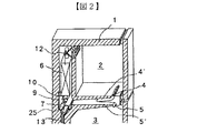
従来の冷蔵庫として特開平8−105680号公報に示されている冷蔵庫を、図2、図3及び図4を参照して説明する。図2は冷蔵庫の蒸発器部分の断面斜視図、図3は除霜ヒータの要部断面図、図4は蒸発器周辺の要部正面図及び側面図である。冷蔵庫の冷媒はHFC134a(1、2、2、2−テトラフルオロエタン)を用いている。
【0003】
図2において、1は冷蔵庫本体、2は冷凍室、3は冷蔵室である。4,5は冷凍室2、冷蔵室3からの吸込口で、ここから冷凍室2、冷蔵室3の空気が吸い込まれ、通路4’,5’を経て、冷凍室背面に設置された蒸発器6へ送られる。7は蒸発器6の下部に設置された除霜ヒータで、該除霜ヒータ7の両端はキャップ8を備えている。10は除霜ヒータ7の上方を覆うように取り付けられた上面カバー(以下、天井カバーという)であり、この天井カバー10は、除霜時に蒸発器6から滴下する除霜水が、高温になった除霜ヒータ7に接触して蒸発音を発生するのを防止するものである。12は蒸発器6で冷した空気を冷凍室2へ送るファンで、13は除霜時に蒸発器6から滴下する除霜水を冷蔵庫外へ排出するドレンである。
【0004】
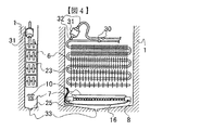
除霜ヒータ7は図3に示すガラス管ヒータが用いられており、ガラス管14内にヒータ線15が収められ、絶縁されたコード線16を介して通電され発熱する。ヒータ線は、キャップ8、コード線16により両端部で絶縁及び防水がなされている。蒸発器6は図4に示すように、出入口30、アキュムレータ31の出入口32でろう付け接続されている。
【0005】
また別の従来例の冷蔵庫を図5に示す、図5は蒸発機周辺の要部正面図及び側面図である。図5において除霜ヒータ7はシースヒータで蒸発器6のフィン23の角部に接触するように固定され蒸発器6の表裏両面に設置されている。33は樋25に設置されたヒータである。
【0006】
【発明が解決しようとする課題】
現在冷蔵庫に使用されている冷媒HFC134aはオゾン層破壊能力はないものの二酸化炭素比で約1、300倍の地球温暖化作用を有するため、オゾン層破壊能力が無く、且つ地球温暖化作用の小さいイソブタンやプロパンといった炭化水素系冷媒への代替が近年社会的に求められるようになっている。
【0007】
冷蔵庫用としては熱物性から冷凍サイクルの効率の高いイソブタンが有力視されているが、イソブタンは可燃性を有するため、冷凍サイクルからの冷媒漏れ防止とともに、万一冷媒漏れ時には電装品から着火することを防止することが重要な課題となっている。現状のガラス管ヒータの表面温度は、イソブタンの空気中での発火温度を超える場合があるため、安全面からヒータ表面温度を低下させねばならないという課題があった。
【0008】
また、ヒータ線温度はガラス管表面温度より高くなるため、キャップ8とガラス管14が完全に密閉されていない場合、漏洩冷媒がガラス管内に侵入して、剥き出しのヒータ線で着火する虞があるという課題がある。
【0009】
図5に示す冷蔵庫ではシースヒータを用い、ヒータ表面温度を下げて除霜を行うことができるが、ヒータを蒸発器表裏に配置しなければならない。そのため冷媒の冷蔵庫内への漏れ防止のため配管接続部30,31を本体1内に設けた場合、蒸発器6は剛に(動かせないように)固定され、蒸発器6の裏側のヒータ7は故障時には交換できなくなるという虞れがある。
【0010】
また、蒸発器に付着した霜の内側から加熱するため、除霜中に霜が塊となって落下する場合があり、樋25に落下した霜の塊を溶かすための樋ヒータ33が別途必要となり、部品点数と設置スペースの増加が避けられない。さらに蒸発器6の表裏全面にわたってヒータ7を設置するため、冷蔵庫の通常冷却運転時にはヒータ7により蒸発器6の通風抵抗が増加し、ファン12による風量が減少するという問題があった。
【0011】
本発明の目的は、上記従来技術の問題点を解決するためになされたもので、除霜ヒータ温度が冷媒のイソブタンの発火温度以上に上昇することが無く、万一可燃性の冷媒が冷蔵庫内に漏れた場合でも除霜ヒータにより発火することがない安全な冷蔵庫を提供することを目的とする。
【0012】
【課題を解決するための手段】
前記課題を解決するために、本発明は主として次のような構成を採用する。
【0013】
冷蔵庫本体内部に設けられた蒸発器と、前記蒸発器の下方に位置して前記蒸発器に付着した霜を溶かす除霜ヒータと、を備えた冷蔵庫において、
冷媒として可燃性を有する冷媒を用い、
前記除霜ヒータの管内にはヒータ線が設けられ、前記管の外周には伝熱促進用のフィンが螺旋状に巻きつけるように設けられ、前記除霜ヒータの表面温度を冷媒の発火温度より低くする冷蔵庫。
【0017】
【発明の実施の形態】
本発明の実施形態に係る除霜ヒータについて、図面に基づいて説明する。ここで、従来例と同一の構成部分については同一符号を付し説明を省略する。図1は本発明の第一の実施形態の除霜ヒータの要部断面図であり、図6は本発明の冷蔵庫の蒸発器周辺要部の正面図及び側面図である。ここで、17はシース管、18は絶縁材、19はフィンである。シース管中に絶縁材18に充填されたヒータ線15が収められ、両端部をキャップ8により絶縁密封し、外部からコード線16を介して通電され、加熱が行われる。シース管17外周にはフィン19が設けられ、周囲空気との伝熱が促進される。
【0018】
除霜ヒータ7に通電が行われると、シース管17及びフィン19の温度が上昇し、輻射及び自然対流により、着霜した蒸発器6が加熱され、蒸発器に付着した霜が溶かされる。除霜ヒータ7にはフィン19が設けられ、表面積が大幅に増加するため、従来のガラス管ヒータに比べ除霜ヒータ表面温度を下げた場合でも、従来と同程度の除霜に要する加熱量を蒸発器に伝達できる。したがって、万一配管が破損するなどしてイソブタンのような可燃性の冷媒が漏れていたとしても、除霜ヒータ表面で発火温度に達しないため、発火する危険が無い。除霜ヒータの温度はイソブタンの最低発火温度約400°Cより100°C下げた300°C程度に設定することで安全性を高める。
【0019】
さらにヒータ線15が絶縁材18で充填密封されていて、剥ぎ出しにならないためヒータ線15に漏れた冷媒が接触して発火するという危険が無い。またヒータ7はガラス管ヒータと同様に蒸発器6の下部に設置されるため、故障時に容易に交換作業を行うことができる。
【0020】
さらに、ヒータとしてPTC(Positive Temperature Coefficiet)ヒータのように所定温度以上に温度が上昇しないヒータを用いることで、さらに除霜ヒータの安全性を高くした構成としてもよい。
【0021】
また、ヒータ線15が絶縁材18中にあり、絶縁が確実に行われるため、図7に示すように、ヒータ線15を一端で折り返す構成として、コード線16を一方のキャップ8から取り出す配線としてもよい。この構成により、ヒータ外部と防水、絶縁すべきキャップ8が一方だけになり、水の侵入に対する信頼性を高くすることができる。またコード線16はヒータ7の一端から2本まとめて引き出せるため、庫内に収納する際の配線を、図4に示す両端から引き出す場合に比べて短くすることができ、配線収納性及び取り付け作業性が向上する。
【0022】
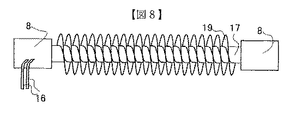
除霜ヒータ7のフィン19は図7に示すように独立したフィンでも良いし、図8に示すように、シース管17にフィンを螺旋状に巻き付ける構成として製作しやすくしたものを用いてもよい。また除霜ヒータ7は図9に示すようにフィン19を有する平板状容器34にヒータ線15を接続密封したものを用いても、上記したものと同様の効果を得ることができる。
【0023】
上記した除霜ヒータ7はいずれも蒸発器6の下方に蒸発器6とは分離して設置されるため、冷蔵庫の通常冷却運転時に、図5に示す従来の冷蔵庫の場合のように通風抵抗が増加することがなく、効率的な冷却を行うことができる。
【0024】
別の除霜ヒータの実施形態として図10に基づいて説明する。図10において、20は芯、21は導電性皮膜、24は絶縁皮膜である。芯20に設置されたフィン19の表面に絶縁皮膜24を形成し、さらに前記絶縁皮膜24上に導電性皮膜21を塗布してコード線16により通電することで除霜ヒータ7を構成する。
【0025】
該除霜ヒータは上述したフィン付除霜ヒータ管と同様の作用をなし、フィンにより表面積を増加し、フィン表面温度を低下できるものであり、また構成が簡略であることから上述したシース管ヒータを用いる場合よりも安価な除霜ヒータを提供できる。
【0026】
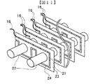
さらに別の除霜ヒータの実施形態として図11に基づいて説明する。図11において、22は蒸発器6の伝熱管、23は蒸発器伝熱管22のフィン、21は導電性皮膜、24は絶縁皮膜である。図11では説明のため、手前側のフィン23の下側部分について導電性皮膜21を透過して表示しているが、蒸発器伝熱管22のフィン23上に、絶縁膜24及び導電性皮膜21を順に塗布して、回路パターンを描いて除霜ヒータを形成する。回路パターンの形成によりフィン23の熱抵抗が増加し、本来の熱交換器としての性能が低下するため、回路パターン部は小面積に抑えるものとする。
【0027】
着霜状態のフィン23を直接加熱できるため、ヒータとなる導電性皮膜の温度をイソブタンなどの可燃性冷媒の発火温度より十分低くすることができ、安全に除霜を実施できる。或いは、図示しないがフィン23の両面に導電性皮膜21を塗布した構成としてもよい。
【0028】
また、本発明は、従来の冷媒HFC134aを用いた冷蔵庫の除霜ヒータに適用してもよく、ヒータ表面温度を従来より下げ、除霜に要する消費電力を低減することができる。
【0029】
以上説明したように、本発明の実施形態によれば、次のような構成例並びに機能乃至作用を奏するものを含むものである。
【0030】
冷蔵庫本体内部に設けられた蒸発器と、この蒸発器の下方に位置して当該蒸発器に付着した霜を溶かす除霜ヒータとを備えた冷蔵庫において、除霜ヒータのヒータ線を絶縁材で充填された管内に設け、該ヒータ管に伝熱促進用のフィンを設けるものである。
【0031】
このような除霜ヒータを用いて除霜を行えば、フィンにより周辺空気と熱交換する除霜ヒータ表面積が増加するため、従来のガラス管ヒータに比べ除霜ヒータ表面温度を下げた場合でも、従来と同程度の除霜に要する加熱量を蒸発器に伝達できる。したがって、万一イソブタンのような可燃性の冷媒が漏れていたとしても、除霜ヒータ表面で発火温度に達しないため、発火する危険が無い。さらにヒータ線15が絶縁材18で充填密封されていて、剥き出しにならないためヒータ線15に漏れた冷媒が接触して発火するという危険が無い。また、ヒータとしてPTCヒータのように所定温度以上に温度が上昇しないものを用いることで、さらに除霜ヒータの安全性を高くしてもよい。
【0032】
また、冷蔵庫本体内部に設けられた蒸発器と、この蒸発器の下方に位置して当該蒸発器に付着した霜を溶かす除霜ヒータとを備えた冷蔵庫において、前記除霜ヒータは、フィンを有する本体に発熱体としての導電性皮膜を塗布したものである。即ち、芯に設置されたフィンの表面に導電性皮膜を塗布してコード線により通電することで除霜ヒータを構成する。該除霜ヒータは上述したフィン付除霜ヒータ管と同様の作用をなし、フィンにより表面積を増加し、フィン表面温度を低下できるものであり、また構成が簡略であることから上述したシース管ヒータを用いる場合よりも安価な除霜ヒータを提供できる。
【0033】
また、冷蔵庫本体内部に設けられたフィンを有する蒸発器を備えた冷蔵庫において、該蒸発器のフィンにフィンと絶縁された発熱体としての導電性皮膜を塗布して成る除霜ヒータを設けるものである。即ち、蒸発器伝熱管のフィン上に絶縁膜及び導電性皮膜を順に塗布して、蒸発器フィン上に除霜ヒータを形成する。蒸発器をフィンから直接加熱できるため、ヒータとなる導電性皮膜の温度をイソブタンなどの可燃性冷媒の発火温度より十分低くすることができ、安全に除霜を実施できる。また従来のように蒸発器の下方に除霜ヒータ、天井カバー等の設置スペースが不要になる。
【0034】
本発明によれば、フィン付密封シース管ヒータにより除霜を行うことで、フィンにより周辺空気と熱交換する除霜ヒータ表面積が増大するため、従来のガラス管ヒータに比べ除霜ヒータ表面温度を下げた場合でも、従来と同程度の除霜に要する加熱量を蒸発器に伝達でき、万一イソブタンのような可燃性の冷媒が漏れていたとしても、除霜ヒータ表面で発火温度に達しないため、発火する危険が無い。さらに蒸発器の設置、交換作業は従来と同様に容易に行うことができる。
【0035】
また本発明の別の実施の形態によれば、芯に設置されたフィンの表面に導電性皮膜を塗布して形成した除霜ヒータを用いて、上述したフィン付除霜ヒータ管と同様の作用をなす除霜ヒータを安価に提供できる。
【0036】
また本発明の別の実施の形態によれば、導電性皮膜を塗布して、蒸発器フィン上に除霜ヒータを形成し、蒸発器をフィンから直接加熱し、ヒータとなる導電性皮膜の温度をイソブタンなどの可燃性冷媒の発火温度より十分低下することができ、安全に除霜を実施できる。
【発明の効果】
本発明によれば、除霜ヒータ温度が冷媒のイソブタンの発火温度以上に上昇することが無く、万一可燃性の冷媒が冷蔵庫に漏れた場合でも除霜ヒータにより発火することがない安全な冷蔵庫とすることができる。
【図面の簡単な説明】
【図1】本発明の実施形態に係る除霜ヒータの構成を示す図である。
【図2】従来の冷蔵庫における蒸発器周辺の構成を示す図である。
【図3】従来の除霜ヒータの一例を示す図である。
【図4】従来の蒸発器周辺の要部を示す図である。
【図5】他の従来例における蒸発器周辺の要部を示す図である。
【図6】本発明の実施形態に係る蒸発器周辺の構成を示す図である。
【図7】本実施形態に係る除霜ヒータの構成例を示す図である。
【図8】本実施形態に係る除霜ヒータの他の構成例を示す図である。
【図9】本実施形態に係る除霜ヒータの更に他の構成例を示す図である。
【図10】本実施形態に係る除霜ヒータのフィン構成例を示す図である。
【図11】本発明の実施形態に係る蒸発器伝熱管フィンを除霜ヒータとして用いる構成を示す図である。
【符号の説明】
1 冷蔵庫本体
2 冷凍室
3 冷蔵室
6 蒸発器
7 除霜ヒータ
8 キャップ
10 天井カバー
12 冷却ファン
14 ガラス管
15 ヒータ線
16 コード線
17 シース管
18 絶縁材
19 除霜ヒータフィン
20 芯
21 導電性皮膜
22 蒸発器伝熱管
23 蒸発管フィン
24 絶縁膜[0001]
BACKGROUND OF THE INVENTION
The present invention relates to a defrosting heater for a refrigerator using a flammable refrigerant.
[0002]
[Prior art]
A refrigerator disclosed in JP-A-8-105680 as a conventional refrigerator will be described with reference to FIGS. 2 is a cross-sectional perspective view of the evaporator part of the refrigerator, FIG. 3 is a cross-sectional view of the main part of the defrost heater, and FIG. 4 is a front view and a side view of the main part around the evaporator. HFC134a (1, 2, 2, 2-tetrafluoroethane) is used as the refrigerant of the refrigerator.
[0003]
In FIG. 2, 1 is a refrigerator main body, 2 is a freezer compartment, 3 is a refrigerator compartment.
[0004]
A glass tube heater shown in FIG. 3 is used as the
[0005]
FIG. 5 shows another conventional refrigerator. FIG. 5 is a front view and a side view of main parts around the evaporator. In FIG. 5, the
[0006]
[Problems to be solved by the invention]
Refrigerant HFC134a currently used in refrigerators has no global warming action about 1,300 times the carbon dioxide ratio, although it does not have the ability to destroy the ozone layer. Therefore, isobutane has no ozone layer destruction ability and low global warming action. In recent years, an alternative to hydrocarbon refrigerants such as propane and propane has been socially demanded.
[0007]
Isobutane, which has high refrigeration cycle efficiency due to its thermophysical properties, is considered promising for refrigerators. However, because isobutane is flammable, it should prevent refrigerant leakage from the refrigeration cycle and ignite from electrical components in the unlikely event of refrigerant leakage. Prevention has become an important issue. Since the surface temperature of the current glass tube heater sometimes exceeds the ignition temperature of isobutane in the air, there has been a problem that the heater surface temperature has to be lowered for safety.
[0008]
In addition, since the heater wire temperature is higher than the glass tube surface temperature, if the
[0009]
In the refrigerator shown in FIG. 5, a sheath heater is used to perform defrosting by lowering the heater surface temperature. However, the heater must be arranged on the front and back of the evaporator. Therefore, when the
[0010]
Moreover, since it heats from the inside of the frost adhering to an evaporator, frost may fall as a lump during defrosting, and the
[0011]
The object of the present invention is to solve the above-mentioned problems of the prior art, and the defrost heater temperature does not rise above the ignition temperature of the isobutane refrigerant, so that the flammable refrigerant should be stored in the refrigerator. An object of the present invention is to provide a safe refrigerator that is not ignited by a defrosting heater even if it leaks into the oven.
[0012]
[Means for Solving the Problems]
In order to solve the above problems, the present invention mainly adopts the following configuration.
[0013]
In a refrigerator comprising: an evaporator provided inside a refrigerator body; and a defrost heater positioned below the evaporator to melt frost attached to the evaporator,
Using a flammable refrigerant as the refrigerant,
A heater wire is provided in the pipe of the defrost heater, and a fin for heat transfer promotion is spirally wound around the outer circumference of the pipe, and the surface temperature of the defrost heater is determined from the ignition temperature of the refrigerant. Refrigerator to lower .
[0017]
DETAILED DESCRIPTION OF THE INVENTION
The defrost heater which concerns on embodiment of this invention is demonstrated based on drawing. Here, the same components as those of the conventional example are denoted by the same reference numerals and description thereof is omitted. FIG. 1 is a cross-sectional view of a main part of the defrosting heater according to the first embodiment of the present invention, and FIG. 6 is a front view and a side view of the main part around the evaporator of the refrigerator of the present invention. Here, 17 is a sheath tube, 18 is an insulating material, and 19 is a fin.
[0018]
When the
[0019]
Furthermore, since the
[0020]
Furthermore, it is good also as a structure which raised the safety | security of the defrost heater further by using the heater which does not rise in temperature more than predetermined temperature like a PTC (Positive Temperature Coefficient) heater as a heater.
[0021]
Further, since the
[0022]
The
[0023]
Since all the
[0024]
An embodiment of another defrosting heater will be described with reference to FIG. In FIG. 10, 20 is a core, 21 is a conductive film, and 24 is an insulating film. The
[0025]
The defrost heater has the same function as the above-described defrost heater pipe with fins, can increase the surface area by using the fins, can reduce the fin surface temperature, and has a simple structure. It is possible to provide a defrosting heater that is less expensive than the case of using.
[0026]
Furthermore, it demonstrates based on FIG. 11 as embodiment of another defrost heater. In FIG. 11, 22 is a heat transfer tube of the
[0027]
Since the
[0028]
In addition, the present invention may be applied to a refrigerator defrost heater using a conventional refrigerant HFC134a, and the heater surface temperature can be lowered as compared with the conventional one to reduce the power consumption required for defrosting.
[0029]
As described above, according to the embodiment of the present invention, the following configuration examples and functions and functions are included.
[0030]
In a refrigerator provided with an evaporator provided inside the refrigerator main body and a defrost heater positioned below the evaporator to melt frost attached to the evaporator, the heater wire of the defrost heater is filled with an insulating material. The heat pipe is provided with a fin for promoting heat transfer.
[0031]
If defrosting is performed using such a defrosting heater, the surface area of the defrosting heater that exchanges heat with the surrounding air is increased by fins, so even when the defrosting heater surface temperature is lowered compared to the conventional glass tube heater, The amount of heating required for defrosting to the same extent as before can be transmitted to the evaporator. Therefore, even if a flammable refrigerant such as isobutane leaks, it does not reach the ignition temperature on the surface of the defrost heater, so there is no danger of ignition. Furthermore, since the
[0032]
Moreover, the refrigerator provided with the evaporator provided in the refrigerator main body, and the defrost heater which melt | dissolves the frost adhering to the said evaporator located under this evaporator, The said defrost heater has a fin. A conductive film as a heating element is applied to the main body. That is, the defrosting heater is configured by applying a conductive film on the surface of the fin installed on the core and energizing the cord wire. The defrost heater has the same function as the above-described defrost heater pipe with fins, can increase the surface area by using the fins, can reduce the fin surface temperature, and has a simple structure. It is possible to provide a defrosting heater that is less expensive than the case of using.
[0033]
Further, in a refrigerator provided with an evaporator having fins provided inside the refrigerator body, a defrosting heater is provided which is formed by applying a conductive film as a heating element insulated from the fins to the fins of the evaporator. is there. That is, an insulating film and a conductive film are sequentially applied on the fins of the evaporator heat transfer tube to form a defrosting heater on the evaporator fins. Since the evaporator can be directly heated from the fins, the temperature of the conductive film serving as a heater can be made sufficiently lower than the ignition temperature of a combustible refrigerant such as isobutane, and defrosting can be performed safely. Moreover, the installation space, such as a defrost heater and a ceiling cover, becomes unnecessary under the evaporator like the past.
[0034]
According to the present invention, defrosting with a finned sealed sheath tube heater increases the surface area of the defrost heater that exchanges heat with the surrounding air by the fins. Even when the temperature is lowered, the amount of heat required for defrosting can be transmitted to the evaporator, and even if a flammable refrigerant such as isobutane leaks, it will not reach the ignition temperature on the surface of the defrost heater. Therefore, there is no danger of fire. Furthermore, installation and replacement of the evaporator can be easily performed as in the conventional case.
[0035]
According to another embodiment of the present invention, the defrost heater formed by applying a conductive film to the surface of the fin installed on the core is used and has the same effect as the above-described defrost heater tube with fins. The defrost heater which makes can be provided at low cost.
[0036]
According to another embodiment of the present invention, a conductive film is applied, a defrost heater is formed on the evaporator fin, the evaporator is directly heated from the fin, and the temperature of the conductive film serving as the heater is increased. Can be sufficiently lowered from the ignition temperature of a combustible refrigerant such as isobutane, and defrosting can be performed safely.
【The invention's effect】
According to the present invention, the defrost heater temperature does not rise above the ignition temperature of the isobutane refrigerant, and a safe refrigerator that is not ignited by the defrost heater even if flammable refrigerant leaks into the refrigerator. It can be.
[Brief description of the drawings]
FIG. 1 is a diagram showing a configuration of a defrost heater according to an embodiment of the present invention.
FIG. 2 is a diagram showing a configuration around an evaporator in a conventional refrigerator.
FIG. 3 is a view showing an example of a conventional defrost heater.
FIG. 4 is a view showing a main part around a conventional evaporator.
FIG. 5 is a view showing a main part around an evaporator in another conventional example.
FIG. 6 is a diagram showing a configuration around an evaporator according to an embodiment of the present invention.
FIG. 7 is a diagram illustrating a configuration example of a defrost heater according to the present embodiment.
FIG. 8 is a diagram showing another configuration example of the defrosting heater according to the present embodiment.
FIG. 9 is a diagram showing still another configuration example of the defrosting heater according to the present embodiment.
FIG. 10 is a diagram illustrating a fin configuration example of the defrosting heater according to the present embodiment.
FIG. 11 is a diagram showing a configuration in which an evaporator heat transfer tube fin according to an embodiment of the present invention is used as a defrost heater.
[Explanation of symbols]
DESCRIPTION OF SYMBOLS 1
Claims (1)
冷媒として可燃性を有する冷媒を用い、
前記除霜ヒータの管内にはヒータ線が設けられ、前記管の外周には伝熱促進用のフィンが螺旋状に巻きつけるように設けられ、前記除霜ヒータの表面温度を冷媒の発火温度より低くする
ことを特徴とする冷蔵庫。In a refrigerator comprising: an evaporator provided inside a refrigerator body; and a defrost heater positioned below the evaporator to melt frost attached to the evaporator,
Using a flammable refrigerant as the refrigerant,
A heater wire is provided in the pipe of the defrost heater, and a fin for heat transfer promotion is spirally wound around the outer circumference of the pipe, and the surface temperature of the defrost heater is determined from the ignition temperature of the refrigerant. A refrigerator characterized by being lowered .
Priority Applications (1)
| Application Number | Priority Date | Filing Date | Title |
|---|---|---|---|
| JP09014199A JP3955412B2 (en) | 1999-03-30 | 1999-03-30 | refrigerator |
Applications Claiming Priority (1)
| Application Number | Priority Date | Filing Date | Title |
|---|---|---|---|
| JP09014199A JP3955412B2 (en) | 1999-03-30 | 1999-03-30 | refrigerator |
Publications (3)
| Publication Number | Publication Date |
|---|---|
| JP2000283635A JP2000283635A (en) | 2000-10-13 |
| JP2000283635A5 JP2000283635A5 (en) | 2005-10-06 |
| JP3955412B2 true JP3955412B2 (en) | 2007-08-08 |
Family
ID=13990244
Family Applications (1)
| Application Number | Title | Priority Date | Filing Date |
|---|---|---|---|
| JP09014199A Expired - Fee Related JP3955412B2 (en) | 1999-03-30 | 1999-03-30 | refrigerator |
Country Status (1)
| Country | Link |
|---|---|
| JP (1) | JP3955412B2 (en) |
Families Citing this family (5)
| Publication number | Priority date | Publication date | Assignee | Title |
|---|---|---|---|---|
| JP3944498B2 (en) * | 2004-08-25 | 2007-07-11 | 日立アプライアンス株式会社 | refrigerator |
| JP4332485B2 (en) * | 2004-10-12 | 2009-09-16 | 日立アプライアンス株式会社 | refrigerator |
| JP4500645B2 (en) * | 2004-10-12 | 2010-07-14 | 日立アプライアンス株式会社 | refrigerator |
| JP4945600B2 (en) * | 2009-05-11 | 2012-06-06 | 日立アプライアンス株式会社 | refrigerator |
| CN110895074A (en) * | 2019-12-25 | 2020-03-20 | 长虹美菱股份有限公司 | Refrigerator with rotary fin defrosting heating structure |
-
1999
- 1999-03-30 JP JP09014199A patent/JP3955412B2/en not_active Expired - Fee Related
Also Published As
| Publication number | Publication date |
|---|---|
| JP2000283635A (en) | 2000-10-13 |
Similar Documents
| Publication | Publication Date | Title |
|---|---|---|
| KR20020011409A (en) | Refrigerator and defrosting heater | |
| CN100362297C (en) | Refrigerator | |
| JP2002267331A (en) | Refrigerator | |
| JP3955412B2 (en) | refrigerator | |
| US7308804B2 (en) | Defrosting heater, and refrigerator having the defrosting heater | |
| JP2004190959A (en) | Refrigerator | |
| JP2004044899A (en) | Defrosting heater for household refrigerator | |
| JP2001133128A (en) | Refrigerator | |
| JP3404299B2 (en) | refrigerator | |
| JP4332485B2 (en) | refrigerator | |
| JPH0854172A (en) | Refrigerator | |
| JP3399934B2 (en) | Defrost heater and refrigerator | |
| CN100356123C (en) | Refrigerator | |
| JP2004271014A (en) | Refrigerator | |
| JP3404394B2 (en) | Defrost heater and refrigerator | |
| JP3482405B2 (en) | refrigerator | |
| JP2002364973A (en) | Refrigerator | |
| JP3482406B2 (en) | Freezer refrigerator | |
| JP2003042637A (en) | Refrigerator | |
| JP4945600B2 (en) | refrigerator | |
| JP2002195735A (en) | Defrosting heater and refrigerator | |
| JP2005180739A (en) | Refrigerator | |
| JP2004257618A (en) | Defrosting heater and refrigerator equipped therewith | |
| JP2006112657A (en) | Refrigerator | |
| JP2004190960A (en) | Refrigerator |
Legal Events
| Date | Code | Title | Description |
|---|---|---|---|
| A521 | Written amendment |
Free format text: JAPANESE INTERMEDIATE CODE: A523 Effective date: 20050520 |
|
| A621 | Written request for application examination |
Free format text: JAPANESE INTERMEDIATE CODE: A621 Effective date: 20050520 |
|
| A871 | Explanation of circumstances concerning accelerated examination |
Free format text: JAPANESE INTERMEDIATE CODE: A871 Effective date: 20070111 |
|
| A975 | Report on accelerated examination |
Free format text: JAPANESE INTERMEDIATE CODE: A971005 Effective date: 20070118 |
|
| A131 | Notification of reasons for refusal |
Free format text: JAPANESE INTERMEDIATE CODE: A131 Effective date: 20070123 |
|
| A521 | Written amendment |
Free format text: JAPANESE INTERMEDIATE CODE: A523 Effective date: 20070322 |
|
| TRDD | Decision of grant or rejection written | ||
| A01 | Written decision to grant a patent or to grant a registration (utility model) |
Free format text: JAPANESE INTERMEDIATE CODE: A01 Effective date: 20070424 |
|
| A61 | First payment of annual fees (during grant procedure) |
Free format text: JAPANESE INTERMEDIATE CODE: A61 Effective date: 20070502 |
|
| R150 | Certificate of patent or registration of utility model |
Free format text: JAPANESE INTERMEDIATE CODE: R150 |
|
| A521 | Written amendment |
Free format text: JAPANESE INTERMEDIATE CODE: A523 Effective date: 20070322 |
|
| FPAY | Renewal fee payment (event date is renewal date of database) |
Free format text: PAYMENT UNTIL: 20110511 Year of fee payment: 4 |
|
| FPAY | Renewal fee payment (event date is renewal date of database) |
Free format text: PAYMENT UNTIL: 20110511 Year of fee payment: 4 |
|
| FPAY | Renewal fee payment (event date is renewal date of database) |
Free format text: PAYMENT UNTIL: 20120511 Year of fee payment: 5 |
|
| FPAY | Renewal fee payment (event date is renewal date of database) |
Free format text: PAYMENT UNTIL: 20120511 Year of fee payment: 5 |
|
| FPAY | Renewal fee payment (event date is renewal date of database) |
Free format text: PAYMENT UNTIL: 20130511 Year of fee payment: 6 |
|
| FPAY | Renewal fee payment (event date is renewal date of database) |
Free format text: PAYMENT UNTIL: 20130511 Year of fee payment: 6 |
|
| LAPS | Cancellation because of no payment of annual fees |