JP3951971B2 - refrigerator - Google Patents

refrigerator Download PDF

Info

Publication number
JP3951971B2
JP3951971B2 JP2003184194A JP2003184194A JP3951971B2 JP 3951971 B2 JP3951971 B2 JP 3951971B2 JP 2003184194 A JP2003184194 A JP 2003184194A JP 2003184194 A JP2003184194 A JP 2003184194A JP 3951971 B2 JP3951971 B2 JP 3951971B2
Authority
JP
Japan
Prior art keywords
door
heat insulating
box
convex portion
refrigerator
Prior art date
Legal status (The legal status is an assumption and is not a legal conclusion. Google has not performed a legal analysis and makes no representation as to the accuracy of the status listed.)
Expired - Fee Related
Application number
JP2003184194A
Other languages
Japanese (ja)
Other versions
JP2005016876A (en
Inventor
晃一 西村
寿和 境
隆幸 高谷
▲よし▼孝 窪田
正治 亀井
Current Assignee (The listed assignees may be inaccurate. Google has not performed a legal analysis and makes no representation or warranty as to the accuracy of the list.)
Panasonic Corp
Panasonic Holdings Corp
Original Assignee
Panasonic Corp
Matsushita Electric Industrial Co Ltd
Priority date (The priority date is an assumption and is not a legal conclusion. Google has not performed a legal analysis and makes no representation as to the accuracy of the date listed.)
Filing date
Publication date
Application filed by Panasonic Corp, Matsushita Electric Industrial Co Ltd filed Critical Panasonic Corp
Priority to JP2003184194A priority Critical patent/JP3951971B2/en
Priority to CNB2004100423036A priority patent/CN1318812C/en
Publication of JP2005016876A publication Critical patent/JP2005016876A/en
Application granted granted Critical
Publication of JP3951971B2 publication Critical patent/JP3951971B2/en
Anticipated expiration legal-status Critical
Expired - Fee Related legal-status Critical Current

Links

Images

Classifications

    • FMECHANICAL ENGINEERING; LIGHTING; HEATING; WEAPONS; BLASTING
    • F25REFRIGERATION OR COOLING; COMBINED HEATING AND REFRIGERATION SYSTEMS; HEAT PUMP SYSTEMS; MANUFACTURE OR STORAGE OF ICE; LIQUEFACTION SOLIDIFICATION OF GASES
    • F25DREFRIGERATORS; COLD ROOMS; ICE-BOXES; COOLING OR FREEZING APPARATUS NOT OTHERWISE PROVIDED FOR
    • F25D2323/00General constructional features not provided for in other groups of this subclass
    • F25D2323/02Details of doors or covers not otherwise covered
    • F25D2323/021French doors

Landscapes

  • Refrigerator Housings (AREA)

Description

【0001】
【発明の属する技術分野】
本発明は、冷蔵庫に関し、業務用の大型冷凍冷蔵庫の省エネに関わる断熱箱体および断熱扉の構造に関するものである。
【0002】
【従来の技術】
近年、冷凍業界では環境への配慮から、家庭用冷蔵庫では2004年に、物品自動販売機では2005年に省エネトップランナー制度が適用される予定であり、機器の消費電力量低減が進んでいる。同様に、消費電力量の大きい業務用の大型冷凍冷蔵庫についても省電力化が望まれている。
【0003】
従来の業務用冷蔵庫としては、以下に示す例がある(例えば、特許文献1参照。)。
【0004】
以下、図面を参照しながら上記従来の冷蔵庫を説明する。
【0005】
図7は従来の冷蔵庫の縦断面図である。図8は従来の冷蔵庫の横断面図である。図7及び図8に示すように、従来の冷蔵庫は、断熱材により形成し、前面に開口部を持つ断熱箱体1と、断熱箱体1上部に収納された冷却システム2と、断熱箱体1にヒンジ(図示せず)により回動自在に軸支された観音開式の2枚の扉3を備えている。
【0006】
断熱箱体1開口部には開口部を左右に仕切るピラー4を備えている。
【0007】
扉3には断熱箱体1及びピラー4に対応した位置にガスケット5を設けており、扉3を閉めた時に断熱箱体1及びピラー4と密着することにより庫内と庫外を仕切っている。
【0008】
断熱箱体1背面には冷却風を循環させるダクト6を備えている。
【0009】
断熱箱体1内部には、庫内背面からピラー4の庫内側端面までの奥行きの、被冷却物を収納する収納棚7を備えている。
【0010】
一般的に家庭用冷凍冷蔵庫においては、扉3の庫内側のにはボトルなど、被冷却物を収納する収納ポケットを備えているが、業務用冷凍冷蔵庫においては庫内に収納される被冷却物は箱に入っている物が多く、扉3の庫内側に収納ポケットがあると、庫内前面の被冷却物と収納ポケットの間にすき間が無くなり、冷却風が循環しにくくなるため、扉3の庫内側には収納ポケッを持たず、平面となっている。
【0011】
従って、庫内の断熱箱体1前縁からピラー4の庫内側端面までは収納に使われず、風路として使われている。
【0012】
冷却システム2は、圧縮機(図示せず)、凝縮器(図示せず)、減圧手段(図示せず)、蒸発器8及び冷却ファン9により構成されており、冷却ファン9による冷却風は庫内へ吹き出され、ダクト6、蒸発器8を通り再び冷却ファン9に吸い込まれる。
【0013】
【特許文献1】
特開平9−89440号公報
【0014】
【発明が解決しようとする課題】
しかしながら、上記従来の冷蔵庫では、冷却ファン9から吹き出された冷却風は直接ガスケット5や断熱箱体1と扉3のシール部に当たり、ガスケット5やシール部を冷却する。ガスケット5やシール部が冷却されると、ガスケット5やシール部の伝熱により庫外の熱が庫内へ侵入し、庫内が暖められ熱ロスとなり、消費電力量が増加するおそれがあった。
【0015】
また、シール部が冷却されることにより、シール部で外気の水分が凝縮し結露するため、通常はシール部にはヒーターなどの過熱手段が設けられており、温度を空気の露点温度以上とし、水分が凝縮しないようになっている。従来の構成においては、冷却ファン9による冷却風が直接シール部に当たることにより、シール部が冷却され、温度を空気の露点温度以上とするにはより大きなヒーター能力が必要となり、ヒーターの消費電力量が大きくなるおそれがあった。
【0016】
本発明は上記従来の課題を解決するものであり、冷却ファン9による冷却風をガスケット5やシール部に直接当てないことにより消費電力量を低減することを目的とする。
【0017】
本発明の請求項1に記載の冷蔵庫の発明は、外箱と内箱の間に断熱材を封入して構成した断熱箱体と、扉外板と扉内板の間に断熱材を封入して構成したヒンジによる回転式の断熱扉と、前記断熱箱体の開口部に前記断熱扉を取付けて内部に構成した貯蔵室とからなり、前記断熱箱体の開口周縁に設けた平面部と、前記平面部と内箱をつなぐ凹部と、前記凹部の奥端に設けた段差部と、前記断熱扉の前記貯蔵室側周縁に設けた平面部と、前記平面部より立ち上げられた先端に折返部を設けて前記凹部の段差部より手前側に配置されるように前記扉内板に設けた凸部と、前記断熱箱体の平面部と断熱扉の平面部及び前記凹部と前記扉内板の凸部をそれぞれ対向させてスロートを形成し、前記凸部は扉の上下辺及びヒンジに対向する辺の3辺に備えられ、略コの字型に形成されているものであり、外気による侵入熱を低減することができる。
また、扉を開いた時に凸部が庫内に突出することがなく、食品を入れる際に邪魔になることがないので使い勝手のよい冷蔵庫を提供することができるという作用を有する。
【0018】
本発明の請求項2に記載の発明は、請求項1に記載の発明において、金属製の外箱と、金属製の内箱で形成し、凹部は樹脂材料で形成されているものであり、開口部近傍に熱伝導性の低い樹脂材料で形成しているため外部からの侵入熱を低減することができる。
【0020】
本発明の請求項3に記載の発明は、請求項1または2に記載の発明において、凹部と凸部を対向して形成される凸部は5mm以上15mm以下としたものであり、凸部と凹部が接触し、扉が破損することはなく、信頼性の高い冷蔵庫とすることができるという作用を有する。
【0021】
本発明の請求項4に記載の発明は、請求項1から3のいずれか1項に記載の発明において、凸部の幅を5mm以上20mm以下としたものであり、凸部の効果が大きく庫内容積の減少も最小にでき、消費電力量が低く、容積効率の高い冷蔵庫とすることができるという作用を有する。
【0022】
本発明の請求項5に記載の冷蔵庫の発明は、請求項1から4のいずれか1項に記載の発明において、凸部の長さを35mm以上50mm以下としたものであり、凸部の効果が大きく庫内容積の減少も最小にでき、さらに消費電力量が低く、容積効率の高い冷蔵庫とすることができるという作用を有する。
【0023】
本発明の請求項6に記載の発明は、請求項1から5のいずれか1項に記載の発明において、凸部の折返部にシール部材を設け、閉扉時に凹部の段差部に当接して凸部と貯蔵室内の間をシールするものであり、外気による侵入熱をさらに低減することができる。
【0024】
本発明の請求項7に記載の発明は、請求項1から6のいずれか1項に記載の発明において、断熱箱体の開口部を左右に仕切る仕切板を有し、前記開口部に観音開式の扉を備えたものであり、仕切板と扉間からの外気熱の庫内への貫流が抑止される。
【0025】
【発明の実施の形態】
以下、本発明による冷蔵庫の実施の形態について、図面を参照しながら説明する。なお、従来と同一構成については、同一符号を付して詳細な説明を省略する。
【0026】
(実施の形態1)
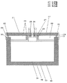
図1は、本発明の実施の形態1による冷蔵庫の縦断面図である。図2は図1の要部拡大図である。図3は同実施の形態のヒンジに対向する扉シール部の横断面図である。図4は同実施の形態の凸部の幅と省エネ効果の関係を表す特性図である。図5は同実施の形態の凸部の長さと省エネ効果の関係を表す特性図である。
【0027】
図1から図3に示すように、扉10は断熱箱体11と、ヒンジ12を介して回動自在に軸支されており、庫内側にヒンジ12に対向する辺13aおよび上下辺13bで略コの字型に突出した凸部13を備えている。
【0028】
断熱箱体11は金属製の外箱14と金属製の内箱15で断熱材16を挟み込むように構成されており、樹脂製の凹部17により断熱箱体11の開口部近傍で連結されている。
【0029】
凹部17は少なくとも扉10を閉じた時に凸部13の端部までの長さがあり、凸部13端部で庫内側に向かって突出した形状となっている。
【0030】
また、凸部13の折返部13cにはシール部材18を備えており、扉10を閉じた時に凹部17の段差部17aに当接してスロート100をシールしている。
【0031】
凸部13の長さは35mmから50mmであり、幅は5mmから20mmとなっている。
【0032】
凸部13と凹部17で形成されるスロート100は幅Aが5mm以上15mm以下となっており、ヒンジ12に対向する辺13aの凸部13はヒンジ12に対してヒンジ12から凸部13外側までの距離を半径とする円弧状となっている。
【0033】
また、凸部13のヒンジ12と対向する凹部17は凸部13と5mm以上15mm以下のスロート100を保つような円弧状となっている。
【0034】
また、断熱箱体11の前縁部には防露ヒーター19を備えており、断熱箱体11の前縁部に水分が凝縮しないように加温している。
【0035】
以上のように構成された冷蔵庫について、以下その動作を説明する。
【0036】
冷蔵庫運転中、冷却ファン9の運転により庫内を冷却風が循環する。この時、扉10には凸部13が突出しており、ガスケット5や扉10と断熱箱体11のシール部には直接風が当たらず冷却されることはない。
【0037】
また、凹部17はABS樹脂などの樹脂材料で構成されており、内箱15の熱伝導により扉10と断熱箱体11のシール部が冷却されることはない。
【0038】
また、凹部17は凸部13の端部で段差部17aを形成し庫内側に突出しているため、凹部17と凸部13のスロート100はカギ型となり、凸部13と凹部17のスロート100が冷却されても扉10と断熱箱体11のシール部まで熱伝達しにくくなることにより冷却されにくくなる。
【0039】
また、凸部13と凹部17の間にシール部材18を設け、スロート100をシールしたので、冷却風が凸部13と凹部17の間のスロート100に流れ込むことはなく、扉10と断熱箱体11のシール部が冷却されることはない。
【0040】
これにより、扉10と断熱箱体11のシール部からの侵入熱量を低減できるとともに、断熱箱体11前縁部の温度を上げることができ、防露ヒーター19の入力を低減することができる。
【0041】
さらに、凸部13と凹部17には5mm以上15mm以下のスロート100が設けてある。
【0042】
ここで凸部13と凹部17のスロート100が5mm以下だったとすると、扉10の傾きにより凸部13と凹部17が当たり、破損してしまうおそれがある。
【0043】
しかしながら、通常使用において、扉10の傾きは、もっとも移動する位置で5mm以内に抑えることが可能なため、凸部13と凹部17が当たることはない。
【0044】
また、凸部13の長さと幅については、特性図4、5より長さBが35mm以上になると長さの増加に対する省エネ効果は小さくなり、幅が5mm以上になると幅の増加に対する省エネ効果は小さくなる。
【0045】
これに対して、庫内の棚の前縁部は断熱箱体9の前縁部から長さBが約50mmであり、凸部長さが50mm以内であれば、業務用冷蔵庫の特徴である庫内前面の風路を阻害せず凸部13を構成することが可能であり、扉10内に凸部13があることにより冷却風量を減少させることがない
また、凸部幅Cが20mmを越えると断熱箱体11の開口部の横幅いっぱいの被冷却物を入れた時に扉10を閉めると被冷却物と凸部13が当たってしまい、扉10が破損するおそれがある。
【0046】
しかしながら、本発明の冷蔵庫においては、凸部13の長さBを35mmから50mmの間とし、幅Cを5mmから20mmの間としているため、省エネ効果が高く、庫内容積を大きくでき、扉10の破損を防止することができる。
【0047】
また、扉10のヒンジ12側に凸部13を設けると、扉10を開けた時に凸部13が断熱箱体11の開口部に突出し、庫内に被冷却物を入れる際の邪魔になる。
【0048】
しかしながら、本発明の冷蔵庫においては、凸部13はヒンジ12に対向する辺13aおよび上下辺13bで略コの字型に形成されており、庫内に被冷却物を入れる際に邪魔になることはない。
【0049】
また、凸部13を設けた扉10を開閉すると、凸部13のヒンジ12と対向する辺が開閉の際に外側に膨らむため、凸部13と凹部17のスロート100を大きくしなければならない。
【0050】
しかしながら、本発明の冷蔵庫においては、凸部13のヒンジ12と逆側の面はヒンジ12に対して、ヒンジ12から凸部13外側までの距離を半径とする円弧状となっているとともに、凸部13のヒンジ12と逆側に対応する凹部17は凸部13と5mm以上15mm以下のスロート100を保つような円弧状となっているため、扉10の開閉により凸部13と凹部17の距離は一定に保たれ、スロート100を小さくすることができ、省エネ効果も大きくできる。
【0051】
従って、圧縮機及び防露ヒーター19の入力を低減することができ、消費電力量の低い冷蔵庫とすることができる。
【0052】
また、凸部13と凹部17の当たりを防ぐことにより信頼性の高い冷蔵庫とすることができる。
【0053】
また、庫内容積を大きくできるとともに、庫内に被冷却物を入れる際に凸部13が邪魔にならないことにより、使い勝手の良い冷蔵庫とすることができる。
【0054】
なお、本実施の形態は業務用冷蔵庫を例に挙げて説明を行ったが、扉の庫内側に収納ポケットを持たない構造であれば、家庭用冷蔵庫でも同様の効果が得られる。
【0055】
また、本実施の形態は冷蔵庫について説明を行ったが、庫内を温める温蔵庫においても同様の効果が得られる。
【0056】
また、本実施の形態において、扉10と凸部13は、別体で作り、後から固定させる方法でも効果が得られるが、扉10と凸部13を一体で発泡することにより断熱効果が高まり、より大きな省エネ効果が得られる。
【0057】
また、凸部13の位置はヒンジ12の辺に対向する辺13aと上下辺13bの略コの字型として説明したが、冷却室が複数存在する冷蔵庫においては、少なくとも冷却室と冷却室の間に凸部13を設けることにより省エネ効果が得られる。
【0058】
また、内箱15は金属製として説明をしたが、樹脂など金属以外の材料で作られた内箱15においても同様の効果が得られる。
【0059】
また冷蔵庫断熱箱体11の上部に圧縮機、凝縮器、減圧手段等の機械室200を配置し、天面11aに蒸発器8を配置し、蒸発器8の前後方向に冷却ファン9を配置した冷蔵庫では、冷却ファン9からの冷気がガスケット5側へ対流しやすく、ガスケット5に対する熱伝達係数が大きくなって外部からの侵入熱が増加しやすいが、上記の扉構造と内箱構造によれば、侵入熱を低減し省エネ効果の高い冷蔵庫を提供することができる。
【0060】
(実施の形態2)
図6は、本発明の実施の形態2による冷蔵庫の横断面図である。
【0061】
図6に示すように、断熱箱体20には観音開きの左扉21及び右扉22がそれぞれ左ヒンジ23及び右ヒンジ24によって回動自在に軸支されている。
【0062】
左扉21及び右扉22の断熱箱体20の庫内側外縁部には左ガスケット25及び右ガスケット26が固定されており、断熱箱体20との間をシールする。
【0063】
また、左扉21には左ヒンジ23と逆側に仕切板27が左ガスケット25の左ヒンジ23と逆側と当接するように固定されており、左扉21及び右扉22を閉じた際には右ガスケット26の右ヒンジ24と逆側とも当接するよう構成されている。
【0064】
また、左扉21及び右扉22の庫内側には、左ヒンジ23側及び右ヒンジ24側以外にコの字型に突出した左凸部28及び右凸部29を備えている。
【0065】
断熱箱体20は金属製の外箱30と金属製の内箱31で断熱材32を挟むように構成されており、樹脂製の凹部33により断熱箱体20の開口部近傍で連結されている。
【0066】
左凸部28及び右凸部29の長さは35mmから50mmであり、幅は5mmから20mmとなっている。
【0067】
左凸部28及び右凸部29と凹部33及び仕切板27のスロート100は5mm以上15mm以下となっており、右凸部29の右ヒンジ24と逆側は右ヒンジ24に対して右ヒンジ24から右凸部29の外側までの距離を半径とする円弧状となっている。
【0068】
また、仕切板27の右凸部29側は右凸部29と5mm以上15mm以下のスロート100を保つような円弧状となっている。
【0069】
また、断熱箱体20の前縁部には防露ヒーター35を備えており、断熱箱体20の前縁部に水分が凝縮しないように加温している。
【0070】
以上のように構成された冷蔵庫について、以下その動作を説明する。
【0071】
左扉21及び右扉22が閉まっている時、左扉21及び右扉22と断熱箱体20の間は左ガスケット25及び右ガスケット26と仕切板27によってシールされており、庫内の冷気は庫外へ逃げることはない。
【0072】
これに対して左扉21及び右扉22が開いている時は、仕切板27は左扉21に固定されているため、断熱箱体20の開口部には左扉21と右扉22の間をシールする部材が必要ないため、開口部に障害物が無く、開口部全面を有効に利用できる。
【0073】
そして、このような構造の冷蔵庫において、上記した左凸部28及び右凸部29の構造としたので、実施の形態1と同様の効果を得ることができる。
【0074】
従って、圧縮機及び防露ヒーター35の入力を低減することができ、消費電力量の低い冷蔵庫とすることができる。
【0075】
また、左凸部28及び右凸部29と仕切板27及び凹部33との当たりを防ぐことにより信頼性の高い冷蔵庫とすることができる。
【0076】
また、庫内容積を大きくできるとともに、庫内に被冷却物を入れる際に左凸部28及び右凸部29が邪魔にならないことにより、使い勝手の良い冷蔵庫とすることができる。
【0077】
なお、本実施の形態において、仕切板27の材質については限定していないが、樹脂などの熱伝導率の低い材料によって構成することにより、大きな効果が得られる。
【0078】
また、本実施の形態では、仕切板27によって左扉21と右扉22の間をシールする構造において説明したが、仕切板27を使わずに左ガスケット25と右ガスケット26を直接当てることにより、左扉21と右扉22の間をシールする構成においても、左凸部28及び右凸部29を備えた構成とすることによって同様の効果が得られる。
【0079】
【発明の効果】
以上説明したように請求項1に記載の冷蔵庫の発明は、外箱と内箱の間に断熱材を封入して構成した断熱箱体と、扉外板と扉内板の間に断熱材を封入して構成したヒンジによる回転式の断熱扉と、前記断熱箱体の開口部に前記断熱扉を取付けて内部に構成した貯蔵室とからなり、前記断熱箱体の開口周縁に設けた平面部と、前記平面部と内箱をつなぐ凹部と、前記凹部の奥端に設けた段差部と、前記断熱扉の前記貯蔵室側周縁に設けた平面部と、前記平面部より立ち上げられた先端に折返部を設けて前記凹部の段差部より手前側に配置されるように前記扉内板に設けた凸部と、前記断熱箱体の平面部と断熱扉の平面部及び前記凹部と前記扉内板の凸部をそれぞれ対向させてスロートを形成し、前記凸部は扉の上下辺及びヒンジに対向する辺の3辺に備えられ、略コの字型に形成されているものであり、冷却ファンによる冷却風は直接ガスケットやシール部に当たらず、ガスケットやシール部を冷却することがないので熱ロスが少なく消費電力量の低い冷蔵庫とすることができる。
また、扉を開いた時に凸部が庫内に突出することがなく、食品を入れる際に邪魔になることがないので使い勝手のよい冷蔵庫を提供することができる。
【0080】
また、請求項2に記載の発明は、請求項1に記載の発明において、金属製の外箱と、金属製の内箱で形成し、凹部は樹脂材料で形成されているものであり、より熱ロスが少なく消費電力量の低い冷蔵庫とすることができる。
【0082】
また、請求項3に記載の冷蔵庫の発明は、請求項1または2に記載の発明において、凹部と凸部を対向して形成される凸部は5mm以上15mm以下としたものであり、凸部と凹部が接触し、扉が破損することはなく、信頼性の高い冷蔵庫とすることができる。
【0083】
また、請求項4に記載の発明は、請求項1から3のいずれか1項に記載の発明において、凸部の幅を5mm以上20mm以下としたものであり、消費電力量が低く、容積効率の高い冷蔵庫とすることができる。
【0084】
また、請求項5に記載の冷蔵庫の発明は、請求項1から4のいずれか1項に記載の発明において、凸部の長さを35mm以上50mm以下としたものであり、凸部の効果が大きく庫内容積の減少も最小にでき、さらに消費電力量が低くすることができる。
【0085】
また、請求項6に記載の冷蔵庫の発明は、請求項1から5のいずれか1項に記載の発明において、凸部の折返部にシール部材を設け、閉扉時に凹部の段差部に当接して凸部と貯蔵室内の間をシールするものであり、さらに消費電力量が低くすることができる。
【0086】
また、請求項7に記載の冷蔵庫の発明は、請求項1から6のいずれか1項に記載の発明において、断熱箱体の開口部を左右に仕切る仕切板を有し、前記開口部に観音開式の扉を備えたものであり、観音扉式での消費電力量の低い冷蔵庫とすることができる。
【図面の簡単な説明】
【図1】本発明による冷蔵庫の実施の形態1の縦断面図
【図2】図1の要部拡大図
【図3】同実施の形態のヒンジに対向する扉シール部の横断面図
【図4】同実施の形態の凸部の幅と省エネ効果の関係を表す特性図
【図5】同実施の形態の凸部の長さと省エネ効果の関係を表す特性図
【図6】本発明による冷温蔵庫の実施の形態2の横断面図
【図7】従来の冷温蔵庫の縦断面図
【図8】従来の冷温蔵庫の横断面図
【符号の説明】
10 扉
11 断熱箱体
12 ヒンジ
13 凸部
14 外箱
15 内箱
17 凹部
18 シール部材
27 仕切板
28 左凸部
29 右凸部
100 スロート
[0001]
BACKGROUND OF THE INVENTION
The present invention relates to a refrigerator, and relates to a structure of a heat insulating box and a heat insulating door related to energy saving of a commercial large-sized refrigerator-freezer.
[0002]
[Prior art]
In recent years, due to environmental considerations in the refrigeration industry, the energy-saving top runner system is scheduled to be applied in 2004 for household refrigerators and in 2005 for vending machines, and the power consumption of equipment is being reduced. Similarly, power saving is desired for a large-sized refrigerator-freezer for business that consumes a large amount of power.
[0003]
Examples of conventional commercial refrigerators include the following (for example, see Patent Document 1).
[0004]
Hereinafter, the conventional refrigerator will be described with reference to the drawings.
[0005]
FIG. 7 is a longitudinal sectional view of a conventional refrigerator. FIG. 8 is a cross-sectional view of a conventional refrigerator. As shown in FIGS. 7 and 8, the conventional refrigerator is formed of a heat insulating material and has a heat insulating box 1 having an opening on the front surface, a cooling system 2 housed on the heat insulating box 1, and a heat insulating box. 1 is provided with two doors 3 of a double door type that are pivotally supported by hinges (not shown).
[0006]
The opening part of the heat insulation box 1 is provided with a pillar 4 that partitions the opening part left and right.
[0007]
The door 3 is provided with a gasket 5 at a position corresponding to the heat insulating box 1 and the pillar 4, and when the door 3 is closed, the door 3 is in close contact with the heat insulating box 1 and the pillar 4 to partition the inside and the outside of the box. .
[0008]
A duct 6 for circulating cooling air is provided on the back surface of the heat insulating box 1.
[0009]
Inside the heat insulating box 1, there is provided a storage shelf 7 for storing an object to be cooled, which has a depth from the back of the storage to the inner end of the pillar 4.
[0010]
Generally, in a domestic refrigerator-freezer, a storage pocket for storing an object to be cooled, such as a bottle, is provided on the inner side of the door 3, but in an industrial refrigerator-freezer, an object to be cooled is stored in the refrigerator. There are many things in the box, and if there is a storage pocket on the inside of the door 3, there will be no gap between the object to be cooled on the front side of the storage and the storage pocket, making it difficult for the cooling air to circulate. There is no storage pocket on the inside of the cabinet, and it is flat.
[0011]
Therefore, the space between the front edge of the heat insulating box 1 in the cabinet and the inner end surface of the pillar 4 is not used for storage but is used as an air passage.
[0012]
The cooling system 2 is composed of a compressor (not shown), a condenser (not shown), a decompression means (not shown), an evaporator 8 and a cooling fan 9. The air is blown into the inside, and is sucked into the cooling fan 9 again through the duct 6 and the evaporator 8.
[0013]
[Patent Document 1]
Japanese Patent Laid-Open No. 9-89440
[Problems to be solved by the invention]
However, in the conventional refrigerator, the cooling air blown from the cooling fan 9 directly hits the seal portion of the gasket 5 and the heat insulating box 1 and the door 3 to cool the gasket 5 and the seal portion. When the gasket 5 or the seal part is cooled, heat outside the box penetrates into the box due to the heat transfer of the gasket 5 or the seal part, and the inside of the box is warmed to cause heat loss, which may increase power consumption. .
[0015]
In addition, since the moisture of the outside air condenses and dew condensation in the seal part by cooling the seal part, usually, the seal part is provided with a heating means such as a heater, and the temperature is set to the air dew point temperature or more, Moisture does not condense. In the conventional configuration, when the cooling air from the cooling fan 9 directly hits the seal portion, the seal portion is cooled, and a larger heater capacity is required to make the temperature equal to or higher than the dew point temperature of the air. Could increase.
[0016]
The present invention solves the above-described conventional problems, and an object thereof is to reduce power consumption by not directly applying cooling air from the cooling fan 9 to the gasket 5 or the seal portion.
[0017]
The invention of the refrigerator according to claim 1 of the present invention is configured such that a heat insulating box is formed by sealing a heat insulating material between an outer box and an inner box, and a heat insulating material is sealed between a door outer plate and a door inner plate. A rotary insulation door using a hinge, and a storage chamber configured inside by attaching the heat insulation door to the opening of the heat insulation box, a flat portion provided on the opening periphery of the heat insulation box, and the plane A recessed portion connecting the inner portion and the inner box, a stepped portion provided at the back end of the recessed portion, a flat portion provided at the storage chamber side periphery of the heat insulating door, and a folded portion at the tip raised from the flat portion. A convex portion provided on the door inner plate so as to be disposed on the front side of the stepped portion of the concave portion, a flat portion of the heat insulating box, a flat portion of the heat insulating door, and a convex portion of the concave portion and the door inner plate. parts respectively are opposed to form a throat, the convex portion is provided on three sides of the side opposite to the upper and lower sides and the hinge of the door Is, which is formed in the shape of substantially U, it is possible to reduce the heat intrusion by the outside air.
Moreover, since the convex part does not protrude into the cabinet when the door is opened, and does not get in the way when the food is put, it has an effect that it is possible to provide a user-friendly refrigerator.
[0018]
The invention according to claim 2 of the present invention is the invention according to claim 1, wherein the metal outer box and the metal inner box are formed, and the recess is formed of a resin material. Since it is made of a resin material having low thermal conductivity in the vicinity of the opening, it is possible to reduce the intrusion heat from the outside.
[0020]
The invention according to claim 3 of the present invention is the invention according to claim 1 or 2 , wherein the convex part formed so as to oppose the concave part and the convex part is not less than 5 mm and not more than 15 mm. The recesses are in contact with each other, and the door is not damaged, so that the refrigerator can be made highly reliable.
[0021]
The invention according to claim 4 of the present invention is the invention according to any one of claims 1 to 3, wherein the width of the convex portion is 5 mm or more and 20 mm or less, and the effect of the convex portion is large. The reduction of the internal volume can be minimized, and the power consumption is low and the refrigerator can have a high volumetric efficiency.
[0022]
The invention of the refrigerator according to claim 5 of the present invention is the invention according to any one of claims 1 to 4, wherein the length of the convex portion is 35 mm or more and 50 mm or less, and the effect of the convex portion The reduction of the internal volume can be minimized, and the power consumption is low and the volume efficiency can be improved.
[0023]
According to a sixth aspect of the present invention, in the invention according to any one of the first to fifth aspects, a sealing member is provided at the folded portion of the convex portion, and the convex portion comes into contact with the stepped portion of the concave portion when the door is closed. It seals between a part and a store room, and can further reduce the intrusion heat by external air.
[0024]
The invention according to claim 7 of the present invention is the invention according to any one of claims 1 to 6 , further comprising a partition plate that partitions the opening portion of the heat insulating box left and right. The door of the type is provided, and the flow of outside air heat between the partition plate and the door into the warehouse is suppressed.
[0025]
DETAILED DESCRIPTION OF THE INVENTION
Hereinafter, embodiments of a refrigerator according to the present invention will be described with reference to the drawings. In addition, about the same structure as the past, the same code | symbol is attached | subjected and detailed description is abbreviate | omitted.
[0026]
(Embodiment 1)
FIG. 1 is a longitudinal sectional view of a refrigerator according to Embodiment 1 of the present invention. FIG. 2 is an enlarged view of a main part of FIG. FIG. 3 is a cross-sectional view of the door seal portion facing the hinge of the same embodiment. FIG. 4 is a characteristic diagram showing the relationship between the width of the convex portion and the energy saving effect of the embodiment. FIG. 5 is a characteristic diagram showing the relationship between the length of the convex portion and the energy saving effect of the embodiment.
[0027]
As shown in FIGS. 1 to 3, the door 10 is pivotally supported by a heat insulating box 11 and a hinge 12 so as to be pivotable. A convex portion 13 protruding in a U-shape is provided.
[0028]
The heat insulating box 11 is configured to sandwich a heat insulating material 16 between a metal outer box 14 and a metal inner box 15, and is connected in the vicinity of the opening of the heat insulating box 11 by a resin recess 17. .
[0029]
The concave portion 17 has a length extending to the end of the convex portion 13 at least when the door 10 is closed, and has a shape protruding toward the inner side of the convex portion 13.
[0030]
Further, the folded portion 13c of the convex portion 13 is provided with a seal member 18, and when the door 10 is closed, the throat 100 is sealed by contacting the stepped portion 17a of the concave portion 17.
[0031]
The length of the convex portion 13 is 35 mm to 50 mm, and the width is 5 mm to 20 mm.
[0032]
The throat 100 formed by the convex portion 13 and the concave portion 17 has a width A of 5 mm or more and 15 mm or less, and the convex portion 13 of the side 13 a facing the hinge 12 extends from the hinge 12 to the outside of the convex portion 13 with respect to the hinge 12. It has an arc shape with a radius of.
[0033]
Moreover, the recessed part 17 facing the hinge 12 of the convex part 13 has a circular arc shape so as to keep the convex part 13 and the throat 100 of 5 mm or more and 15 mm or less.
[0034]
In addition, a dew proof heater 19 is provided at the front edge of the heat insulation box 11 and is heated so that moisture does not condense on the front edge of the heat insulation box 11.
[0035]
About the refrigerator comprised as mentioned above, the operation | movement is demonstrated below.
[0036]
During the operation of the refrigerator, the cooling air is circulated in the cabinet by the operation of the cooling fan 9. At this time, the protrusion 13 protrudes from the door 10, and the gasket 5 and the seal portion of the door 10 and the heat insulating box 11 are not directly blown to be cooled.
[0037]
Moreover, the recessed part 17 is comprised by resin materials, such as ABS resin, and the sealing part of the door 10 and the heat insulation box 11 is not cooled by the heat conduction of the inner box 15. FIG.
[0038]
Moreover, since the recessed part 17 forms the level | step-difference part 17a in the edge part of the convex part 13, and protrudes inside the warehouse, the throat 100 of the recessed part 17 and the convex part 13 becomes a key type, and the throat 100 of the convex part 13 and the recessed part 17 is Even if it is cooled, it becomes difficult to cool by becoming difficult to transfer heat to the seal part of the door 10 and the heat insulating box 11.
[0039]
Further, since the sealing member 18 is provided between the convex portion 13 and the concave portion 17 and the throat 100 is sealed, the cooling air does not flow into the throat 100 between the convex portion 13 and the concave portion 17, and the door 10 and the heat insulating box body. The 11 seal portions are not cooled.
[0040]
Thereby, while being able to reduce the heat | fever amount of penetration | invasion from the seal part of the door 10 and the heat insulation box 11, the temperature of the front edge part of the heat insulation box 11 can be raised, the input of the dewproof heater 19 can be reduced.
[0041]
Furthermore, the throat 100 of 5 mm or more and 15 mm or less is provided in the convex part 13 and the recessed part 17.
[0042]
If the throat 100 of the convex portion 13 and the concave portion 17 is 5 mm or less, the convex portion 13 and the concave portion 17 may be hit by the inclination of the door 10 and may be damaged.
[0043]
However, in normal use, the inclination of the door 10 can be suppressed within 5 mm at the most moving position, so that the convex portion 13 and the concave portion 17 do not hit each other.
[0044]
As for the length and width of the convex portion 13, as shown in the characteristic diagrams 4 and 5, when the length B is 35 mm or more, the energy saving effect with respect to the increase in length is reduced, and when the width is 5 mm or more, the energy saving effect with respect to the increase in width is Get smaller.
[0045]
On the other hand, if the front edge of the shelf in the cabinet has a length B of about 50 mm from the front edge of the heat insulating box 9 and the convex length is within 50 mm, the warehouse is a feature of commercial refrigerators. The convex portion 13 can be configured without obstructing the air path on the inner front surface, and the convex air width does not decrease due to the convex portion 13 in the door 10 and the convex portion width C exceeds 20 mm. If the door 10 is closed when the object to be cooled having the full width of the opening of the heat insulating box 11 is put in, the object to be cooled and the convex portion 13 may hit and the door 10 may be damaged.
[0046]
However, in the refrigerator of the present invention, since the length B of the convex portion 13 is between 35 mm and 50 mm and the width C is between 5 mm and 20 mm, the energy saving effect is high, the internal volume can be increased, and the door 10 Can be prevented from being damaged.
[0047]
Moreover, if the convex part 13 is provided in the hinge 12 side of the door 10, when the door 10 is opened, the convex part 13 protrudes into the opening part of the heat insulation box 11, and becomes an obstacle when putting a to-be-cooled object in a store | warehouse | chamber.
[0048]
However, in the refrigerator according to the present invention, the convex portion 13 is formed in a substantially U-shape with the side 13a and the upper and lower sides 13b facing the hinge 12, and becomes an obstacle when an object to be cooled is placed in the refrigerator. There is no.
[0049]
In addition, when the door 10 provided with the convex portion 13 is opened and closed, the side of the convex portion 13 that faces the hinge 12 swells outward during opening and closing, so the throat 100 of the convex portion 13 and the concave portion 17 must be enlarged.
[0050]
However, in the refrigerator of the present invention, the surface of the convex portion 13 opposite to the hinge 12 has an arc shape with a radius from the hinge 12 to the outside of the convex portion 13 with respect to the hinge 12. The concave portion 17 corresponding to the opposite side of the hinge 12 of the portion 13 has an arc shape that keeps the throat 100 of 5 mm or more and 15 mm or less from the convex portion 13, and therefore the distance between the convex portion 13 and the concave portion 17 by opening and closing the door 10. Is kept constant, the throat 100 can be reduced, and the energy saving effect can be increased.
[0051]
Therefore, the input of the compressor and the dew proof heater 19 can be reduced, and a refrigerator with low power consumption can be obtained.
[0052]
Moreover, it can be set as a reliable refrigerator by preventing the contact | projection of the convex part 13 and the recessed part 17. FIG.
[0053]
Moreover, while being able to enlarge the volume in a store | warehouse | chamber, when putting a to-be-cooled object in a store | warehouse | chamber, it can be set as a convenient refrigerator because the convex part 13 does not become obstructive.
[0054]
Although the present embodiment has been described by taking a commercial refrigerator as an example, the same effect can be obtained with a household refrigerator as long as the storage pocket is not provided inside the door.
[0055]
Moreover, although this Embodiment demonstrated the refrigerator, the same effect is acquired also in the warm storage warehouse which warms the inside.
[0056]
Further, in the present embodiment, the door 10 and the convex portion 13 can be separately made and fixed later, but the effect can be obtained. However, the heat insulation effect is enhanced by foaming the door 10 and the convex portion 13 together. A greater energy saving effect can be obtained.
[0057]
Moreover, although the position of the convex part 13 was demonstrated as the substantially U-shape of the side 13a and the upper and lower sides 13b facing the side of the hinge 12, in a refrigerator having a plurality of cooling chambers, at least between the cooling chamber and the cooling chamber. An energy saving effect can be obtained by providing the convex portion 13 on the surface.
[0058]
Although the inner box 15 has been described as being made of metal, the same effect can be obtained in the inner box 15 made of a material other than metal such as resin.
[0059]
In addition, a machine room 200 such as a compressor, a condenser, and a decompression unit is disposed on the top of the refrigerator heat insulating box 11, the evaporator 8 is disposed on the top surface 11a, and the cooling fan 9 is disposed in the front-rear direction of the evaporator 8. In the refrigerator, the cold air from the cooling fan 9 tends to convect to the gasket 5 side, and the heat transfer coefficient to the gasket 5 increases to easily increase the intrusion heat from the outside. According to the above door structure and inner box structure, Therefore, it is possible to provide a refrigerator with reduced intrusion heat and high energy saving effect.
[0060]
(Embodiment 2)
FIG. 6 is a cross-sectional view of a refrigerator according to Embodiment 2 of the present invention.
[0061]
As shown in FIG. 6, a double door left door 21 and a right door 22 are pivotally supported by a heat insulation box 20 by a left hinge 23 and a right hinge 24, respectively.
[0062]
A left gasket 25 and a right gasket 26 are fixed to the outer edges of the inside of the heat insulating box 20 of the left door 21 and the right door 22, and seal between the heat insulating box 20.
[0063]
In addition, a partition plate 27 is fixed to the left door 21 on the opposite side of the left hinge 23 so as to contact the left hinge 23 and the opposite side of the left gasket 25, and when the left door 21 and the right door 22 are closed. Is configured to abut on the opposite side of the right gasket 26 to the right hinge 24.
[0064]
Further, on the inner side of the left door 21 and the right door 22, a left convex portion 28 and a right convex portion 29 protruding in a U shape are provided in addition to the left hinge 23 side and the right hinge 24 side.
[0065]
The heat insulation box 20 is configured such that a heat insulating material 32 is sandwiched between a metal outer box 30 and a metal inner box 31, and is connected in the vicinity of the opening of the heat insulation box 20 by a resin recess 33. .
[0066]
The length of the left convex part 28 and the right convex part 29 is 35 mm to 50 mm, and the width is 5 mm to 20 mm.
[0067]
The throat 100 of the left convex part 28, the right convex part 29, the concave part 33, and the partition plate 27 is 5 mm or more and 15 mm or less, and the right hinge 24 and the opposite side of the right convex part 29 are on the right hinge 24 with respect to the right hinge 24. And a radius from the distance from the right convex portion 29 to the outside.
[0068]
Further, the right convex portion 29 side of the partition plate 27 has an arc shape that maintains the right convex portion 29 and the throat 100 of 5 mm or more and 15 mm or less.
[0069]
In addition, a dew proof heater 35 is provided at the front edge of the heat insulation box 20 and is heated so that moisture does not condense on the front edge of the heat insulation box 20.
[0070]
About the refrigerator comprised as mentioned above, the operation | movement is demonstrated below.
[0071]
When the left door 21 and the right door 22 are closed, the space between the left door 21 and the right door 22 and the heat insulating box 20 is sealed by the left gasket 25, the right gasket 26, and the partition plate 27, and the cool air in the cabinet is There is no escape to the outside.
[0072]
On the other hand, when the left door 21 and the right door 22 are open, the partition plate 27 is fixed to the left door 21, so that the opening of the heat insulating box 20 has a space between the left door 21 and the right door 22. Therefore, there is no obstruction in the opening and the entire opening can be used effectively.
[0073]
And in the refrigerator of such a structure, since it was set as the structure of the above-mentioned left convex part 28 and the right convex part 29, the effect similar to Embodiment 1 can be acquired.
[0074]
Therefore, the input of the compressor and the dew proof heater 35 can be reduced, and a refrigerator with low power consumption can be obtained.
[0075]
Moreover, it can be set as a reliable refrigerator by preventing the left convex part 28 and the right convex part 29, and the partition plate 27 and the recessed part 33 from hitting.
[0076]
In addition, the internal volume can be increased, and the left convex portion 28 and the right convex portion 29 do not get in the way when the object to be cooled is put into the internal compartment, so that the refrigerator can be easily used.
[0077]
In the present embodiment, the material of the partition plate 27 is not limited, but a great effect can be obtained by using a material with low thermal conductivity such as resin.
[0078]
Further, in the present embodiment, the structure in which the space between the left door 21 and the right door 22 is sealed by the partition plate 27 has been described, but by directly applying the left gasket 25 and the right gasket 26 without using the partition plate 27, Even in the configuration in which the space between the left door 21 and the right door 22 is sealed, the same effect can be obtained by providing the left convex portion 28 and the right convex portion 29.
[0079]
【The invention's effect】
As described above, the invention of the refrigerator according to claim 1 encloses a heat insulating box formed by sealing a heat insulating material between an outer box and an inner box, and a heat insulating material between the door outer plate and the door inner plate. A rotary heat insulating door with a hinge configured as described above, and a storage chamber configured inside by attaching the heat insulating door to the opening of the heat insulating box, and a flat surface provided on the opening periphery of the heat insulating box, A concave portion connecting the flat portion and the inner box, a step portion provided at the back end of the concave portion, a flat portion provided at the storage chamber side periphery of the heat insulating door, and a tip raised from the flat portion. A convex portion provided on the door inner plate so as to be disposed on the front side of the step portion of the concave portion, a flat portion of the heat insulating box, a flat portion of the heat insulating door, and the concave portion and the door inner plate. the protrusions respectively so as to face to form a throat, the convex portion of the side opposite to the upper and lower sides and hinge doors Provided on a side, which is formed in the shape of approximately U, the cooling air by the cooling fan does not hit directly the gasket or the seal portion, the gasket and since no cooling the seal portion heat loss is small consumption It can be set as the refrigerator with low electric energy.
Moreover, since the convex part does not protrude into the cabinet when the door is opened, and does not get in the way when food is put, a convenient refrigerator can be provided.
[0080]
The invention according to claim 2 is the invention according to claim 1, wherein the metal outer box and the metal inner box are formed, and the recess is formed of a resin material. A refrigerator with low heat loss and low power consumption can be obtained.
[0082]
Moreover, the invention of the refrigerator according to claim 3 is the invention according to claim 1 or 2 , wherein the convex part formed so as to oppose the concave part and the convex part is 5 mm or more and 15 mm or less, and the convex part And the recess are in contact with each other, the door is not damaged, and a highly reliable refrigerator can be obtained.
[0083]
The invention according to claim 4 is the invention according to any one of claims 1 to 3, wherein the width of the convex portion is 5 mm or more and 20 mm or less, the power consumption is low, and the volume efficiency. The refrigerator can be high.
[0084]
Refrigerators of the invention of claim 5 is the invention according to any one of claims 1 to 4, the length of the protrusions is obtained by a 35mm or 50mm or less, the effect of the convex portion Large reduction of the internal volume can be minimized, and power consumption can be further reduced.
[0085]
Moreover, the invention of the refrigerator according to claim 6 is the invention according to any one of claims 1 to 5, wherein a seal member is provided at the folded portion of the convex portion, and abuts against the step portion of the concave portion when the door is closed. It seals between the convex part and the storage chamber, and can further reduce the power consumption.
[0086]
Refrigerators of the invention described in claim 7 is the invention according to any one of claims 1 to 6, having a partition plate that partitions the opening of the insulating box body on the left and right, Guanyin the opening It is provided with an open door and can be a refrigerator with low power consumption in the door-door type.
[Brief description of the drawings]
FIG. 1 is a longitudinal sectional view of a first embodiment of a refrigerator according to the present invention. FIG. 2 is an enlarged view of a main part of FIG. 1. FIG. 3 is a transverse sectional view of a door seal portion facing a hinge of the same embodiment. 4 is a characteristic diagram showing the relationship between the width of the convex portion of the embodiment and the energy saving effect. FIG. 5 is a characteristic diagram showing the relationship between the length of the convex portion and the energy saving effect of the embodiment. FIG. Cross-sectional view of warehouse embodiment 2 [FIG. 7] Longitudinal cross-sectional view of a conventional cold storage cabinet [FIG. 8] Cross-sectional view of a conventional cold storage cabinet [Explanation of symbols]
DESCRIPTION OF SYMBOLS 10 Door 11 Heat insulation box 12 Hinge 13 Convex part 14 Outer box 15 Inner box 17 Concave part 18 Seal member 27 Partition plate 28 Left convex part 29 Right convex part 100 Throat

Claims (7)

外箱と内箱の間に断熱材を封入して構成した断熱箱体と、扉外板と扉内板の間に断熱材を封入して構成したヒンジによる回転式の断熱扉と、前記断熱箱体の開口部に前記断熱扉を取付けて内部に構成した貯蔵室とからなり、前記断熱箱体の開口周縁に設けた平面部と、前記平面部と内箱をつなぐ凹部と、前記凹部の奥端に設けた段差部と、前記断熱扉の前記貯蔵室側周縁に設けた平面部と、前記平面部より立ち上げられた先端に折返部を設けて前記凹部の段差部より手前側に配置されるように前記扉内板に設けた凸部と、前記断熱箱体の平面部と断熱扉の平面部及び前記凹部と前記扉内板の凸部をそれぞれ対向させてスロートを形成し、前記凸部は扉の上下辺及びヒンジに対向する辺の3辺に備えられ、略コの字型に形成されていることを特徴とする冷蔵庫。A heat insulating box configured by sealing a heat insulating material between an outer box and an inner box; a rotary heat insulating door configured by a hinge configured by sealing a heat insulating material between a door outer plate and a door inner plate; and the heat insulating box A storage chamber configured inside by attaching the heat insulating door to the opening of the heat insulating box, a flat portion provided at the opening peripheral edge of the heat insulating box, a concave portion connecting the flat portion and the inner box, and a rear end of the concave portion A step portion provided on the storage chamber, a flat portion provided on the periphery of the heat insulation door on the storage chamber side, and a folded portion provided at a tip raised from the flat portion, and disposed on the front side of the step portion of the recess. The convex portion provided on the door inner plate, the flat portion of the heat insulating box, the flat portion of the heat insulating door, the concave portion and the convex portion of the door inner plate are respectively opposed to form a throat, and the convex portion Japanese that is provided on three sides of the side opposite to the upper and lower sides and the hinge of the door, is formed in the shape of a substantially U Refrigerator to. 金属製の外箱と、金属製の内箱で形成し、凹部は樹脂材料で形成されていることを特徴とする請求項1に記載の冷蔵庫。  The refrigerator according to claim 1, wherein the refrigerator is formed of a metal outer box and a metal inner box, and the recess is formed of a resin material. 凹部と凸部を対向して形成される凸部は5mm以上15mm以下としたことを特徴とする請求項1または2に記載の冷蔵庫。 3. The refrigerator according to claim 1, wherein the convex portion formed so as to oppose the concave portion and the convex portion is 5 mm or more and 15 mm or less. 凸部の幅を5mm以上20mm以下としたことを特徴とする請求項1から3のいずれか1項に記載の冷蔵庫。The refrigerator according to any one of claims 1 to 3, wherein the width of the convex portion is 5 mm or more and 20 mm or less. 凸部の長さを35mm以上50mm以下としたことを特徴とする請求項1から4のいずれか1項に記載の冷蔵庫。The refrigerator according to any one of claims 1 to 4, wherein a length of the convex portion is 35 mm or more and 50 mm or less. 凸部の折返部にシール部材を設け、閉扉時に凹部の段差部に当接して凸部と貯蔵室内の間をシールすることを特徴とする請求項1から5のいずれか1項に記載の冷蔵庫。The refrigerator according to any one of claims 1 to 5 , wherein a seal member is provided at the folded portion of the convex portion, and the gap between the convex portion and the storage chamber is sealed by contacting the step portion of the concave portion when the door is closed. . 断熱箱体の開口部を左右に仕切る仕切板を有し、前記開口部に観音開式の扉を備えたことを特徴とする請求項1から6のいずれか1項に記載の冷蔵庫。The refrigerator according to any one of claims 1 to 6 , further comprising a partition plate that partitions the opening portion of the heat insulation box left and right, and the opening portion includes a door opening door.
JP2003184194A 2003-06-27 2003-06-27 refrigerator Expired - Fee Related JP3951971B2 (en)

Priority Applications (2)

Application Number Priority Date Filing Date Title
JP2003184194A JP3951971B2 (en) 2003-06-27 2003-06-27 refrigerator
CNB2004100423036A CN1318812C (en) 2003-06-27 2004-05-17 Refrigerator

Applications Claiming Priority (1)

Application Number Priority Date Filing Date Title
JP2003184194A JP3951971B2 (en) 2003-06-27 2003-06-27 refrigerator

Publications (2)

Publication Number Publication Date
JP2005016876A JP2005016876A (en) 2005-01-20
JP3951971B2 true JP3951971B2 (en) 2007-08-01

Family

ID=34184042

Family Applications (1)

Application Number Title Priority Date Filing Date
JP2003184194A Expired - Fee Related JP3951971B2 (en) 2003-06-27 2003-06-27 refrigerator

Country Status (1)

Country Link
JP (1) JP3951971B2 (en)

Families Citing this family (2)

* Cited by examiner, † Cited by third party
Publication number Priority date Publication date Assignee Title
JP5931355B2 (en) * 2011-06-09 2016-06-08 株式会社東芝 Heat insulation box
JP6320437B2 (en) * 2016-02-26 2018-05-09 東芝ライフスタイル株式会社 refrigerator

Also Published As

Publication number Publication date
JP2005016876A (en) 2005-01-20

Similar Documents

Publication Publication Date Title
US9080808B2 (en) Refrigerator
KR102186861B1 (en) Refrigerator
JP4859898B2 (en) Freezer refrigerator
JP5198104B2 (en) refrigerator
CN108870836B (en) Refrigerator with a door
JP2022003294A (en) refrigerator
JP3951971B2 (en) refrigerator
JP5948601B2 (en) refrigerator
JP5603620B2 (en) Cooling storage
JP3885795B2 (en) refrigerator
US11585590B2 (en) Sealing assembly for cooling device doors and cooling device having the sealing assembly
JP2008107045A (en) Refrigerator
JP3721705B2 (en) refrigerator
JP6901370B2 (en) refrigerator
JP3190638B2 (en) refrigerator
JP2645925B2 (en) Cooling storage door frame device
WO2004085938A1 (en) Refrigerator
JP2011257066A (en) Refrigerator
JP2005180720A (en) Refrigerator
JP2013072624A (en) Door device of refrigerator
JP2005140413A (en) Refrigerator
WO2019171533A1 (en) Refrigerator
CN108240155B (en) Household electrical appliance
WO2019208457A1 (en) Refrigerator
JP2022104679A (en) refrigerator

Legal Events

Date Code Title Description
RD01 Notification of change of attorney

Free format text: JAPANESE INTERMEDIATE CODE: A7421

Effective date: 20050708

A977 Report on retrieval

Free format text: JAPANESE INTERMEDIATE CODE: A971007

Effective date: 20061225

A131 Notification of reasons for refusal

Free format text: JAPANESE INTERMEDIATE CODE: A131

Effective date: 20070109

A521 Written amendment

Free format text: JAPANESE INTERMEDIATE CODE: A523

Effective date: 20070306

TRDD Decision of grant or rejection written
A01 Written decision to grant a patent or to grant a registration (utility model)

Free format text: JAPANESE INTERMEDIATE CODE: A01

Effective date: 20070403

A61 First payment of annual fees (during grant procedure)

Free format text: JAPANESE INTERMEDIATE CODE: A61

Effective date: 20070416

R151 Written notification of patent or utility model registration

Ref document number: 3951971

Country of ref document: JP

Free format text: JAPANESE INTERMEDIATE CODE: R151

FPAY Renewal fee payment (event date is renewal date of database)

Free format text: PAYMENT UNTIL: 20110511

Year of fee payment: 4

FPAY Renewal fee payment (event date is renewal date of database)

Free format text: PAYMENT UNTIL: 20120511

Year of fee payment: 5

FPAY Renewal fee payment (event date is renewal date of database)

Free format text: PAYMENT UNTIL: 20130511

Year of fee payment: 6

FPAY Renewal fee payment (event date is renewal date of database)

Free format text: PAYMENT UNTIL: 20130511

Year of fee payment: 6

FPAY Renewal fee payment (event date is renewal date of database)

Free format text: PAYMENT UNTIL: 20140511

Year of fee payment: 7

LAPS Cancellation because of no payment of annual fees