JP3949264B2 - Frequency hopping communication system - Google Patents
Frequency hopping communication system Download PDFInfo
- Publication number
- JP3949264B2 JP3949264B2 JP08455698A JP8455698A JP3949264B2 JP 3949264 B2 JP3949264 B2 JP 3949264B2 JP 08455698 A JP08455698 A JP 08455698A JP 8455698 A JP8455698 A JP 8455698A JP 3949264 B2 JP3949264 B2 JP 3949264B2
- Authority
- JP
- Japan
- Prior art keywords
- signal
- frequency hopping
- transmission
- frequency
- preamble
- Prior art date
- Legal status (The legal status is an assumption and is not a legal conclusion. Google has not performed a legal analysis and makes no representation as to the accuracy of the status listed.)
- Expired - Lifetime
Links
Images


Description
【0001】
【発明の属する技術分野】
本発明は、周波数ホッピング(FH)方式を用いた通信システムに関し、特に、低速FH方式を用いた通信システムに関する。データ通信において低速にて通信周波数を変移させながら伝送する方式に関する。
【0002】
【従来の技術】
一般に、低速FH方式を用いた通信システムにおいては、搬送波周波数を情報信号のビット速度より遅い速度で切り替えて伝送を行っている。つまり、複数のビットを一つの搬送波で伝送している。このような通信システムでは、送信側で、通信周波数(搬送波周波数)を所定の周期で変移(ホッピング)させて、変移パターンを生成して、この変移パターン(ホッピングパターン)でデータを送出している。一方、受信側では、予め定められた搬送波周波数で待ち受け状態となっており、送信側搬送波周波数と待ち受け搬送波周波数が一致したところで、変移パターンを捕捉してFH同期を確立した後、データ受信を行っている。
【0003】
【発明が解決しようとする課題】
ところで、従来の低速FH方式では、伝送速度に対して搬送波周波数変移速度が低速である関係上、変移パターンを捕捉して、FH同期確立するのに時間がかかってしまうという問題点がある。
【0004】
加えて、上述のように、従来の低速FH方式では、受信側において、変移パターンを捕捉してFH同期確立に時間がかかってしまうため、初期の送信データが損われることがあり、このような不具合を防止するためには、FH同期確立までの間、メモリ等の蓄積手段に送信データを蓄積しなければならず、即時性に欠けるという問題点がある。
【0005】
本発明の目的は、短時間でFH同期確立を行うことのできるFH通信システムを提供することにある。
【0006】
本発明の他の目的は初期送信データが損なわれることなく即時性のある通信を行うことのできるFH通信システムを提供することにある。
【0007】
【課題を解決するための手段】
本発明によれば、受信部及び送信部を備え、周波数ホッピングによって前記送信部から前記受信部に送信データ信号を送信して前記受信部で前記送信データ信号を受信データ信号として受信するようにした周波数ホッピング通信システムにおいて、前記送信部には、第1の期間においてプリアンブル信号を送出し該第1の期間に続く第2の期間において周波数ホッピング同期信号を送出し該第2の期間の後データ信号を送出する第1の手段と、前記第1及び前記第2の期間において予め定められた搬送波周波数で前記プリアンブル信号及び前記周波数ホッピング同期信号をそれぞれ送信プリアンブル信号及び送信周波数ホッピング同期信号として送信した後予め定められた周波数ホッピングパターンに基づいて送信搬送波周波数を変移させて前記データ信号を前記送信データ信号として送信する第2の手段が備えられており、前記受信部には、前記搬送波周波数を変化させて前記予め定められた搬送波周波数を受信搬送波周波数として前記送信プリアンブル信号を受信して前記プリアンブル信号を検出する第3の手段と、前記プリアンブル信号が検出されると前記受信搬送波周波数を前記予め定められた搬送波周波数に固定し前記周波数ホッピング同期信号を検出した際前記予め定められた周波数ホッピングパターンを再生周波数ホッピングパターンとして再生する第4の手段とが備えられ、前記第3の手段は前記再生周波数ホッピングパターンに応じて前記受信搬送波周波数を変移させて前記送信データ信号を前記受信データ信号として受信することを特徴とする周波数ホッピング通信システムが得られる。
【0008】
【発明の実施の形態】
以下本発明について図面を参照して説明する。
【0009】
本発明による通信システムは図1に示す送信部及び図2に示す受信部を備えている。
【0010】
まず、図1を参照して、送信部は、タイミング発生器1、プリアンブル送信回路2、FH同期信号発生回路3、送信データ出力回路4、切換器5、データ変調器6、周波数変移器7、及びFHパターン発生器8を備えている。タイミング発生器1によって、プリアンブル送信回路2、FH同期信号発生回路3、送信データ出力回路4、及びFHパターン発生器8の送信タイミングが管理されるとともに切換器5が切替制御させる。プリアンブル送信回路3、FH同期信号発生回路4、及び送信データ出力回路5はそれぞれプリアンブル信号、FH同期信号、及び送信データを出力する。FHパターン発生器8からはFHパターンが出力され、周波数変移器7はFHパターンに応じて搬送波周波数をホッピング(変移)させる。
【0011】
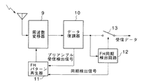
図2を参照して、受信部は周波数変移器9、データ復調器10、FHパターン再生器11、FH同期検出回路12、及び接続器13を備えており、周波数変移器9は、FHパターン再生器11から再生FHパターンに応じて送信側の搬送波周波数変移に追随して搬送波周波数をホッピング(変移)させる。FHパターン再生器11はFH同期信号検出回路12からの同期検出信号及びデータ復調器10からのプリアンブル受信検出信号に応じて次の▲1▼〜▲3▼の動作を行う。
【0012】
▲1▼デフォルト状態でサイクリック(f1→f2…→fn-1 →fn )に搬送波周波数を変化させる。
▲2▼プリアンブル受信状態で動作を一時固定する。
▲3▼同期検出信号に応じて送信側のFHパターンを再生する。
【0013】
図1及び図2を参照して、まず、タイミング発生器1からの切替制御信号によって切換器5はプリアンブル送信回路2とデータ変調器6とを接続する。そして、タイミング発生器1はプリアンブル送信回路2を動作させて、プリアンブル送信回路2からプリアンブル信号を送出させる。プリアンブル信号は切換器5を介してデータ変調器6に与えられ、ここでデータ変調されてプリアンブル変調信号となって、周波数変移器7に送られる。この時点では、タイミング発生器1からタイミング信号(動作信号)はFHパターン発生器8に与えられておらず、この結果、周波数変移器7は搬送波周波数を変移させず、所定の搬送波周波数でプリアンブル変調信号を送出することになる。つまり、図3に示すように、プリアンブル送出期間においては、周波数変移器7は搬送波周波数fkでプリアンブル変調信号を送信プリアンブル信号として送出している。
【0014】
受信側において、プリアンブルが受信できていない状態では、同期検出信号及びプリアンブル受信検出信号ともにFHパターン再生器11に与えられていないから、FHパターン再生器11はデフォルト状態であり、前述のように、搬送波パターンをサイクリックに変化させている。この結果、周波数変移器9は搬送波周波数をスキャンすることになる。つまり、図4に示すプリアンブル受信スキャン期間において、周波数変移器9は搬送波周波数をスキャンしている。
【0015】
搬送波周波数のスキャンによって、送信プリアンブル信号が周波数変移器9によって受信され、データ復調器10によってプリアンブル信号が検出されることになる。プリアンブル信号を検出すると、データ復調器10はプリアンブル受信検出信号をFHパターン再生器11に送出する。これによって、FHパターン再生器11は動作が固定される。この結果、周波数変移器9はFHパターン再生器11で指示される搬送波周波数で動作する。つまり、図4に示すプリアンブル捕捉期間において、周波数変移器9はFHパターン再生器11で指示される搬送波周波数(fk)で動作する。
【0016】
図1に示す送信部では、予め定められた時間が経過すると、タイミング発生器1では切換器5を切替制御してFH同期信号発生回路3とデータ変調器6とを接続する。そして、タイミング発生器1はFH同期信号発生回路3を動作させて、FH同期信号を送出させる。このFH同期信号は切換器5を介してデータ変調器6に与えられ、ここでデータ変調されてFH同期変調信号となって、周波数変移器7に送られる。周波数変移器7は所定の搬送波周波数でFH同期変調信号を送出する。つまり、図3に示すように、周波数変移器7は搬送波周波数fkでFH同期変調信号を送信FH同期信号として送出する。
【0017】
FH同期信号が送出されると、タイミング発生回路1は切換器5を切替制御して送信データ出力回路4とデータ変調器6とを接続するとともに送信データ出力回路4を起動させるとともにFHパターン発生器8を起動させる。FHパターン発生器8からFHパターンが周波数変移器7に与えられ、周波数変移器7はFHパターンに基づいて搬送波周波数変移を開始する。一方、送信データ出力回路4から送信データが切替器5を介してデータ変調器6に送られ、ここでデータ変調されてデータ変調信号として周波数変移器7に送られる。周波数変移器7では前述のようにFHパターンに応じて搬送波周波数を変移させて、データ変調信号を送信データ信号として送出する。つまり、図3に示すように、データ送出期間においては、周波数変移器7は搬送波周波数を変移させて、データ変調信号を送信データ信号として送出している。
【0018】
受信部では、周波数変移器9が搬送波周波数(fk)で動作している結果、送信FH同期信号が周波数変移器9によって受信され、データ復調器10でFH同期信号とされる。そして、FH同期検出回路12によってFH同期信号が検出されると、FH同期検出回路12は同期検出信号をFHパターン再生器11に与える。前述のように、FHパターン再生器11は同期検出信号に応じて送信側FHパターンを再生FHパターンとして再生し、この再生FHパターンを周波数変移器9に与える。周波数変移器9は再生FHパターンに応じて搬送波周波数を変移させて、送信側の搬送波周波数変移に追随することになる。これによって、送信データ信号が周波数変移器9で受信され、データ復調器10で復調されてデータ信号となる。
【0019】
FH同期検出回路12はFH同期信号を検出すると、FH同期が確立したと判断して、接続器13をオン状態として出力端子とデータ復調器19とを接続する。これによって、データ信号は受信データとして出力される。つまり、図4に示すデータ受信期間においては、周波数変移器9はFHパターン再生器11からの再生FHパターン(送信側FHパターン)に応じて搬送波周波数を変移させてFH同期を確立することになる。
【0020】
【発明の効果】
以上説明したように、本発明では予め定められた搬送波周波数で送信側からプリアンブル及びFH同期信号の送出を行って、FH同期が確立された後、搬送波周波数変移(周波数ホッピング)を行うようにしたから、受信側においては、プリアンブルの受信及びFH同期信号の受信を短時間で行うことができ、その結果、周波数変移速度が低速であってもFH同期確立を迅速かつ容易に行うことができるという効果がある。
【0021】
さらに、本発明では、送信データを送信する前に、FH同期を確立するようにしたから、初期の送信データが損なわれることがなく、そして、送信データをメモリ等にも格納する必要がないから即時性に欠けることなく通信を行うことができるという効果もある。
【図面の簡単な説明】
【図1】本発明による周波数ホッピング通信システムに用いられる送信部の一例を示すブロック図である。
【図2】本発明による周波数ホッピング通信システムに用いられる受信部の一例を示すブロック図である。
【図3】図1に示す送信部の動作を説明するための図である。
【図4】図2に示す受信部の動作を説明するための図である。
【符号の説明】
1 タイミング発生器
2 プリアンブル送信回路
3 FH同期信号発生回路
4 送信データ出力回路
5 切換器
6 データ変調器
7 周波数変移器
8 FHパターン発生器
9 周波数変移器
10 データ復調器
11 FHパターン再生器
12 FH同期検出回路
13 接続器[0001]
BACKGROUND OF THE INVENTION
The present invention relates to a communication system using a frequency hopping (FH) method, and more particularly to a communication system using a low-speed FH method. The present invention relates to a method for transmitting data communication while changing the communication frequency at a low speed.
[0002]
[Prior art]
In general, in a communication system using a low-speed FH system, transmission is performed by switching the carrier frequency at a speed slower than the bit speed of the information signal. That is, a plurality of bits are transmitted by one carrier wave. In such a communication system, on the transmission side, the communication frequency (carrier frequency) is changed (hopped) at a predetermined period, a change pattern is generated, and data is transmitted using this change pattern (hopping pattern). . On the other hand, the reception side is in a standby state at a predetermined carrier frequency, and when the transmission side carrier frequency matches the standby carrier frequency, the transition pattern is captured and FH synchronization is established, and then data reception is performed. ing.
[0003]
[Problems to be solved by the invention]
By the way, the conventional low-speed FH system has a problem that it takes time to capture the shift pattern and establish the FH synchronization because the carrier frequency shift speed is lower than the transmission speed.
[0004]
In addition, as described above, in the conventional low-speed FH method, since it takes time to establish the FH synchronization by capturing the shift pattern on the receiving side, the initial transmission data may be damaged. In order to prevent malfunctions, transmission data must be stored in storage means such as a memory until FH synchronization is established, and there is a problem of lack of immediacy.
[0005]
An object of the present invention is to provide an FH communication system capable of establishing FH synchronization in a short time.
[0006]
Another object of the present invention is to provide an FH communication system capable of performing immediate communication without damaging initial transmission data.
[0007]
[Means for Solving the Problems]
According to the present invention, a receiving unit and a transmitting unit are provided, a transmission data signal is transmitted from the transmitting unit to the receiving unit by frequency hopping, and the transmitting data signal is received as a received data signal by the receiving unit. in frequency hopping communication system, the to the transmitter, the data signal after the first delivery the second period frequency hopping synchronization signal in the delivery a second period following the period of the first preamble signal in the period And transmitting the preamble signal and the frequency hopping synchronization signal as a transmission preamble signal and a transmission frequency hopping synchronization signal, respectively, at a predetermined carrier frequency in the first and second periods. The transmission carrier frequency is shifted based on a predetermined frequency hopping pattern. Serial data signal is provided with the second means for transmitting as said transmission data signal, the receiver, the transmit preamble signal to the carrier frequency predetermined by changing the carrier frequency as the received carrier frequency And detecting the preamble signal, and when the preamble signal is detected, the received carrier frequency is fixed to the predetermined carrier frequency and the frequency hopping synchronization signal is detected in advance. And a fourth means for reproducing the determined frequency hopping pattern as a reproduction frequency hopping pattern, wherein the third means shifts the reception carrier frequency in accordance with the reproduction frequency hopping pattern to change the transmission data signal. frequency hopping, characterized in that it received as the received data signal Communication system is obtained.
[0008]
DETAILED DESCRIPTION OF THE INVENTION
The present invention will be described below with reference to the drawings.
[0009]
The communication system according to the present invention includes a transmission unit shown in FIG. 1 and a reception unit shown in FIG.
[0010]
First, referring to FIG. 1, the transmission unit includes a
[0011]
Referring to FIG. 2, the receiving unit includes a frequency shifter 9, a
[0012]
▲ 1 ▼ cyclic in the default state (f1 → f2 ... → f n -1 → f n) in order to change the carrier frequency.
(2) The operation is temporarily fixed in the preamble reception state.
{Circle around (3)} The FH pattern on the transmission side is reproduced according to the synchronization detection signal.
[0013]
Referring to FIGS. 1 and 2, first,
[0014]
On the receiving side, when the preamble is not received, neither the synchronization detection signal nor the preamble reception detection signal is supplied to the FH pattern regenerator 11, so the FH pattern regenerator 11 is in the default state. The carrier pattern is cyclically changed. As a result, the frequency shifter 9 scans the carrier frequency. That is, in the preamble reception scan period shown in FIG. 4, the frequency shifter 9 scans the carrier frequency.
[0015]
By transmitting the carrier frequency, the transmission preamble signal is received by the frequency shifter 9, and the preamble signal is detected by the
[0016]
In the transmission unit shown in FIG. 1, when a predetermined time elapses, the
[0017]
When the FH synchronization signal is transmitted, the
[0018]
In the reception unit, as a result of the frequency shifter 9 operating at the carrier frequency (fk), the transmission FH synchronization signal is received by the frequency shifter 9 and is converted into an FH synchronization signal by the
[0019]
When the FH
[0020]
【The invention's effect】
As described above, in the present invention, the preamble and FH synchronization signal are transmitted from the transmission side at a predetermined carrier frequency, and after the FH synchronization is established, the carrier frequency shift (frequency hopping) is performed. Therefore, the reception side can receive the preamble and the FH synchronization signal in a short time, and as a result, the FH synchronization can be established quickly and easily even if the frequency shift speed is low. effective.
[0021]
Furthermore, in the present invention, since FH synchronization is established before transmitting transmission data, the initial transmission data is not lost, and it is not necessary to store the transmission data in a memory or the like. There is also an effect that communication can be performed without lack of immediacy.
[Brief description of the drawings]
FIG. 1 is a block diagram illustrating an example of a transmission unit used in a frequency hopping communication system according to the present invention.
FIG. 2 is a block diagram showing an example of a receiving unit used in the frequency hopping communication system according to the present invention.
3 is a diagram for explaining an operation of a transmission unit illustrated in FIG. 1; FIG.
4 is a diagram for explaining an operation of a reception unit illustrated in FIG. 2;
[Explanation of symbols]
DESCRIPTION OF
Claims (5)
前記受信部には、前記搬送波周波数を変化させて前記予め定められた搬送波周波数を受信搬送波周波数として前記送信プリアンブル信号を受信して前記プリアンブル信号を検出する第3の手段と、前記プリアンブル信号が検出されると前記受信搬送波周波数を前記予め定められた搬送波周波数に固定し前記周波数ホッピング同期信号を検出した際前記予め定められた周波数ホッピングパターンを再生周波数ホッピングパターンとして再生する第4の手段が備えられ、前記第3の手段は前記再生周波数ホッピングパターンに応じて前記受信搬送波周波数を変移させて前記送信データ信号を前記受信データ信号として受信するようにしたことを特徴とする周波数ホッピング通信システム。In a frequency hopping communication system comprising a receiving unit and a transmitting unit, transmitting a transmission data signal from the transmitting unit to the receiving unit by frequency hopping, and receiving the transmission data signal as a received data signal in the receiving unit, wherein the transmission unit, first sending a data signal after sending the frequency hopping synchronization signal in sending the preamble signal a second period following the period of the first said second period in the first period And a predetermined frequency hopping after transmitting the preamble signal and the frequency hopping synchronization signal as a transmission preamble signal and a transmission frequency hopping synchronization signal, respectively, at a predetermined carrier frequency in the first and second periods. the data signal by displacing the transmission carrier frequency based on the pattern Serial is provided with second means for transmitting a transmission data signal,
In the receiving unit, a third means for detecting the preamble signal by receiving the transmission preamble signal using the predetermined carrier frequency as the reception carrier frequency by changing the carrier frequency, and detecting the preamble signal Then, a fourth means is provided for reproducing the predetermined frequency hopping pattern as a reproduction frequency hopping pattern when the received carrier frequency is fixed to the predetermined carrier frequency and the frequency hopping synchronization signal is detected. The frequency hopping communication system is characterized in that the third means shifts the reception carrier frequency in accordance with the reproduction frequency hopping pattern and receives the transmission data signal as the reception data signal .
Priority Applications (1)
| Application Number | Priority Date | Filing Date | Title |
|---|---|---|---|
| JP08455698A JP3949264B2 (en) | 1998-03-30 | 1998-03-30 | Frequency hopping communication system |
Applications Claiming Priority (1)
| Application Number | Priority Date | Filing Date | Title |
|---|---|---|---|
| JP08455698A JP3949264B2 (en) | 1998-03-30 | 1998-03-30 | Frequency hopping communication system |
Publications (2)
| Publication Number | Publication Date |
|---|---|
| JPH11284547A JPH11284547A (en) | 1999-10-15 |
| JP3949264B2 true JP3949264B2 (en) | 2007-07-25 |
Family
ID=13833929
Family Applications (1)
| Application Number | Title | Priority Date | Filing Date |
|---|---|---|---|
| JP08455698A Expired - Lifetime JP3949264B2 (en) | 1998-03-30 | 1998-03-30 | Frequency hopping communication system |
Country Status (1)
| Country | Link |
|---|---|
| JP (1) | JP3949264B2 (en) |
Families Citing this family (3)
| Publication number | Priority date | Publication date | Assignee | Title |
|---|---|---|---|---|
| DE60205137T2 (en) | 2002-01-03 | 2006-06-14 | Vkr Holding As Soeborg | METHOD AND SYSTEM FOR TRANSMITTING SIGNALS |
| DE102016220882A1 (en) | 2016-10-24 | 2018-04-26 | Fraunhofer-Gesellschaft zur Förderung der angewandten Forschung e.V. | Optimized hopping patterns for different sensor nodes and variable data lengths based on the telegram splitting transmission method |
| DE102016220883A1 (en) * | 2016-10-24 | 2018-04-26 | Fraunhofer-Gesellschaft zur Förderung der angewandten Forschung e.V. | Optimized combination of preamble and data fields for sensor networks with low power consumption based on the telegram splitting method |
-
1998
- 1998-03-30 JP JP08455698A patent/JP3949264B2/en not_active Expired - Lifetime
Also Published As
| Publication number | Publication date |
|---|---|
| JPH11284547A (en) | 1999-10-15 |
Similar Documents
| Publication | Publication Date | Title |
|---|---|---|
| US4635274A (en) | Bidirectional digital signal communication system | |
| JP3949264B2 (en) | Frequency hopping communication system | |
| US4225888A (en) | High efficiency facsimile transmission system | |
| JP3896873B2 (en) | Variable communication system | |
| US6654406B1 (en) | Frequency hopping receiver capable of real-time demodulation and method thereof | |
| JPH09172391A (en) | Spread spectrum communication system | |
| JP2600609B2 (en) | Communication system and transmission device | |
| JPH0795189A (en) | Frame synchronization system for digital communication | |
| JP2517920B2 (en) | Address information transmission method | |
| JPH10271037A (en) | Spread spectrum radio communication equipment | |
| JPH0591006A (en) | Voice transmitter | |
| JP3286128B2 (en) | Code division multiplex communication method and apparatus | |
| JP2571123B2 (en) | Manchester M-sequence code modulator | |
| JPH07177057A (en) | Spread spectrum modulator and/or demodulator | |
| JPH0435332A (en) | Spread spectrum communication system | |
| JPH04252531A (en) | System and device for spread spectrum communication | |
| JP4288800B2 (en) | Wireless communication system and communication method thereof | |
| JP2571122B2 (en) | Manchester M-sequence code modulator | |
| EP1087546B1 (en) | Method and system for radio communication | |
| JP3432419B2 (en) | Spread spectrum communication system | |
| JP2778378B2 (en) | Communications system | |
| JPH08223082A (en) | Information communication equipment | |
| JP3190863B2 (en) | Line switching method for wireless devices | |
| JPH09181703A (en) | Multiplex communication equipment | |
| JPH05110538A (en) | Spread spectrum communication equipment |
Legal Events
| Date | Code | Title | Description |
|---|---|---|---|
| A521 | Written amendment |
Free format text: JAPANESE INTERMEDIATE CODE: A523 Effective date: 20050118 |
|
| A621 | Written request for application examination |
Free format text: JAPANESE INTERMEDIATE CODE: A621 Effective date: 20050118 |
|
| A977 | Report on retrieval |
Free format text: JAPANESE INTERMEDIATE CODE: A971007 Effective date: 20060731 |
|
| A131 | Notification of reasons for refusal |
Free format text: JAPANESE INTERMEDIATE CODE: A131 Effective date: 20060802 |
|
| A521 | Written amendment |
Free format text: JAPANESE INTERMEDIATE CODE: A523 Effective date: 20060912 |
|
| TRDD | Decision of grant or rejection written | ||
| A01 | Written decision to grant a patent or to grant a registration (utility model) |
Free format text: JAPANESE INTERMEDIATE CODE: A01 Effective date: 20070404 |
|
| A61 | First payment of annual fees (during grant procedure) |
Free format text: JAPANESE INTERMEDIATE CODE: A61 Effective date: 20070418 |
|
| R150 | Certificate of patent or registration of utility model |
Free format text: JAPANESE INTERMEDIATE CODE: R150 |
|
| FPAY | Renewal fee payment (event date is renewal date of database) |
Free format text: PAYMENT UNTIL: 20100427 Year of fee payment: 3 |
|
| FPAY | Renewal fee payment (event date is renewal date of database) |
Free format text: PAYMENT UNTIL: 20110427 Year of fee payment: 4 |
|
| FPAY | Renewal fee payment (event date is renewal date of database) |
Free format text: PAYMENT UNTIL: 20120427 Year of fee payment: 5 |
|
| FPAY | Renewal fee payment (event date is renewal date of database) |
Free format text: PAYMENT UNTIL: 20130427 Year of fee payment: 6 |
|
| FPAY | Renewal fee payment (event date is renewal date of database) |
Free format text: PAYMENT UNTIL: 20140427 Year of fee payment: 7 |
|
| EXPY | Cancellation because of completion of term |