JP3949164B2 - A feedback method for controlling nonlinear processes. - Google Patents
A feedback method for controlling nonlinear processes. Download PDFInfo
- Publication number
- JP3949164B2 JP3949164B2 JP53277796A JP53277796A JP3949164B2 JP 3949164 B2 JP3949164 B2 JP 3949164B2 JP 53277796 A JP53277796 A JP 53277796A JP 53277796 A JP53277796 A JP 53277796A JP 3949164 B2 JP3949164 B2 JP 3949164B2
- Authority
- JP
- Japan
- Prior art keywords
- control
- values
- amount
- variable
- plant
- Prior art date
- Legal status (The legal status is an assumption and is not a legal conclusion. Google has not performed a legal analysis and makes no representation as to the accuracy of the status listed.)
- Expired - Lifetime
Links
Images


Classifications
-
- G—PHYSICS
- G05—CONTROLLING; REGULATING
- G05B—CONTROL OR REGULATING SYSTEMS IN GENERAL; FUNCTIONAL ELEMENTS OF SUCH SYSTEMS; MONITORING OR TESTING ARRANGEMENTS FOR SUCH SYSTEMS OR ELEMENTS
- G05B13/00—Adaptive control systems, i.e. systems automatically adjusting themselves to have a performance which is optimum according to some preassigned criterion
- G05B13/02—Adaptive control systems, i.e. systems automatically adjusting themselves to have a performance which is optimum according to some preassigned criterion electric
- G05B13/04—Adaptive control systems, i.e. systems automatically adjusting themselves to have a performance which is optimum according to some preassigned criterion electric involving the use of models or simulators
- G05B13/048—Adaptive control systems, i.e. systems automatically adjusting themselves to have a performance which is optimum according to some preassigned criterion electric involving the use of models or simulators using a predictor
-
- C—CHEMISTRY; METALLURGY
- C08—ORGANIC MACROMOLECULAR COMPOUNDS; THEIR PREPARATION OR CHEMICAL WORKING-UP; COMPOSITIONS BASED THEREON
- C08F—MACROMOLECULAR COMPOUNDS OBTAINED BY REACTIONS ONLY INVOLVING CARBON-TO-CARBON UNSATURATED BONDS
- C08F2400/00—Characteristics for processes of polymerization
- C08F2400/02—Control or adjustment of polymerization parameters
Landscapes
- Engineering & Computer Science (AREA)
- General Physics & Mathematics (AREA)
- Automation & Control Theory (AREA)
- Computer Vision & Pattern Recognition (AREA)
- Evolutionary Computation (AREA)
- Medical Informatics (AREA)
- Software Systems (AREA)
- Artificial Intelligence (AREA)
- Health & Medical Sciences (AREA)
- Physics & Mathematics (AREA)
- Feedback Control In General (AREA)
- Crystals, And After-Treatments Of Crystals (AREA)
- Apparatuses And Processes For Manufacturing Resistors (AREA)
- Electrotherapy Devices (AREA)
- General Factory Administration (AREA)
- Separation By Low-Temperature Treatments (AREA)
Abstract
Description
発明の分野
本発明は、プロセス制御システム、より詳細には、プラント操作量とプラント制御量との間に非線形の関係が存在する、モデルに基づくフィードバック制御システムに関する。
技術背景
プレット(Prett)等の「動的マトリックス制御法」と題する米国特許第4,349,869号は、プラント環境において、一連の相互依存プロセスの操作を制御し最適化するための方法と装置について記載している。制御動作を成し遂げるために、プラントへの入力変数は、測定された摂動にさらされ、出力における動的効果が記録され、オンライン動作の間、プロセスの将来の応答の予測を可能にする。制御法を実行するために、プレット等は、初期試験段階の間に見出される値の一覧表を構築する。種々の入力及びその結果得られる出力が、その表に組み込まれ、その表は、その後、それに続くプラント操作の間、主たる基準点としての役割を果たす。
プレット等の手続きは、特に、線形システム操作又は線形と擬制され得る操作の制御に適合する。しかしながら、非線形プラント操作に直面すると、プレット等の手続きは、特に、多くの制御量と操作量とがある場合には、適切に機能しない。制御量は、1以上の操作量、例えばプラントへの入力、の変化の影響を受けるプラント出力である。
動的マトリックス制御法の重合方法への適用は、ピーターソン(Peterson)等により、「非線形DMCアルゴリズム及び半バッチ式重合反応器へのその応用」、化学工学(Chem. Eng. Science)、第47巻、第4号、737−753頁(1992年)中に記載されている。ピーターソン等は、解を導くために、非線形制御装置及び数値アルゴリズムを使用するが、彼らの手続きは、制御解を得るにあたり、入力状態コストの最小化を試みていない。ブラウン(Brown)等は、「制約された非線形多変数制御アルゴリズム」、トランス・アイ・ケムイー(Trans I ChemE)、第68巻(A)、1990年9月、464−476頁に、好ましい出力値の具体的なレベル(その範囲内では、制御動作が阻害される)を含む非線形制御装置を記載している。しかしながら、ブラウン等は、出力制御を達成するだけではなく、入力値が最小コストを達成するための試験をしていない。
特許の先行技術には、制御量と操作量とを関連付けるために線形及び非線形の両者の式を用いる、モデルに基づく制御システムの使用に関する多くの教示がある。アクセルビー(Axelby)等の米国特許第4,663,703号は、将来の出力をシミュレートし且つ予測するためにサブシステムのインパルス・モデルを用いる、基準予測モデル制御装置を記載している。そのシステムは、動的システムを、その動特性が変化している時でさえも、一定不変の特性を有しているように見えるようにするよう調整されている、調整可能なゲイン・フィードバックと制御のループとを含む。
ビューフォード(Beauford)等の米国特許第5,260,865号は、プロセス蒸気/蒸留物流速を計算するために非線形モデルを用いる、蒸留法のための非線形のモデルに基づく制御システムを記載している。サンチェズ(Sanchez)(4,358,822)は、プロセス出力を将来の一定時間に所望の値にするために、モデルがプロセスに適用される制御ベクトルを決定する、適応−予測制御システムを記載している。モデルのパラメータは、出力ベクトルを実際のプロセス・ベクトルに近づけるために、リアル・タイム基準で最新のものとされている。サンナー(Sanner)等の米国特許第5,268,834号では、制御用プラント・モデルを構成するために、ニューラル・ネットワークを用いている。
モデルに基づく制御システムのプラント操作への拡張は、プラント操作が動的非線形プロセスを含み、且つ、多くの操作量及び制御量を含む場合には、簡単な問題ではない。最近まで、程よい大きさで且つ程よい値段のプロセス制御コンピュータは、そのような動的プラント・プロセスのモデル化の結果として生じる多くの連立方程式の解法を扱う処理能力を欠いていた。
基準合成技術は、非線形の制御の問題(例えば、pH制御の問題)への適用のために開発された。基準システム合成技術においては、非線形プラント・システムを、基準軌道に追従させ、一旦プラント遅延が終了したら、一次又は二次軌道に従って、設定値に到達させるのが望ましい。バーツシアク(Bartusiak)等は、「基準システム合成によって設計された非線形フィード・フォワード/フィードバック制御構造」、化学工学(Chem. Eng. Science)、第44巻、第9号、1837−1851頁(1989年)に、高度に非線形のプラント操作に適用され得る制御プロセスを記載している。基本的に、バーツシアク等は、一組の微分方程式によって制御されるプラントを説明している。閉ループ制御システムの所望の動作は、設計によって非線形となり得る一組の積分/微分方程式として表される。所望の動作は、基準システムと呼称される。
バーツシアク等は、システムが可能な限りほぼ基準システムのように動作するように、操作量を調節することにより、所望の閉ループ動作結果に到達する。操作量動作は、開ループ・システムと所望の閉ループ・システムとを同一にする、あるいは一般的にはその間の相違を最小化することによって、決定される。プラントの所望の動作は、その後、定められる。制御量は、制御量が設定値に到達する際の速度を制御する同調パラメータと共に、規定される。より詳細には、所望のプラント出力パラメータが設定され、制御システムが制御段階において所望の出力パラメータに到達する際の速度が、同調パラメータによって指示される。つまり、制御機能は、操作量コスト関数に関係なく、出力が特定のパラメータ値に到達するように運転される。その結果は、操作量コストにおける変化量を考慮していないので、効果的なプラント操作制御のみならず、コストの最小化をも可能にする。
従って、本発明の目的は、非線形プロセスを制御するための改良された方法であって、同調パラメータの制御量への適用を可能にする方法を提供することにある。
本発明の他の目的は、非線形プロセスを制御するための改良された方法であって、その制御方法が、操作量入力コストの最小化を可能にし、同時に所望の制御量を達成する方法を提供することにある。
発明の概要
システムは、操作量(例えば入力状態)及び制御量(例えば出力状態)を含むプラント・プロセスを制御する。当該システムは、制御量の測度を提供するためのセンサ回路と、少なくとも一つの制御量の補正時間定数及び上下限を格納するためのメモリを含む。上下限は、一群の値であって、その中にはその一つの制御量が受入れ可能であると考えられる一群の値の範囲によって、隔てられている。プロセッサは、操作量のコストを制御量に関係付け、且つ、解においては、その一つの制御量の予測値を更に提供するプロセス・モデルを示す、データを含む。プロセッサ内での論理は、一群の値の範囲の外側にあるその一つの制御量の測定値関数に応答し、その一つの制御量の予測値を受入れ可能な一群の値の範囲内に復帰させるための最小コスト操作量を決定する。プラント内での制御手段は、操作量(及び入力状態)をプロセッサからの信号に従って変えるように作用する。
【図面の簡単な説明】
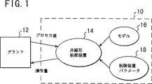
図1は、本発明を含むシステムのブロック図である。
図2は、本発明で用いられる制御機能の概要である。
図3及び4は、発明の動作を理解するのに有用なフロー図である。
発明の詳細な説明
以後、本発明の説明において、次の用語を使用する。
プロセス・モデル:プロセス・モデルは、プラント・システム操作を定め、且つ、代数及び微分方程式の形式において、連続時間領域内において公式化される。
操作量の離散化:操作移動は、離散時間変数である。プロセス・モデル内での使用のための離散操作移動量を提供するために、零次保持関数を使用する。
基準軌道:基準軌道は、制御量の応答速度としての、制御装置性能の基準を与える。
目標関数:目標関数は、最適制御性能を定める。目標関数は、制御設定値の妨害に対する損失補償と経済的コスト(利益)関数とを包含する。
操作量限界:操作量限界は、範囲限界、設定値限界、非ワインド・アップ条件等の第二の制御装置限界又は状態を反映するように設定される。
フィードバック:フィードバックは、プロセス測定とモデル予測との間の誤差を示すバイアス値として、基準軌道中に組み込まれる。
状態推定:プロセス・モデル状態及び出力の予測は、操作量とフィード・フォワード量からの最新の値と、前回の制御装置の走査時間を通じて導かれた予測に基づき、動的モデルの積分により、各制御装置の走査の際に提供される。
初期化:制御装置出力の初期化は、各走査の際の最新の操作量の値の読取りと、その値に対する増分としての制御装置移動を与えることによって提供される。制御装置プログラムが(閉ループ又は開ループで)実行されているとき、モデル状態及び出力は、前回の制御装置の走査の間に予測された値において、初期化される。プログラムが初めてターン・オンされるときは、モデル状態及び出力は、最新の操作値とフィード・フォワード値のための定常状態モデルを解くことによって初期化される。
図1を参照すると、デジタル型コンピューターに基づく制御システムは、プラント12内で生じているプロセスを監視している。プロセス値は、デジタル型制御システム10内に存在する非線形制御装置機能14に供給される。プロセス・モデル16は、デジタル型制御システム10内に内蔵されており、非線形制御装置14のための基準システムを提供する一連の非線形方程式を表す。複数の制御パラメータ18は、非線形制御装置14によって得られた制御値の制約を提供する。プロセス値測定を、(制御パラメータ18を用いて)解モデル16を通して得られた予測値と比較することにより、補正値が導かれ、且つ、それは、プラント12への制御入力として使用される。
図2においては、非線形制御装置14は、システム操作量、独立変数及びバイアス値における変化のプロセス状態の速度変化を定める、動的プロセス・モデル16を含む。非線形制御装置14は、更に、閉ループ・プロセス応答特性を定める、1以上の同調値を含む。より詳細には、各プロセス応答特性は、操作量の変化に応じて、制御量によって追従される軌道を定める。最適化機能19は、測定値とプロセス・モデル16から与えられた予測値との間に生じた差が与えられて、所望の応答同調軌道を達成する最小化操作量コストを決定する。
以降において、非線形制御装置14が、プラント12からの1以上の制御量(例えば出力)のための限界境界を設定することが理解されるであろう。一旦、一つの制御量の上下限が設定されると、非線形制御装置14は、制御量と、その制御量の限界の少なくとも一つに関係しての所望の移動速度との間の、変化の測定された速度を比較する制御手続きを行う。仮に制御量が上下限内であるならば、制御動作は何も行われない。仮に制御変数が範囲外であるならば、変化の測定された動的速度と変化のモデル動的速度とを比較すると、変化値の誤差速度が誘導され得る。変化値のその誤差速度は、その後、目標関数によって使用され、それは、一組の操作量(それは、制御量を上下限範囲内へ復帰させるための最小コストを表す)の決定を可能とする。制御量の値の受入れ可能な範囲を定めるために上下限を利用することにより、いずれの組み合わせが制御量を限度内へ復帰させ、同時に操作量コストを最小化するかを決定するために、種々の操作量コストが試験され得る。
図3及び4を参照して、非線形制御装置14の動作の説明を行う。非線形制御装置14は、プラント12に結合された汎用コンピュータにおいて実行される。非線形制御装置14は、特定の頻度又は走査速度、例えば1分当たり1回、で作動し、それにより、制御量が監視され、操作量は、制御動作を実行するため、各々の移動量を得るように計算される。
デジタル型制御システム10中にプラント・データを読み込む(ボックス30)ことにより、手続きが始まる。それらのデータは、制御量、操作量、及び付加的又はフィード・フォワード変数の最新の値を含む。プラント測定値は、その現場の計器によって、又はオフライン研究室分析を通じて、供給される。次に、各制御量の最新の測定値が、対応するモデル予測値と比較される。ブラント−モデル間の食い違いを示すバイアス値は、測定値と予測値との間の差として計算される(ボックス32)。
ボックス34に示されているように、次に、入力データが妥当であることが確認される(例えば、利用できない測定値や範囲外の値等の正常ではない条件は、棄てられる)。データ調整も行われ、それは、オペレータが特定した限界及びプラント制御システム状態値に基づく、フィルタリングや操作量の境界の設定を含む。
非線形制御装置14の動作の開始の際、コールド・スタート初期化が行われる(決定ボックス36参照)。独立変数のための値(操作又はフィード・フォワード)は、デジタル型制御システム10内に格納されているデータベースから読取られる(ボックス38)。初期化動作は、モデル状態と、温度、組成物及び生成物特性等のプラント状態を示すプラント出力とを計算する。モデルは、何らかの数理的形態であってよい。
これ以降においては、手続きの説明の目的で、状態−空間モデルを使用する。各状態は、“X”ベクター値によって定められ、プラント出力は、“y”ベクター値によって表される。独立変数は、次のように、値“u”によって表される:
O=F(x,u) (1)
y=H(x) (2)
プラント状態の値は、その後、非線形制御装置14の初期値として使用される(ボックス40及び42参照)。状態値は、その後、推定され、メモリに書き込まれる(ボックス44)。この時点で、非線形制御装置14は、プロセス制御アルゴリズムの動作を開始する(ボックス46)。
図4に示されているように、制御プロセスは、プラント制御システム・ハードウェアからプロセス・データを読取り(ボックス48)、プロセスの現在の状態を決定する。そのデータは、次の事項を含む:
各モデル状態の初期値、
予測されたプラント出力の初期値、
プラント−モデル間の誤差を示すバイアス値、
モデル・パラメータ、
独立変数の最新の測定値、
制御量のための設定値又は目標値、及び制約、
操作量の境界、
入力状態条件。
モデル状態及び予測されたプラント出力の値は、前回の制御装置の実行から得られた値であるか、あるいは、コールド・スタート初期化値からのものである。制御量(例えば、制御される出力)及び制約設定値は、オペレータによって入力される。設定値は、上限値及び下限値として入力される。これらの値の使用により、上下限値の範囲内の制御量値に到達するに際して、最小化コストを達成するための操作量(入力)の調節が可能となる。モデル・パラメータ値は、前もって決められている。独立変数の最新の測定値は、プラントの現場の計器又は研究室分析から導かれる。操作量の境界は、上記の如く、オペレータが特定した限界及びプラント制御システム状態値に基づく。
その後、制御装置動作モードが設定される(ボックス50)。一つの制御装置モードにより、モデル予測の計算が可能となり、制御信号が得られるようになり、その制御信号を別個にプラントに用いることが不要となる。これ以降において、デジタル型制御システムは、完全に動作モード(そのモードでは、操作量が、モデル計算及び測定されたシステム状態に従って、積極的に制御されることになっている)で設定されているとみなす。
入力データは、モデル−制御システムを用いた使用のための形態に変換され(ボックス52)、状態推定手続きが開始される(ボックス54)。各状態は、プラントの動的モデルを用いて推定される。下記方程式3及び4中に示された状態−空間モデルにおいて、状態は“x”値で表され、プラント出力は“y”変数で表され、独立変数は“u”で表される。
dx/dt=F(x,u) (3)
y=H(x) (4)
方程式3は、モデル状態の変化速度が、モデル状態それ自体及び独立変数の関数であることを示す。方程式4は、出力がモデル状態の関数であることを示す。モデル推定は、非線形制御装置14の前回の実行から現在までの方程式3及び4の積分によって得られる。好ましい計算方法は、方程式3及び4が時間部分に分割される直交の配置を包含し、そのために、微分方程式は、同じ時間部分において同時に解かれ得る。
非線形制御装置14によって行われる制御計算は、順次二次プログラミング技術を用いることによって行われる(ボックス56)。制御計算は、操作量の将来の移動(それは、将来に向けての時間にわたって、制御性能の仕様に最もよく釣り合う)を決定する。非線形制御装置14は、プラントのモデル、特定の制御装置性能を定める基準軌道、目標関数(下記する)及び操作量境界を利用する。操作量移動は、将来に向けての時間にわたって離散化される。
方程式3及び4中に示されたモデルが利用される。上記の如く、“u”変数は独立変数を表し、その部分集合は、操作量(即ち入力)である。全独立変数のための値は、各時間ステップkにおける離散操作量Ukの“零次保持関数”によって得られる。零次保持関数は、操作量の値がプログラム実行の間一定のままであると推定する。
基準軌道は、適用された制約に従って制御量を変えている際の、制御装置性能を特定する。下記基準軌道方程式5及び6は、制御量の変化速度間の関係と、制御量設定値と測定された制御量との間の誤差(又は差)を表す。
dyk/dt=(SPHk−(yk+b))/T+Vhpk−Vhnk (5)
dyk/dt=(SPLk−(yk+b))/T+Vlpk−Vlnk (6)
k=1〜K
Vlp>=0.0
Vln>=0.0
Vhp>=0.0
Vhn>=0.0
ここで:
SPH=制御量又は制約の上限;
SPL=制御量又は制約の下限;
y=予測された制御量;
b=予測と測定との誤差に関係するバイアス;
Vhp=測定された量のSPHからの正の差分;
Vhn=測定された量のSPHからの負の差分;
Vlnk=測定された量のSPLからの正の差分;
Vln=測定された量のSPLからの負の差分;
k=将来に向けての時間ステップ;
K=制御装置によって使用される時間における、将来に向けての時間ステップ数;
T=所望の被制御量の応答の閉ループ速度のための時間定数。
変数Vlp、Vhp、Vln及びVhnの各々を、これ以降において、“妨害”量と呼称する。各妨害量は、不等式を等式関係に変換させ、目標関数における重み関数の適用を通して、制約を優先させる。目標関数(即ち、制御動作によって満足させられる関係)は、次の式によって与えられる。
最小和(Wh*Vhpk+Wl*Vlnk)+C(x,u) (7)
ここで:
Wh,Wl=損失重量;
Vhpk,Vlnk=上記妨害量;
C(x,u)=コスト損失関数。
方程式7は、制御量の上限又は制御量の下限の妨害が生じた際に使用される、合計最小化関数を表す。方程式7は、事情に応じて、正の妨害値又は負の妨害値の強調(又は重点が置かれなくなる)を可能にする、重み係数を用いる。方程式7は、また、操作量uとモデル状態xの両者に依存するコスト関数である、一つの項(即ちC(x,u))をも包含する。
制御システムは、方程式7を解き、操作量に複数の変化が試みられるときに、各々の解に由来する合計の数値を出す。目的は、上限(SPH)及び下限(SPL)で定められた範囲内への、制御量yの復帰を達成することである。SPHとSPLは、制御量の受入れ可能な範囲を定める、ある範囲の値によって隔てられているから、操作量における多くの生じ得る変化は、いずれの組合せが、制御量の受入れ可能な範囲への復帰を達成しながら操作量の最小のコストをもたらすかを決定するために、計算され得る。(何らかの制御動作において、)操作量が、SPHとSPLとの間の範囲内にプラント出力を復帰させることができるとき、方程式7における初めの二つの記号のそれぞれは0とされ、関数の解は、操作量によって表されたコストに完全に関係付けられる。
方程式7の最適化された解は、下記方程式8及び9で表されるように、更なる操作量の境界に従属している。
ulb<uk<uhb (8)
ABS(uk−u(k−1)<dub (9)
ここで:
uhb=操作量の上の境界;
ulb=操作量の下の境界;
dub=時間ステップ間のuの変化における限界。
一旦、受入れ可能な解が得られると、出力(将来における各時間ステップのための操作量の値からなる)は、システム制約と照合される(ボックス58)。出力データが妥当であると想定して、その後、データがメモリに書き込まれ(ボックス60)、計算された操作値がプラントに送られ(ボックス62)、現場制御要素(例えばバルブ)を操作する。
前述の説明は、本発明の一実例にすぎないことが理解されるべきである。種々の代替例及び修飾態様が、本発明から外れることなく、当業者によって工夫され得る。従って、本発明は、付随する請求項の範囲内にある、すべての代替例、修飾態様及び変化態様を包含することが意図される。 FIELD OF THE INVENTION The present invention relates to a process control system, and more particularly to a model-based feedback control system in which a non-linear relationship exists between plant manipulated variables and plant controlled variables.
Technical background U.S. Pat. No. 4,349,869 entitled "Dynamic Matrix Control Method" such as Prett et al. Is intended to control and optimize the operation of a series of interdependent processes in a plant environment. The method and apparatus are described. In order to accomplish the control action, the input variables to the plant are exposed to the measured perturbations and the dynamic effects at the output are recorded, allowing prediction of the future response of the process during on-line operation. In order to implement the control method, Plett et al build a list of values found during the initial test phase. Various inputs and resulting outputs are incorporated into the table, which then serves as the main reference point during subsequent plant operations.
Procedures such as Plett are particularly suited for controlling linear system operations or operations that can be imitated as linear. However, in the face of nonlinear plant operation, procedures such as pellets do not function properly, especially when there are many control and operation variables. The controlled variable is a plant output that is affected by a change in one or more manipulated variables, for example, an input to the plant.
The application of the dynamic matrix control method to the polymerization method is described by Peterson et al., “Nonlinear DMC algorithm and its application to a semi-batch polymerization reactor”, Chemical Engineering (Chem. Eng. Science), 47th. Vol. 4, No. 4, pages 737-753 (1992). Peterson et al. Uses nonlinear controllers and numerical algorithms to derive solutions, but their procedures do not attempt to minimize input state costs in obtaining control solutions. Brown et al. In "Constrained Nonlinear Multivariable Control Algorithm", Trans I ChemE, Volume 68 (A), September 1990, pages 464-476, preferred output values. A non-linear control apparatus including a specific level (in which the control operation is inhibited) is described. However, Brown et al. Not only achieve output control, but have not tested the input value to achieve minimum cost.
The prior art in the patent has many teachings on the use of model-based control systems that use both linear and non-linear equations to correlate control quantities with manipulated variables. U.S. Pat. No. 4,663,703 to Axelby et al. Describes a reference predictive model controller that uses subsystem impulse models to simulate and predict future output. The system includes adjustable gain feedback that is tuned to make the dynamic system appear to have a constant characteristic even when its dynamic characteristics are changing. Control loop.
Beauford et al., US Pat. No. 5,260,865, describes a non-linear model based control system for a distillation process that uses a non-linear model to calculate process vapor / distillate flow rates. Yes. Sanchez (4, 358, 822) describes an adaptive-predictive control system in which the model determines the control vector applied to the process in order to bring the process output to a desired value at a fixed time in the future. ing. The model parameters are updated on a real-time basis to bring the output vector closer to the actual process vector. In US Pat. No. 5,268,834 to Sanner et al., A neural network is used to construct a control plant model.
The extension of a model-based control system to plant operation is not a simple problem when the plant operation includes a dynamic non-linear process and includes many manipulated variables and controlled variables. Until recently, reasonably sized and reasonably priced process control computers lacked the processing power to handle the solution of many simultaneous equations that resulted from modeling such dynamic plant processes.
Reference synthesis techniques have been developed for application to non-linear control problems (eg, pH control problems). In the reference system synthesis technique, it is desirable that the nonlinear plant system is made to follow the reference trajectory, and once the plant delay is completed, the set value is reached according to the primary or secondary trajectory. Bartusiak et al., “Nonlinear feed-forward / feedback control structures designed by reference system synthesis”, Chem. Eng. Science, Vol. 44, No. 9, pp. 1837-1851 (1989). ) Describes a control process that can be applied to highly nonlinear plant operations. Basically, Berthiak et al. Describe a plant controlled by a set of differential equations. The desired operation of the closed loop control system is represented as a set of integral / differential equations that can be non-linear by design. The desired action is referred to as the reference system.
Berthiak et al. Reaches the desired closed-loop operation result by adjusting the manipulated variable so that the system operates as much as possible in the reference system. The manipulated variable motion is determined by making the open loop system and the desired closed loop system the same, or generally minimizing the difference between them. The desired operation of the plant is then defined. The control amount is defined together with a tuning parameter that controls the speed at which the control amount reaches the set value. More specifically, the desired plant output parameter is set and the speed at which the control system reaches the desired output parameter in the control phase is indicated by the tuning parameter. That is, the control function is operated so that the output reaches a specific parameter value regardless of the operation amount cost function. As a result, since the amount of change in the operation amount cost is not taken into consideration, not only effective plant operation control but also cost minimization is possible.
Accordingly, it is an object of the present invention to provide an improved method for controlling a non-linear process that allows application of tuning parameters to controlled variables.
Another object of the present invention is an improved method for controlling a non-linear process, the control method providing a method for minimizing manipulated variable input costs and at the same time achieving a desired controlled variable. There is to do.
SUMMARY OF THE INVENTION The system controls a plant process that includes manipulated variables (e.g., input states) and controlled variables (e.g., output states). The system includes a sensor circuit for providing a measure of the controlled variable and a memory for storing at least one corrected time constant and upper and lower limits for the controlled variable. The upper and lower limits are a group of values that are separated by a range of groups of values that are considered acceptable for the one controlled variable. The processor includes data that relates the cost of the manipulated variable to the controlled variable and, in the solution, indicates a process model that further provides a predicted value for that single controlled variable. The logic within the processor is responsive to the measured value function of that single controlled variable outside the range of values of the group, and returns the predicted value of that single controlled variable to within the range of acceptable values. To determine the minimum cost operation amount. The control means in the plant acts to change the manipulated variable (and the input state) according to the signal from the processor.
[Brief description of the drawings]
FIG. 1 is a block diagram of a system including the present invention.
FIG. 2 is an outline of the control function used in the present invention.
3 and 4 are flow diagrams useful for understanding the operation of the invention.
DETAILED DESCRIPTION OF THE INVENTION Hereinafter, the following terms will be used in the description of the present invention.
Process model: The process model defines the plant system operation and is formulated in the continuous time domain in the form of algebra and differential equations.
Discretization of manipulated variable: Manipulated movement is a discrete time variable. A zero order hold function is used to provide a discrete amount of movement for use within the process model.
Reference trajectory: The reference trajectory gives a reference for the performance of the control device as the response speed of the controlled variable.
Target function: The target function defines the optimal control performance. The target function includes loss compensation for control setpoint disturbances and an economic cost (benefit) function.
Operating amount limit: The operating amount limit is set to reflect a second controller limit or condition, such as a range limit, setpoint limit, non-windup condition, etc.
Feedback: Feedback is incorporated into the reference trajectory as a bias value indicating the error between process measurement and model prediction.
State estimation: Process model state and output prediction is based on the latest values from the manipulated variable and feed forward amount, and the prediction derived through the previous controller scan time. Provided during controller scan.
Initialization: Initialization of the controller output is provided by reading the latest manipulated variable value during each scan and giving the controller movement as an increment to that value. When the controller program is running (closed loop or open loop), the model state and output are initialized at the values predicted during the previous controller scan. When the program is turned on for the first time, the model states and outputs are initialized by solving a steady state model for the latest operating and feed forward values.
Referring to FIG. 1, a digital computer based control system monitors the processes occurring within the
In FIG. 2, the
In the following, it will be understood that the
The operation of the
The procedure begins by loading plant data into the digital control system 10 (box 30). These data include controlled variables, manipulated variables, and the latest values of additional or feed forward variables. Plant measurements are supplied by on-site instrumentation or through offline laboratory analysis. Next, the latest measured value of each controlled variable is compared with the corresponding model predicted value. A bias value indicative of the Blunt-model discrepancy is calculated as the difference between the measured and predicted values (box 32).
As shown in
At the start of the operation of the
In the following, the state-space model is used for the purpose of explaining the procedure. Each state is defined by an “X” vector value, and the plant output is represented by an “y” vector value. The independent variable is represented by the value “u” as follows:
O = F (x, u) (1)
y = H (x) (2)
The plant state value is then used as the initial value for the nonlinear controller 14 (see
As shown in FIG. 4, the control process reads process data from the plant control system hardware (box 48) to determine the current state of the process. The data includes the following:
Initial value of each model state,
The initial value of the predicted plant output,
A bias value indicating the error between the plant and the model,
Model parameters,
The latest measured value of the independent variable,
Set value or target value for the controlled variable, and constraints;
Boundary of manipulated variable,
Input state condition.
The model state and predicted plant output values are those obtained from previous controller runs or from cold start initialization values. Control amounts (eg, controlled output) and constraint settings are entered by the operator. The set value is input as an upper limit value and a lower limit value. By using these values, it is possible to adjust the operation amount (input) for achieving the minimization cost when the control amount value within the range of the upper and lower limit values is reached. Model parameter values are predetermined. The latest measured values of the independent variables are derived from on-site instrumentation or laboratory analysis of the plant. As described above, the boundary of the operation amount is based on the limit specified by the operator and the state value of the plant control system.
Thereafter, the controller operating mode is set (box 50). One controller mode makes it possible to calculate model predictions and obtain a control signal, which makes it unnecessary to use the control signal separately for the plant. From this point on, the digital control system is set in a fully operational mode (in which mode the manipulated variable is to be actively controlled according to the model calculation and the measured system state). It is considered.
The input data is converted to a form for use with the model-control system (box 52) and the state estimation procedure is initiated (box 54). Each state is estimated using a dynamic model of the plant. In the state-space model shown in equations 3 and 4 below, the state is represented by an “x” value, the plant output is represented by a “y” variable, and the independent variable is represented by “u”.
dx / dt = F (x, u) (3)
y = H (x) (4)
Equation 3 shows that the rate of change of the model state is a function of the model state itself and the independent variables. Equation 4 shows that the output is a function of the model state. The model estimate is obtained by the integration of equations 3 and 4 from the previous execution of the
The control calculations performed by the
The model shown in equations 3 and 4 is used. As described above, the “u” variable represents an independent variable, and its subset is the manipulated variable (ie, input). The values for all independent variables are obtained by a “zero order holding function” of the discrete manipulated variable U k at each time step k. The zero order hold function estimates that the manipulated value remains constant during program execution.
The reference trajectory specifies the performance of the control device when the control amount is changed according to the applied constraints. The following reference trajectory equations 5 and 6 represent the relationship between the change rate of the control amount and the error (or difference) between the control amount set value and the measured control amount.
dy k / dt = (SPH k − (y k + b)) / T + Vhp k −Vhn k (5)
dy k / dt = (SPL k − (y k + b)) / T + Vlp k −Vln k (6)
k = 1 to K
Vlp> = 0.0
Vln> = 0.0
Vhp> = 0.0
Vhn> = 0.0
here:
SPH = control amount or upper limit of constraints;
SPL = lower limit of control amount or constraint;
y = predicted control amount;
b = bias related to the error between prediction and measurement;
Vhp = positive difference from measured amount of SPH;
Vhn = negative difference from measured amount of SPH;
Vln k = positive difference from measured amount of SPL;
Vln = negative difference from measured amount of SPL;
k = time step for the future;
K = number of time steps for the future in the time used by the controller;
T = time constant for the closed loop speed of the desired controlled quantity response.
Each of the variables Vlp, Vhp, Vln, and Vhn is hereinafter referred to as a “disturbance” amount. Each amount of interference transforms the inequality into an equality relationship and gives priority to constraints through the application of a weight function in the target function. The target function (ie, the relationship satisfied by the control action) is given by
The minimum sum (Wh * Vhp k + Wl * Vln k) + C (x, u) (7)
here:
Wh, Wl = loss weight;
Vhp k , Vln k = the above disturbance amount;
C (x, u) = cost loss function.
Equation 7 represents the total minimization function used when the upper limit of the control amount or the lower limit of the control amount occurs. Equation 7 uses a weighting factor that allows emphasis (or no more emphasis) on positive or negative disturbance values depending on the circumstances. Equation 7 also includes a single term (ie, C (x, u)) that is a cost function that depends on both the manipulated variable u and the model state x.
The control system solves Equation 7 and gives a total value derived from each solution when multiple changes are attempted in the manipulated variable. The purpose is to achieve the return of the controlled variable y within the range defined by the upper limit (SPH) and the lower limit (SPL). Since SPH and SPL are separated by a certain range of values that define the acceptable range of the controlled variable, many possible changes in the manipulated variable can be attributed to any combination within the acceptable range of the controlled variable. It can be calculated to determine if it will result in a minimal cost of manipulated volume while achieving return. When the manipulated variable can return the plant output to a range between SPH and SPL (in some control action), each of the first two symbols in Equation 7 is zero and the solution of the function is , Fully related to the cost represented by the manipulated variable.
The optimized solution of equation 7 is dependent on the further manipulated variable boundary, as represented by equations 8 and 9 below.
ulb <u k <uhh (8)
ABS (u k −u ( k −1) <dub (9)
here:
uhb = upper bound on manipulated variable;
ulb = the lower boundary of the manipulated variable;
dub = limit on change of u between time steps.
Once an acceptable solution is obtained, the output (consisting of manipulated variable values for each time step in the future) is checked against system constraints (box 58). Assuming that the output data is valid, the data is then written to memory (box 60), the calculated operating values are sent to the plant (box 62), and field control elements (eg valves) are operated.
It should be understood that the foregoing description is only illustrative of the invention. Various alternatives and modifications can be devised by those skilled in the art without departing from the invention. Accordingly, the present invention is intended to embrace all alternatives, modifications and variations that fall within the scope of the appended claims.
Claims (3)
少なくとも前記制御量の測度を与えるセンサ手段と、
少なくとも一つの制御量のための上下限と補正時間定数を格納するためのメモリ手段とを備え、その上下限は、一群の値の範囲内に前記少なくとも一つの制御量が受入れ可能であると考えられる一群の値の範囲によって隔てられており、
前記システムは更に、
前記センサ手段及び前記メモリ手段に連結されて、前記プラント・プロセスのモデルを説明するデータを含むプロセッサ手段を備え、前記モデルは、操作量のコストを制御量に関連付けており、且つ、解においては、前記少なくとも一つの前記制御量の予測値を更に提供しており、
前記プロセッサ手段は、前記一群の値の範囲の外側にある前記少なくとも一つの制御量の関数である測定値に応答し、その最小コストの達成のために前記操作量を変えるための制御信号を発生する論理手段を含み、前記操作量は、前記少なくとも一つの制御量の予測値が、前記一群の値の範囲内になるように変えられるように設けられており、
前記システムは更に、
前記プラント中の計器を操作し、前記操作量を制御するための、前記制御信号に応答する制御信号手段を備えると共に、
前記論理手段は、前記少なくとも一つの制御量の前記一群の値の範囲内への移動を達成するための、最小化されたコスト操作量を決定するために、最小化関係に解を提供するよう動作し、前記最小化関係は、次式、
最小和(Wh * Vhp k +Wl * Vln k )+C(x,u)
で表され、ここで、Wh,Wl=損失重量、Vhp k ,Vln k =妨害量、C(x,u)=コスト損失関数であるシステム。A system for controlling a plant process including a manipulated variable including an input state and a controlled variable including an output state,
Sensor means for providing at least a measure of the controlled variable;
A memory means for storing an upper and lower limit for at least one control amount and a correction time constant, the upper and lower limit being considered that the at least one control amount is acceptable within a group of values. Separated by a range of values that are
The system further includes:
Coupled to the sensor means and the memory means, comprising processor means including data describing a model of the plant process, the model relating the cost of the manipulated variable to a controlled variable, and in the solution Further providing a predicted value of the at least one control amount;
The processor means is responsive to a measured value that is a function of the at least one controlled variable that is outside the range of the set of values, and generates a control signal for changing the manipulated variable to achieve its minimum cost. The manipulated variable is provided so that the predicted value of the at least one control variable can be changed within the range of the group of values,
The system further includes:
Control signal means for operating the instrument in the plant and controlling the manipulated variable and responding to the control signal ,
The logic means provides a solution to a minimizing relationship to determine a minimized cost manipulation amount to achieve movement of the at least one control amount within the group of values. Operate and the minimization relationship is:
Minimum sum (Wh * Vhp k + Wl * Vln k ) + C (x, u)
Where Wh, W1 = loss weight, Vhp k , Vln k = interference amount, C (x, u) = cost loss function .
前記メモリ手段は、前記上限が前記制御量によって破られているときに、前記一つの制御量を受入れ可能であると考えられる前記一群の値の範囲内への復帰速度を定める前記モデルの軌道応答関数と、前記下限が前記少なくとも一つの制御量によって破られているとき、前記一つの制御量の受入れ可能であると考えられる前記一群の値の範囲内への復帰速度を定める前記モデルの軌道応答関数とを説明するデータを更に格納し、両軌道応答関数は、補正時間定数を含み、且つ前記少なくとも一つの制御量の変化の測定された速度と所望速度との間の関係を表し、
前記論理手段は、前記最小化されたコスト入力状態を決定するために前記データを使用するシステム。A system for controlling a plant process according to claim 1,
The memory means provides a trajectory response of the model for determining a return speed within the range of the group of values considered to be acceptable for the one control amount when the upper limit is violated by the control amount. A trajectory response of the model defining a function and a return speed within the range of values considered to be acceptable for the one control amount when the lower limit is violated by the at least one control amount Further storing data describing the function, both trajectory response functions including a correction time constant and representing a relationship between a measured speed and a desired speed of the change in the at least one controlled variable;
The logic means uses the data to determine the minimized cost input state.
前記少なくとも一つの制御量のための前記軌道応答関数は、次式、
dyk/dt=(SPHk−(yk+b))/T+Vhpk−Vhnk dyk/dt=(SPLk−(yk+b))/T+Vlpk−Vlnk k=1〜K Vlp>=0.0 Vln>=0.0 Vhp>=0.0 Vhn>=0.0
に従い、ここで、
SPH=制御量又は制約の上限、
SPL=制御量又は制約の下限、
y=予測された制御量、
b=予測と測定との誤差に関係するバイアス、
Vhp=測定された量のSPHからの正の差分、
Vhn=測定された量のSPHからの負の差分、
Vln=測定された量のSPLからの正の差分、
Vln=測定された量のSPLからの負の差分、
k=将来に向けての時間ステップ、
K=制御装置によって使用される時間における将来に向けての時間ステップ数、
T=所望の被制御量の応答の閉ループ速度のための時間定数であるシステム。A system for controlling the plant process of claim 2 comprising:
The trajectory response function for the at least one controlled variable is:
dy k / dt = (SPH k − (y k + b)) / T + Vhp k −Vhn k dy k / dt = (SPL k − (y k + b)) / T + Vlp k −Vln k k = 1 to K Vlp> = 0.0 Vln> = 0.0 Vhp> = 0.0 Vhn> = 0.0
And where
SPH = control amount or upper limit of constraint,
SPL = lower limit of control amount or constraint,
y = predicted controlled variable,
b = bias related to the error between prediction and measurement,
Vhp = a positive difference from the measured amount of SPH,
Vhn = negative difference from measured amount of SPH,
Vln = positive difference from the measured amount of SPL,
Vln = negative difference from measured amount of SPL,
k = time step for the future,
K = number of time steps for the future in the time used by the controller,
T = system that is the time constant for the closed loop speed of the desired controlled variable response.
Applications Claiming Priority (3)
| Application Number | Priority Date | Filing Date | Title |
|---|---|---|---|
| US08/431,244 US5682309A (en) | 1995-04-28 | 1995-04-28 | Feedback method for controlling non-linear processes |
| US08/431,244 | 1995-04-28 | ||
| PCT/US1996/005907 WO1996034324A1 (en) | 1995-04-28 | 1996-04-26 | Feedback method for controlling non-linear processes |
Publications (2)
| Publication Number | Publication Date |
|---|---|
| JPH11504454A JPH11504454A (en) | 1999-04-20 |
| JP3949164B2 true JP3949164B2 (en) | 2007-07-25 |
Family
ID=23711104
Family Applications (1)
| Application Number | Title | Priority Date | Filing Date |
|---|---|---|---|
| JP53277796A Expired - Lifetime JP3949164B2 (en) | 1995-04-28 | 1996-04-26 | A feedback method for controlling nonlinear processes. |
Country Status (18)
| Country | Link |
|---|---|
| US (1) | US5682309A (en) |
| EP (1) | EP0823078B1 (en) |
| JP (1) | JP3949164B2 (en) |
| KR (1) | KR100371728B1 (en) |
| CN (1) | CN1183148A (en) |
| AT (1) | ATE193771T1 (en) |
| AU (1) | AU702101B2 (en) |
| BR (1) | BR9608042A (en) |
| CA (1) | CA2217381C (en) |
| CZ (1) | CZ296539B6 (en) |
| DE (1) | DE69608796T2 (en) |
| HU (1) | HU225571B1 (en) |
| MX (1) | MX9708318A (en) |
| MY (1) | MY111933A (en) |
| NO (1) | NO318927B1 (en) |
| PL (1) | PL182764B1 (en) |
| TW (1) | TW297108B (en) |
| WO (1) | WO1996034324A1 (en) |
Families Citing this family (94)
| Publication number | Priority date | Publication date | Assignee | Title |
|---|---|---|---|---|
| US5875109A (en) * | 1995-05-24 | 1999-02-23 | Johnson Service Company | Adaptive flow controller for use with a flow control system |
| US7058617B1 (en) * | 1996-05-06 | 2006-06-06 | Pavilion Technologies, Inc. | Method and apparatus for training a system model with gain constraints |
| AUPN967096A0 (en) | 1996-05-06 | 1996-05-30 | Beaton, Ross | Door frames |
| US5854744A (en) * | 1996-06-25 | 1998-12-29 | Ingersoll-Rand Company | Adaptive process control system |
| US5920478A (en) * | 1997-06-27 | 1999-07-06 | Oakleaf Engineering, Inc. | Multi-input multi-output generic non-interacting controller |
| US6106785A (en) * | 1997-06-30 | 2000-08-22 | Honeywell Inc. | Polymerization process controller |
| JP2000089525A (en) | 1998-09-07 | 2000-03-31 | Toshiba Corp | Adjustment controlling system |
| US6739947B1 (en) | 1998-11-06 | 2004-05-25 | Beaver Creek Concepts Inc | In situ friction detector method and apparatus |
| US7037172B1 (en) | 1999-04-01 | 2006-05-02 | Beaver Creek Concepts Inc | Advanced wafer planarizing |
| US6986698B1 (en) | 1999-04-01 | 2006-01-17 | Beaver Creek Concepts Inc | Wafer refining |
| US7220164B1 (en) | 2003-12-08 | 2007-05-22 | Beaver Creek Concepts Inc | Advanced finishing control |
| US20130189801A1 (en) * | 1998-11-06 | 2013-07-25 | Semcon Tech, Llc | Advanced finishing control |
| US7131890B1 (en) | 1998-11-06 | 2006-11-07 | Beaver Creek Concepts, Inc. | In situ finishing control |
| US7572169B1 (en) | 1998-11-06 | 2009-08-11 | Beaver Creek Concepts Inc | Advanced finishing control |
| US8353738B2 (en) * | 1998-11-06 | 2013-01-15 | Semcon Tech, Llc | Advanced finishing control |
| US7575501B1 (en) | 1999-04-01 | 2009-08-18 | Beaver Creek Concepts Inc | Advanced workpiece finishing |
| US7878882B2 (en) * | 1999-04-01 | 2011-02-01 | Charles J. Molnar | Advanced workpiece finishing |
| US8044793B2 (en) | 2001-03-01 | 2011-10-25 | Fisher-Rosemount Systems, Inc. | Integrated device alerts in a process control system |
| DE59902261D1 (en) | 1999-05-14 | 2002-09-12 | Abb Research Ltd | Method and device for condition assessment |
| WO2001009201A1 (en) * | 1999-07-30 | 2001-02-08 | Exxon Chemical Patents Inc. | Raman analysis system for olefin polymerization control |
| US6479597B1 (en) | 1999-07-30 | 2002-11-12 | Exxonmobil Chemical Patents Inc. | Raman analysis system for olefin polymerization control |
| US6445963B1 (en) * | 1999-10-04 | 2002-09-03 | Fisher Rosemount Systems, Inc. | Integrated advanced control blocks in process control systems |
| US6611735B1 (en) * | 1999-11-17 | 2003-08-26 | Ethyl Corporation | Method of predicting and optimizing production |
| AT3773U3 (en) | 2000-02-09 | 2001-06-25 | Avl List Gmbh | METHOD FOR AUTOMATICALLY OPTIMIZING AN OUTPUT SIZE OF A SYSTEM DEPENDING ON MULTIPLE INPUT SIZES |
| GB0005866D0 (en) * | 2000-03-10 | 2000-05-03 | Borealis Polymers Oy | Process control system |
| US6826521B1 (en) | 2000-04-06 | 2004-11-30 | Abb Automation Inc. | System and methodology and adaptive, linear model predictive control based on rigorous, nonlinear process model |
| US6618631B1 (en) | 2000-04-25 | 2003-09-09 | Georgia Tech Research Corporation | Adaptive control system having hedge unit and related apparatus and methods |
| KR100405043B1 (en) * | 2000-05-17 | 2003-11-07 | 김종우 | Method for Determining Optimum Solution and Parameters Therefor for Model Having One or More Parameters |
| WO2002003152A2 (en) * | 2000-06-29 | 2002-01-10 | Aspen Technology, Inc. | Computer method and apparatus for constraining a non-linear approximator of an empirical process |
| JP3785029B2 (en) * | 2000-08-04 | 2006-06-14 | 株式会社山武 | Control apparatus and control method |
| JP3666578B2 (en) * | 2000-08-18 | 2005-06-29 | 株式会社安川電機 | Predictive control device |
| US6782372B1 (en) * | 2000-09-28 | 2004-08-24 | Sandia Corporation | Latent effects decision analysis |
| US7720727B2 (en) | 2001-03-01 | 2010-05-18 | Fisher-Rosemount Systems, Inc. | Economic calculations in process control system |
| US8073967B2 (en) | 2002-04-15 | 2011-12-06 | Fisher-Rosemount Systems, Inc. | Web services-based communications for use with process control systems |
| ES2287054T3 (en) * | 2001-05-10 | 2007-12-16 | Siemens Aktiengesellschaft | PROCEDURE FOR THE GENERATION OF A DATA VALIDATION MODEL OF AN INSTALLATION FROM A SIMULATION MODEL OF THIS INSTALLATION. |
| DE10129141A1 (en) | 2001-06-16 | 2002-12-19 | Abb Research Ltd | Control and regulating methods and regulating device for starting or stopping a procedural component of a technical process |
| US20030028267A1 (en) * | 2001-08-06 | 2003-02-06 | Hales Michael L. | Method and system for controlling setpoints of manipulated variables for process optimization under constraint of process-limiting variables |
| MXPA04001722A (en) * | 2001-08-31 | 2004-05-31 | Optimum Power Technology Lp | Design optimization. |
| US6738682B1 (en) * | 2001-09-13 | 2004-05-18 | Advances Micro Devices, Inc. | Method and apparatus for scheduling based on state estimation uncertainties |
| US6757579B1 (en) | 2001-09-13 | 2004-06-29 | Advanced Micro Devices, Inc. | Kalman filter state estimation for a manufacturing system |
| WO2003025685A1 (en) * | 2001-09-14 | 2003-03-27 | Ibex Process Technology, Inc. | Scalable, hierarchical control for complex processes |
| KR20040053290A (en) | 2001-11-09 | 2004-06-23 | 엑손모빌 케미칼 패턴츠 인코포레이티드 | On-line measurement and control of polymer properties by raman spectroscopy |
| US6675073B2 (en) * | 2001-11-20 | 2004-01-06 | Steve Kieman | System and method for tuning the weight control of a flow of material |
| US20030144747A1 (en) * | 2001-11-21 | 2003-07-31 | Metso Paper Automation Oy | Method and controller to control a process |
| US6901300B2 (en) | 2002-02-07 | 2005-05-31 | Fisher-Rosemount Systems, Inc.. | Adaptation of advanced process control blocks in response to variable process delay |
| US7050863B2 (en) * | 2002-09-11 | 2006-05-23 | Fisher-Rosemount Systems, Inc. | Integrated model predictive control and optimization within a process control system |
| US7376472B2 (en) * | 2002-09-11 | 2008-05-20 | Fisher-Rosemount Systems, Inc. | Integrated model predictive control and optimization within a process control system |
| DE10341764B4 (en) | 2002-09-11 | 2019-01-10 | Fisher-Rosemount Systems, Inc. | Integrated model prediction control and optimization within a process control system |
| CA2501528A1 (en) * | 2002-10-15 | 2004-04-15 | Exxonmobil Chemical Patents Inc. | On-line measurement and control of polymer properties by raman spectroscopy |
| US7328074B2 (en) * | 2002-12-02 | 2008-02-05 | United Technologies Corporation | Real-time quadratic programming for control of dynamical systems |
| GB2423376B (en) | 2002-12-09 | 2007-03-21 | Georgia Tech Res Inst | Adaptive output feedback apparatuses and methods capable of controlling a non-mimimum phase system |
| WO2004063234A1 (en) * | 2003-01-06 | 2004-07-29 | Exxonmobil Chemical Patents Inc. | On-line measurement and control of polymer product properties by raman spectroscopy |
| US7152023B2 (en) * | 2003-02-14 | 2006-12-19 | United Technologies Corporation | System and method of accelerated active set search for quadratic programming in real-time model predictive control |
| US7765175B2 (en) * | 2003-09-18 | 2010-07-27 | Optimum Power Technology, L.P. | Optimization expert system |
| US7400941B2 (en) * | 2004-01-14 | 2008-07-15 | Chrevron Phillips Chemical Company Lp | Method and apparatus for monitoring polyolefin production |
| KR100686798B1 (en) * | 2004-10-26 | 2007-02-23 | 한국전력공사 | Stastical validation method for data acquisition |
| US7767848B2 (en) * | 2005-02-08 | 2010-08-03 | Celanese International Corporation | Method of controlling acetic acid process |
| US8005647B2 (en) | 2005-04-08 | 2011-08-23 | Rosemount, Inc. | Method and apparatus for monitoring and performing corrective measures in a process plant using monitoring data with corrective measures data |
| US9201420B2 (en) | 2005-04-08 | 2015-12-01 | Rosemount, Inc. | Method and apparatus for performing a function in a process plant using monitoring data with criticality evaluation data |
| US7505129B2 (en) | 2005-07-22 | 2009-03-17 | Exxonmobil Chemical Patents Inc. | On-line analysis of polymer properties for control of a solution phase reaction system |
| US7483129B2 (en) * | 2005-07-22 | 2009-01-27 | Exxonmobil Chemical Patents Inc. | On-line properties analysis of a molten polymer by raman spectroscopy for control of a mixing device |
| US7505127B2 (en) * | 2005-07-22 | 2009-03-17 | Exxonmobil Chemical Patents Inc. | On-line raman analysis and control of a high pressure reaction system |
| US7451004B2 (en) | 2005-09-30 | 2008-11-11 | Fisher-Rosemount Systems, Inc. | On-line adaptive model predictive control in a process control system |
| SE529454C2 (en) * | 2005-12-30 | 2007-08-14 | Abb Ab | Process and apparatus for trimming and controlling |
| US7376471B2 (en) * | 2006-02-21 | 2008-05-20 | United Technologies Corporation | System and method for exploiting a good starting guess for binding constraints in quadratic programming with an infeasible and inconsistent starting guess for the solution |
| US7947400B2 (en) * | 2006-08-14 | 2011-05-24 | GM Global Technology Operations LLC | Method of operating a fuel cell stack by monitoring membrane hydration |
| US7844352B2 (en) * | 2006-10-20 | 2010-11-30 | Lehigh University | Iterative matrix processor based implementation of real-time model predictive control |
| US7991499B2 (en) * | 2006-12-27 | 2011-08-02 | Molnar Charles J | Advanced finishing control |
| US7634323B2 (en) * | 2007-02-23 | 2009-12-15 | Toyota Motor Engineering & Manufacturing North America, Inc. | Optimization-based modular control system |
| US8301676B2 (en) | 2007-08-23 | 2012-10-30 | Fisher-Rosemount Systems, Inc. | Field device with capability of calculating digital filter coefficients |
| US7702401B2 (en) | 2007-09-05 | 2010-04-20 | Fisher-Rosemount Systems, Inc. | System for preserving and displaying process control data associated with an abnormal situation |
| US8055479B2 (en) | 2007-10-10 | 2011-11-08 | Fisher-Rosemount Systems, Inc. | Simplified algorithm for abnormal situation prevention in load following applications including plugged line diagnostics in a dynamic process |
| US8357286B1 (en) | 2007-10-29 | 2013-01-22 | Semcon Tech, Llc | Versatile workpiece refining |
| CN101446804B (en) * | 2007-11-26 | 2010-11-24 | 北京北方微电子基地设备工艺研究中心有限责任公司 | Process control method and device thereof |
| US7885717B2 (en) * | 2008-03-31 | 2011-02-08 | Sikorsky Aircraft Corporation | Fast control law optimization |
| US20090287320A1 (en) * | 2008-05-13 | 2009-11-19 | Macgregor John | System and Method for the Model Predictive Control of Batch Processes using Latent Variable Dynamic Models |
| US8046089B2 (en) * | 2008-06-20 | 2011-10-25 | Honeywell International Inc. | Apparatus and method for model predictive control (MPC) of a nonlinear process |
| CA2780660C (en) * | 2009-12-02 | 2018-07-10 | Shell Internationale Research Maatschappij B.V. | Economics-based coordination of advanced process control and real-time optimization |
| US9760073B2 (en) * | 2010-05-21 | 2017-09-12 | Honeywell International Inc. | Technique and tool for efficient testing of controllers in development |
| US9296833B2 (en) | 2010-07-08 | 2016-03-29 | Exxonmobil Chemical Patents Inc. | Method for controlling bubble formation in polymerization reactors |
| US9243988B2 (en) | 2010-07-08 | 2016-01-26 | Exxonmobil Chemical Patents Inc. | System and method for monitoring bubble formation within a reactor |
| US8670945B2 (en) | 2010-09-30 | 2014-03-11 | Honeywell International Inc. | Apparatus and method for product movement planning to support safety monitoring in inventory management systems |
| US9927788B2 (en) | 2011-05-19 | 2018-03-27 | Fisher-Rosemount Systems, Inc. | Software lockout coordination between a process control system and an asset management system |
| US9513610B2 (en) * | 2012-02-08 | 2016-12-06 | Aspen Technology, Inc. | Apparatus and methods for non-invasive closed loop step testing using a tunable trade-off factor |
| US10930535B2 (en) | 2016-12-02 | 2021-02-23 | Applied Materials, Inc. | RFID part authentication and tracking of processing components |
| US10344615B2 (en) * | 2017-06-22 | 2019-07-09 | General Electric Company | Method and system for schedule predictive lead compensation |
| US11554461B1 (en) | 2018-02-13 | 2023-01-17 | Omax Corporation | Articulating apparatus of a waterjet system and related technology |
| US11934159B2 (en) | 2018-10-30 | 2024-03-19 | Aspentech Corporation | Apparatus and methods for non-invasive closed loop step testing with controllable optimization relaxation |
| CA3127223A1 (en) * | 2019-01-31 | 2020-08-06 | Dow Global Technologies Llc | Process control |
| WO2020227383A1 (en) | 2019-05-09 | 2020-11-12 | Aspen Technology, Inc. | Combining machine learning with domain knowledge and first principles for modeling in the process industries |
| US11782401B2 (en) | 2019-08-02 | 2023-10-10 | Aspentech Corporation | Apparatus and methods to build deep learning controller using non-invasive closed loop exploration |
| WO2021076760A1 (en) | 2019-10-18 | 2021-04-22 | Aspen Technology, Inc. | System and methods for automated model development from plant historical data for advanced process control |
| CN110849404B (en) * | 2019-11-18 | 2022-03-22 | 中国华能集团清洁能源技术研究院有限公司 | Continuous discrimination method for sensor data abnormity |
| US11630446B2 (en) | 2021-02-16 | 2023-04-18 | Aspentech Corporation | Reluctant first principles models |
Family Cites Families (14)
| Publication number | Priority date | Publication date | Assignee | Title |
|---|---|---|---|---|
| US3917931A (en) * | 1974-05-03 | 1975-11-04 | Texaco Inc | Means and method for controlling an absorber system |
| GB1583545A (en) * | 1976-08-04 | 1981-01-28 | Martin Sanchez J | Control systems |
| US4349869A (en) * | 1979-10-01 | 1982-09-14 | Shell Oil Company | Dynamic matrix control method |
| FR2529347B1 (en) * | 1982-06-29 | 1985-12-27 | Europ Agence Spatiale | LOW ENERGY CONSUMPTION REMOTE DETECTION METHOD |
| US4578747A (en) * | 1983-10-14 | 1986-03-25 | Ford Motor Company | Selective parametric self-calibrating control system |
| US4616308A (en) * | 1983-11-15 | 1986-10-07 | Shell Oil Company | Dynamic process control |
| US4663703A (en) * | 1985-10-02 | 1987-05-05 | Westinghouse Electric Corp. | Predictive model reference adaptive controller |
| GB8727602D0 (en) * | 1987-11-25 | 1987-12-31 | Nat Res Dev | Industrial control systems |
| US5119468A (en) * | 1989-02-28 | 1992-06-02 | E. I. Du Pont De Nemours And Company | Apparatus and method for controlling a process using a trained parallel distributed processing network |
| US5057992A (en) * | 1989-04-12 | 1991-10-15 | Dentonaut Labs Ltd. | Method and apparatus for controlling or processing operations of varying characteristics |
| US5099412A (en) * | 1989-09-29 | 1992-03-24 | Honeywell, Inc | Automatic control of a discrete system with redundancy management and prioritized conflict resolution |
| US5050064A (en) * | 1989-12-06 | 1991-09-17 | E. I. Du Pont De Nemours And Company | Method for controlling the blending of solids with a computer |
| US5260865A (en) * | 1991-04-01 | 1993-11-09 | Beauford Martin H | Nonlinear model based distillation control |
| US5268834A (en) * | 1991-06-24 | 1993-12-07 | Massachusetts Institute Of Technology | Stable adaptive neural network controller |
-
1995
- 1995-04-28 US US08/431,244 patent/US5682309A/en not_active Expired - Lifetime
-
1996
- 1996-04-26 PL PL96323049A patent/PL182764B1/en not_active IP Right Cessation
- 1996-04-26 EP EP96913236A patent/EP0823078B1/en not_active Expired - Lifetime
- 1996-04-26 AT AT96913236T patent/ATE193771T1/en not_active IP Right Cessation
- 1996-04-26 CZ CZ0336797A patent/CZ296539B6/en not_active IP Right Cessation
- 1996-04-26 CA CA002217381A patent/CA2217381C/en not_active Expired - Lifetime
- 1996-04-26 JP JP53277796A patent/JP3949164B2/en not_active Expired - Lifetime
- 1996-04-26 CN CN96193564A patent/CN1183148A/en active Pending
- 1996-04-26 DE DE69608796T patent/DE69608796T2/en not_active Expired - Lifetime
- 1996-04-26 HU HU9802089A patent/HU225571B1/en not_active IP Right Cessation
- 1996-04-26 MY MYPI96001587A patent/MY111933A/en unknown
- 1996-04-26 AU AU56314/96A patent/AU702101B2/en not_active Expired
- 1996-04-26 WO PCT/US1996/005907 patent/WO1996034324A1/en active IP Right Grant
- 1996-04-26 BR BR9608042A patent/BR9608042A/en not_active IP Right Cessation
- 1996-04-26 KR KR1019970707665A patent/KR100371728B1/en not_active IP Right Cessation
- 1996-04-26 MX MX9708318A patent/MX9708318A/en unknown
- 1996-07-08 TW TW085108248A patent/TW297108B/zh not_active IP Right Cessation
-
1997
- 1997-10-27 NO NO19974959A patent/NO318927B1/en not_active IP Right Cessation
Also Published As
| Publication number | Publication date |
|---|---|
| JPH11504454A (en) | 1999-04-20 |
| TW297108B (en) | 1997-02-01 |
| NO974959L (en) | 1997-12-19 |
| CA2217381A1 (en) | 1996-10-31 |
| HU225571B1 (en) | 2007-03-28 |
| AU702101B2 (en) | 1999-02-11 |
| KR19990008140A (en) | 1999-01-25 |
| DE69608796T2 (en) | 2000-11-23 |
| CN1183148A (en) | 1998-05-27 |
| BR9608042A (en) | 1999-01-26 |
| ATE193771T1 (en) | 2000-06-15 |
| NO318927B1 (en) | 2005-05-23 |
| CZ296539B6 (en) | 2006-04-12 |
| MX9708318A (en) | 1998-02-28 |
| US5682309A (en) | 1997-10-28 |
| KR100371728B1 (en) | 2003-03-15 |
| NO974959D0 (en) | 1997-10-27 |
| PL323049A1 (en) | 1998-03-02 |
| AU5631496A (en) | 1996-11-18 |
| CZ336797A3 (en) | 1998-09-16 |
| MY111933A (en) | 2001-02-28 |
| CA2217381C (en) | 2005-06-14 |
| EP0823078B1 (en) | 2000-06-07 |
| EP0823078A1 (en) | 1998-02-11 |
| HUP9802089A3 (en) | 1999-05-28 |
| PL182764B1 (en) | 2002-02-28 |
| WO1996034324A1 (en) | 1996-10-31 |
| DE69608796D1 (en) | 2000-07-13 |
| HUP9802089A2 (en) | 1998-12-28 |
Similar Documents
| Publication | Publication Date | Title |
|---|---|---|
| JP3949164B2 (en) | A feedback method for controlling nonlinear processes. | |
| MXPA97008318A (en) | Feedback method for controlling non-linear processes | |
| EP0710901B1 (en) | Multivariable nonlinear process controller | |
| EP0710902B1 (en) | Method and apparatus for controlling multivariable nonlinear processes | |
| JP6008898B2 (en) | Online adaptive model predictive control in process control systems. | |
| KR100518292B1 (en) | Process control system | |
| JP5005695B2 (en) | Adaptive multi-variable MPC controller | |
| EP2062104B1 (en) | Dynamic controller utilizing a hybrid model | |
| US7599751B2 (en) | Adaptive multivariable MPC controller with LP constraints | |
| US8095227B2 (en) | Apparatuses, systems, and methods utilizing adaptive control | |
| MXPA02012834A (en) | Multi-variable matrix process control. | |
| AU2001240799A1 (en) | Process control system | |
| JP3133061B2 (en) | Method and apparatus for studying volume and flow fluctuations in the control of a continuous flow process | |
| JPH09146610A (en) | Multivariable nonlinear process controller | |
| Ahmed | Developing and Testing of an MPC strategy for a four tanks multivariable process using Emerson Delta V system. | |
| Assani et al. | Evaluating the Performance of the Well-Known Controller Tuning Methods for the Flow Control Using the Process Model | |
| JPH09146611A (en) | Method and apparatus for control of multivariable nonlinear process |
Legal Events
| Date | Code | Title | Description |
|---|---|---|---|
| A131 | Notification of reasons for refusal |
Free format text: JAPANESE INTERMEDIATE CODE: A131 Effective date: 20051108 |
|
| A601 | Written request for extension of time |
Free format text: JAPANESE INTERMEDIATE CODE: A601 Effective date: 20060207 |
|
| A602 | Written permission of extension of time |
Free format text: JAPANESE INTERMEDIATE CODE: A602 Effective date: 20060327 |
|
| A521 | Request for written amendment filed |
Free format text: JAPANESE INTERMEDIATE CODE: A523 Effective date: 20060508 |
|
| A02 | Decision of refusal |
Free format text: JAPANESE INTERMEDIATE CODE: A02 Effective date: 20060801 |
|
| A521 | Request for written amendment filed |
Free format text: JAPANESE INTERMEDIATE CODE: A523 Effective date: 20061129 |
|
| A911 | Transfer to examiner for re-examination before appeal (zenchi) |
Free format text: JAPANESE INTERMEDIATE CODE: A911 Effective date: 20070201 |
|
| TRDD | Decision of grant or rejection written | ||
| A01 | Written decision to grant a patent or to grant a registration (utility model) |
Free format text: JAPANESE INTERMEDIATE CODE: A01 Effective date: 20070320 |
|
| A61 | First payment of annual fees (during grant procedure) |
Free format text: JAPANESE INTERMEDIATE CODE: A61 Effective date: 20070418 |
|
| R150 | Certificate of patent or registration of utility model |
Free format text: JAPANESE INTERMEDIATE CODE: R150 |
|
| FPAY | Renewal fee payment (event date is renewal date of database) |
Free format text: PAYMENT UNTIL: 20100427 Year of fee payment: 3 |
|
| FPAY | Renewal fee payment (event date is renewal date of database) |
Free format text: PAYMENT UNTIL: 20110427 Year of fee payment: 4 |
|
| FPAY | Renewal fee payment (event date is renewal date of database) |
Free format text: PAYMENT UNTIL: 20110427 Year of fee payment: 4 |
|
| FPAY | Renewal fee payment (event date is renewal date of database) |
Free format text: PAYMENT UNTIL: 20120427 Year of fee payment: 5 |
|
| FPAY | Renewal fee payment (event date is renewal date of database) |
Free format text: PAYMENT UNTIL: 20130427 Year of fee payment: 6 |
|
| FPAY | Renewal fee payment (event date is renewal date of database) |
Free format text: PAYMENT UNTIL: 20140427 Year of fee payment: 7 |
|
| R250 | Receipt of annual fees |
Free format text: JAPANESE INTERMEDIATE CODE: R250 |
|
| R250 | Receipt of annual fees |
Free format text: JAPANESE INTERMEDIATE CODE: R250 |
|
| EXPY | Cancellation because of completion of term |