JP3948221B2 - Heat exchanger for air compressor - Google Patents
Heat exchanger for air compressor Download PDFInfo
- Publication number
- JP3948221B2 JP3948221B2 JP2001154768A JP2001154768A JP3948221B2 JP 3948221 B2 JP3948221 B2 JP 3948221B2 JP 2001154768 A JP2001154768 A JP 2001154768A JP 2001154768 A JP2001154768 A JP 2001154768A JP 3948221 B2 JP3948221 B2 JP 3948221B2
- Authority
- JP
- Japan
- Prior art keywords
- heat exchanger
- nest
- seal member
- temperature fluid
- air compressor
- Prior art date
- Legal status (The legal status is an assumption and is not a legal conclusion. Google has not performed a legal analysis and makes no representation as to the accuracy of the status listed.)
- Expired - Fee Related
Links
Images


Landscapes
- Compressor (AREA)
- Applications Or Details Of Rotary Compressors (AREA)
- Heat-Exchange Devices With Radiators And Conduit Assemblies (AREA)
Description
【0001】
【発明の属する技術分野】
本発明は、工場の動力空気源等に使用される中小容量空気圧縮機に係り、特にそれら圧縮機が備える熱交換器に関する。
【0002】
【従来の技術】
吐出圧力がゲージ圧で約0.7MPa、出力が100kW弱から数百kWクラスの中小容量空気圧縮機としてスクリュー形圧縮機や小形のターボ圧縮機があり、工場の動力空気源として使用されている。このような空気圧縮機の例が、特開平8−105386号公報や特開2000−120585号公報に記載されている。これらの公報には、中小容量のターボ圧縮機で発生した圧縮空気を冷却するために、積層形の熱交換器やフィンチューブ形熱交換器を用いている。
【0003】
そして、特開平8-105386号公報ではガスクーラのシール部が剛性とシール性とを兼ね備えるために、圧縮ガスが流通されるクーラシェル内に、圧縮ガスを冷却するガスクーラを所定の隙間をもって挿入し、ガスクーラの外周部に、隙間をシールしクーラシェル内を高温側と低温側に仕切るシール部を形成している。シール部はガスクーラの外周部から突出しており、クーラシェルの内壁に弾性的に当接している。また、特開2000-120585号公報にはシールの信頼性とメンテナンス性を向上させるために、一端部に凹部を有する一対のレールを備えた圧力容器において、レール上を走行した後で凹部にはまり込むローラを圧力容器に収容されるネストが有することが記載されている。
【0004】
【発明が解決しようとする課題】
上記従来の技術に記載の各シール方法では、確かにシール性能が向上するが、複雑な構成を必要とするので、加工が複雑になる。また、ネストをケーシングに収納する際に弾性シールが抵抗になり、組み立ての手間が増す。また、漏れを完全に防止することは困難であった。
【0005】
本発明は上記従来技術の不具合に鑑みなされたものであり、その目的は簡単な構造で、冷却器ネストとケーシング間の漏れによる熱交換効率の低減を防止することにある。本発明の他の目的は、高温流体を冷却可能で高性能な熱交換器を実現することにある。そして、本発明では少なくともこのいずれかの目的を実現することを目的とする。
【0006】
【課題を解決するための手段】
上記目的を達成するため、本発明は、低温流体が流通する複数の低温室と高温流体が流通する複数の高温室とを仕切り板を介して交互に積層した熱交換器ネストを有し、前記低温室における低温流体の流通方向と前記高温室における高温流体の流通方向とをほぼ直交させ、積層方向における両端を低温室とし、前記熱交換器ネストの左右両側面の底部に設けられた断面コの字状の固定部材と、前記熱交換器ネストを収容し、前記固定部材に対応する左右両内壁面に突起が形成された容器と、前記突起の上面に載せられ、前記固定部材に形成されたコの字状の溝に保持される弾性変形可能なシール部材と、を備え、前記容器内部の空間を前記高温流体が流通する空間と、前記熱交換器ネストにおいて熱交換して冷却された前記低温流体が流通する空間に仕切り、前記シール部材を前記低温流体側に配置したものである。
【0007】
さらに、上記のものにおいて、前記低温流体は冷却水であり、前記高温流体は圧縮空気であることが望ましい。
【0008】
さらに、上記に記載の空気圧縮機用熱交換器をスクリュー圧縮機が備えたことが望ましい。
【0009】
さらに、上記のものにおいて、前記熱交換器ネストの質量により前記シール部材に圧縮荷重が負荷されるようにしたことが望ましい。
【0010】
さらに、上記のものにおいて、前記シール部材は、前記固定部材側に切り欠き部が形成され、前記突起側はテーパ状とされたことが望ましい。
また前記シール部材は、エチレンプロピレンゴム、アクリルゴム、シリコーンゴム、フッ素ゴムの少なくともいずれかが主成分であることが望ましい。
さらに、前記シール部材は、高分子材料をチューブ状に形成し、内部に気体を封止もしくは注入した気体チューブシールであることが望ましい。
【0011】
【発明の実施の形態】
以下、本発明のいくつかの実施例を図面を用いて説明する。はじめに本発明にかかる予備試験に基づく知見を説明する。本発明にかかる熱交換器では、2種の作動流体が、仕切板を隔てて直交する流路が形成されており、この直交する流路をそれぞれ異なる2種の作動流体が流通している。そして、この直交する流路を作動流体が流れる際に、仕切板を通過して高温側の高温室から低温側の低温室へ熱が伝熱される。これにより、高温側の流体が冷却される。高温室と低温室は対を成しており、この対が複数層に積層されて、ネストと呼ばれる熱交換器を形成している。このような熱交換器の例が、日本機械学会刊 伝熱工学資料(改訂第4版) 頁261に記載されている。この刊行物によれば、この種の熱交換器はコンパクト熱交換器に分類される。コンパクト熱交換器において低温室流体に冷却水を用い、高温室流体に圧縮空気を用いる時には、高温室側の熱伝達率が小さいので、コルゲート状フィンを用いたり、コルゲートフィンにルーバと呼ばれるスリットを設けたりして伝熱面積の増加や熱伝達率の向上を図っている。この小型コンパクト化できる利点を利用して、圧縮機にコンパクト熱交換器を用いることは容易に考えられる。しかしながら、上述したよう空気圧縮機用の熱交換器では熱伝達率の差が大きいので、単にコンパクト熱交換器を空気圧縮機に用いたのでは十分な性能が確保できない。そこでコンパクト熱交換器の特性と経済性を考慮して、本発明においては、以下に詳述するように高温室を低温室よりも多くしたネストを用いている。
【0012】
ところで、ネストにおける高温室数を低温室数よりも多くするため、高温室5列で低温室4列のネストを製作し、冷却性能を測定したところ所望の冷却性能(熱通過率)が得られなかった。そこで、両端の高温室(以下、高温室をガス室と呼ぶ)の流体の温度分布、および中間にあり両側を低温室(以下、低温室を水室と呼ぶ)で挟まれたガス室のガス出口温度を実測した。その結果を、図16から図20を用いて説明する。図16及び図17は、それぞれ空気圧縮機用冷却器として計画したコルゲートフィン形熱交換器ネストの平面図および側面図である。
【0013】
両側にガス室51を配置し、ガス室51の合計を5列、水室52を4列とした。水より熱伝導率の小さい空気側の伝熱面積を増加して、水側と空気側の熱通過量をバランスさせている。ガスの流れ方向58は図で上方から下方へであり、冷却水59は前側管板53の下方から入り、後側水室ケース54で向きを変えて前側管板53の上方から出ている。すなわち、2種の作動流体が、仕切板55を隔てて直交している。熱は仕切板55を通過して高温室側から低温室側へ伝熱される。高温流体が上方から下方に向かって流れ、冷却水はその流れに直交するように前側管板53の下方から入った後、後側水室ケース54で向きを変え、前側管板の上方から流出する。ガス室にはコルゲート状のフィンが設けられており、フィンにより伝熱面積を増加させている。フィンにより伝熱面積を増加させて、水に比較して熱伝導率の低い分をカバーさせている。
【0014】
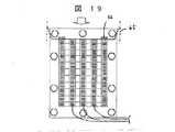
図示していないが、本実施例に用いたネストをケーシングに収容・装着すれば、空気圧縮機用の熱交換器が形成される。その際、ネストとケーシング間に生じる隙間をシール板46、47を用いてネスト入口側の周辺部でシールしている。この熱交換器を用いて、圧縮高温空気の冷却性能試験を行った。図18は、図16、17のA−A矢視断面図であり、ネスト長さの1/4の長さの位置における断面図である。この図11には、ガス温度の測定位置も併せ示している。上方から流入した高温空気は、ガス室51で冷却されながら下方へ流れる。ネストとケーシング゛壁65との間の隙間をシール板56でシールする。この隙間から、わずかな空気が漏れて、高温のままネスト出口側へ流れることが判明した。両端のガス室及び中間のガス室の出口に温度センサ61を設けガス温度を計測した。温度センサ60は入口温度を測定するために設けた。また、図19に、図16、17に示したネスト両端のガス室の入口を閉止板62で塞いだときの断面を示す。この図19は、図16、17のA−A矢視断面図である。中央寄り3列にガス室の出口温度を測定する温度センサを配置した。
【0015】
これら2つの場合の、温度測定結果を図20に示す。図20中の記号は、初めの数字が試験順番であり、次の数字が測定したガス室の位置を、最後の文字が断面位置をそれぞれ示している。例えば1−3Aの場合、最初の1はガス列5列で水室4列の試験Noであり、3はガス室の3列目を意味し、AはA−A断面位置を意味する。最初の数値が2の場合は、両端のガス室を封鎖した試験の結果である。この図から明らかなように、両端のガス室の出口温度は中央側のガス室出口温度に比較して大幅に高い。そして、両端のガス室を封鎖しても、中央よりのガス室の出口温度は殆ど変化がない。当然ながら、両方の試験では入口熱量を同じに合わせている。これより、伝熱面積が3/5になっても両端のガス室が無い場合の冷却性能が良いという結果が得られた。つまり、外側のガス室では、ケーシングとネスト間の隙間が大きくなったことに相当する。本実施例の熱交換器はネストをケーシングに収容する熱交換器であるので、ケーシングは高温流体によって暖められている。そして、高温流体の漏れが存在するので、ネスト両端のガス室流体に外側から熱が入力される結果、冷却性能が低下したものと推測される。
【0016】
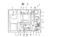
上記知見に基づく本発明のいくつかの実施例を、図1ないし図15を用いて説明する。図1〜図3は本発明に係る熱交換器を備えた2段スクリュー圧縮機の正面図、上面図及び側面図であり、パッケージを構成するカバーを取り除いて示した図である。図4及び図5は、熱交換器が収容されるケーシング部分の構造を示す断面図である。
【0017】
本実施例におけるスクリュー圧縮機は、低圧段(第1段)圧縮機と高圧段(2段)圧縮機を備える2段圧縮機である。取扱い流体は空気であり、吐出し圧力はゲージ圧で約0.7〜1.0MPa程度である。この圧縮機は、例えば一般産業用の工場空気源に用いられる。圧縮機の構成を以下に詳述する。低圧段圧縮機2及び高圧段圧縮機3は、増速機ケーシング5に取付けられ、各段の圧縮機が備えるロータは電動機4によって回転される。1段吸込み、1段吐出、2段吸込みおよび2段吐出の各空気通路は、増速機ケーシング5の内部を仕切壁で区切ることで形成される。各段の圧縮機で昇圧された高温空気は、それぞれの通路を通って、後述するインタークーラおよびアフタークーラで冷却される。これらのクーラには冷却水が冷却水配管21を経由して供給される。冷却水は、初めに水室カバー20に導かれ、ついでネストに導かれた後、出口配管22から排出される。スクリュー圧縮機は、オイルポンプ15、オイルクーラ16、吸込みフィルタ11、容量調節弁10、等の付属機器を有している。
【0018】
図4に、インタークーラの入口部とクーラの収容・装着状況を示す。この図4では圧縮段を省略している。1段圧縮機で昇圧された高温空気は、ケーシング内通路36を通ってインタークーラ室33に入る。図5に、インタークーラの出口部とアフタークーラの入口部を示す。この図5でも圧縮段を省略している。インタークーラで冷却された空気は、通路37を通って2段圧縮機に吸込まれる。2段圧縮機で昇圧された高温空気は、ケーシング内通路38を通ってアフタークーラ室34に流入する。本実施例では、ケーシングとクーラネストとに形成される隙間を、上部入口付近でシールしている。
【0019】
図6及び図7に、ネストの構造を示す。図6はネストの平面図であり、ガスの流入方向から見た図である。図7は、図6の側面図である。本実施例では、高温流体が上方から下方に向かって流れ、冷却水はその流れに直交するように下方から入り、上方から流れ出る。本実施例のネストはガス室41を4列、水室42を5列を有している。そして両端側に水室42が配置されている。一方、ガス室41は両側に水室を有している。図7において、ガス48は上方から下方へ流れ、冷却水49は前側管板43の下方から入り、後側水室ケース44で向きを変えた後、前側管板の上方から流れ出る。2種の作動流体が、仕切板45を隔てて直交して流れている。仕切板を通して高温室側から低温室側へ熱が伝熱される。ガス室にはコルゲート状のフィンが形成されている。ネストとケーシング間の隙間を、シール板46、47を用いてネスト入口側の周辺部でシールしている。なお、ネスト出口の周辺部もシールするようにしてもよい。
【0020】
図8に、図6および図7に示したクーラネストのB−B断面を示す。水室42を両端に配置し、ガス室41を全て水室で挟んでいる。本実施例のクーラネストを用いると、高温流体は水室に挟まれたガス室を通過するので、十分に冷却される。また、ケーシングとネストとの間をシール板46でシールしても完全なシールは困難であるが、僅かに漏れた高温流体が内部のガス室を流れる流体を加温することはなく、逆に漏れた高温流体が外側の冷却水によって冷却されるので、漏れたガスまで高効率に冷却できる。
【0021】
本発明の他の実施例を、図9から図15を用いて説明する。本実施例では、インタークーラやアフタークーラが単体で構成されている場合を取り上げているが、勿論複数の熱交換器が上記実施例のように一体化されていても良い。アフタークーラやインタークーラを構成する容器30の中に、コルゲートフィン型の熱交換器ネスト31が収容されている。熱交換器ネスト31の左右両側面の底部には、断面コの字状の固定部材88が設けられている。この固定部材88に対応する容器30の左右両内壁面に突起72が形成されている。
【0022】
突起72の上面にシール部材71を載せ、このシール部材71を固定部材88が形成する溝87に保持することにより、容器30内部の空間を高温空気48が流通する空間と、熱交換器ネスト31において熱交換して冷却された低温空気50が流通する空間に仕切る。その際、熱交換器ネスト31とシール部材71は、固定部材88の内壁面75とシール部材71の外表面74とを密着させることにより気密に保たれる。シール部材71は、ゴムなどの十分に弾性変形可能な材料である。なお、シール部材71の形状は、突起72との密着性及び固定部材88との密着性を考慮して、固定部材88側に切り欠き部を形成し、突起側72をテーパ状にしている。
【0023】
このように構成した本実施例では、シール部材71を低温空気50側に配置したので、ゴム等で作られたシール部材71の熱劣化を低減できる。シール部材71を熱交換器ネスト31の下側に配置したので、熱交換器ネスト31の重量によりシール部材71が圧縮変形し、シール面に確実に面圧を付与することができる。
【0024】
シール部材71をゴムなどの弾性変形可能な材料としたので、容器30の突起72が鋳肌面のように凹凸が大の面でも、すきまを生じることが無く、確実にシールできる。また、固定部材88の内壁面75とシール部材71の外表面26を密着させたので、熱交換器ネスト31を固定した際に生じる恐れのある隙間の発生を防止できる。
【0025】
ここで、シール部材71の厚さh(図9参照)は、熱交換器ネスト31の最下面となる固定部材88と管板89の底面8よりシール部材71が突起72に当接する面73が下方になるように設定する。これにより、熱交換器ネスト31を容器30内に取付ける際に、シール部材71を熱交換器ネスト31の自重で圧縮変形させることが可能になる。なお、シール部材71の突起72への当接面73と、固定部材88との当接面である外表面74とを、シール部材71の断面積よりも小面積としたので、シール部材71の接触面における剛性を小さくできる。これにより、シール部材71の外表面74を固定部材88の内壁面75に容易に接触させることができる。
【0026】
ところで、スクリュー圧縮機に用いられるインタークーラやアフタークーラ等の熱交換器の入口空気温度は、約200℃、圧力約0.1MPaにも達する。このような高温下で使用されるシール材料としては、耐熱性の高いエチレンプロピレンゴム、アクリルゴム、シリコーンゴムまたはフッ素ゴムなどを用いるのが望ましい。
【0027】
図9に示した実施例の変形例を、図11に示す。この図11は、正面図、上面図、及び側部断面図をあわせ示した3面図である。気体チューブシール76は、耐熱性と伸縮性に富む高分子材料をチューブ状に形成し、内部に空気などの気体を封止もしくは注入して形成される。チューブ型のシールを用いることにより、弾性変形量を増大させることができる。特に、気体封入口77と、容器30外部から気体封入口77に気体を封入する配管を設ければ、容器30に熱交換器ネスト31を固定したあとに、気体チューブシール76に気体を封入し加圧するだけで、信頼性の高いシールが得られる。また、熱交換器ネスト31を容器30から取り出すときは、チューブ76内の気体を抜くだけで、簡単に熱交換器ネスト31を容器30から取り出すことができる。チューブの材料としては、耐熱性・伸縮性の高いポリアセタールやフッ素樹脂などが好ましい。
【0028】
本発明のさらに他の変形例を、図12に示す。同図(イ)では、突起72の上に載置したシール部材71aに、熱交換器ネスト31の底部に設けた止め金78を介してシール部材の重量を負荷する。そして、止め金78と突起72とを外れ止め79を用いてクランプしている。他のクランプ方法としては、同図(ロ)に示すように、熱交換器ネスト31の側部最下方に設けた熱交換器固定板80と突起72間にシール部材71aを挟み、突起72及びシール部材71aを貫通するボルト33を熱交換器固定板80にネジ止めする方法がある。これらいずれの方法によっても、シール部材を弾性変形させて、確実にシールできる。なお、シール部材を熱交換器ネストに接着剤で固定すれば、熱交換器ネストとシール部材間の気体の漏れをより確実に防止できる。
【0029】
本発明のさらに他の変形例を、図13に示す。熱交換器ネスト31の底面に薄板92をこの熱交換器ネスト31の左右方向に延在して取り付け、この延在部に断面コの字状の溝板91をボルト90を用いて取付ける。そして、シール部材71を溝板91の溝87に保持している。本変形例によれば、熱交換器を作用させているうちに、固定ボルト90がたとえゆるんで落下しても、受け面93をシール部材71に形成したので、落下したボルト90の気体流路への流動を防止できる。
【0030】
図14及び図15に、上記各実施例及び変形例で示したシール部材71、71aを用いた熱交換器を部分断面斜視図で示す。なお、図15は表示の都合上、底面を左側に、右側面を下方に示している。圧縮機等から吐出された高温の空気48は、吸込み口28から吸込まれ、熱交換器ネスト31内で冷却水と熱交換して低温空気50となり、吐出口29から外部へ吐出される。冷却水の出入り口側には水室63が設けられている。熱交換器ネスト31は、上記実施例で詳述したように、水室(列)とガス室(列)を有し、それらはコルゲートフィン26、27を有している。図15において、各室間にはチューブプレート27があり、管板側にはアウターバー29が設けられている。
以上述べた各実施例及び変形例によれば、熱交換器の容器に熱交換器ネストを容易に着脱できるとともに、シールを確実に行えるので、信頼性及び効率の高い熱交換器が得られる。また、清掃点検時にはカバーを取り外すだけでよく、メンテナンス性が向上する。さらに、熱交換器出口の作動流体の温度を下げれば、圧縮機動力を低減でき省エネに貢献できる。
【0031】
【発明の効果】
以上詳述したように、本発明によればコンパクト形熱交換器において、低温室を高温室よりも1室(1列)多くして両端に低温室を配置したので、冷却性能の良いコンパクトな熱交換器を得ることができる。さらに、熱交換器内部のシール性能を向上できる。
【図面の簡単な説明】
【図1】本発明に係る熱交換器を有するスクリュー圧縮機の一実施例の正面図。
【図2】図1に示したスクリュー圧縮機の平面図。
【図3】図1に示したスクリュー圧縮機の側面図。
【図4】図1に示したスクリュー圧縮機のケーシングの断面図。
【図5】図4に示したケーシングの他の断面図。
【図6】本発明に係る熱交換器の一実施例の平面図。
【図7】図6に示した熱交換器の側面図。
【図8】本発明に係る熱交換器の他の実施例の断面図。
【図9】本発明に係る熱交換器のさらに他の実施例の部分断面側面図。
【図10】図9に示した熱交換器の正面図。
【図11】本発明に係るシール部材の他の実施例の3面図。
【図12】本発明に係るシール部材の変形例の断面図。
【図13】本発明に係るシール部材のさらに他の変形例の断面図。
【図14】本発明に係る熱交換器内を流れる空気の流れを説明する図。
【図15】本発明に係る水室及びガス室の詳細を説明する図。
【図16】予備試験に用いた熱交換器の平面図。
【図17】図16に示した熱交換器の側面図。
【図18】図16及び図17のA−A断面図。
【図19】図16及び図17のA−A断面で外側ガス室を封鎖した様子を説明する図。
【図20】予備試験における冷却性能を説明する図。
【符号の説明】
1・・・スクリュー圧縮機、2・・・1段圧縮機、3・・・2段圧縮機、4・・・電動機、5・・・増速機ケーシング、6・・・ベース、7・・・防音カバー、8・・・制御盤、9・・・起動盤、10・・・容量調節弁、11、11a・・・吸込みダクト、吸込みフィルタ、12、13・・・吐出配管、14・・・安全弁、15・・・オイルポンプ、16・・・オイルクーラ、17・・・オイルフィルタ、18・・・給油マニホールド、19・・・防振ゴム、20・・・クーラ水室ケース、21・・・給水配管、22・・・排水配管、23、24・・・冷却水母管、25・・・吐出サイレンサ、26・・・コルゲートフィン、27・・・コルゲートフィン、28・・・吸込み口、29・・・吐出口、30・・・容器、31・・・熱交換器ネスト、33・・・インタークーラ、34・・・アフタークーラ、35・・・1段吸込み通路、36・・・1段吐出通路、37・・・2段吸込み通路、38a、38b・・・2段吐出通路、39・・・チューブプレート、40・・・アウターバー、41、51・・・ガス室(列)、42、52・・・水室(列)、43、53・・・管板、44、54・・・後側冷却水室、45、55・・・ガス室と水室の仕切壁、46、46a、47、56、57・・・シール板、48、58・・・高温空気、49、59・・・冷却水、60、61・・・温度センサ、62・・・ガス室封鎖板、65・・・ケーシング壁面、71・・・シール部材、72・・・突起、73・・・当接面、74・・・外表面、75・・・内壁面、76・・・チューブ、77・・・気体封入口、78・・・止め金、79・・・外れ止め、80・・・固定板、81・・・ボルト、84・・・ボルト、87・・・溝、88・・・固定部材、89・・・管板、90・・・固定ボルト、91・・・溝板、92・・・薄板、93・・・受け面。[0001]
BACKGROUND OF THE INVENTION
The present invention relates to a small and medium capacity air compressor used for a power air source or the like in a factory, and more particularly to a heat exchanger provided in the compressor.
[0002]
[Prior art]
There are screw-type compressors and small turbo compressors as small and medium-capacity air compressors with discharge pressures of about 0.7 MPa in gauge pressure and outputs of less than 100 kW to several hundred kW, and they are used as power air sources in factories. . Examples of such an air compressor are described in JP-A-8-105386 and JP-A-2000-120585. In these publications, a laminated heat exchanger or a fin tube heat exchanger is used to cool the compressed air generated by a medium- and small-capacity turbo compressor.
[0003]
And in JP-A-8-105386, in order for the seal part of the gas cooler to have both rigidity and sealing properties, a gas cooler for cooling the compressed gas is inserted into the cooler shell through which the compressed gas is circulated with a predetermined gap, A seal portion that seals the gap and partitions the inside of the cooler shell into a high temperature side and a low temperature side is formed on the outer periphery of the gas cooler. The seal portion protrudes from the outer peripheral portion of the gas cooler and elastically contacts the inner wall of the cooler shell. Japanese Patent Application Laid-Open No. 2000-120585 discloses a pressure vessel having a pair of rails having a recess at one end in order to improve the seal reliability and maintainability, and then fits into the recess after running on the rail. It is described that the nest accommodated in the pressure vessel has a roller to be inserted.
[0004]
[Problems to be solved by the invention]
In each of the sealing methods described in the above prior art, the sealing performance is surely improved. However, since a complicated configuration is required, processing is complicated. In addition, when the nest is stored in the casing, the elastic seal becomes a resistance, and the assembling work is increased. Moreover, it was difficult to completely prevent leakage.
[0005]
The present invention has been made in view of the above-mentioned problems of the prior art, and an object thereof is to prevent a reduction in heat exchange efficiency due to leakage between the cooler nest and the casing with a simple structure. Another object of the present invention is to realize a high-performance heat exchanger capable of cooling a high-temperature fluid. The present invention aims to realize at least one of these objects.
[0006]
[Means for Solving the Problems]
In order to achieve the above object , the present invention has a heat exchanger nest in which a plurality of low temperature chambers through which a low temperature fluid flows and a plurality of high temperature chambers through which a high temperature fluid flows are alternately stacked via partition plates, A cross section provided at the bottom of the left and right side surfaces of the heat exchanger nest, wherein the flow direction of the low temperature fluid in the low greenhouse and the flow direction of the high temperature fluid in the high temperature chamber are substantially orthogonal, both ends in the stacking direction are low temperature chambers A U-shaped fixing member, a container that accommodates the heat exchanger nest and has protrusions formed on the left and right inner wall surfaces corresponding to the fixing member, and is placed on the upper surface of the protrusion and formed on the fixing member An elastically deformable seal member that is held in the U-shaped groove, and is cooled by exchanging heat in the space inside the container through which the high-temperature fluid flows and in the heat exchanger nest. The low-temperature fluid flows Partition the space, in which the sealing member is disposed in said cold fluid side.
[0007]
Furthermore, in the above, it is desirable that the low temperature fluid is cooling water and the high temperature fluid is compressed air.
[0008]
Furthermore, it is desirable that the screw compressor is provided with the heat exchanger for an air compressor described above.
[0009]
Further, in the above, it is preferable that a compressive load is applied to the seal member by the mass of the heat exchanger nest.
[0010]
Furthermore, in the above-described structure, it is preferable that the sealing member has a notch formed on the fixing member side and the protrusion side is tapered.
Moreover, it is desirable that at least one of ethylene propylene rubber, acrylic rubber, silicone rubber, and fluoro rubber is the main component of the sealing member.
Furthermore, the sealing member is preferably a gas tube seal in which a polymer material is formed in a tube shape and gas is sealed or injected therein.
[0011]
DETAILED DESCRIPTION OF THE INVENTION
Hereinafter, some embodiments of the present invention will be described with reference to the drawings. First, knowledge based on the preliminary test according to the present invention will be described. In the heat exchanger according to the present invention, two kinds of working fluids are formed with orthogonal flow paths across the partition plate, and two different kinds of working fluids circulate through the orthogonal flow paths. When the working fluid flows through the orthogonal flow paths, heat is transferred from the high temperature side high temperature chamber to the low temperature side low temperature chamber through the partition plate. Thereby, the fluid on the high temperature side is cooled. A high greenhouse and a low temperature room form a pair, and the pair is laminated in a plurality of layers to form a heat exchanger called a nest. An example of such a heat exchanger is described in page 261 of Heat Transfer Engineering Material (4th revised edition) published by the Japan Society of Mechanical Engineers. According to this publication, this type of heat exchanger is classified as a compact heat exchanger. In a compact heat exchanger, when cooling water is used for the low temperature chamber fluid and compressed air is used for the high temperature chamber fluid, the heat transfer coefficient on the high temperature chamber side is small, so corrugated fins are used, or slits called louvers are provided on the corrugated fins. It is intended to increase the heat transfer area and improve the heat transfer coefficient. It is easily considered to use a compact heat exchanger for the compressor by taking advantage of this small size and compactness. However, since the difference in heat transfer coefficient is large in the heat exchanger for an air compressor as described above, sufficient performance cannot be ensured by simply using a compact heat exchanger for the air compressor. Therefore, in consideration of the characteristics and economy of the compact heat exchanger, the present invention uses a nest in which the number of high-temperature chambers is larger than that of low-temperature chambers, as will be described in detail below.
[0012]
By the way, in order to increase the number of high temperature chambers in the nest to be larger than the number of low temperature chambers, a nest of four low temperature chambers is manufactured with five high temperature chambers, and the cooling performance is measured. There wasn't. Therefore, the temperature distribution of the fluid in the high-temperature chamber (hereinafter referred to as the gas chamber) at both ends, and the gas in the gas chamber sandwiched between the cold chambers (hereinafter referred to as the water chamber) on both sides in the middle The outlet temperature was measured. The result will be described with reference to FIGS. 16 and 17 are a plan view and a side view, respectively, of a corrugated fin heat exchanger nest designed as a cooler for an air compressor.
[0013]
The gas chambers 51 are arranged on both sides, and the total of the gas chambers 51 is five rows and the water chambers 52 are four rows. The heat transfer area on the air side, which has a lower thermal conductivity than water, is increased to balance the amount of heat passing between the water side and the air side. The gas flow direction 58 is from the upper side to the lower side in the figure, and the
[0014]
Although not shown, if the nest used in the present embodiment is accommodated and attached to the casing, a heat exchanger for the air compressor is formed. At this time, the gap generated between the nest and the casing is sealed at the periphery on the nest entrance side using the
[0015]
The temperature measurement results in these two cases are shown in FIG. In the symbols in FIG. 20, the first number indicates the test order, the next number indicates the measured gas chamber position, and the last character indicates the cross-sectional position. For example, in the case of 1-3A, the first 1 is the test number of 5 rows of gas rows and 4 rows of water chambers, 3 means the third row of gas chambers, and A means the AA cross-sectional position. When the first numerical value is 2, it is the result of the test which sealed the gas chamber of both ends. As is apparent from this figure, the outlet temperatures of the gas chambers at both ends are significantly higher than the outlet temperature of the central gas chamber. And even if the gas chambers at both ends are sealed, the outlet temperature of the gas chamber from the center hardly changes. Of course, in both tests, the amount of inlet heat is matched. As a result, even when the heat transfer area was 3/5, the cooling performance was good when there were no gas chambers at both ends. That is, in the outer gas chamber, this corresponds to an increase in the gap between the casing and the nest. Since the heat exchanger of the present embodiment is a heat exchanger in which the nest is accommodated in the casing, the casing is heated by the high-temperature fluid. Since there is a leakage of high-temperature fluid, it is estimated that the cooling performance is reduced as a result of heat input from the outside to the gas chamber fluid at both ends of the nest.
[0016]
Several embodiments of the present invention based on the above findings will be described with reference to FIGS. 1 to 3 are a front view, a top view, and a side view of a two-stage screw compressor provided with a heat exchanger according to the present invention, and is a view that shows a package that is removed. 4 and 5 are cross-sectional views showing the structure of the casing portion in which the heat exchanger is accommodated.
[0017]
The screw compressor in the present embodiment is a two-stage compressor including a low-pressure stage (first stage) compressor and a high-pressure stage (two-stage) compressor. The handling fluid is air, and the discharge pressure is about 0.7 to 1.0 MPa in terms of gauge pressure. This compressor is used, for example, as a factory air source for general industries. The configuration of the compressor will be described in detail below. The low-
[0018]
FIG. 4 shows the intercooler inlet and the state of accommodation and mounting of the cooler. In FIG. 4, the compression stage is omitted. The high-temperature air pressurized by the first-stage compressor enters the
[0019]
6 and 7 show the nest structure. FIG. 6 is a plan view of the nest as seen from the gas inflow direction. FIG. 7 is a side view of FIG. In this embodiment, the high-temperature fluid flows from the top to the bottom, and the cooling water enters from the bottom so as to be orthogonal to the flow, and flows out from the top. The nest of this embodiment has four rows of
[0020]
FIG. 8 shows a BB cross section of the cooler nest shown in FIGS. 6 and 7.
[0021]
Another embodiment of the present invention will be described with reference to FIGS. In the present embodiment, the case where the intercooler and the aftercooler are configured as a single unit is taken up, but of course, a plurality of heat exchangers may be integrated as in the above embodiment. A corrugated fin-type
[0022]
The
[0023]
In the present embodiment configured as described above, since the
[0024]
Since the
[0025]
Here, the thickness h (see FIG. 9) of the
[0026]
By the way, the inlet air temperature of a heat exchanger such as an intercooler or an aftercooler used in a screw compressor reaches about 200 ° C. and a pressure of about 0.1 MPa. As a sealing material used at such a high temperature, it is desirable to use ethylene-propylene rubber, acrylic rubber, silicone rubber, or fluorine rubber having high heat resistance.
[0027]
A modification of the embodiment shown in FIG. 9 is shown in FIG. FIG. 11 is a three-view diagram illustrating a front view, a top view, and a side sectional view. The gas tube seal 76 is formed by forming a polymer material rich in heat resistance and stretchability into a tube shape and sealing or injecting a gas such as air inside. By using a tube-type seal, the amount of elastic deformation can be increased. In particular, if a
[0028]
Another modification of the present invention is shown in FIG. In FIG. 6A, the weight of the seal member is loaded on the seal member 71 a placed on the
[0029]
Yet another modification of the present invention is shown in FIG. A
[0030]
14 and 15 are partial sectional perspective views of heat exchangers using the
According to each of the embodiments and modifications described above, the heat exchanger nest can be easily attached to and detached from the container of the heat exchanger, and since the sealing can be performed reliably, a highly reliable and efficient heat exchanger can be obtained. Further, it is only necessary to remove the cover at the time of cleaning inspection, and maintenance is improved. Furthermore, if the temperature of the working fluid at the outlet of the heat exchanger is lowered, the compressor power can be reduced, which can contribute to energy saving.
[0031]
【The invention's effect】
As described above in detail, according to the present invention, in the compact heat exchanger, the low temperature chamber is increased by one room (one row) than the high temperature chamber, and the low temperature chambers are arranged at both ends. A heat exchanger can be obtained. Furthermore, the sealing performance inside the heat exchanger can be improved.
[Brief description of the drawings]
FIG. 1 is a front view of an embodiment of a screw compressor having a heat exchanger according to the present invention.
FIG. 2 is a plan view of the screw compressor shown in FIG.
3 is a side view of the screw compressor shown in FIG. 1. FIG.
4 is a cross-sectional view of the casing of the screw compressor shown in FIG.
FIG. 5 is another cross-sectional view of the casing shown in FIG. 4;
FIG. 6 is a plan view of one embodiment of a heat exchanger according to the present invention.
7 is a side view of the heat exchanger shown in FIG. 6. FIG.
FIG. 8 is a cross-sectional view of another embodiment of the heat exchanger according to the present invention.
FIG. 9 is a partial cross-sectional side view of still another embodiment of the heat exchanger according to the present invention.
10 is a front view of the heat exchanger shown in FIG.
FIG. 11 is a three-side view of another embodiment of the sealing member according to the present invention.
FIG. 12 is a cross-sectional view of a modified example of the seal member according to the present invention.
FIG. 13 is a cross-sectional view of still another modification of the seal member according to the present invention.
FIG. 14 is a diagram for explaining the flow of air flowing in the heat exchanger according to the present invention.
FIG. 15 is a diagram illustrating details of a water chamber and a gas chamber according to the present invention.
FIG. 16 is a plan view of the heat exchanger used in the preliminary test.
17 is a side view of the heat exchanger shown in FIG.
18 is a cross-sectional view taken along line AA in FIGS. 16 and 17. FIG.
FIG. 19 is a view for explaining a state in which the outer gas chamber is sealed along the AA cross section of FIGS. 16 and 17;
FIG. 20 is a diagram for explaining cooling performance in a preliminary test.
[Explanation of symbols]
DESCRIPTION OF
Claims (7)
前記熱交換器ネストの左右両側面の底部に設けられた断面コの字状の固定部材と、
前記熱交換器ネストを収容し、前記固定部材に対応する左右両内壁面に突起が形成された容器と、
前記突起の上面に載せられ、前記固定部材に形成されたコの字状の溝に保持される弾性変形可能なシール部材と、
を備え、前記容器内部の空間を前記高温流体が流通する空間と、前記熱交換器ネストにおいて熱交換して冷却された前記低温流体が流通する空間に仕切り、前記シール部材を前記低温流体側に配置したことを特徴とする空気圧縮機用熱交換器。A heat exchanger nest in which a plurality of low temperature chambers through which a low temperature fluid flows and a plurality of high temperature chambers through which a high temperature fluid flows are alternately stacked via a partition plate, the flow direction of the low temperature fluid in the low temperature chamber and the high temperature The flow direction of the high-temperature fluid in the chamber is almost orthogonal, and both ends in the stacking direction are cold chambers ,
A fixing member having a U-shaped cross section provided at the bottom of the left and right side surfaces of the heat exchanger nest;
A container in which protrusions are formed on the left and right inner wall surfaces corresponding to the fixing member;
An elastically deformable seal member placed on the upper surface of the protrusion and held in a U-shaped groove formed in the fixing member;
Partitioning the space inside the container into a space in which the high-temperature fluid flows and a space in which the low-temperature fluid cooled by heat exchange in the heat exchanger nest flows, and the seal member on the low-temperature fluid side A heat exchanger for an air compressor characterized by being arranged .
Priority Applications (1)
| Application Number | Priority Date | Filing Date | Title |
|---|---|---|---|
| JP2001154768A JP3948221B2 (en) | 2000-10-31 | 2001-05-24 | Heat exchanger for air compressor |
Applications Claiming Priority (3)
| Application Number | Priority Date | Filing Date | Title |
|---|---|---|---|
| JP2000-337253 | 2000-10-31 | ||
| JP2000337253 | 2000-10-31 | ||
| JP2001154768A JP3948221B2 (en) | 2000-10-31 | 2001-05-24 | Heat exchanger for air compressor |
Publications (2)
| Publication Number | Publication Date |
|---|---|
| JP2002206876A JP2002206876A (en) | 2002-07-26 |
| JP3948221B2 true JP3948221B2 (en) | 2007-07-25 |
Family
ID=26603428
Family Applications (1)
| Application Number | Title | Priority Date | Filing Date |
|---|---|---|---|
| JP2001154768A Expired - Fee Related JP3948221B2 (en) | 2000-10-31 | 2001-05-24 | Heat exchanger for air compressor |
Country Status (1)
| Country | Link |
|---|---|
| JP (1) | JP3948221B2 (en) |
Families Citing this family (2)
| Publication number | Priority date | Publication date | Assignee | Title |
|---|---|---|---|---|
| JP6173820B2 (en) | 2013-08-01 | 2017-08-02 | 株式会社神戸製鋼所 | Heat exchanger for gas compressor |
| CN116498552B (en) * | 2023-06-21 | 2023-09-08 | 泉州市中力机电有限公司 | Screw air compressor and cooling structure thereof |
-
2001
- 2001-05-24 JP JP2001154768A patent/JP3948221B2/en not_active Expired - Fee Related
Also Published As
| Publication number | Publication date |
|---|---|
| JP2002206876A (en) | 2002-07-26 |
Similar Documents
| Publication | Publication Date | Title |
|---|---|---|
| US8695574B2 (en) | Intake manifold having an integrated charge air cooler | |
| US9373873B2 (en) | Cooling system for automotive battery | |
| KR100390298B1 (en) | Heat exchanger for air compressor | |
| JP4580366B2 (en) | Intercooler for internal combustion engine | |
| US20130047661A1 (en) | Device for compressing and drying gas | |
| JP2007506928A (en) | Multi-stage heat exchange device and method for manufacturing such a device | |
| JP6111083B2 (en) | Compression device | |
| JP2007303812A (en) | Multipath liquid-cooled supply air cooler having cooling liquid bypass port for improved flow distribution | |
| JP6383801B2 (en) | Heat exchanger for motor vehicles | |
| JP6540190B2 (en) | Cold storage heat exchanger | |
| US9016355B2 (en) | Compound type heat exchanger | |
| CN114502899A (en) | Solid Cooling Module | |
| JP3948221B2 (en) | Heat exchanger for air compressor | |
| JP6087713B2 (en) | Compression device | |
| JP6607960B2 (en) | Gas compressor | |
| JP7344230B2 (en) | Plate fin heat exchanger for pump assembly | |
| JP4685474B2 (en) | Oil-free screw air compressor | |
| JP3569977B2 (en) | Seal structure of compressor gas cooler | |
| US20100126704A1 (en) | Heat Exchanger with Direct Flow Path Modules | |
| KR20160111505A (en) | Engine | |
| US11761444B2 (en) | Vacuum pump cooler for cooling a pumped fluid in a multistage vacuum pump | |
| US20130058817A1 (en) | Surface heat exchanger for compressible fluid alternative volumetric machines | |
| CN112832988B (en) | Cooler of compressor | |
| EP3312530A1 (en) | Heat exchange device | |
| US20240244792A1 (en) | Systems and methods for two-phase cold plate cooling |
Legal Events
| Date | Code | Title | Description |
|---|---|---|---|
| A621 | Written request for application examination |
Free format text: JAPANESE INTERMEDIATE CODE: A621 Effective date: 20040311 |
|
| RD01 | Notification of change of attorney |
Free format text: JAPANESE INTERMEDIATE CODE: A7421 Effective date: 20060418 |
|
| A711 | Notification of change in applicant |
Free format text: JAPANESE INTERMEDIATE CODE: A712 Effective date: 20060823 |
|
| A977 | Report on retrieval |
Free format text: JAPANESE INTERMEDIATE CODE: A971007 Effective date: 20061207 |
|
| A131 | Notification of reasons for refusal |
Free format text: JAPANESE INTERMEDIATE CODE: A131 Effective date: 20061219 |
|
| A521 | Written amendment |
Free format text: JAPANESE INTERMEDIATE CODE: A523 Effective date: 20070209 |
|
| TRDD | Decision of grant or rejection written | ||
| A01 | Written decision to grant a patent or to grant a registration (utility model) |
Free format text: JAPANESE INTERMEDIATE CODE: A01 Effective date: 20070327 |
|
| A61 | First payment of annual fees (during grant procedure) |
Free format text: JAPANESE INTERMEDIATE CODE: A61 Effective date: 20070409 |
|
| R150 | Certificate of patent or registration of utility model |
Free format text: JAPANESE INTERMEDIATE CODE: R150 |
|
| FPAY | Renewal fee payment (event date is renewal date of database) |
Free format text: PAYMENT UNTIL: 20100427 Year of fee payment: 3 |
|
| FPAY | Renewal fee payment (event date is renewal date of database) |
Free format text: PAYMENT UNTIL: 20110427 Year of fee payment: 4 |
|
| FPAY | Renewal fee payment (event date is renewal date of database) |
Free format text: PAYMENT UNTIL: 20120427 Year of fee payment: 5 |
|
| FPAY | Renewal fee payment (event date is renewal date of database) |
Free format text: PAYMENT UNTIL: 20130427 Year of fee payment: 6 |
|
| LAPS | Cancellation because of no payment of annual fees |