JP3946721B2 - Video decoding device - Google Patents
Video decoding device Download PDFInfo
- Publication number
- JP3946721B2 JP3946721B2 JP2004282844A JP2004282844A JP3946721B2 JP 3946721 B2 JP3946721 B2 JP 3946721B2 JP 2004282844 A JP2004282844 A JP 2004282844A JP 2004282844 A JP2004282844 A JP 2004282844A JP 3946721 B2 JP3946721 B2 JP 3946721B2
- Authority
- JP
- Japan
- Prior art keywords
- motion vector
- component
- field
- color difference
- luminance
- Prior art date
- Legal status (The legal status is an assumption and is not a legal conclusion. Google has not performed a legal analysis and makes no representation as to the accuracy of the status listed.)
- Expired - Lifetime
Links
- 239000013598 vector Substances 0.000 claims description 495
- 230000033001 locomotion Effects 0.000 claims description 469
- 238000000034 method Methods 0.000 claims description 50
- 238000004364 calculation method Methods 0.000 claims description 16
- 238000010586 diagram Methods 0.000 description 20
- 238000007796 conventional method Methods 0.000 description 7
- 238000004519 manufacturing process Methods 0.000 description 6
- 238000013139 quantization Methods 0.000 description 5
- 230000000875 corresponding effect Effects 0.000 description 4
- 230000005540 biological transmission Effects 0.000 description 3
- 238000009795 derivation Methods 0.000 description 3
- 230000014509 gene expression Effects 0.000 description 3
- 238000006073 displacement reaction Methods 0.000 description 2
- 230000009466 transformation Effects 0.000 description 2
- 230000002596 correlated effect Effects 0.000 description 1
- 230000007274 generation of a signal involved in cell-cell signaling Effects 0.000 description 1
- 238000010187 selection method Methods 0.000 description 1
Images


Description
本発明は、フィールド間予測モードを有する動画像符号化装置及び動画像装復号化装置、特に動画像装復号化装置に係わる。 The present invention relates to a moving picture encoding apparatus and a moving picture decoding apparatus having an inter-field prediction mode, and more particularly to a moving picture decoding apparatus.
動画像データは、一般に、データ量が大きいので、送信装置から受信装置へ伝送される際、あるいは記憶装置に格納される際などには、高能率符号化が行われる。ここで、「高能率符号化」とは、あるデータ列を他のデータ列に変換する符号化処理であって、そのデータ量を圧縮する処理をいう。 Since moving image data generally has a large amount of data, high-efficiency encoding is performed when it is transmitted from a transmission device to a reception device or stored in a storage device. Here, “high-efficiency encoding” refers to an encoding process for converting a data string into another data string and compressing the data amount.
動画像データは、主にフレームのみから構成されるものと、フィールドから構成されるものがある。以下、主に、フィールド画像を圧縮する方式の従来技術について説明する。
動画像データの高能率符号化方法としては、フレーム/フィールド間予測符号化方法が知られている。
There are moving image data mainly composed of only frames and data composed of fields. Hereinafter, the prior art of a method for compressing a field image will be mainly described.
As a high-efficiency encoding method for moving image data, a frame / field predictive encoding method is known.
図1は、このフレーム/フィールド間予測符号化のブロック図を示す。
この符号化方法では、動画像データが時間方向に相関性が高いことを利用する。図1の動作を簡単に説明すると、入力された原画像と予測画像との差分画像を減算機39にて生成し、その差分画像を直交変換手段31,量子化手段32及び係数エントロピー符号化手段40にて符号化する。また、量子化手段32の出力を逆量子化手段33及び逆直交変換手段34により差分画像を復元し、復号画像生成手段35にて復元した差分画像と符号化時に用いた予測画像とから符号化画像を復元する。その復元された画像は、復号画像記憶手段36に記憶され、動きベクトル計算手段37にて、次の入力画像との間の動きベクトルを計算し、その動きベクトルにより予測画像生成手段38にて予測画像を生成する。生成された動きベクトルはベクトルエントロピー符号化手段41にて符号化され、係数エントロピー符号化手段40で符号化された係数符号化データとともにMUX42を介して出力される。すなわち、動画像データは、一般に、あるタイミングのフレーム/フィールドデータと次のタイミングのフレーム/フィールドデータとの類似度が高いことが多いので、フレーム/フィールド間予測符号化方法では、その性質を使用する。例えば、フレーム/フィールド間予測符号化方法を用いたデータ伝送システムでは、送信装置において、前フレーム/フィールドの画像から対象フレーム/フィールドの画像への「動き」を表す動きベクトルデータ、及びその前フレーム/フィールドの画像からその動きベクトルデータを用いて作成した対象フレーム/フィールドの予測画像と対象フレーム/フィールドの実際の画像との差分データを生成し、それら動きベクトルデータおよび差分データを受信装置に送出する。一方、受信装置は、受信した動きベクトルデータおよび差分データから対象フレーム/フィールドの画像を再生する。
FIG. 1 shows a block diagram of this interframe / field predictive coding.
This encoding method utilizes the fact that moving image data is highly correlated in the time direction. The operation of FIG. 1 will be briefly described. A difference image between an input original image and a predicted image is generated by a
図1のこのフレーム/フィールド間予測符号化は、フレーム/フィールド間予測符号化の概略を説明したが、以下に、更にフレーム予測符号化、及びフィールド予測符号化について説明する。 This frame / field predictive coding in FIG. 1 has outlined the frame / field predictive coding. In the following, frame predictive coding and field predictive coding will be further described.
図2、及び、図3は、前述のISO/IEC MPEG-2/MPEG-4(以下MPEG-2、MPEG-4)、及び2002年8月現在において、ITU-TとISO/IECで共同で標準化中のITU-T H.264/ISO/IEC MPEG-4 Part 10(Advanced Video Coding:AVC)のFinal Committee Draft("Joint Final Committee Draft (JFCD) of Joint Video Specification(ITU-T REC, H.264|ISO/IEC 14496-10 AVC)", JVT-D157,あるいは、ISO/IEC JTC1/SO29/WG11 MPEG02/N492, July 2002, Klagenfurt, AT)(以下AVC FCDと省略)共通に用いられている、フィールド画像を符号化する際のフォーマットの説明である。 2 and 3 are the above-mentioned ISO / IEC MPEG-2 / MPEG-4 (hereinafter referred to as MPEG-2, MPEG-4) and as of August 2002, jointly by ITU-T and ISO / IEC. ITU-T H.264 / ISO / IEC MPEG-4 Part 10 (Advanced Video Coding: AVC) Final Committee Draft ("Joint Final Committee Draft (JFCD) of Joint Video Specification (ITU-T REC, H. 264 | ISO / IEC 14496-10 AVC) ", JVT-D157, or ISO / IEC JTC1 / SO29 / WG11 MPEG02 / N492, July 2002, Klagenfurt, AT) (hereinafter abbreviated as AVC FCD) This is a description of a format for encoding a field image.
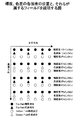
すなわち、各フレームは2枚のフィールド、すなわちTop フィールドとBottomフィールドから構成される。図2は、輝度、色差の各画素の位置と、それらが属するフィールドを説明する図である。この図2で示したとおり、輝度第1ライン(50a),輝度第3ライン(50b),輝度第5ライン(50c),輝度第7ライン(50d)・・・という、奇数番目のラインはTopフィールドに属し、輝度第2ライン(51a),輝度第4ライン(51b),輝度第6ライン(51c),輝度第8ライン(51d)・・・という偶数番目のラインはBottomフィールドに属する。色差成分も同様に、色差第1ライン(52a),色差第3ライン(52b)・・・といった奇数番目のラインはTopフィールドに属し、色差第2ライン(53a),色差第4ライン(53b)・・・といった偶数番目のラインはBottomフィールドに属する。 That is, each frame is composed of two fields, that is, a Top field and a Bottom field. FIG. 2 is a diagram for explaining the position of each pixel of luminance and color difference and the field to which they belong. As shown in FIG. 2, the odd-numbered lines such as the first luminance line (50a), the third luminance line (50b), the fifth luminance line (50c), the seventh luminance line (50d),. The even-numbered lines belonging to the field, the second luminance line (51a), the fourth luminance line (51b), the sixth luminance line (51c), the eighth luminance line (51d), etc. belong to the Bottom field. Similarly, the odd-numbered lines such as the first color difference line (52a), the third color difference line (52b),... Belong to the Top field, and the second color difference line (53a) and the fourth color difference line (53b). Even-numbered lines such as ... belong to the Bottom field.
このTopフィールドとBottomフィールドは、異なる時刻の画像をあらわす。次に、TopフィールドとBottomフィールドの時空間的な配置について、図3を用いて説明する。
なお、この図3以降、本発明に関わる技術は、動きベクトルの垂直成分に関わるものであるので、本明細書においては、水平成分の画素は図示せず、かつ、動きベクトルの水平成分は、全て、便宜上、0として説明する。また、各フィールドの輝度、色差の画素の位置関係は、正しく図示している。
The Top field and Bottom field represent images at different times. Next, the spatio-temporal arrangement of the Top field and the Bottom field will be described with reference to FIG.
3 and the subsequent drawings, since the technique related to the present invention relates to the vertical component of the motion vector, in this specification, the horizontal component pixel is not shown, and the horizontal component of the motion vector is All are described as 0 for convenience. Also, the positional relationship between the luminance and color difference pixels in each field is shown correctly.
この図3において縦軸は、各フィールドの垂直成分の画素位置を表し、横軸は時間の経過を表す。なお、各画像の画素の水平成分においては、フィールドによる位置の変位はないため、この図では水平方向の画素の図示及び説明は省略している。 In FIG. 3, the vertical axis represents the pixel position of the vertical component of each field, and the horizontal axis represents the passage of time. In the horizontal component of the pixel of each image, there is no displacement of the position due to the field, so the illustration and description of the pixel in the horizontal direction are omitted in this figure.
この図3で示したとおり、色差成分のピクセル位置は、輝度のフィールド内の画素位置に対して、垂直成分が1/4画素ずれている。なお、これは、Top及びBottomの両フィールドからフレームを構成した場合、図2のような画素位置の関係を満たすためである。各Top及びBottomの隣接する両フィールド間(64a:65a、65a:64b・・)については、NTSCフォーマットをベースにした場合では、約1/60秒である。そして、TopフィールドからTopフィールド(64a:64b・・)又はBottomフィールドからBottomフィールド(65a:65b・・)の時間は約1/30秒の間隔である。 As shown in FIG. 3, the pixel position of the color difference component is shifted by 1/4 pixel in the vertical component from the pixel position in the luminance field. This is because, when a frame is composed of both Top and Bottom fields, the pixel position relationship as shown in FIG. 2 is satisfied. The distance between adjacent fields of each Top and Bottom (64a: 65a, 65a: 64b,...) Is about 1/60 second when the NTSC format is used as a base. The time from the Top field to the Top field (64a: 64b...) Or from the Bottom field to the Bottom field (65a: 65b...) Is about 1/30 second.
以下、MPEG-2やAVC FCDで採用されている、フィールド画像のフレーム予測符号化モードとフィールド予測について、説明する。
図4は、フレーム予測モード時に、2枚の連続するフィールド(隣接するTop及びBottomのフィールド)からフレームを構成する方法を説明したものである。
Hereinafter, the frame predictive coding mode and field prediction of field images, which are employed in MPEG-2 and AVC FCD, will be described.
FIG. 4 illustrates a method of constructing a frame from two consecutive fields (adjacent Top and Bottom fields) in the frame prediction mode.
この図の様に、フレームは、時間的に連続する2枚のフィールド(Top及びBottomのフィールド)から再構成されたものである。
図5はフレーム予測モードを説明したものである。この図では、各フレーム84a、84b、84c・・は、図4で説明したとおり、2枚の連続するフィールド(Top及びBottomのフィールド)から、既に再構成されたものとする。このフレーム予測モードでは、Top及びBottomの両フィールドから構成された符号化対象フレームを対象に符号化が行なわれる。そして、参照画像としても、連続する参照用に蓄積された2枚のフィールド(Top及びBottomのフィールド)から一枚の参照フレームを構成し、前符号化対象フレームの予測に用いる。そして、この2枚のフレーム画像を、図1に図示したブロック図に従って符号化する。このフレーム予測符号化モードの場合、動きベクトルの表現方法については、ゼロベクトル、即ち (0,0)は、空間的に同位置の画素を指し示す。具体的にはFrame #2(84b)に属する輝度の画素82に対して、動きベクトル(0,0)を指し示す動きベクトルは、Frame#1(84a)の画素位置81を指し示すものである。
As shown in this figure, the frame is reconstructed from two temporally continuous fields (Top and Bottom fields).
FIG. 5 illustrates the frame prediction mode. In this figure, it is assumed that each
次にフィールド予測符号化モードについて説明する。
図6はフィールド間予測モード時の予測方法を説明する図である。フィールド予測モードでは、符号化対象は、原画として入力された一枚のTop フィールド(94a、94b・・)あるいはBottom フィールド(95a、95b・・)である。そして、参照画像としては、過去に蓄積されたTopフィールドあるいはBottomフィールドが使用可能である。ここで、原画フィールドと参照フィールドがパリティが同じ、とは、原画像のフィールドと参照フィールドが、両方ともTopフィールド、あるいは両方ともBottomフィールドであること、と一般に定義される。例えば、図中90の同パリティのフィールド予測は、原画(94b)、参照(94a)の両フィールドともTopフィールドである。同様に、原画フィールドと参照フィールドがパリティが異なる、とは、原画像のフィールドと参照フィールドの、一方がTopフィールド、もう片方がBottomフィールドであること、と一般に定義される。例えば、図中91に図示した異パリティのフィールド予測は、原画はBottom フィールド(95a)、参照はTopフィールド(94a)である。そして、この原画フィールド画像と参照フィールド画像を図1に図示したブロック図に従って符号化する。
Next, the field predictive coding mode will be described.
FIG. 6 is a diagram for explaining a prediction method in the inter-field prediction mode. In the field prediction mode, the encoding target is one Top field (94a, 94b...) Or Bottom field (95a, 95b...) Input as an original picture. As the reference image, the Top field or the Bottom field accumulated in the past can be used. Here, the parity of the original image field and the reference field is generally defined as both the field of the original image and the reference field being both the Top field or both being the Bottom field. For example, in the figure, the same-parity field prediction of 90 is the top field in both the original picture (94b) and the reference (94a) field. Similarly, the parity of the original picture field and the reference field is generally defined as one of the original picture field and the reference field, one being the Top field and the other being the Bottom field. For example, in the field prediction of different parity shown in FIG. 91, the original picture is the Bottom field (95a) and the reference is the Top field (94a). Then, the original picture field image and the reference field picture are encoded according to the block diagram shown in FIG.
なお、従来の技術では、フレームモード、及びフィールドモード、とも、各フレーム/フィールド内の画素の位置を元に、動きベクトルが求められている。従来方式における、動きベクトル算出方法、および、動きベクトルが与えられたときの、画素の対応付け方法について説明する。 In the conventional technique, a motion vector is obtained based on the position of a pixel in each frame / field in both the frame mode and the field mode. A motion vector calculation method and a pixel association method when a motion vector is given in the conventional method will be described.
図7は、MPEG-2, MPEG-1,AVC FCDなどの符号化で広く用いられている、フレーム/フィールド画像の座標を定義した図である。図中、白丸は、対象とするフレーム/フィールドで、画素の定義位置(181)である。ここで、このフレーム/フィールド画像内の座標については、画面内の左上を原点(0,0)とし、水平、垂直方向に、画素の定義位置が、順番に1,2,3・・・という値が割り振られる。すなわち、水平方向n番目、垂直方向m番目の画素の座標は(n,m)となる。これに準じて、画素と画素の間を補間した位置の座標も同様に定義される。すなわち、図中の黒丸の位置(180)に関しては、左上の画素から水平方向に1,5画素、垂直方向に2画素分のところにあるので、位置(180)の座標は(1.5, 2.0)と表される。なお、フィールド画像においては、垂直方向はフレーム画像の半分の画素しかないが、この場合でも、各フィールドに存在する画素の位置を基準に、図7と同様に取り扱う。 FIG. 7 is a diagram defining the coordinates of a frame / field image that is widely used in encoding such as MPEG-2, MPEG-1, and AVC FCD. In the figure, a white circle is a target frame / field and is a pixel definition position (181). Here, for the coordinates in this frame / field image, the upper left corner in the screen is the origin (0,0), and the pixel definition positions are 1, 2, 3,... In the horizontal and vertical directions. A value is allocated. That is, the coordinates of the nth pixel in the horizontal direction and the mth pixel in the vertical direction are (n, m). In accordance with this, the coordinates of the position interpolated between the pixels are similarly defined. That is, the position of the black circle in the figure (180) is 1,5 pixels in the horizontal direction and 2 pixels in the vertical direction from the upper left pixel, so the coordinates of the position (180) are (1.5, 2.0) It is expressed. In the field image, there are only half the pixels of the frame image in the vertical direction, but even in this case, it is handled in the same manner as in FIG. 7 with reference to the position of the pixel existing in each field.
この図7の座標系を用いて、フィールド間の動きベクトルの定義を説明する。
図8は、従来のフィールド間の対応する画素間の動きベクトルの算出方法を説明する図である。動きベクトルを定義するには、参照元の位置と参照先の位置が必要である。そして、この2点の間で動きベクトルが定義されることとなる。ここで、参照元のフィールド内の座標201が(Xs,Ys)の点 と参照先のフィールド内の座標202が(Xd,Yd)の点の間の動きベクトルを求める。従来のフィールド間に対応する画素間の動きベクトルの算出方法においては、参照元、および参照先が、Topフィールド、あるいはBottomフィールドに関わらず、以下に説明する、同一の方法で動きベクトルが求められていた。すなわち、参照元フィールド座標201(Xs,Ys)と、参照先フィールド座標202(Xd,Yd)が動きベクトル算出手段200に入力され、この二点間の動きベクトル203として、(Xd-Xs, Yd-Ys)が与えられるというものである。
The definition of motion vectors between fields will be described using the coordinate system of FIG.
FIG. 8 is a diagram for explaining a conventional method of calculating a motion vector between corresponding pixels between fields. To define a motion vector, a reference source position and a reference destination position are required. A motion vector is defined between these two points. Here, a motion vector between the point where the coordinate 201 in the reference source field is (Xs, Ys) and the coordinate 202 in the reference destination field is (Xd, Yd) is obtained. In the conventional method for calculating the motion vector between pixels corresponding to the fields, the motion vector is obtained by the same method described below regardless of whether the reference source and the reference destination are the Top field or the Bottom field. It was. That is, the reference source field coordinates 201 (Xs, Ys) and the reference destination field coordinates 202 (Xd, Yd) are input to the motion vector calculation means 200, and the
また、図9は、従来技術において、フィールド間で定義された動きベクトルが指し示す画素の算出方法を説明する図である。ここで、動きベクトルは、前述の図8の方法で導出したものとする。参照先の座標を求めるために、参照元の位置と動きベクトルが必要である。この図の場合には、参照元のフィールド内の座標212が(Xs,Ys)の点に対し、動きベクトル211の(X,Y)が与えられ、この両者を用いて求められる参照先フィールド内の座標を求めることを想定している。従来のフィールド間に対応する画素間の動きベクトルの算出方法においては、参照元、および参照先が、Topフィールド、あるいはBottomフィールドに関わらず、以下に説明する、同一の方法で参照先フィールドの位置が求められていた。すなわち、動きベクトル211(X、Y)と参照元フィールド座標212(Xs,Ys)が画素対応付け手段210に入力され、参照先フィールド座標213として、 座標(Xs+X, Ys+Y)が与えられるというものである。
FIG. 9 is a diagram for explaining a method of calculating pixels indicated by motion vectors defined between fields in the prior art. Here, it is assumed that the motion vector is derived by the method shown in FIG. In order to obtain the coordinates of the reference destination, the position of the reference source and the motion vector are required. In the case of this figure, the (X, Y) of the
上記の図9のベクトルと画素の位置との関係の定義は、輝度成分、及び色差成分で同一のものである。ここで、一般的な動画像符号化方式であるMPEG-1/MPEG-2/AVC FCDにおいては、ベクトルは輝度成分のみが符号化され、色差成分のベクトルは、輝度成分をスケーリングすることにより導出される。特にAVC FCDでは、色差成分は、縦の画素数、横の画素数とも輝度成分の画素数の半分のため、色差成分の予測画素を求めるための動きベクトルは、輝度成分の動きベクトルを正確に二分の一にスケーリングしたもの、と定められている。 The definition of the relationship between the vector and the pixel position in FIG. 9 is the same for the luminance component and the color difference component. Here, in MPEG-1 / MPEG-2 / AVC FCD, which is a general moving image encoding method, only a luminance component is encoded as a vector, and a color difference component vector is derived by scaling the luminance component. Is done. Especially in AVC FCD, since the color difference component is half the number of pixels of the luminance component for both the vertical and horizontal pixels, the motion vector for obtaining the predicted pixel of the color difference component is the exact motion vector of the luminance component. It is determined that it has been scaled by half.
図10は、このような従来の輝度成分動きベクトルから色差成分動きベクトルを求める方法を説明する図である。
すなわち、輝度の動きベクトル221を(MV_x,MV_y)、色差の動きベクトルを222を(MVC_x,MVC_y)とした場合、色差成分動きベクトル222は、色差成分動きベクトル生成手段220によって、
(MVC_x, MVC_y) = (MV_x/2, MV_y/2) ・・(式1)
という式に従って求められる。この導出方法は、従来方式では、動きベクトルが同一パリティのフィールド間、異なるパリティのフィールド間で予測を行なっているかどうかに関わらない。
FIG. 10 is a diagram for explaining a method for obtaining a color difference component motion vector from such a conventional luminance component motion vector.
That is, when the
(MVC_x, MVC_y) = (MV_x / 2, MV_y / 2) ・ ・ (Formula 1)
It is calculated according to the following formula. This derivation method does not depend on whether prediction is performed between fields with the same parity or between different parity fields in the conventional method.
なお、AVC FCDでは、輝度成分の動きベクトルの精度として、1/4画素精度を取ることが可能である。このことから、式1の結果として、色差成分の動きベクトルの精度として、1/8画素精度の小数点以下の精度を持つベクトルをとりうる。
In AVC FCD, it is possible to take 1/4 pixel accuracy as the accuracy of the motion vector of the luminance component. From this, as a result of
図11に基づいて、AVC FCDで定義された、色差成分の補間画素の算出方法を説明する。
図中、黒丸は整数画素を、点線白丸は補間画素を示している。ここで補間画素G(256)は、水平方向の座標は、点A(250)と点C(252)の各水平座標をα:1-αに内分したものであり、垂直方向の座標は、点A(250)と点B(251)の各垂直座標をβ:1-βに内分したものであるとする。ここでα及びβは0以上、1未満の値である。上記のような位置で定義される補間画素G(256)を算出する場合、その周囲の整数画素A(250)、B(251)、C(252)、D(253)とα、βを用いて、凡そ以下のように求められる。
Based on FIG. 11, a method of calculating interpolated pixels of color difference components defined by AVC FCD will be described.
In the figure, black circles indicate integer pixels, and dotted white circles indicate interpolation pixels. Here, the interpolation pixel G (256) is obtained by dividing the horizontal coordinates of the point A (250) and the point C (252) into α: 1-α, and the vertical coordinate is Suppose that the vertical coordinates of point A (250) and point B (251) are internally divided into β: 1-β. Here, α and β are values of 0 or more and less than 1. When calculating the interpolated pixel G (256) defined in the above position, the surrounding integer pixels A (250), B (251), C (252), D (253) and α, β are used. It is calculated as follows.
G=(1-α)・(1-β)・A+(1-α)・β・B+α・(1-β)・C+α・β・D (式2)
図11を用いた色差成分の画素の補間方法については、補間画素を求めるための一例であり、他の算出方法を用いても問題はない。
G = (1-α) ・ (1-β) ・ A + (1-α) ・ β ・ B + α ・ (1-β) ・ C + α ・ β ・ D (Formula 2)
The color difference component pixel interpolation method using FIG. 11 is an example for obtaining an interpolation pixel, and there is no problem even if other calculation methods are used.
このフィールド符号化モードの場合、原画フィールドと参照フィールドが異なる、すなわちパリティの異なるフィールド間の予測においては、AVC FCDの定義では、輝度成分と色差成分の両動きベクトルのゼロベクトルが平行ではない。即ち、従来の定義で、輝度成分の動きベクトルより求めた色差成分の動きベクトルを用いて予測をすると、輝度成分とは空間的にずれた位置の画素を用いることとなる。このことを図12を用いて説明する。図中、時間と共に、Topフィールド130、Bottomフィールド131、Top フィールド132が時間的に連続していると仮定する。ここで、Bottom フィールド131を、Top フィールド130を用いて符号化しようとしている。この際、フィールド間符号化では、各フィールドの同一ライン間の動きベクトルを垂直方向のゼロと定義している。このため、Bottomフィールド131に属する輝度の2ライン目画素133aに対して、ゼロベクトル(0,0)が割当てられた場合、この画素は、Topフィールド130の輝度の2ライン目の画素135aから予測される。同様に、Bottomフィールド131に属する1ライン目の色差の画素134aに対して、ゼロベクトル(0,0)が割当てられた場合、この画素は、Topフィールド130の色差の1ライン目の画素137aから予測される。また同様に、Topフィールド132に属する輝度の3ライン目の画素133b及び色差の2ライン目の画素134bはそれぞれ、Bottomフィールド131上の輝度の3ライン目の画素135b及び色差の2ライン目の画素137bから予測される。なお、本来、色差と輝度は、動きベクトルが平行であるほうが好ましいので、輝度の動きベクトルを、現在のままとすれば、本来の色差134a、134bの画素は、それぞれ136a、136bの位置から予測するべきものである。
In this field coding mode, in the prediction between fields with different original picture fields and reference fields, that is, with different parity, the zero vectors of both the luminance component and chrominance component motion vectors are not parallel in the definition of AVC FCD. That is, when prediction is performed using the motion vector of the chrominance component obtained from the motion vector of the luminance component according to the conventional definition, a pixel at a position spatially shifted from the luminance component is used. This will be described with reference to FIG. In the figure, it is assumed that the
前述のとおり、異なるパリティを持つフィールド間の予測では、
・輝度と色差のゼロベクトルが平行でない。
という点を説明した。この点が、異なるパリティを持つフィールド間の予測において、全てのベクトルに対しても、AVC FCDにおいて、以下のような問題を引き起こす。図13、及び、図14は、この問題を図示したものである。AVC FCDに従って、問題を示す。なお、本発明の課題は、動きベクトルの垂直成分のみに関わるものであるので、以降の説明では、動きベクトルの水平成分は、全て、便宜上、0とする。
As mentioned above, prediction between fields with different parity is
・ Zero vector of luminance and color difference is not parallel.
I explained that. This causes the following problem in AVC FCD for all vectors in prediction between fields having different parities. FIG. 13 and FIG. 14 illustrate this problem. Demonstrate the problem according to AVC FCD. Since the problem of the present invention relates only to the vertical component of the motion vector, in the following description, all the horizontal components of the motion vector are set to 0 for convenience.
図13は、参照先がBottomフィールドで、参照元がTopフィールドの場合の、従来技術における輝度成分動きベクトルから色差成分動きベクトルを求める際の問題点を説明する図である。 FIG. 13 is a diagram for explaining a problem in obtaining a color difference component motion vector from a luminance component motion vector in the prior art when the reference destination is the Bottom field and the reference source is the Top field.
AVC FCDでは、式1の通り、色差成分は、縦の画素数、横の画素数とも輝度成分の画素数の半分のため、色差成分の予測画素を求めるための動きベクトルは、輝度成分の動きベクトルを二分の一にスケーリングしたもの、と定められている。これは、動きベクトルがフレーム間、同一パリティのフィールド間、異なるパリティのフィールド間で予測を行なっているかどうかに関わらない。
In AVC FCD, as shown in
いま、この定義が、異なるパリティのフィールド間で定義された輝度の動きベクトルから、色差の動きベクトルを求める際に問題となることを示す。図13において、参照元Top フィールド輝度成分の1ライン目の画素140は、予測ベクトルとして(0,1)を有し、その結果、参照先Bottom フィールド輝度成分の2ライン目の画素位置141を予測値として指し示す。
Now, it is shown that this definition becomes a problem when a color difference motion vector is obtained from a luminance motion vector defined between different parity fields. In FIG. 13, the
この場合、同一ブロックに属する色差画素の動きベクトルは、式1に従って、動きベクトル(0,1/2)と求められる。そして、参照元Top フィールド色差成分の1ライン目の画素142の予測値として、動きベクトル(0,1/2)を用いて予測した場合、参照先Bottom フィールド色差成分の1ライン目の画素から1/2画素だけ下にずれた画素位置143を予測値として用いることとなる。
In this case, the motion vector of the color difference pixels belonging to the same block is obtained as a motion vector (0, 1/2) according to
この場合、輝度の動きベクトル(0,1)と色差の動きベクトル(0,1/2)は平行でない。好ましくは、輝度の動きベクトルと平行な色差の動きベクトルを適用した、参照先Bottomフィールドの色差成分の予測画素位置145を用いることが必要となる。 In this case, the luminance motion vector (0, 1) and the color difference motion vector (0, 1/2) are not parallel. Preferably, it is necessary to use the predicted pixel position 145 of the color difference component in the reference destination Bottom field to which a color difference motion vector parallel to the luminance motion vector is applied.
図14は、参照先がTopフィールドで、参照元がBottomフィールドの場合の、従来技術における輝度成分動きベクトルから色差成分動きベクトルを求める際の問題点を説明する図である。図13の説明と同様、図14において、参照元Bottomフィールド輝度成分の1ライン目の画素150は、予測ベクトルとして(0,1)を有し、その結果、参照先Topフィールド輝度成分の2ライン目の画素位置151を予測値として指し示す。
FIG. 14 is a diagram for explaining a problem in obtaining a color difference component motion vector from a luminance component motion vector in the prior art when the reference destination is the Top field and the reference source is the Bottom field. As in the description of FIG. 13, in FIG. 14, the
この場合、同一ブロックに属する色差画素の動きベクトルは、式1に従って、動きベクトル(0,1/2)と求められる。そして、参照元Bottomフィールド色差成分の1ライン目の画素152の予測値として、動きベクトル(0,1/2)を用いて予測した場合、参照先Topフィールド色差成分の1ライン目の画素から1/2画素だけ下にずれた画素位置153を予測値として用いることとなる。
In this case, the motion vector of the color difference pixels belonging to the same block is obtained as a motion vector (0, 1/2) according to
この場合、輝度の動きベクトル(0,1)と色差の動きベクトル(0,1/2)は平行でない。好ましくは、輝度の動きベクトルと平行な色差の動きベクトルを適用した、参照先Topフィールドの色差成分の予測画素位置155を用いることが必要となる。
In this case, the luminance motion vector (0, 1) and the color difference motion vector (0, 1/2) are not parallel. Preferably, it is necessary to use the predicted
以上のように、参照先と参照元のフィールドのパリティが異なる場合には、従来の予測方法では輝度と色差でずれた位置の画素を参照することとなり、ゼロベクトルばかりでなく、全てのベクトルで、予測画像で、輝度と色差でずれた予測画像となってしまう。 As described above, when the parity of the reference destination field differs from that of the reference source field, the conventional prediction method refers to the pixel at the position shifted by the luminance and the color difference, and not only the zero vector but all the vectors. The predicted image becomes a predicted image that is shifted due to the luminance and the color difference.
なお、上記説明では、輝度の動きベクトルと色差の動きベクトルについて時間方向の向き、すなわち、参照元フィールドから参照先フィールドへの時間軸方向も動きベクトルに含めた場合に、平行であるとか平行でないと言う意味に使っている。以下の説明においても同様である。 In the above description, the direction of the time direction of the luminance motion vector and the color difference motion vector, that is, the time axis direction from the reference source field to the reference destination field is included in the motion vector or is not parallel. It is used to mean. The same applies to the following description.
本発明の課題は、異なるフィールド画像間での符号化において、特に色差成分の予測効率を向上させ符号化効率を向上させることのできる動画像復号化方法、ないし動画像復号化装置を提供することである。 An object of the present invention is to provide a moving picture decoding method or a moving picture decoding apparatus capable of improving the prediction efficiency of color difference components and improving the encoding efficiency particularly in encoding between different field images. It is.
本発明は、上記の問題を解決するものである。
本発明の動画像復号化方法は、各フレームが2枚のフィールドで構成され、色差の垂直成分の画素数と輝度の垂直成分の画素数が異なる動画像信号に対し、フィールド間の動き補償予測を行い、復号化処理を行う動画像復号化方法において、
参照先フィールドがTopフィールドであり参照元フィールドがBottom フィールドのときには、ベクトル成分の値が4を単位としてフィールド画像の輝度成分の一画素分の垂直方向の動きを示す輝度成分の動きベクトルをMVy、ベクトル成分の値が8を単位としてフィールド画像の色差成分の一画素分の垂直方向の動きを示す色差成分の動きベクトルをMVCyとしたとき、
MVCy = MVy+ 2
で表される計算に基づいて、輝度成分の動きベクトルから色差成分の動きベクトルを生成することを特徴とする。
The present invention solves the above problems.
The moving picture decoding method according to the present invention provides motion compensation prediction between fields for a moving picture signal in which each frame is composed of two fields and the number of pixels of the vertical component of color difference and the number of pixels of the vertical component of luminance are different. In the moving picture decoding method for performing the decoding process,
When the reference field is the Top field and the reference field is the Bottom field, the motion vector of the luminance component indicating the vertical motion of one pixel of the luminance component of the field image in units of 4 as the vector component value is MVy, When the motion vector of the color difference component indicating the vertical motion of one pixel of the color difference component of the field image with the value of the vector component as a unit is MVCy,
MVCy =
The motion vector of the color difference component is generated from the motion vector of the luminance component based on the calculation expressed by
本発明の動画像復号化装置は、各フレームが2枚のフィールドで構成され、色差の垂直成分の画素数と輝度の垂直成分の画素数が異なる動画像信号に対し、フィールド間の動き補償予測を行い、復号化処理を行う動画像復号化装置において、
参照先フィールドがTopフィールドであり参照元フィールドがBottom フィールドのときには、ベクトル成分の値が4を単位としてフィールド画像の輝度成分の一画素分の垂直方向の動きを示す輝度成分の動きベクトルをMVy、ベクトル成分の値が8を単位としてフィールド画像の色差成分の一画素分の垂直方向の動きを示す色差成分の動きベクトルをMVCyとしたとき、
MVCy = MVy+ 2
で表される計算に基づいて、輝度成分の動きベクトルから色差成分の動きベクトルを
生成する手段を有することを特徴とする。
The moving picture decoding apparatus according to the present invention includes a motion compensation prediction between fields for a moving picture signal in which each frame is composed of two fields and the number of pixels of the vertical component of color difference and the number of pixels of the vertical component of luminance are different. In the video decoding device that performs the decoding process,
When the reference field is the Top field and the reference field is the Bottom field, the motion vector of the luminance component indicating the vertical motion of one pixel of the luminance component of the field image in units of 4 as the vector component value is MVy, When the motion vector of the color difference component indicating the vertical motion of one pixel of the color difference component of the field image with the value of the vector component as a unit is MVCy,
MVCy =
And a means for generating a color difference component motion vector from a luminance component motion vector.
本発明によれば、参照先フィールドと参照元フィールドのパリティに従って、それぞれに適した方法で生成された色差成分動きベクトルを使用するようにするので、輝度画素と色差画素の配置の違いやTop及びBottomフィールドへの割り当て方などにより生じる、色差成分動きベクトルの不具合を解消することが出来る。 According to the present invention, the chrominance component motion vector generated by a method suitable for each is used according to the parity of the reference destination field and the reference source field. The problem of the color difference component motion vector caused by the allocation to the Bottom field can be solved.
本発明によれば、パリティが異なるフィールド間においても、輝度成分の動きベクトルと平行な色差成分の動きベクトルを求めることが可能となり、従来方式で問題であった輝度成分と色成分の参照画素位置のずれといった課題を解決することができる。 According to the present invention, it is possible to obtain a motion vector of a color difference component parallel to a motion vector of a luminance component even between fields having different parities, and the reference pixel position of the luminance component and the color component, which has been a problem in the conventional method. It is possible to solve problems such as deviation.
まず、符号化における本発明の実施形態を説明する。
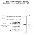
本発明の実施形態では、複数のフィールドで構成される動画像信号に対し、フィールド間の動き補償予測を行う動画像符号化方式において、輝度成分の動きベクトルから色差成分の動きベクトルを生成する複数の色差成分動きベクトル生成手段を備え、さらに、動きベクトルの参照先フィールドと参照元フィールドのパリティによって色差成分動きベクトルの生成に用いる色差成分動きベクトル生成手段を選択する選択手段をさらに備え、選択手段で選択された色差成分動きベクトル生成手段によって、輝度情報の動きベクトル情報から色差成分の予測ベクトルを生成することを特徴とする。ここで、選択手段では、輝度成分と平行な色差成分の動きベクトルを生成するものを選択する。
First, an embodiment of the present invention in encoding will be described.
In the embodiment of the present invention, in a moving image coding method for performing motion compensation prediction between fields for a moving image signal composed of a plurality of fields, a plurality of motion vectors of color difference components are generated from the motion vectors of luminance components. Color difference component motion vector generation means, and further comprises selection means for selecting color difference component motion vector generation means used for generation of the color difference component motion vector based on the parity of the reference destination field and the reference source field of the motion vector. The color difference component motion vector generation means selected in (1) generates a prediction vector of the color difference component from the motion vector information of the luminance information. Here, the selection means selects one that generates a motion vector of a color difference component parallel to the luminance component.
参照元フィールドから参照先フィールドの輝度成分動きベクトルに対して、参照元フィールドから参照先フィールドへの色差成分動きベクトルが平行であれば、参照元フィールドから参照先フィールドへの輝度成分動きベクトルと色差成分動きベクトルの空間的変位同じになるので、すなわち、輝度成分動きベクトルと色差成分動きベクトルの空間的位置関係が保たれるので、フィールド間における色ずれが無くなる。 If the color difference component motion vector from the reference source field to the reference destination field is parallel to the luminance component motion vector of the reference source field to the reference destination field, the luminance component motion vector and the color difference from the reference source field to the reference destination field Since the spatial displacements of the component motion vectors are the same, that is, the spatial positional relationship between the luminance component motion vector and the chrominance component motion vector is maintained, there is no color shift between fields.
ここで、重要なのは、従来技術において、数学的表現としての輝度成分動きベクトルと色差成分動きベクトルが平行であっても、各フィールドを構成する輝度ピクセル間の関係と色差ピクセル間の関係にマップしたとき、それぞれが平行にならないと言うことである。 Here, what is important is that, in the prior art, even if the luminance component motion vector and the color difference component motion vector as mathematical expressions are parallel, they are mapped to the relationship between the luminance pixels and the relationship between the color difference pixels constituting each field. Sometimes it is said that each does not become parallel.
ここで、前述の複数の色差成分動きベクトル生成手段としては、以下の3種類を備える。まず第一の色差成分動きベクトル生成手段は、参照先フィールドと参照元フィールドが同じパリティの際に、選択手段により選択されるものである。第二の色差成分動きベクトル生成手段は、参照先フィールドがTopフィールドであり参照元フィールドがBottom フィールドの際に、選択手段により選択されるものである。そして第三の色差成分動きベクトル生成手段は、参照先フィールドがBottomフィールドであり参照元フィールドがTop フィールドの際に、選択手段により選択されるものである。 Here, the plurality of color difference component motion vector generating means described above includes the following three types. First, the first chrominance component motion vector generation means is selected by the selection means when the reference destination field and the reference source field have the same parity. The second color difference component motion vector generation means is selected by the selection means when the reference destination field is the Top field and the reference source field is the Bottom field. The third color difference component motion vector generation means is selected by the selection means when the reference field is the Bottom field and the reference source field is the Top field.
輝度成分の動きベクトルと平行な色差成分の動きベクトルを求め方は、動きベクトルの参照元フィールドと参照先フィールドのパリティに依存し、それぞれ、両フィールドが同じパリティの場合、前者がTopフィールドで後者がBottomフィールドの場合、及び前者がBottomフィールドで後者がTopフィールドの場合、の3種類の場合で、計算方法が異なる。このことから、本発明の実施形態においては、参照元と参照先のフィールドによって、3種類の輝度成分の動きベクトルと平行な色差成分のベクトルを生成する手段の中から適当なものを選択して、色差成分の動きベクトルを生成する。 The method of obtaining the motion vector of the color difference component parallel to the motion vector of the luminance component depends on the parity of the reference field and the reference field of the motion vector. If both fields have the same parity, the former is the Top field and the latter The calculation method is different in the case where is the Bottom field, and the former is the Bottom field and the latter is the Top field. Therefore, in the embodiment of the present invention, an appropriate one is selected from the means for generating the vector of the color difference component parallel to the motion vector of the three luminance components according to the reference source and the reference destination fields. Then, a motion vector of the color difference component is generated.
具体的には、参照先フィールドと参照元フィールドが同じパリティの際に、第一の色差成分動きベクトル生成手段では、ベクトル成分の値が1を単位としてフィールド画像の輝度成分の一画素分の垂直方向の動きを示す輝度成分の動きベクトルをMVy、ベクトル成分の値が1を単位としてフィールド画像の色差成分の一画素分の垂直方向の動きを示す色差成分の動きベクトルをMVCyとしたとき
MVCy = MVy÷2
として求める。
Specifically, when the reference destination field and the reference source field have the same parity, the first chrominance component motion vector generation unit uses the unit of the vector component value of 1 as a unit for the vertical component of the luminance component of the field image. When the motion vector of the luminance component indicating the motion in the direction is MVy, and the motion vector of the color difference component indicating the vertical motion for one pixel of the color difference component of the field image in units of 1 as the vector component value is MVCy = MVCy = MVy ÷ 2
Asking.
そして、参照先フィールドがTopフィールドであり参照元フィールドがBottom フィールドの際に、第二の色差成分動きベクトル生成手段では、ベクトル成分の値が1を単位としてフィールド画像の輝度成分の一画素分の垂直方向の動きを示す輝度成分の動きベクトルをMVy、ベクトル成分の値が1を単位としてフィールド画像の色差成分の一画素分の垂直方向の動きを示す色差成分の動きベクトルをMVCyとしたとき
MVCy = MVy÷2 + 0.25
として求める。
When the reference destination field is the Top field and the reference source field is the Bottom field, the second chrominance component motion vector generation unit uses the unit of the vector component value of 1 as a unit of the luminance component of the field image. When the motion vector of the luminance component indicating the vertical motion is MVy, and the motion vector of the color difference component indicating the vertical motion of one pixel of the color difference component of the field image in units of 1 as the vector component value is MVCy. = MVy ÷ 2 + 0.25
Asking.
また、参照先フィールドがBottomフィールドであり参照元フィールドがTop フィールドの際に、第三の色差成分動きベクトル生成手段では、ベクトル成分の値が1を単位としてフィールド画像の輝度成分の一画素分の垂直方向の動きを示す輝度成分の動きベクトルをMVy、ベクトル成分の値が1を単位としてフィールド画像の色差成分の一画素分の垂直方向の動きを示す色差成分の動きベクトルをMVCyとしたとき
MVCy = MVy÷2 − 0.25
として求める。
When the reference field is the Bottom field and the reference source field is the Top field, the third chrominance component motion vector generation means uses the unit of the value of the vector component as one unit for the luminance component of the field image. When the motion vector of the luminance component indicating the vertical motion is MVy, and the motion vector of the color difference component indicating the vertical motion of one pixel of the color difference component of the field image in units of 1 as the vector component value is MVCy. = MVy ÷ 2 − 0.25
Asking.
また、定義によっては、輝度成分動きベクトルと色差成分動きベクトルの一画素分の動きを示す単位が異なる場合がある。ここで、輝度成分動きベクトルの定義が、4だけ変化したときに、1画素分の輝度画像内の動きを表すとし、色差成分動きベクトルの定義が、8だけ変化したときに、1画素分の色差画像内の動きを表すとした場合、参照先フィールドと参照元フィールドが同じパリティの際に、第一の色差成分動きベクトル生成手段では、輝度成分の動きベクトルをMVy、色差成分の動きベクトルをMVCyとしたとき
MVCy = MVy
として求める。
Depending on the definition, there may be a case in which the unit indicating the movement of one pixel of the luminance component motion vector and the color difference component motion vector is different. Here, when the definition of the luminance component motion vector changes by 4, it represents the motion in the luminance image for one pixel. When the definition of the color difference component motion vector changes by 8, the definition for one pixel When the motion in the color difference image is represented, when the reference field and the reference field have the same parity, the first color difference component motion vector generation means uses the motion vector of the luminance component as MVy and the motion vector of the color difference component as the motion vector. When MVCy, MVCy = MVy
Asking.
また、同様のベクトルの定義の場合、参照先フィールドがTopフィールドであり参照元フィールドがBottom フィールドの際に、第二の色差成分動きベクトル生成手段では、輝度成分の動きベクトルをMVy、色差成分の動きベクトルをMVCyとしたとき
MVCy = MVy + 2
として求める。
In the case of the same vector definition, when the reference field is the Top field and the reference source field is the Bottom field, the second chrominance component motion vector generation means sets the motion vector of the luminance component to MVy and the chrominance component of the chrominance component. When the motion vector is MVCy, MVCy =
Asking.
さらに、同様のベクトルの定義の場合、参照先フィールドがBottomフィールドであり参照元フィールドがTop フィールドの際に、第三の色差成分動きベクトル生成手段では、輝度成分の動きベクトルをMVy、色差成分の動きベクトルをMVCyとしたとき
MVCy = MVy − 2
として求める。
Further, in the case of the same vector definition, when the reference field is the Bottom field and the reference source field is the Top field, the third chrominance component motion vector generation means sets the luminance component motion vector to MVy and the chrominance component When the motion vector is MVCy, MVCy = MVy−2
Asking.
また、本発明の実施形態の符号化方法は、復号化方法としても使用できるので、基本的に復号装置においても、符号化装置と同様な機能を有し,同様に作用する。
以下の実施形態では、主に符号化装置について説明する。なお、本発明は、動きベクトルの垂直成分に関わるものであるので、動きベクトルの水平成分は、全て、便宜上、0とする。また、復号装置に関する実施形態も、符号化装置の実施形態と同様の構成をとる。
In addition, since the encoding method according to the embodiment of the present invention can be used as a decoding method, the decoding device basically has the same function as the encoding device and operates in the same manner.
In the following embodiments, an encoding device will be mainly described. Since the present invention relates to the vertical component of the motion vector, all the horizontal components of the motion vector are set to 0 for convenience. Also, the embodiment related to the decoding device has the same configuration as the embodiment of the encoding device.
以下、AVC FCDに本発明を適用した場合を想定して実施形態を説明する。
図15は、本発明の実施形態における、輝度成分動きベクトルから色差成分動きベクトルの算出方法を説明する図である。本実施形態における、フィールド予測における輝度成分の動きベクトルから色差成分の動きベクトルを生成する生成手段の実施形態においては、生成手段は、三種類の色差成分の動きベクトル生成手段と一つの選択手段から構成される。
Hereinafter, an embodiment will be described assuming that the present invention is applied to an AVC FCD.
FIG. 15 is a diagram illustrating a method for calculating a color difference component motion vector from a luminance component motion vector in the embodiment of the present invention. In the embodiment of the generating means for generating the color difference component motion vector from the luminance component motion vector in the field prediction in the present embodiment, the generating means includes three types of color difference component motion vector generating means and one selection means. Composed.
図15における本発明の実施形態の動作を以下に説明する。
まず、与えられた輝度成分の動きベクトル231を(MV_x,MV_y)とする。そして、この輝度成分のベクトルを、第一の色差成分動きベクトル生成手段233、第二の色差成分動きベクトル生成手段234、第三の色差成分動きベクトル生成手段235、の入力として与える。そして、それぞれの出力を選択手段230に入力する。そして、選択手段230では、入力された動きベクトルの参照元フィールドのパリティ237と動きベクトルの参照先のパリティ238の情報を元に、第一、第二、第三の色差成分動きベクトル生成手段の出力のうち一つを選択して、色差成分の動きベクトル232のベクトル成分(MVC_x, MVC_y)として出力する。
The operation of the embodiment of the present invention in FIG. 15 will be described below.
First, let the
図16は、第一の色差成分動きベクトル生成手段を説明する図である。
本実施形態においては、第一の色差成分動きベクトル生成手段260に対して、(MV_x, MV_y)のベクトル値をもつ輝度の動きベクトル261が入力され、(MVC1_x, MVC1_y)のベクトル値を持つ第一の色差の動きベクトル候補262を出力することを表している。そして、第一の色差の動きベクトル候補262は、色差成分動きベクトル生成手段260によって、輝度の動きベクトル261から、以下の式、
(MVC1_x, MVC1_y) = (MV_x/2, MV_y/2) ・・(式3)
に従って計算される。そして、求められた第一の色差の動きベクトル候補262は、選択手段へ出力される。
FIG. 16 is a diagram for explaining the first color difference component motion vector generation means.
In the present embodiment, a
(MVC1_x, MVC1_y) = (MV_x / 2, MV_y / 2) (Equation 3)
Calculated according to The obtained first color difference
図17は、第二の色差成分動きベクトル生成手段を説明する図である。
本実施形態においては、第二の色差成分動きベクトル生成手段270に対して、(MV_x, MV_y)のベクトル値をもつ輝度の動きベクトル271が入力され、(MVC2_x, MVC2_y)のベクトル値を持つ第二の色差の動きベクトル候補272を出力することを表している。そして、第二の色差の動きベクトル候補272は、色差成分動きベクトル生成手段270によって、輝度の動きベクトル271から、以下の式、
(MVC2_x, MVC2_y) = (MV_x/2, MV_y/2 + 1/4) ・・(式4)
に従って計算される。そして、求められた第二の色差の動きベクトル候補272は、選択手段へ出力される。
FIG. 17 is a diagram for explaining the second color difference component motion vector generation means.
In this embodiment, a
(MVC2_x, MVC2_y) = (MV_x / 2, MV_y / 2 + 1/4) ・ ・ (Formula 4)
Calculated according to Then, the obtained second color difference
図18は、第三の色差成分動きベクトル生成手段を説明する図である。
本実施形態においては、第三の色差成分動きベクトル生成手段280に対して、(MV_x, MV_y)のベクトル値をもつ輝度の動きベクトル281が入力され、(MVC3_x, MVC3_y)のベクトル値を持つ第三の色差の動きベクトル候補282を出力することを表している。そして、第三の色差の動きベクトル候補282は、色差成分動きベクトル生成手段280によって、輝度の動きベクトル281から、以下の式、
(MVC3_x, MVC3_y) = (MV_x/2, MV_y/2 − 1/4) ・・(式5)
に従って計算される。そして、求められた第三の色差の動きベクトル候補282は、選択手段へ出力される。
FIG. 18 is a diagram for explaining third color difference component motion vector generation means.
In the present embodiment, a
(MVC3_x, MVC3_y) = (MV_x / 2, MV_y / 2 − 1/4) ・ ・ (Formula 5)
Calculated according to Then, the obtained third color difference
図19は、本発明における選択手段240の実施形態を説明する図である。
まず、本実施形態では、動きベクトルの参照元フィールドのパリティ247と動きベクトルの参照先フィールドのパリティ248がそれぞれ、条件判断テーブル241によって判断され、選択すべき色差成分動きベクトル生成手段の選択情報249が出力される。本実施形態では、この条件判断テーブル241を用いると、参照先フィールド及び参照元フィールドの両方が等しい場合には、第一の色差成分動きベクトル候補244を選択すべき選択情報が出力される。また、参照先フィールドがTopフィールドで参照元フィールドがBottomフィールドの場合には第二の色差成分動きベクトル候補245を選択する選択情報が出力される。そして、参照先フィールドがBottomフィールドで参照元フィールドがTopフィールドの場合には第三の色差成分動きベクトル候補246を選択する選択情報が出力される。
FIG. 19 is a diagram for explaining an embodiment of the selection means 240 in the present invention.
First, in the present embodiment, the parity 247 of the motion vector reference source field and the parity 248 of the motion vector reference destination field are determined by the condition determination table 241, and
ここで、第一の色差成分動きベクトル候補244は図16の262に、第二の色差成分動きベクトル候補245は図17の272に、第三の色差成分動きベクトル候補246は図18の282に、それぞれ接続されている。そして、セレクタ243では、前述の選択情報249に従って、第一の色差成分動きベクトル候補244、第二の色差成分動きベクトル候補245、第三の色差成分動きベクトル候補246のうち一つを選択し、色差成分の動きベクトル242として(MVC_x,MVC_y)を出力する。
Here, the first chrominance component motion vector candidate 244 is at 262 in FIG. 16, the second chrominance component motion vector candidate 245 is at 272 in FIG. 17, and the third chrominance component
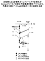
図20は、本発明の実施形態による、参照先がBottomフィールドで参照元がTopフィールドの場合の、輝度成分のベクトルから色差成分のベクトルを計算する例を示す図である。 FIG. 20 is a diagram illustrating an example of calculating a color difference component vector from a luminance component vector when the reference destination is the Bottom field and the reference source is the Top field according to the embodiment of the present invention.
この図の例では、参照元Top フィールド輝度成分の画素160を予測する輝度の動きベクトル(MV_x, MV_y)を(0, 1)とする。この場合、輝度の画素160の予測には参照先Bottom フィールド輝度成分の画素位置161が選択される。このようなベクトルに対して、本実施形態の図15の構成に従って、参照元Top フィールド色差成分の画素162の予測に用いるための、色差成分動きベクトルを求める過程を以下に説明する。
In the example of this figure, the luminance motion vector (MV_x, MV_y) for predicting the
まず、図20の場合には参照先フィールドがBottomフィールド、参照元フィールドがTopフィールドである。このことから、図19の条件判断テーブル241によって、選択情報249は第三の色差成分動きベクトル候補が選択される。ここで、式5に従えば、第三の色差成分動きベクトル候補は、
(MVC3_x, MVC3_y)=(MV_x/2, MV_y/2−1/4)=(0/2, 1/2 - 1/4)=(0, 1/4) (式6)
となる。そして、この値が図19の色差成分の動きベクトル242として出力される。このベクトル(0, 1/4)を参照元Top フィールド色差成分の画素162に適用すると、参照先Bottom フィールド色差成分の画素位置163が予測値として用いられることとなる。図20においては、各画素の縦方向の位置関係は実際の場合に即している。本図で分かるとおり、輝度成分動きベクトル(0,1)と色差成分動きベクトル(0,1/4)は平行であることが分かる。このことより、従来技術で問題となっていた、輝度成分と色差成分の色ずれが、本発明により解消されることとなる。
First, in the case of FIG. 20, the reference destination field is the Bottom field, and the reference source field is the Top field. Accordingly, the third color difference component motion vector candidate is selected as the
(MVC3_x, MVC3_y) = (MV_x / 2, MV_y / 2−1 / 4) = (0/2, 1/2-1/4) = (0, 1/4) (Formula 6)
It becomes. Then, this value is output as the motion vector 242 of the color difference component in FIG. When this vector (0, 1/4) is applied to the
同様に、図21は、本発明の実施形態による、参照先がTopフィールドで参照元がBottomフィールドの場合の、輝度成分のベクトルから色差成分のベクトルを計算する例を示す図である。 Similarly, FIG. 21 is a diagram showing an example of calculating a color difference component vector from a luminance component vector when the reference destination is the Top field and the reference source is the Bottom field according to the embodiment of the present invention.
この図の例では、参照元Bottomフィールド輝度成分の画素170を予測する輝度の動きベクトル(MV_x, MV_y)を(0, 1)とする。この場合、参照元Bottomフィールド輝度成分の画素170の予測には参照先Topフィールド輝度成分の画素位置171が選択される。このようなベクトルに対して、本実施形態の図14の構成に従って、参照元Bottomフィールド色差成分の画素172の予測に用いるための、色差成分動きベクトルを求める過程を以下に説明する。
In the example of this figure, the luminance motion vector (MV_x, MV_y) for predicting the
まず、図21の場合には参照先フィールドがTopフィールド、参照元フィールドがBottomフィールドである。このことから、図19の条件判断テーブル241によって、選択情報249は第二の色差成分動きベクトル候補が選択される。ここで、式4に従えば、第二の色差成分動きベクトル候補は、
(MVC2_x, MVC2_y)=(MV_x/2, MV_y/2+1/4)=(0/2, 1/2 + 1/4)=(0, 3/4) (式7)
となる。そして、この値が図19の色差成分の動きベクトル242として出力される。このベクトル(0, 3/4)を参照元Bottomフィールド色差成分の画素172に適用すると、予測に用いる位置として参照先Topフィールド色差成の画素位置173が予測値として用いられることとなる。図21においては、各画素の縦方向の位置関係は実際の場合に即している。本図で分かるとおり、輝度成分動きベクトル(0,1)と色差成分動きベクトル(0,3/4)は平行であることが分かる。このことより、従来技術で問題となっていた、輝度成分と色差成分の色ずれが、本発明により解消されることとなる。
First, in the case of FIG. 21, the reference field is the Top field, and the reference field is the Bottom field. From this, the second color difference component motion vector candidate is selected as the
(MVC2_x, MVC2_y) = (MV_x / 2, MV_y / 2 + 1/4) = (0/2, 1/2 + 1/4) = (0, 3/4) (Equation 7)
It becomes. Then, this value is output as the motion vector 242 of the color difference component in FIG. When this vector (0, 3/4) is applied to the
ここでは、図20、図21の例では、特定のベクトルの場合について説明したが、他の異パリティフィールド間の予測にも、本実施形態を適用することにより、輝度と色差のずれのない予測が可能となる。 Here, in the examples of FIGS. 20 and 21, the case of a specific vector has been described. However, by applying this embodiment to prediction between other different parity fields, prediction with no deviation between luminance and color difference is performed. Is possible.
なお、参照先及び参照元の両フィールドのパリティが等しい場合には、上記のような色ずれが発生しないため、図10の従来の輝度成分動きベクトルから色差成分動きベクトル生成手段220と同じ構成をもつ、本発明の第一の色差成分動きベクトル手段233の結果が選択されて色差成分動きベクトル232として用いられる。この場合は、本発明により得られる色差成分動きベクトルは従来技術の結果と同等なので、本実施形態における説明は割愛する。
In addition, when the parity of both the reference destination and the reference source is equal, the color shift as described above does not occur. Therefore, the same configuration as that of the chrominance component motion
また、別の本発明の実施形態では、輝度成分動きベクトル及び色差成分動きベクトルの単位の取り方によって、式(3)(4)(5)は異なる式となる。
図22〜図24は、本発明における第一の色差成分動きベクトル生成手段、第二の色差成分動きベクトル生成手段、第三の色差成分動きベクトル生成手段の別の実施形態を説明する図である。
In another embodiment of the present invention, the equations (3), (4), and (5) are different equations depending on how the units of the luminance component motion vector and the color difference component motion vector are determined.
22 to 24 are diagrams for explaining another embodiment of the first color difference component motion vector generation means, the second color difference component motion vector generation means, and the third color difference component motion vector generation means in the present invention. .
ここで、輝度成分動きベクトルの定義が、4だけ変化したときに、1画素分の輝度画像内の動きを表すとし、色差成分動きベクトルの定義が、8だけ変化したときに、1画素分の色差画像内の動きを表すとしたとき、第一の色差の動きベクトル候補262aは、色差成分動きベクトル生成手段260aによって、輝度の動きベクトル261aから、以下の式、
(MVC1_x, MVC1_y) = (MV_x, MV_y) ・・(式8)
に従って計算される。そして、求められた第一の色差の動きベクトル候補262aは、選択手段へ出力される。
Here, when the definition of the luminance component motion vector changes by 4, it represents the motion in the luminance image for one pixel. When the definition of the color difference component motion vector changes by 8, the definition for one pixel When representing the motion in the color difference image, the first color difference
(MVC1_x, MVC1_y) = (MV_x, MV_y) (Equation 8)
Calculated according to Then, the obtained first color difference
また第二の色差の動きベクトル候補272aは、色差成分動きベクトル生成手段270aによって、輝度の動きベクトル271aから、以下の式、
(MVC2_x, MVC2_y) = (MV_x, MV_y+2) ・・(式9)
に従って計算される。そして、求められた第二の色差の動きベクトル候補272aは、選択手段へ出力される。
Further, the second color difference
(MVC2_x, MVC2_y) = (MV_x, MV_y + 2) (Equation 9)
Calculated according to Then, the obtained second color difference
また第三の色差の動きベクトル候補282aは、色差成分動きベクトル生成手段280aによって、輝度の動きベクトル281aから、以下の式、
(MVC3_x, MVC3_y) = (MV_x, MV_y−2) ・・(式10)
に従って計算される。そして、求められた第二の色差の動きベクトル候補282aは、選択手段へ出力される。
なお、本実施形態は、AVC FCDを例として説明したが、ここでの説明は一実施形態であり、他の実施形態を制限するものではない。
Further, the third color difference
(MVC3_x, MVC3_y) = (MV_x, MV_y−2) (Equation 10)
Calculated according to Then, the obtained second color difference
Although the present embodiment has been described by taking AVC FCD as an example, the description here is one embodiment and does not limit other embodiments.
(付記1)
複数のフィールドで構成される動画像信号に対し、フィールド間の動き補償予測を行う動画像符号化方式において、
輝度成分の動きベクトルから色差成分の動きベクトルを生成する複数の色差成分動きベクトル生成手段と、
動きベクトルの参照先フィールドと参照元フィールドのパリティを入力として、色差成分動きベクトルの生成に用いる色差成分動きベクトル生成手段の一つを選択する選択手段を有し、
選択手段で選択された色差成分動きベクトル生成手段によって、輝度情報の動きベクトル情報から色差成分の予測ベクトルを生成することを特徴とする動画符号化装置。
(Appendix 1)
In a moving image coding method for performing motion compensation prediction between fields for a moving image signal composed of a plurality of fields,
A plurality of color difference component motion vector generation means for generating a color difference component motion vector from a luminance component motion vector;
Selection means for selecting one of the chrominance component motion vector generating means used for generating the chrominance component motion vector, using the parity of the motion vector reference destination field and the reference source field as inputs;
A moving picture encoding apparatus, wherein a color difference component motion vector generation unit selected by a selection unit generates a prediction vector of a color difference component from motion vector information of luminance information.
(付記2)
付記1において、輝度成分の動きベクトルから色差成分の動きベクトルを生成する色差成分動きベクトル生成手段として、
参照先フィールドと参照元フィールドが同じパリティの際に、選択手段により選択される第一の色差成分動きベクトル生成手段と、
参照先フィールドがTopフィールドであり参照元フィールドがBottom フィールドの際に、選択手段により選択される第二の色差成分動きベクトル生成手段と、
参照先フィールドがBottomフィールドであり参照元フィールドがTop フィールドの際に、選択手段により選択される第三の色差成分動きベクトル生成手段とを有することを特徴とする動画像符号化装置。
(Appendix 2)
In
A first color difference component motion vector generation unit selected by the selection unit when the reference destination field and the reference source field have the same parity;
When the reference field is the Top field and the reference field is the Bottom field, a second color difference component motion vector generation unit selected by the selection unit;
And a third color difference component motion vector generation unit selected by the selection unit when the reference destination field is the Bottom field and the reference source field is the Top field.
(付記3)
付記2において、第一の色差成分動きベクトル生成手段は、ベクトル成分の値が1を単位としてフィールド画像の輝度成分の一画素分の垂直方向の動きを示す輝度成分の動きベクトルをMVy、ベクトル成分の値が1を単位としてフィールド画像の色差成分の一画素分の垂直方向の動きを示す色差成分の動きベクトルをMVCyとしたとき
MVCy = MVy÷2
として求められることを特徴とする動画像符号化装置。
(Appendix 3)
In
A moving picture coding apparatus characterized by being obtained as follows.
(付記4)
付記2において、第二の色差成分動きベクトル生成手段は、ベクトル成分の値が1を単位としてフィールド画像の輝度成分の一画素分の垂直方向の動きを示す輝度成分の動きベクトルをMVy、ベクトル成分の値が1を単位としてフィールド画像の色差成分の一画素分の垂直方向の動きを示す色差成分の動きベクトルをMVCyとしたとき
MVCy = MVy÷2 + 0.25
として求められることを特徴とする動画像符号化装置。
(Appendix 4)
In
A moving picture coding apparatus characterized by being obtained as follows.
(付記5)
付記2において、第三の色差成分動きベクトル生成手段は、ベクトル成分の値が1を単位としてフィールド画像の輝度成分の一画素分の垂直方向の動きを示す輝度成分の動きベクトルをMVy、ベクトル成分の値が1を単位としてフィールド画像の色差成分の一画素分の垂直方向の動きを示す色差成分の動きベクトルをMVCyとしたとき
MVCy = MVy÷2 − 0.25
として求められることを特徴とする動画像符号化装置。
(Appendix 5)
In
A moving picture coding apparatus characterized by being obtained as follows.
(付記6)
付記2において、第一の色差成分動きベクトル生成手段は、ベクトル成分の値が4を単位としてフィールド画像の輝度成分の一画素分の垂直方向の動きを示す輝度成分の動きベクトルをMVy、ベクトル成分の値が8を単位としてフィールド画像の色差成分の一画素分の垂直方向の動きを示す色差成分の動きベクトルをMVCyとしたとき
MVCy = MVy
として求められることを特徴とする動画像符号化装置。
(Appendix 6)
In
A moving picture coding apparatus characterized by being obtained as follows.
(付記7)
付記2において、第二の色差成分動きベクトル生成手段は、ベクトル成分の値が4を単位としてフィールド画像の輝度成分の一画素分の垂直方向の動きを示す輝度成分の動きベクトルをMVy、ベクトル成分の値が8を単位としてフィールド画像の色差成分の一画素分の垂直方向の動きを示す色差成分の動きベクトルをMVCyとしたとき
MVCy = MVy + 2
として求められることを特徴とする動画像符号化装置。
(Appendix 7)
In
A moving picture coding apparatus characterized by being obtained as follows.
(付記8)
付記2において、第三の色差成分動きベクトル生成手段は、ベクトル成分の値が4を単位としてフィールド画像の輝度成分の一画素分の垂直方向の動きを示す輝度成分の動きベクトルをMVy、ベクトル成分の値が8を単位としてフィールド画像の色差成分の一画素分の垂直方向の動きを示す色差成分の動きベクトルをMVCyとしたとき
MVCy = MVy − 2
として求められることを特徴とする動画像符号化装置。
(Appendix 8)
In
A moving picture coding apparatus characterized by being obtained as follows.
(付記9)
複数のフィールドで構成される動画像信号に対しフィールド間の動き補償予測を行う動画像復号方式において、
輝度成分の動きベクトルから色差成分の動きベクトルを生成する複数の色差成分動きベクトル生成手段と、
動きベクトルの参照先フィールドと参照元フィールドのパリティを入力として、色差成分動きベクトルの生成に用いる色差成分動きベクトル生成手段の一つを選択する選択手段を有し、
選択手段で選択された色差成分動きベクトル生成手段によって、輝度情報の動きベクトル情報から色差成分の予測ベクトルを生成することを特徴とする動画像復号装置。
(Appendix 9)
In a video decoding system that performs motion compensation prediction between fields for a video signal composed of a plurality of fields,
A plurality of color difference component motion vector generation means for generating a color difference component motion vector from a luminance component motion vector;
Selection means for selecting one of the chrominance component motion vector generating means used for generating the chrominance component motion vector, using the parity of the motion vector reference destination field and the reference source field as inputs;
A moving picture decoding apparatus, characterized in that a color difference component prediction vector is generated from luminance vector motion vector information by a color difference component motion vector generation means selected by a selection means.
(付記10)
付記9において、輝度成分の動きベクトルから色差成分の動きベクトルを生成する色差成分動きベクトル生成手段として、
参照先フィールドと参照元フィールドが同じパリティの際に、選択手段により選択される第一の色差成分動きベクトル生成手段と、
参照先フィールドがTopフィールドであり参照元フィールドがBottom フィールドの際に、選択手段により選択される第ニの色差成分動きベクトル生成手段と、
参照先フィールドがBottomフィールドであり参照元フィールドがTop フィールドの際に、選択手段により選択される第三の色差成分動きベクトル生成手段とを有することを特徴とする動画像復号装置。
(Appendix 10)
In Supplementary Note 9, as chrominance component motion vector generation means for generating a chrominance component motion vector from a luminance component motion vector,
A first color difference component motion vector generation unit selected by the selection unit when the reference destination field and the reference source field have the same parity;
A second color difference component motion vector generation means selected by the selection means when the reference destination field is the Top field and the reference source field is the Bottom field;
A moving picture decoding apparatus comprising: third color difference component motion vector generation means selected by a selection means when the reference destination field is a Bottom field and the reference source field is a Top field.
(付記11)
付記10において、第一の色差成分動きベクトル生成手段は、ベクトル成分の値が1を単位としてフィールド画像の輝度成分の一画素分の垂直方向の動きを示す輝度成分の動きベクトルをMVy、ベクトル成分の値が1を単位としてフィールド画像の色差成分の一画素分の垂直方向の動きを示す色差成分の動きベクトルをMVCyとしたとき
MVCy = MVy÷2
として求められることを特徴とする動画像復号装置。
(Appendix 11)
In
A moving picture decoding apparatus characterized by being obtained as follows.
(付記12)
付記10において、第二の色差成分動きベクトル生成手段は、ベクトル成分の値が1を単位としてフィールド画像の輝度成分の一画素分の垂直方向の動きを示す輝度成分の動きベクトルをMVy、ベクトル成分の値が1を単位としてフィールド画像の色差成分の一画素分の垂直方向の動きを示す色差成分の動きベクトルをMVCyとしたとき
MVCy = MVy÷2 + 0.25
として求められることを特徴とする動画像復号装置。
(Appendix 12)
In
A moving picture decoding apparatus characterized by being obtained as follows.
(付記13)
付記10において、第三の色差成分動きベクトル生成手段は、ベクトル成分の値が1を単位としてフィールド画像の輝度成分の一画素分の垂直方向の動きを示す輝度成分の動きベクトルをMVy、ベクトル成分の値が1を単位としてフィールド画像の色差成分の一画素分の垂直方向の動きを示す色差成分の動きベクトルをMVCyとしたとき
MVCy = MVy÷2 − 0.25
として求められることを特徴とする動画像復号装置。
(Appendix 13)
In
A moving picture decoding apparatus characterized by being obtained as follows.
(付記14)
付記10において、第一の色差成分動きベクトル生成手段は、ベクトル成分の値が4を単位としてフィールド画像の輝度成分の一画素分の垂直方向の動きを示す輝度成分の動きベクトルをMVy、ベクトル成分の値が8を単位としてフィールド画像の色差成分の一画素分の垂直方向の動きを示す色差成分の動きベクトルをMVCyとしたとき
MVCy = MVy
として求められることを特徴とする動画像復号装置。
(Appendix 14)
In
A moving picture decoding apparatus characterized by being obtained as follows.
(付記15)
付記10において、第二の色差成分動きベクトル生成手段は、ベクトル成分の値が4を単位としてフィールド画像の輝度成分の一画素分の垂直方向の動きを示す輝度成分の動きベクトルをMVy、ベクトル成分の値が8を単位としてフィールド画像の色差成分の一画素分の垂直方向の動きを示す色差成分の動きベクトルをMVCyとしたとき
MVCy = MVy+ 2
として求められることを特徴とする動画像復号装置。
(Appendix 15)
In
A moving picture decoding apparatus characterized by being obtained as follows.
(付記16)
付記10において、第三の色差成分動きベクトル生成手段は、ベクトル成分の値が4を単位としてフィールド画像の輝度成分の一画素分の垂直方向の動きを示す輝度成分の動きベクトルをMVy、ベクトル成分の値が8を単位としてフィールド画像の色差成分の一画素分の垂直方向の動きを示す色差成分の動きベクトルをMVCyとしたとき
MVCy = MVy− 2
として求められることを特徴とする動画像復号装置。
(Appendix 16)
In
A moving picture decoding apparatus characterized by being obtained as follows.
(付記17)
複数のフィールドで構成される動画像信号に対し、フィールド間の動き補償予測を行う動画像符号化/復号方法において、
輝度成分の動きベクトルから色差成分の動きベクトルを生成する複数の色差成分動きベクトル生成手段を設けるステップと、
動きベクトルの参照先フィールドと参照元フィールドのパリティを入力として、色差成分動きベクトルの生成に用いる色差成分動きベクトル生成手段の一つを選択する選択ステップを有し、
選択ステップで選択された色差成分動きベクトル生成手段によって、輝度情報の動きベクトル情報から色差成分の予測ベクトルを生成することを特徴とする動画符号化/復号方法をコンピュータに実現させるプログラム。
(Appendix 17)
In a video encoding / decoding method for performing motion compensation prediction between fields for a video signal composed of a plurality of fields,
Providing a plurality of color difference component motion vector generating means for generating a color difference component motion vector from a luminance component motion vector;
A selection step of selecting one of the chrominance component motion vector generating means used for generating the chrominance component motion vector, using as input the parity of the motion vector reference destination field and the reference source field;
A program for causing a computer to realize a moving image encoding / decoding method, wherein a color difference component motion vector generation unit selected in the selection step generates a prediction vector of a color difference component from motion vector information of luminance information.
(付記18)
付記17において、輝度成分の動きベクトルから色差成分の動きベクトルを生成する色差成分動きベクトル生成手段として、
参照先フィールドと参照元フィールドが同じパリティの際に、選択ステップにより選択される第一の色差成分動きベクトル生成手段と、
参照先フィールドがTopフィールドであり参照元フィールドがBottom フィールドの際に、選択ステップにより選択される第二の色差成分動きベクトル生成手段と、
参照先フィールドがBottomフィールドであり参照元フィールドがTop フィールドの際に、選択ステップにより選択される第三の色差成分動きベクトル生成手段とを有することを特徴とするプログラム。
(Appendix 18)
In Supplementary Note 17, as chrominance component motion vector generation means for generating a chrominance component motion vector from a luminance component motion vector,
A first chrominance component motion vector generation unit selected by the selection step when the reference destination field and the reference source field have the same parity;
A second color difference component motion vector generation means selected by the selection step when the reference field is the Top field and the reference field is the Bottom field;
A program comprising: third color difference component motion vector generation means selected by a selection step when the reference destination field is a Bottom field and the reference source field is a Top field.
(付記19)
付記18において、第一の色差成分動きベクトル生成手段は、ベクトル成分の値が1を単位としてフィールド画像の輝度成分の一画素分の垂直方向の動きを示す輝度成分の動きベクトルをMVy、ベクトル成分の値が1を単位としてフィールド画像の色差成分の一画素分の垂直方向の動きを示す色差成分の動きベクトルをMVCyとしたとき
MVCy = MVy÷2
として求められることを特徴とするプログラム。
(Appendix 19)
In Supplementary Note 18, the first chrominance component motion vector generating means uses MVy as the motion vector of the luminance component indicating the vertical motion of one pixel of the luminance component of the field image with the value of the vector component as 1 unit, and the vector component MVCy = MVy ÷ 2 where MVCy is the motion vector of the color difference component indicating the vertical motion of one pixel of the color difference component of the field image with the value of 1 as the unit
A program characterized by being sought as
(付記20)
付記18において、第二の色差成分動きベクトル生成手段は、ベクトル成分の値が1を単位としてフィールド画像の輝度成分の一画素分の垂直方向の動きを示す輝度成分の動きベクトルをMVy、ベクトル成分の値が1を単位としてフィールド画像の色差成分の一画素分の垂直方向の動きを示す色差成分の動きベクトルをMVCyとしたとき
MVCy = MVy÷2 + 0.25
として求められることを特徴とするプログラム。
(Appendix 20)
In Supplementary Note 18, the second chrominance component motion vector generating means uses MVy as the motion vector of the luminance component indicating the vertical motion of one pixel of the luminance component of the field image with the value of the vector component as 1 unit, and the vector component MVCy = MVy ÷ 2 + 2 + 0.25, where MVCy is the motion vector of the color difference component indicating the vertical motion of one pixel of the color difference component of the field image with the value of 1 as the unit
A program characterized by being sought as
(付記21)
付記18において、第三の色差成分動きベクトル生成手段は、ベクトル成分の値が1を単位としてフィールド画像の輝度成分の一画素分の垂直方向の動きを示す輝度成分の動きベクトルをMVy、ベクトル成分の値が1を単位としてフィールド画像の色差成分の一画素分の垂直方向の動きを示す色差成分の動きベクトルをMVCyとしたとき
MVCy = MVy÷2 − 0.25
として求められることを特徴とするプログラム。
(Appendix 21)
In Supplementary Note 18, the third chrominance component motion vector generating means uses MVy as the motion vector of the luminance component indicating the vertical motion of one pixel of the luminance component of the field image with the value of the vector component as 1 unit, and the vector component MVCy = MVy ÷ 2−0.25, where MVCy is the motion vector of the color difference component indicating the vertical motion of one pixel of the color difference component of the field image with the value of 1 as the unit
A program characterized by being sought as
(付記22)
付記18において、第一の色差成分動きベクトル生成手段は、ベクトル成分の値が4を単位としてフィールド画像の輝度成分の一画素分の垂直方向の動きを示す輝度成分の動きベクトルをMVy、ベクトル成分の値が8を単位としてフィールド画像の色差成分の一画素分の垂直方向の動きを示す色差成分の動きベクトルをMVCyとしたとき
MVCy = MVy
として求められることを特徴とするプログラム。
(Appendix 22)
In Supplementary Note 18, the first chrominance component motion vector generation means uses MVy as the motion vector of the luminance component indicating the vertical motion of one pixel of the luminance component of the field image with the vector component value of 4 as a unit, and the vector component MVCy = MVy, where MVCy is the motion vector of the color difference component indicating the vertical motion of one pixel of the color difference component of the field image in units of 8
A program characterized by being sought as
(付記23)
付記18において、第二の色差成分動きベクトル生成手段は、ベクトル成分の値が4を単位としてフィールド画像の輝度成分の一画素分の垂直方向の動きを示す輝度成分の動きベクトルをMVy、ベクトル成分の値が8を単位としてフィールド画像の色差成分の一画素分の垂直方向の動きを示す色差成分の動きベクトルをMVCyとしたとき
MVCy = MVy + 2
として求められることを特徴とするプログラム。
(Appendix 23)
In Supplementary Note 18, the second chrominance component motion vector generating means uses MVy as the motion vector of the luminance component indicating the vertical motion of one pixel of the luminance component of the field image with the vector component value of 4 as a unit, and the vector component MVCy = MVy + 2 where MVCy is the motion vector of the color difference component indicating the vertical motion of one pixel of the color difference component of the field image in units of 8
A program characterized by being sought as
(付記24)
付記2において、第三の色差成分動きベクトル生成手段は、ベクトル成分の値が4を単位としてフィールド画像の輝度成分の一画素分の垂直方向の動きを示す輝度成分の動きベクトルをMVy、ベクトル成分の値が8を単位としてフィールド画像の色差成分の一画素分の垂直方向の動きを示す色差成分の動きベクトルをMVCyとしたとき
MVCy = MVy − 2
として求められることを特徴とするプログラム。
(Appendix 24)
In
A program characterized by being sought as
(付記25)
複数のフィールドで構成される動画像信号に対し、フィールド間の動き補償予測を行う動画像符号化/復号方法において、
輝度成分の動きベクトルから色差成分の動きベクトルを生成する複数の色差成分動きベクトル生成手段を設けるステップと、
動きベクトルの参照先フィールドと参照元フィールドのパリティを入力として、色差成分動きベクトルの生成に用いる色差成分動きベクトル生成手段の一つを選択する選択ステップを有し、
選択ステップで選択された色差成分動きベクトル生成手段によって、輝度情報の動きベクトル情報から色差成分の予測ベクトルを生成することを特徴とする動画符号化/復号方法。
(Appendix 25)
In a video encoding / decoding method for performing motion compensation prediction between fields for a video signal composed of a plurality of fields,
Providing a plurality of color difference component motion vector generating means for generating a color difference component motion vector from a luminance component motion vector;
A selection step of selecting one of the chrominance component motion vector generating means used for generating the chrominance component motion vector, using as input the parity of the motion vector reference destination field and the reference source field;
A moving picture encoding / decoding method, wherein a color difference component motion vector generation unit selected in the selection step generates a prediction vector of a color difference component from motion vector information of luminance information.
(付記26)
付記25において、輝度成分の動きベクトルから色差成分の動きベクトルを生成する色差成分動きベクトル生成手段として、
参照先フィールドと参照元フィールドが同じパリティの際に、選択ステップにより選択される第一の色差成分動きベクトル生成手段と、
参照先フィールドがTopフィールドであり参照元フィールドがBottom フィールドの際に、選択ステップにより選択される第二の色差成分動きベクトル生成手段と、
参照先フィールドがBottomフィールドであり参照元フィールドがTop フィールドの際に、選択ステップにより選択される第三の色差成分動きベクトル生成手段とを有することを特徴とする動画符号化/復号方法。
(Appendix 26)
In Supplementary Note 25, as chrominance component motion vector generation means for generating a chrominance component motion vector from a luminance component motion vector,
A first chrominance component motion vector generation unit selected by the selection step when the reference destination field and the reference source field have the same parity;
A second color difference component motion vector generation means selected by the selection step when the reference field is the Top field and the reference field is the Bottom field;
A moving image encoding / decoding method comprising: third color difference component motion vector generation means selected by a selection step when the reference destination field is a Bottom field and the reference source field is a Top field.
31 直交変換手段
32 量子化手段
33 逆量子化手段
34 逆直交変換手段
35 復号画像生成手段
36 復号画像記憶手段
37 動きベクトル計算手段
38 予測画像生成手段
39 予測誤差信号生成手段
40 係数エントロピー符号化手段
41 動きベクトルエントロピー符号化手段
42 多重化手段
50a-50d Top Field輝度第1,3,5,7ライン
51a-51d Bottom Field輝度第2,4,6,8ライン
52a-52b Top Field色差第1,3ライン
53a-53b Bottom Field色差第2,4ライン
64a-64c Top Field
65a-65c Bottom Field
81 Frame#1輝度成分
82 Frame#2輝度成分
84a-84c Frame#1〜#3
90 同パリティフィールド間予測
91 異パリティフィールド間予測
94a-94b Top Field
95a-95b Bottom Field
130 Top Field
131 Bottom Field
132 Top Field
133a-133b 符号化対象輝度成分
134a-134b 符号化対象色差成分
135a-135b 参照フィールドの輝度成分
136a-136b 予測として好ましい色差成分
137a-137b 参照フィールドの色差成分
140 参照元Top フィールド輝度成分の画素
141 予測値として用いられる参照先Bottom フィールド輝度成分の画素位置
142 参照元Top フィールド色差成分の画素
143 予測値として用いられる参照先Bottom フィールド色差成分の画素位置
145 好ましい色差成分の予測画素位置
150 参照元Bottomフィールド輝度成分の画素
151 予測値として用いられる参照先Topフィールド輝度成分の画素位置
152 参照元Bottomフィールド色差成分の画素
153 予測値として用いられる参照先Topフィールド色差成の画素位置
155 好ましい色差成分の予測画素位置
160 参照元Top フィールド輝度成分の画素
161 予測値として用いられる参照先Bottom フィールド輝度成分の画素位置
162 参照元Top フィールド色差成分の画素
163 予測値として用いられる参照先Bottom フィールド色差成分の画素位置
170 参照元Bottomフィールド輝度成分の画素
171 予測値として用いられる参照先Topフィールド輝度成分の画素位置
172 参照元Bottomフィールド色差成分の画素
・ 予測値として用いられる参照先Topフィールド色差成の画素位置
180 座標を求めたい位置
181 画素の定義位置
200 動きベクトル算出手段
201 参照元フィールド座標
202 参照先フィールド座標
203 動きベクトル
210 画素対応付け手段
211 動きベクトル
212 参照元フィールド座標
213 参照先フィールド座標
220 色差成分動きベクトル生成手段
221 輝度成分動きベクトル
222 色差成分動きベクトル
230 選択手段
231 輝度成分の動きベクトル
232 色差成分の動きベクトル
233 第一の色差成分動きベクトル生成手段
234 第二の色差成分動きベクトル生成手段
235 第三の色差成分動きベクトル生成手段
237 動きベクトルの参照元フィールドのパリティ
238 動きベクトルの参照先フィールドのパリティ
240 選択手段
241 条件判定テーブル
242 色差成分の動きベクトル
243 セレクタ
244 第一の色差成分動きベクトルの候補
245 第二の色差成分動きベクトルの候補
246 第三の色差成分動きベクトルの候補
247 動きベクトルの参照元フィールドのパリティ
248 動きベクトルの参照先フィールドのパリティ
249 選択情報
250〜255 整数画素
256 補間画素
260,260a 第一の色差成分動きベクトル生成手段
261,261a 輝度成分動きベクトル
262,262a 第一の色差成分動きベクトル候補
270,270a 第二の色差成分動きベクトル生成手段
271,271a 輝度成分動きベクトル
272,272a 第二の色差成分動きベクトル候補
280,280a 第三の色差成分動きベクトル生成手段
281,281a 輝度成分動きベクトル
282,282a 第三の色差成分動きベクトル候補
31 Orthogonal transformation means 32 Quantization means 33 Inverse quantization means 34 Inverse orthogonal transformation means 35 Decoded image generation means 36 Decoded image storage means 37 Motion vector calculation means 38 Predicted image generation means 39 Prediction error signal generation means 40 Coefficient entropy coding means 41 motion vector entropy encoding means 42 multiplexing means
50a-50d Top Field Luminance 1st, 3rd, 5th and 7th lines
51a-51d Bottom Field luminance 2nd, 4th, 6th, 8th lines
52a-52b Top Field color difference 1st and 3rd line
53a-53b Bottom Field 2nd and 4th color difference
64a-64c Top Field
65a-65c Bottom Field
81
82
84a-
90 Prediction between same parity fields
91 Prediction between different parity fields
94a-94b Top Field
95a-95b Bottom Field
130 Top Field
131 Bottom Field
132 Top Field
133a-133b Encoding target luminance component
134a-134b Color difference component to be encoded
135a-135b luminance component of reference field
136a-136b Preferred color difference component for prediction
137a-137b Color difference component of reference field
140 Reference source Top Field luminance component pixel
141 Pixel location of the referenced Bottom field luminance component used as the predicted value
142 Reference source Top Field color difference component pixels
143 Referenced Bottom field color difference component pixel position used as predicted value
145 Predicted pixel position of preferred color difference component
150 Reference bottom field luminance component pixels
151 Pixel location of reference top field luminance component used as prediction value
152 Referrer Bottom field pixel of color difference component
153 Referenced top field color difference pixel position used as prediction value
155 Predicted pixel position of preferred color difference component
160 Reference source Top Field luminance component pixel
161 Referenced Bottom Field luminance component pixel position used as prediction value
162 Reference source Top Field color difference component pixels
163 Referenced bottom field color difference component pixel position used as prediction value
170 Reference bottom field luminance component pixels
171 Pixel location of reference top field luminance component used as prediction value
172 Reference source bottom field color difference component pixels • Reference top field color difference pixel positions used as predicted values
180 Position to find coordinates
181 pixel definition position
200 Motion vector calculation means
201 Referrer field coordinates
202 Reference field coordinates
203 motion vector
210 Pixel matching means
211 motion vector
212 Reference field coordinates
213 Referenced field coordinates
220 Color difference component motion vector generation means
221 Luminance component motion vector
222 Color difference component motion vector
230 Selection method
231 Luminance component motion vector
232 Color difference component motion vector
233 First color difference component motion vector generation means
234 Second color difference component motion vector generation means
235 Third color difference component motion vector generation means
237 Parity of reference field of motion vector
238 Parity of reference field of motion vector
240 selection methods
241 Condition judgment table
242 Color difference component motion vector
243 selector
244 Candidate for first color difference component motion vector
245 Second color difference component motion vector candidate
246 Third Color Difference Component Motion Vector Candidate
247 Parity of motion vector reference field
248 Parity of reference field of motion vector
249 Selection information
250-255 integer pixels
256 interpolation pixels
260,260a First color difference component motion vector generation means
261,261a Luminance component motion vector
262,262a First color difference component motion vector candidate
270,270a Second color difference component motion vector generation means
271,271a Luminance component motion vector
272,272a Second color difference component motion vector candidate
280,280a Third color difference component motion vector generation means
281,281a Luminance component motion vector
282,282a Third color difference component motion vector candidate
Claims (5)
参照先フィールドがTopフィールドであり参照元フィールドがBottom フィールドのときには、ベクトル成分の値が4を単位としてフィールド画像の輝度成分の一画素分の垂直方向の動きを示す輝度成分の動きベクトルをMVy、ベクトル成分の値が8を単位としてフィールド画像の色差成分の一画素分の垂直方向の動きを示す色差成分の動きベクトルをMVCyとしたとき、
MVCy = MVy+ 2
で表される計算に基づいて、輝度成分の動きベクトルから色差成分の動きベクトルを生成することを特徴とする動画像復号化方法。 A moving image in which each frame is composed of two fields and motion compensation prediction between fields is performed on a moving image signal in which the number of pixels of the vertical component of color difference and the number of pixels of the vertical component of luminance are different , and decoding processing is performed. In the decryption method,
When the reference field is the Top field and the reference field is the Bottom field, the motion vector of the luminance component indicating the vertical motion of one pixel of the luminance component of the field image in units of 4 as the vector component value is MVy, When the motion vector of the color difference component indicating the vertical motion of one pixel of the color difference component of the field image with the value of the vector component as a unit is MVCy,
MVCy = MVy + 2
A moving picture decoding method, comprising: generating a motion vector of a color difference component from a motion vector of a luminance component based on a calculation represented by:
参照先フィールドと参照元フィールドがTopフィールドどうし又はBottomフィールドどうしのときには、
MVCy = MVy
で表される計算に基づいて、輝度成分の動きベクトルから色差成分の動きベクトルを生成することを特徴とする動画像復号化方法。 The moving picture decoding method according to claim 1,
When the reference field and the reference field are Top fields or Bottom fields,
MVCy = MVy
A moving picture decoding method, comprising: generating a motion vector of a color difference component from a motion vector of a luminance component based on a calculation represented by:
参照先フィールドがTopフィールドであり参照元フィールドがBottom フィールドのときには、ベクトル成分の値が4を単位としてフィールド画像の輝度成分の一画素分の垂直方向の動きを示す輝度成分の動きベクトルをMVy、ベクトル成分の値が8を単位としてフィールド画像の色差成分の一画素分の垂直方向の動きを示す色差成分の動きベクトルをMVCyとしたとき、
MVCy = MVy+ 2
で表される計算に基づいて、輝度成分の動きベクトルから色差成分の動きベクトルを
生成する手段を有することを特徴とする動画像復号化装置。 A moving image in which each frame is composed of two fields and motion compensation prediction between fields is performed on a moving image signal in which the number of pixels of the vertical component of color difference and the number of pixels of the vertical component of luminance are different , and decoding processing is performed. In the decryption device,
When the reference field is the Top field and the reference field is the Bottom field, the motion vector of the luminance component indicating the vertical motion of one pixel of the luminance component of the field image in units of 4 as the vector component value is MVy, When the motion vector of the color difference component indicating the vertical motion of one pixel of the color difference component of the field image with the value of the vector component as a unit is MVCy,
MVCy = MVy + 2
A moving picture decoding apparatus comprising means for generating a motion vector of a chrominance component from a motion vector of a luminance component based on a calculation represented by:
参照先フィールドと参照元フィールドがTopフィールドどうし又はBottomフィールドどうしのときには、
MVCy = MVy
で表される計算に基づいて、輝度成分の動きベクトルから色差成分の動きベクトルを生成する手段を有することを特徴とする動画像復号化装置。 The moving picture decoding apparatus according to claim 3,
When the reference field and the reference field are Top fields or Bottom fields,
MVCy = MVy
A moving picture decoding apparatus comprising means for generating a motion vector of a chrominance component from a motion vector of a luminance component based on a calculation represented by:
参照先フィールドと参照元フィールドのパリティに応じて、輝度成分の動きベクトルから色差成分の動きベクトルを生成するための前記計算方法を適応的に選択する手段を有することを特徴とする動画像復号化装置。 The moving picture decoding apparatus according to claim 4, wherein
Referring depending on the parity of the original field and the reference to field, video decoding, characterized in that it comprises means for adaptively selecting the computing method for generating a motion vector of the color difference component from the motion vector of the luminance component apparatus.
Priority Applications (1)
| Application Number | Priority Date | Filing Date | Title |
|---|---|---|---|
| JP2004282844A JP3946721B2 (en) | 2002-09-06 | 2004-09-28 | Video decoding device |
Applications Claiming Priority (2)
| Application Number | Priority Date | Filing Date | Title |
|---|---|---|---|
| JP2002261427 | 2002-09-06 | ||
| JP2004282844A JP3946721B2 (en) | 2002-09-06 | 2004-09-28 | Video decoding device |
Related Parent Applications (1)
| Application Number | Title | Priority Date | Filing Date |
|---|---|---|---|
| JP2003289350A Division JP3791922B2 (en) | 2002-09-06 | 2003-08-07 | Moving picture decoding apparatus and method |
Related Child Applications (2)
| Application Number | Title | Priority Date | Filing Date |
|---|---|---|---|
| JP2007054964A Division JP3946758B1 (en) | 2002-09-06 | 2007-03-06 | Moving picture decoding method and moving picture decoding apparatus |
| JP2007054965A Division JP3946759B1 (en) | 2002-09-06 | 2007-03-06 | Moving picture decoding method and moving picture decoding apparatus |
Publications (3)
| Publication Number | Publication Date |
|---|---|
| JP2005039857A JP2005039857A (en) | 2005-02-10 |
| JP2005039857A5 JP2005039857A5 (en) | 2007-04-19 |
| JP3946721B2 true JP3946721B2 (en) | 2007-07-18 |
Family
ID=34219803
Family Applications (1)
| Application Number | Title | Priority Date | Filing Date |
|---|---|---|---|
| JP2004282844A Expired - Lifetime JP3946721B2 (en) | 2002-09-06 | 2004-09-28 | Video decoding device |
Country Status (1)
| Country | Link |
|---|---|
| JP (1) | JP3946721B2 (en) |
-
2004
- 2004-09-28 JP JP2004282844A patent/JP3946721B2/en not_active Expired - Lifetime
Also Published As
| Publication number | Publication date |
|---|---|
| JP2005039857A (en) | 2005-02-10 |
Similar Documents
| Publication | Publication Date | Title |
|---|---|---|
| JP3791922B2 (en) | Moving picture decoding apparatus and method | |
| JP3946722B2 (en) | Video encoding device | |
| JP4158442B2 (en) | Video encoding method and video decoding method | |
| JP4144339B2 (en) | Video encoding method and video decoding method | |
| JP3946721B2 (en) | Video decoding device | |
| JP3946723B2 (en) | Video encoding device | |
| JP3946758B1 (en) | Moving picture decoding method and moving picture decoding apparatus | |
| JP3946759B1 (en) | Moving picture decoding method and moving picture decoding apparatus | |
| JP3946761B1 (en) | Moving picture coding method and moving picture coding apparatus | |
| JP3946760B1 (en) | Moving picture coding method and moving picture coding apparatus |
Legal Events
| Date | Code | Title | Description |
|---|---|---|---|
| A621 | Written request for application examination |
Free format text: JAPANESE INTERMEDIATE CODE: A621 Effective date: 20060222 |
|
| A621 | Written request for application examination |
Free format text: JAPANESE INTERMEDIATE CODE: A621 Effective date: 20060805 |
|
| A521 | Request for written amendment filed |
Free format text: JAPANESE INTERMEDIATE CODE: A523 Effective date: 20070306 |
|
| A871 | Explanation of circumstances concerning accelerated examination |
Free format text: JAPANESE INTERMEDIATE CODE: A871 Effective date: 20070306 |
|
| A975 | Report on accelerated examination |
Free format text: JAPANESE INTERMEDIATE CODE: A971005 Effective date: 20070328 |
|
| TRDD | Decision of grant or rejection written | ||
| A01 | Written decision to grant a patent or to grant a registration (utility model) |
Free format text: JAPANESE INTERMEDIATE CODE: A01 Effective date: 20070410 |
|
| A61 | First payment of annual fees (during grant procedure) |
Free format text: JAPANESE INTERMEDIATE CODE: A61 Effective date: 20070411 |
|
| R150 | Certificate of patent or registration of utility model |
Ref document number: 3946721 Country of ref document: JP Free format text: JAPANESE INTERMEDIATE CODE: R150 Free format text: JAPANESE INTERMEDIATE CODE: R150 |
|
| FPAY | Renewal fee payment (event date is renewal date of database) |
Free format text: PAYMENT UNTIL: 20110420 Year of fee payment: 4 |
|
| FPAY | Renewal fee payment (event date is renewal date of database) |
Free format text: PAYMENT UNTIL: 20110420 Year of fee payment: 4 |
|
| FPAY | Renewal fee payment (event date is renewal date of database) |
Free format text: PAYMENT UNTIL: 20120420 Year of fee payment: 5 |
|
| FPAY | Renewal fee payment (event date is renewal date of database) |
Free format text: PAYMENT UNTIL: 20130420 Year of fee payment: 6 |
|
| FPAY | Renewal fee payment (event date is renewal date of database) |
Free format text: PAYMENT UNTIL: 20140420 Year of fee payment: 7 |
|
| EXPY | Cancellation because of completion of term |