JP3945940B2 - Sample polishing method and sample polishing apparatus - Google Patents
Sample polishing method and sample polishing apparatus Download PDFInfo
- Publication number
- JP3945940B2 JP3945940B2 JP15573699A JP15573699A JP3945940B2 JP 3945940 B2 JP3945940 B2 JP 3945940B2 JP 15573699 A JP15573699 A JP 15573699A JP 15573699 A JP15573699 A JP 15573699A JP 3945940 B2 JP3945940 B2 JP 3945940B2
- Authority
- JP
- Japan
- Prior art keywords
- polishing
- dressing
- sample
- dress
- head
- Prior art date
- Legal status (The legal status is an assumption and is not a legal conclusion. Google has not performed a legal analysis and makes no representation as to the accuracy of the status listed.)
- Expired - Fee Related
Links
Images


Landscapes
- Finish Polishing, Edge Sharpening, And Grinding By Specific Grinding Devices (AREA)
- Mechanical Treatment Of Semiconductor (AREA)
- Grinding-Machine Dressing And Accessory Apparatuses (AREA)
Description
【0001】
【発明の属する技術分野】
本発明は、半導体基板等の試料の一面を研磨するための試料研磨方法、及びこの方法の実施に用いる装置に関する。
【0002】
【従来の技術】
シリコン基板等の半導体基板の表面に、導電体層、半導体層又は絶縁体層を積層形成する積層工程と、積層形成された各層の表面に回路パターンを形成するパターン形成工程とを繰り返して行われる半導体装置の製造においては、前記積層工程において得られた各層の表面への回路パターンの形成に支障を来すことのないよう、前記表面を研磨して平坦化するようにしている。
【0003】
このような半導体基板の表面研磨を良好に行わせるための研磨方法として、近年、化学機械研磨(Chemical Mechanical Polishing )が広く採用されている。図8は、以上の如き化学機械研磨に従来から用いられている試料研磨装置の要部の構成を模式的に示す側面図である。この試料研磨装置は、研磨対象となる半導体基板等の試料Wを、例えば真空吸着によってその下面に保持する保持台1と、該保持台1の下面にその上面を対向せしめた研磨定盤2とを備えて構成されている。
【0004】
前記保持台1及び研磨定盤2は、共に円板形をなし、夫々との対向面と直交する各別の支軸10,20により同軸的に支持され、これらの支軸10,20の軸回りに回転駆動されるようになしてある。保持台1との対向面となる研磨定盤2の上面には、ポリウレタン系樹脂、アクリル系樹脂等の樹脂製の研磨パッド3が、その全面に亘って張着されており、研磨定盤2の上部には、前記研磨パッド3上に研磨スラリを供給するノズル30が配してある。
【0005】
また研磨定盤2の上部には、前記保持台1と異なる位置に、前記研磨パッド3のドレッシング(目立て)を行うためのドレス用ヘッド4が、その下面を研磨パッド3の表面に臨ませて配してある。このドレス用ヘッド4は、研磨定盤2との対向面と直交する支軸40により同軸的に支持され、該支軸40の軸回りに回転駆動されると共に、研磨定盤2の半径方向に移動可能に構成してある。
【0006】
以上の如き試料研磨装置による化学機械研磨は、試料Wを保持する保持台1を研磨定盤2の上部の所定の円周上に位置決めし、該保持台1及び研磨定盤2を回転させつつ相互に接近させて、図中に2点鎖線により示す如く、前記試料Wの研磨面(下面)を前記研磨パッド3の表面に押し当て、これら両面を、前記ノズル30から供給される研磨スラリを介して摺接せしめて行われる。ノズル30から供給される研磨スラリは、研磨対象となる試料Wに応じて選定された研磨粒子と反応剤とを含んでおり、研磨パッド3に摺接せしめられた試料Wの研磨面は、研磨粒子の作用による機械的な研磨と、反応剤の作用による化学的な研磨とにより平坦化される。
【0007】
このように行われる化学機械研磨において、研磨定盤2に張着された研磨パッド3の表面性状は、試料Wとの摺接の繰り返しにより変化し、また研磨スラリに含まれる研磨粒子及び反応剤、並びに、研磨により発生する研磨屑による目詰まり(グレージング)によって変化して、所望の研磨レートが得られなくなる虞れがある。
【0008】
前記ドレス用ヘッド4によるドレッシングは、以上の如き研磨パッド3の表面性状の変化を修復し、研磨レートを回復させるために、例えば、所定回数の研磨が終了する都度行われるものであり、ドレス用ヘッド4と研磨定盤2とを回転させつつ相互に接近させて、性状が変化した研磨パッド3の表面にドレス用ヘッド4の下面(ドレス面)を押し当てて行われる。
【0009】
ドレス用ヘッド4のドレス面は、樹脂又は金属製の基材に、ダイヤモンド粒等の硬質粒を、夫々の一部を表面に露出させた状態で埋設して、該表面を粗面化して構成されており、研磨パッド3の表面は、粗面化されたドレス面の押し付けにより良好な表面性状に回復せしめられる。ドレス用ヘッド4は、前述の如く、研磨定盤2の半径方向に移動可能としてあり、研磨パッド3のドレッシングは、ドレス用ヘッド4の前記移動により、研磨パッド3の全面に亘って行わせることができる。なおこのとき、研磨パッド3の表面に水等の洗浄剤を供給し、目詰まりを生じさせている研磨粒子、反応剤、及び研磨屑を洗い流しつつドレッシングを行わせる場合もある。
【0010】
【発明が解決しようとする課題】
さて、以上の如き試料研磨装置において、研磨定盤2の上面に張着された研磨パッド3は、研磨の繰り返しに伴って徐々に劣化し、この劣化が過度に進行した場合、前記ドレッシングによる研磨レートの回復が期待し得なくなることから、所定回数の研磨がなされる都度、劣化した研磨パッド3を研磨定盤2から取り外し、新たな研磨パッド3に交換する必要がある。
【0011】
ところが、前記交換直後の新しい研磨パッド3は、安定した表面性状を有しているとは言えず、該研磨パッド3をそのまま用いて研磨を行わせた場合、所望の研磨レートが得られないという問題があることから、新しい研磨パッド3に対しても前述したドレッシングを実施し、表面性状を安定化させた後に研磨を開始させるようにしている。
【0012】
ところが、新規の研磨パッド3に対するドレッシングは、研磨レートの回復のために使用中の研磨パッド3に対してなされる通常のドレッシングよりも念入りに行う必要があり、このドレッシングに長い時間を要し、研磨パッド3を交換した後、この研磨パッド3を用いて研磨を開始するまでの間の立ち上げ時間が長くなり、研磨作業の能率低下を招くという問題があった。
【0013】
ドレッシング時間を短縮するためには、粗いドレス面を有するドレス用ヘッドを用い、単位時間当たりのドレッシング量を高めることが有効である。しかしながら、粗いドレス面を有するドレス用ヘッドを用いた場合、前述した通常のドレッシングに際しての時間管理が難しく、ドレッシング量の過不足が生じ易く、ドレッシングの不足により所望のドレッシング効果が得られなくなる虞れがあり、また逆に、過剰なドレッシングがなされ、各ドレッシング時における研磨パッド3の損耗量が大きくなって、該研磨パッド3の寿命の低下を引き起こすという問題がある。
【0014】
本発明は斯かる事情に鑑みてなされたものであり、研磨パッドの交換時におけるドレッシングの時間短縮を図ると共に、研磨レートの回復のために使用中の研磨パッドに対してなされる通常のドレッシングを安定して行わせることができる試料研磨方法及び試料研磨装置を提供することを目的とする。
【0015】
【課題を解決するための手段】
本発明に係る試料研磨方法は、試料台に保持された試料の一面を研磨定盤に張着された研磨パッドの表面に押し当て、両者間に研磨スラリを供給しつつ摺接させて前記試料の一面を研磨する一方、前記研磨パッドの表面にドレス用ヘッドのドレス面を押し当て、前記表面をドレッシングする試料研磨方法において、粗さの異なるドレス面を有する第1,第2のドレス用ヘッドを用い、研磨により均された研磨パッドの表面のドレッシングを、相対的に細かいドレス面を有する第1のドレス用ヘッドにより実施し、研磨定盤に新たに張着された研磨パッドの表面のドレッシングを、相対的に粗いドレス面を有する第2のドレス用ヘッドにより実施することを特徴とする。
【0016】
本発明においては、相対的に細かいドレス面を有し、ドレッシング量を抑えた第1のドレス用ヘッドと、相対的に粗いドレス面を有し、ドレッシング量を高めた第2のドレス用ヘッドとを用い、研磨により均された研磨パッドの表面のドレッシングに際しては第1のドレス用ヘッドを用い、このドレッシングを安定して行わせて、研磨パッドの損耗を抑えつつ、目的となる研磨レートの回復を実現する一方、研磨定盤に新たに張着した研磨パッドの表面のドレッシングを、相対的に粗いドレス面を有し、ドレッシング量を高めた第2のドレス用ヘッドを用いて実施し、このドレッシングに要する時間を短縮して研磨作業の能率向上を図る。
【0017】
また、前記第1のドレス用ヘッドによるドレッシングを、前記試料の研磨中の研磨パッドに対しても実施することを特徴とする。
【0018】
この発明においては、使用中の研磨パッドの表面に対する第1のドレス用ヘッドによるドレッシングを、該研磨パッドによる試料の研磨中に、この研磨位置と異なる位置にて行い、別個にドレッシング用の時間を設けることなく常に安定した研磨レートが得られるようにする。
【0019】
また、本発明に係る試料研磨装置は、試料台に保持された試料の一面を研磨定盤に張着された研磨パッドの表面に押し当て、前記試料の一面を研磨する試料研磨装置において、前記研磨パッドの表面に押し当てられて該表面のドレッシングを行う第1のドレス用ヘッド及び第2のドレス用ヘッドを備え、該第2のドレス用ヘッドは、前記第1のドレス用ヘッドに比べて粗いドレス面を有することを特徴とする。
さらに、本発明に係る試料研磨装置は、試料台に保持された試料の一面を研磨定盤に張着された研磨パッドの表面に押し当て、前記試料の一面を研磨する一方、前記研磨パッドの表面にドレス用ヘッドのドレス面を押し当て、前記表面をドレッシングする試料研磨装置において、研磨により均された研磨パッドの表面のドレッシングを行う第1のドレス用ヘッドと、該第1のドレス用ヘッドに比べて粗いドレス面を有し、研磨定盤に新たに張着された研磨パッドの表面のドレッシングを行う第2のドレス用ヘッドとを備えることを特徴とする。
【0020】
本発明においては、相対的に細かいドレス面を有し、ドレッシング量を抑えた第1のドレス用ヘッドと、相対的に粗いドレス面を有し、ドレッシング量を高めた第2のドレス用ヘッドとを備え、これらを使い分け、又は適宜に組み合わせて使用することにより、目的に応じたドレッシング量が得られるようにし、交換後の新しい研磨パッドのドレッシングに要する時間を短縮し、また、使用中の研磨パッドに対する通常のドレッシングを安定して行わせる。
【0021】
また、前記第1のドレス用ヘッドのドレス面は、0.4mm以下の粒径を有するダイヤモンド粒を基材に埋設して構成してあることを特徴とする。
【0022】
第1のドレス用ヘッドのドレス面は、樹脂又は金属製の基材に、0.4mm以下の粒径を有するダイヤモンド粒を埋設した構成とすることにより、このドレス用ヘッドを主として用いる使用中の研磨パッドに対する通常のドレッシングを安定して行わせる。なおこのとき、第2のドレス用ヘッドのドレス面は、第1のドレス用ヘッドのドレス面に用いたダイヤモンド粒よりも大きい粒径を有するダイヤモンド粒を同様の基材に埋設して構成する。
【0023】
また、前記第2のドレス用ヘッドのドレス面は、0.2mm以上の粒径を有するダイヤモンド粒を基材に埋設して構成してあることを特徴とする。
【0024】
第2のドレス用ヘッドのドレス面は、樹脂又は金属製の基材に、0.2mm以下の粒径を有するダイヤモンド粒を埋設した構成とすることにより、このドレス用ヘッドを主として用いる研磨パッドの立ち上げ時のドレッシングの所用時間を実用上支障のない程度に短縮する。なおこのとき、第1のドレス用ヘッドのドレス面は、第2のドレス用ヘッドのドレス面に用いたダイヤモンド粒よりも小さい粒径を有するダイヤモンド粒を同様の基材に埋設して構成する。
【0025】
また本発明の他の発明に係る試料研磨方法は、試料台に保持された試料の一面を研磨定盤に張着された研磨パッドの表面に押し当て、両者間に研磨スラリを供給しつつ摺接させて前記試料の一面を研磨する一方、前記研磨パッドの表面にドレス用ヘッドのドレス面を押し当て、前記表面をドレッシングする試料研磨方法において、研磨により均された研磨パッドの表面のドレッシングと、研磨定盤に新たに張着された研磨パッドの表面のドレッシングとを、前記ドレス用ヘッドのドレス面の押し当て面圧を大小に変更して実施することを特徴とする。
【0026】
本発明においては、研磨により均された研磨パッドの表面のドレッシングを、該研磨パッドの表面へのドレス面の押し当て面圧を小さくし、ドレッシング量を抑えた状態で実施し、研磨パッドの損耗を抑えつつ、目的となる研磨レートの回復を実現する。また、研磨定盤に新たに張着された研磨パッドの表面のドレッシングを、該研磨パッドの表面へのドレス面の押し当て面圧を大きくし、ドレッシング量を高めた状態で実施し、このドレッシングに要する時間を短縮して、研磨作業の能率向上を図る。
【0027】
また、本発明に係る試料研磨装置は、試料台に保持された試料の一面を研磨定盤に張着された研磨パッドの表面に押し当て、前記試料の一面を研磨する試料研磨装置において、前記研磨パッドの表面にそのドレス面を押し当て、前記表面をドレッシングするドレス用ヘッドと、該ドレス用ヘッドに付設され、前記ドレス面の押し当て面圧を大小に変更する面圧変更手段とを備えることを特徴とする。
さらに、本発明に係る試料研磨装置は、試料台に保持された試料の一面を研磨定盤に張着された研磨パッドの表面に押し当て、前記試料の一面を研磨する試料研磨装置において、前記研磨パッドの表面にそのドレス面を押し当て、前記表面をドレッシングするドレス用ヘッドと、研磨により均された研磨パッドの表面に対するドレッシング量が、研磨定盤に新たに張着された研磨パッドの表面に対するドレッシング量に比べて抑えた状態になるように、ドレス面の押し当て面圧を変更する手段とを備えることを特徴とする。
【0028】
この発明においては、ドレス用のヘッドに面圧変更手段を付設し、該手段の動作により、該面圧変更手段の動作により研磨パッドへのドレス面の押し当て面圧を変更して、目的に応じたドレッシング量が得られるようにし、交換後の新しい研磨パッドのドレッシングに要する時間を短縮し、また、使用中の研磨パッドに対する通常のドレッシングを安定して行わせる。
【0029】
【発明の実施の形態】
以下本発明をその実施の形態を示す図面に基づいて詳述する。図1は、本発明に係る試料研磨方法の実施に用いる試料研磨装置の要部の構成を模式的に示す側面図、図2は、この試料研磨装置を上方から見た平面図である。この試料研磨装置は、図8に示す従来の試料研磨装置と同様、その下面に研磨対象となる試料Wを保持する厚肉円板形の保持台1と、該保持台1の下面にその上面を対向させた円板形の研磨定盤2とを備えてなる。なお、図1において保持台1は、研磨定盤2と同軸上に図示されているが、実際には図2に示す如く、研磨定盤2の中心から図1における手前側に偏倚した位置に配してある。
【0030】
前記保持台1及び研磨定盤2は、夫々との対向面と直交する各別の支軸10,20により同軸的に支持され、これらの支軸10,20の軸回りに回転駆動されるようになしてある。また保持台1と対向する研磨定盤2の上面には、ポリウレタン系樹脂、アクリル系樹脂等の樹脂製の研磨パッド3が、その全面に亘って張着されており、研磨定盤2の中心上部には、前記研磨パッド3上に研磨スラリを供給するノズル30が配してある。
【0031】
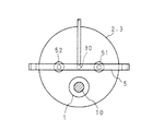
また研磨定盤2の上方には、前記保持台1と周方向に干渉せず、また前記ノズル30と上下方向に干渉しない位置に、該研磨定盤2の中心を通り、径方向に横切る態様に支持フレーム5が架設されており、該支持フレーム5には、前記研磨パッド3のドレッシング(目立て)を行うための第1のドレス用ヘッド51と第2のドレス用ヘッド52とが、前記研磨定盤2の中心部の両側に振り分け配置されている。
【0032】
第1,第2のドレス用ヘッド51,52は、共に円板形をなし、前記研磨定盤2の上面、即ち、研磨パッド3の表面に対し、夫々の下面(ドレス面)を平行に保って垂下支持されており、夫々の支軸回りに回転駆動されると共に、前記支持フレーム5に沿って研磨定盤2の径方向に移動し、また、研磨パッド3の表面に接離する方向に移動するように構成されている。
【0033】
図示の装置において、第1,第2のドレス用ヘッド51,52は、夫々のドレス面の粗さを異ならせ、後者のドレス面が前者のドレス面よりも粗くなるようにしてある。図3は、第1,第2のドレス用ヘッド51,52のドレス面の平面図であり、図示の如くドレス面は、その全面を周方向に扇形に分割して構成され、以下の如くにダイヤモンド粒が埋設された8か所のドレス部5a,5a…を備えている。
【0034】
図4は、前記ドレス部5aの一部を拡大して示す平面図である。図示の如くドレス部5aは、その面内の複数か所にダイヤモンド粒5b,5b…を埋設し、適宜の間隔にて千鳥配置して構成されている。これらのダイヤモンド粒5b,5b…の埋設は、電着、貼着等、ドレッシング時の抵抗に抗し得る強度が得られる適宜の手段により実現することができる。
【0035】
第1,第2のドレス用ヘッド51,52のドレス面の粗さは、夫々に埋設されたダイヤモンド粒5b,5b…の粒径dを変えることにより異ならせてある。第1のドレス用ヘッド51のドレス面は、各ドレス部5aに0.4mm以下の粒径を有するダイヤモンド粒5b,5b…を配して構成することができる。この場合第2のドレス用ヘッド52のドレス面は、第1のドレス用ヘッド51において用いたよりは大きい粒径を有するダイヤモンド粒5b,5b…を配することにより、第1のドレス用ヘッド51のドレス面よりも粗くしておく。
【0036】
また第2のドレス用ヘッド52のドレス面は、各ドレス部5aに0.2mm以上の粒径を有するダイヤモンド粒5b,5b…を配して構成することができる。この場合、第1のドレス用ヘッド51のドレス面は、第2のドレス用ヘッド52において用いたよりは小さい粒径を有するダイヤモンド粒5b,5b…を配し、第2のドレス用ヘッド52のドレス面よりも細かくしておく。
【0037】
なお、第1,第2のドレス用ヘッド51,52のドレス面の粗さの相違は、前述の如くダイヤモンド粒5b,5b…の粒径を変える手段に限らず、夫々のドレス部5aにおけるダイヤモンド粒5b,5b…の配設間隔を変える等、他の手段により実現することもできる。また以上の実施の形態においては、第1,第2のドレス用ヘッド51,52のドレス面を、周方向に8つのドレス部5a,5a…により分割構成してあるが、これよりも少ない分割、又はこれよりも多い分割によりドレス面を構成してもよい。更には、第1,第2のドレス用ヘッド51,52の下面全体を単一のドレス面により構成してもよい。
【0038】
以上の如き試料研磨装置による化学機械研磨は、図8に示す従来の装置におけると同様、前記保持台1及び研磨定盤2を回転させつつ相互に接近させて、図1中に2点鎖線により示す如く、保持台1の下面に保持された試料Wの研磨面(下面)を前記研磨パッド3の表面に押し当て、これら両面を、前記ノズル30から供給される研磨スラリを介して摺接せしめて行われ、試料Wの研磨面は、前記研磨スラリに含まれる研磨粒子の作用による機械的な研磨と、反応剤の作用による化学的な研磨とにより平坦化される。
【0039】
また研磨パッド3表面のドレッシング(目立て)は、前記第1のドレス用ヘッド51又は第2のドレス用ヘッド52と研磨定盤2とを回転させつつ相互に接近させて、図1中に2点鎖線により示す如く、研磨定盤2の上面に張着された研磨パッド3の表面に第1のドレス用ヘッド51又は第2のドレス用ヘッド52のドレス面を押し当て、これら両面を摺接せしめて行われる。なおこのとき、第1,第2のドレス用ヘッド51,52を、支持フレーム5に沿って半径方向に移動させることにより、研磨パッド3の表面全体のドレッシングを行わせることができる。
【0040】
このようなドレッシングは、前述の如く、研磨により均された研磨パッド3に対し、その表面性状を修復し、所望の研磨レートを回復させるために行われる一方、研磨定盤2に新たに張着された研磨パッド3に対し、該研磨パッド3を用いた研磨の開始前にその表面性状を安定化させるべく行われる。本発明において前記第1のドレス用ヘッド51と第2のドレス用ヘッド52とを備えたのは、これらを対象となる研磨パッド3の状態に応じて使い分け、前述した両場合の夫々において適正なドレッシングがなされるようにするためである。
【0041】
図5は、第1,第2のドレス用ヘッド51,52によるドレッシング量の時間的な変化の様子を示す図である。前述の如く細かいドレス面を有する第1のドレス用ヘッド51を用いた場合、図中に破線により示す如く、そのドレッシング量が時間の経過に伴って緩やかに増加する特性を示すのに対し、粗いドレス面を有する第2のドレス用ヘッドを用いた場合、図中に実線により示す如く、そのドレッシング量が、時間の経過に伴って急峻に増加する特性を示す。
【0042】
本発明においては、このようなドレッシング特性の相違を利用し、研磨に使用中の研磨パッド3を対象とする場合、必要なドレッシング量がわずかであることから、細かいドレス面を有し、ドレッシング量を抑えた第1のドレス用ヘッド51を用いる。これにより、ドレス時間の管理によって所望のドレッシング量が大きな誤差なく得られるようになり、研磨パッドの無用な損耗を抑えつつ、目的となる研磨レートの回復を確実に実現することができる。
【0043】
一方、研磨定盤2に新たに張着された使用前の研磨パッド3を対象とする場合には、必要となるドレッシング量が大きいことから、粗いドレス面を有し、大なるドレッシング量が得られる第2のドレス用ヘッド52を用いる。これにより、交換直後の新しい研磨パッド3の表面を短時間にて目立てし、研磨のために必要な表面性状を速やかに実現することができ、研磨パッド3の交換後、研磨を開始するまでの間の立ち上げ時間を可及的に短縮することが可能となる。このことは、試料研磨装置における研磨能率の向上に有用である。
【0044】
なお第1,第2のドレス用ヘッド51,52は、夫々単独にて用いるのではなく、適宜に組み合わせて用いてもよい。例えば、使用前の研磨パッド3のドレッシングに際し、第1,第2のドレス用ヘッド51,52の両方を用い、立ち上げ時間の更なる短縮を図るようにしてもよく、また、第2のドレス用ヘッド52による粗ドレッシングを所定時間行った後、第1のドレス用ヘッド51による仕上げドレッシングを行い、研磨開始前の研磨パッド3の表面に所望の性状を精度良く実現するようにしてもよい。
【0045】
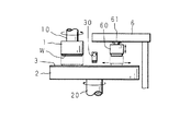
図6は、本発明に係る試料研磨方法の実施に用いる試料研磨装置の他の実施の形態の要部を模式的に示す側面図である。この試料研磨装置は、図1及び図8に示す試料研磨装置と同様に、試料Wを保持する保持台1と、研磨パッド3が張着された研磨定盤2と、研磨定盤2の中心上部に配された研磨スラリ供給用のノズル30とを備え、保持台1に保持された試料Wの下面を、前記ノズル30による研磨スラリの供給下にて研磨パッド3の上表面に押し当て、保持台1及び研磨定盤2の各別の支軸10,20回りの回転により摺接させて、前記試料Wの下面を化学機械研磨する構成としたものである。
【0046】
研磨定盤2の上方には、前記保持台1の配設位置と逆側の周縁部から中心部に向け、前記研磨定盤2の上面と平行をなして支持フレーム6が架設されており、該支持フレーム6には、研磨パッド3の表面をドレッシング(目立て)するための単一のドレス用ヘッド60が垂下支持されている。
【0047】
このドレス用ヘッド60は、図1に示す第1,第2のドレス用ヘッド51,52と同様、夫々の軸回りの回転が可能とされ、更に支持フレーム6に沿って研磨パッド3の半径方向への移動、及び研磨パッド3に対して接離する方向への移動が可能とされている。またドレス用ヘッド60の下面(ドレス面)は、前記図4及び図5に示す第1,第2のドレス用ヘッド51,52と同様、所定の粒径を有する複数のダイヤモンド粒を配して構成されている。
【0048】
以上の如く構成された試料研磨装置において、研磨パッド3表面のドレッシングは、前記ドレス用ヘッド60と研磨定盤2とを回転させつつ相互に接近させて、図中に2点鎖線により示す如く、ドレス用ヘッド60の下面(ドレス面)を研磨定盤2に張着された研磨パッド3の上表面に押し当て、更に、ドレス用ヘッド60を支持フレーム6に沿って半径方向に移動させることにより、研磨パッド3の全面に亘って行われる。
【0049】
ドレス用ヘッド60は、以上の如く行われるドレッシングに際し、研磨パッド3の上表面へのドレス面の押し当て面圧を変更する手段を備えており、研磨パッド3の状態に応じたドレッシングを、前記押し当て面圧を大小に変更することにより行わせる構成としてある。
【0050】
図7は、ドレス用ヘッド60及び面圧変更手段の構成を示す図である。本図中に断面視してあるように、ドレス用ヘッド60は、円筒形をなす外筒6aの内部に上下方向への摺動自在にピストン板6bを嵌装し、前記外筒6aの内部を上下のシリンダ室6c,6dに分割して空圧シリンダを構成する一方、前記ピストン板6bの下方に延設され、外筒6aの底壁を貫通するロッド6eの下端に、前述したドレス面をその下面に備えるドレス板6fを取付けて構成されている。
【0051】
外筒6aの上面に連設されたドレス用ヘッド60の回転軸61には、非回転状態に拘束された導圧リング62が外嵌されており、ピストン板6bの上下に構成されたシリンダ室6c,6dは、外筒6aの周壁に形成された導圧路63,64を介して前記導圧リング62の内面に周設された各別の導圧溝に連通させてある。前記導圧溝の夫々は、導圧リング62の外側に連通されており、この連通部に夫々連結された導圧管65,66により、面圧の発生源となるエアポンプPの吐出側に構成された電空レギュレータ(電圧・空圧変換手段)7に接続されている。
【0052】
電空レギュレータ7は、図示の如く、前記エアポンプPの吐出路70の中途に、固定絞り71及び可変絞り72をこの順に直列に介装して構成されており、前記導圧管65は、前記固定絞り71と可変絞り72との間に、また前記導圧管66は、前記可変絞り72の下流側に夫々接続されている。前記可変絞り72の絞り開度は、外部から与えられる開閉信号に応じて増減されるようになしてある。
【0053】
以上の構成により、導圧路63を介して前記導圧管65に連通する上部のシリンダ室6cと、導圧路64を介して前記導圧管66に連通する下部のシリンダ室6cとの間には、前記可変絞り72の前後の圧力差が発生し、この圧力差がピストン板6bに作用し、ロッド6eを介して前記ドレス板6fを下向きに押圧することとなり、該ドレス板6fの下面に構成されたドレス面は、この押圧力に対応する面圧にて研磨パッド3の表面に押し当てられてドレッシングが行われる。
【0054】
このとき、ドレス用ヘッド60の押し当て面圧の大小は、前記可変絞り72の前後に発生する圧力差の大小に対応し、この圧力差は、可変絞り72の絞り面積の減少に応じて大となる。また、押し当て面圧を変えてドレッシングを行った場合、前記図5と同様のドレッシング特性が得られ、押し当て面圧が小さい場合には、図中に破線により示す如く、時間の経過に伴って緩やかにドレッシング量が増加する特性を示すのに対し、押し当て面圧が大きい場合には、図中に実線により示す如く、時間の経過に伴ってドレッシング量が急峻に増加する特性を示す。このように、図7に示すドレス用ヘッド60を備える試料研磨装置においては、電空レギュレータ7の可変絞り72の絞り開度を変更することにより異なる特性下でのドレッシングを行わせることができる。
【0055】
而して、研磨に使用中の研磨パッド3を対象とする場合には、可変絞り72の絞り開度を大とし、小なる押し当て面圧下にてドレッシング量を抑えた状態でドレッシングを実施する。これにより、所望のドレッシング量が大きな誤差なく得られるようになり、研磨パッドの無用な損耗を抑えつつ研磨レートを確実に回復させることができる。また、研磨定盤2に新たに張着された研磨パッド3を対象とする場合には、可変絞り72の絞り開度を小とし、大なる押し当て面圧下にてドレッシングを実施する。これにより、交換直後の研磨パッド3を短時間にて目立てし、研磨のために必要な表面性状を速やかに実現することができ、立ち上げ時間を可及的に短縮することが可能となる。
【0056】
なお、可変絞り72の絞り開度を変更するために電空レギュレータ7に与える開閉信号は、オペレータによる手動操作により与える構成としてもよく、また、研磨工程の全体を管理するためのプロセス制御部から与える構成としてもよい。また押し当て面圧の変更手段は、以上の実施の形態に示す構成に限らず、適宜の構成にて実現することができる。
【0057】
【発明の効果】
以上詳述した如く本発明に係る試料研磨方法においては、使用中の研磨パッドに対して研磨レートの回復のためになされる通常のドレッシングを、相対的に細かいドレス面を有し、ドレッシング量を抑えた第1のドレス用ヘッドにより実施するから、研磨パッドの無用な損耗の防止と、研磨レートの確実な回復とを、比較的緩やかな時間管理下にて容易に実現することができ、また、研磨定盤に新たに張着された研磨パッドに対するドレッシングを、相対的に粗いドレス面を有し、ドレス量を高めた第2のドレス用ヘッドにより実施するから、このドレッシング後の研磨開始までの立ち上げ時間を短縮することができ、研磨作業全体の能率向上を達成し得る。
【0058】
また本発明に係る試料研磨装置においては、研磨パッド表面のドレッシングに用いるドレス用ヘッドとして、相対的に細かいドレス面を有し、ドレッシング量を抑えた第1のドレス用ヘッドと、相対的に粗いドレス面を有し、ドレス量を高めた第2のドレス用ヘッドとを備えたから、これら第1,第2のドレス用ヘッドを、研磨対象となる研磨パッドの状態に応じて使い分け、又は適宜に組み合わせて使用して前述した方法を実施することができ、研磨レートの回復のために使用中の研磨パッドに対してなされる通常のドレッシングを安定して行わせ、研磨パッドの無用な損耗を防ぎ、寿命の低下を未然に防止することができると共に、交換後の新しい研磨パッドのドレッシングに要する時間を短縮することができ、研磨作業全体の能率向上を達成し得る。
【0059】
また本発明の他の発明に係る試料研磨方法においては、使用中の研磨パッドに対して研磨レートの回復のためになされる通常のドレッシングを、ドレス用ヘッドの押し当て面圧を小とし、ドレッシング量を抑えた状態で実施するから、研磨パッドの無用な損耗の防止と、研磨レートの確実な回復とを、比較的緩やかな時間管理下にて容易に実現することができ、また、研磨定盤に新たに張着された研磨パッドの表面のドレッシングを、ドレス用ヘッドの押し当て面圧を大とし、ドレッシング量を高めた状態で実施するから、このドレッシング後の研磨開始までの立ち上げ時間を短縮することができ、研磨作業全体の能率向上を達成し得る。
【0060】
更に本発明の他の発明に係る試料研磨装置においては、研磨パッド表面のドレッシングに用いるドレス用ヘッドに面圧変更手段を付設したから、研磨対象となる研磨パッドの状態に応じてドレス用ヘッドの押し当て面圧を変更することにより、目的に応じたドレッシング量が得られ、前述した方法を実施することが可能となり、研磨レートの回復のために使用中の研磨パッドに対してなされる通常のドレッシングを安定して行わせ、研磨パッドの無用な損耗を防ぎ、寿命の低下を未然に防止することができると共に、交換後の新しい研磨パッドのドレッシングに要する時間を短縮し、研磨能率の向上に寄与することができる等、本発明は優れた効果を奏する。
【図面の簡単な説明】
【図1】本発明に係る試料研磨装置の実施に使用する試料研磨装置の要部の構成を模式的に示す側面図である。
【図2】図1に示す試料研磨装置を上方から見た平面図である。
【図3】第1,第2のドレス用ヘッドのドレス面の平面図である。
【図4】ドレス部の一部を拡大して示す平面図である。
【図5】第1,第2のドレス用ヘッドによるドレッシング量の時間的な変化の様子を示す図である。
【図6】本発明に係る試料研磨方法の実施に用いる試料研磨装置の他の実施の形態の要部を模式的に示す側面図である。
【図7】図6に示す試料研磨装置に用いられているドレス用ヘッド及び面圧変更手段の構成を示す図である。
【図8】従来の試料研磨装置の要部の構成を模式的に示す側面図である。
【符号の説明】
1 保持台
2 研磨定盤
3 研磨パッド
5a ドレス部
5b ダイヤモンド粒
6a 外筒
6b ピストン板
6c シリンダ室
6d シリンダ室
7 電空レギュレータ
51 第1のドレス用ヘッド
52 第2のドレス用ヘッド
60 ドレス用ヘッド[0001]
BACKGROUND OF THE INVENTION
The present invention relates to a sample polishing method for polishing one surface of a sample such as a semiconductor substrate, and an apparatus used for carrying out this method.
[0002]
[Prior art]
A lamination process in which a conductor layer, a semiconductor layer, or an insulator layer is laminated on the surface of a semiconductor substrate such as a silicon substrate, and a pattern formation process in which a circuit pattern is formed on the surface of each laminated layer are repeated. In manufacturing a semiconductor device, the surface is polished and flattened so as not to hinder the formation of a circuit pattern on the surface of each layer obtained in the stacking step.
[0003]
In recent years, chemical mechanical polishing has been widely adopted as a polishing method for satisfactorily polishing the surface of such a semiconductor substrate. FIG. 8 is a side view schematically showing a configuration of a main part of a sample polishing apparatus conventionally used for the chemical mechanical polishing as described above. This sample polishing apparatus includes a holding table 1 that holds a sample W such as a semiconductor substrate to be polished on its lower surface by, for example, vacuum suction, and a
[0004]
The holding table 1 and the
[0005]
A
[0006]
In the chemical mechanical polishing using the sample polishing apparatus as described above, the holding table 1 for holding the sample W is positioned on a predetermined circumference on the upper surface of the
[0007]
In the chemical mechanical polishing performed in this way, the surface properties of the
[0008]
The dressing by the
[0009]
The dress surface of the
[0010]
[Problems to be solved by the invention]
In the sample polishing apparatus as described above, the
[0011]
However, the
[0012]
However, the dressing for the
[0013]
In order to shorten the dressing time, it is effective to use a dressing head having a rough dress surface and increase the dressing amount per unit time. However, when a dressing head having a rough dressing surface is used, it is difficult to manage the time during the above-described normal dressing, the dressing amount is likely to be excessive or insufficient, and the desired dressing effect may not be obtained due to insufficient dressing. On the contrary, there is a problem that excessive dressing is performed, and the amount of wear of the
[0014]
The present invention has been made in view of such circumstances, and reduces the dressing time at the time of replacement of the polishing pad, and provides a normal dressing performed on the polishing pad in use for recovery of the polishing rate. It is an object of the present invention to provide a sample polishing method and a sample polishing apparatus that can be stably performed.
[0015]
[Means for Solving the Problems]
In the sample polishing method according to the present invention, one surface of a sample held on a sample stage is pressed against the surface of a polishing pad that is stuck to a polishing surface plate, and the sample is slidably contacted while supplying a polishing slurry therebetween. In the sample polishing method for dressing the surface by pressing the dressing surface of the dressing head against the surface of the polishing pad while polishing one surface of the polishing pad, first and second dressing heads having dressing surfaces with different roughnesses The dressing of the surface of the polishing pad that has been leveled by polishing is carried out by the first head for dressing having a relatively fine dress surface and is newly attached to the polishing surface plate. Is implemented by a second dressing head having a relatively rough dressing surface.
[0016]
In the present invention, a first dress head having a relatively fine dress surface and a reduced dressing amount, and a second dress head having a relatively rough dress surface and an increased dressing amount, When dressing the surface of the polishing pad leveled by polishing, the first dressing head is used, and this dressing is performed stably to reduce the wear of the polishing pad and recover the target polishing rate. On the other hand, the dressing of the surface of the polishing pad newly attached to the polishing surface plate is carried out using a second dressing head having a relatively rough dressing surface and increasing the dressing amount. Shorten the time required for dressing and improve the efficiency of polishing work.
[0017]
Further, the dressing by the first dress head is also performed on a polishing pad during polishing of the sample.
[0018]
In the present invention, dressing by the first dressing head on the surface of the polishing pad in use is performed at a position different from this polishing position during polishing of the sample by the polishing pad, and the dressing time is separately set. A stable polishing rate is always obtained without providing it.
[0019]
Also,The sample polishing apparatus according to the present invention comprises:In a sample polishing apparatus for polishing one surface of a sample held on a sample table against the surface of a polishing pad that is stuck to a polishing surface plate, the surface is pressed against the surface of the polishing pad. The first dressing head and the second dressing head for performing dressing are provided, and the second dressing head has a rough dress surface as compared with the first dressing head.It is characterized by that.
Further, in the sample polishing apparatus according to the present invention, one surface of the sample held on the sample table is pressed against the surface of the polishing pad attached to the polishing surface plate to polish one surface of the sample, A first dressing head for dressing the surface of a polishing pad leveled by polishing in a sample polishing apparatus that presses the dress surface of a dressing head against the surface and dresses the surface, and the first dressing head And a second dressing head for dressing the surface of the polishing pad newly attached to the polishing surface plate.
[0020]
In the present invention, a first dress head having a relatively fine dress surface and a reduced dressing amount, and a second dress head having a relatively rough dress surface and an increased dressing amount, By using these properly or in combination, the dressing amount according to the purpose can be obtained, the time required for dressing a new polishing pad after replacement is shortened, and polishing in use Regular dressing for the pad is performed stably.
[0021]
The dressing surface of the first dressing head is characterized in that diamond grains having a grain size of 0.4 mm or less are embedded in a base material.
[0022]
The dressing surface of the first dressing head has a structure in which diamond grains having a grain size of 0.4 mm or less are embedded in a resin or metal base material, so that the dressing head is mainly used. The normal dressing for the polishing pad is stably performed. At this time, the dress surface of the second dress head is configured by embedding diamond grains having a grain size larger than the diamond grains used for the dress face of the first dress head in a similar base material.
[0023]
The dressing surface of the second dressing head is characterized in that diamond grains having a grain size of 0.2 mm or more are embedded in a base material.
[0024]
The dressing surface of the second dressing head has a structure in which diamond grains having a grain size of 0.2 mm or less are embedded in a resin or metal base material, so that a polishing pad mainly using this dressing head is used. Reduce the time required for dressing at start-up to such an extent that there is no practical problem. At this time, the dress surface of the first dress head is formed by embedding diamond grains having a grain size smaller than that used for the dress face of the second dress head in the same base material.
[0025]
A sample polishing method according to another invention of the present invention is a method in which one surface of a sample held on a sample table is pressed against the surface of a polishing pad attached to a polishing surface plate, and a sliding slurry is supplied while supplying a polishing slurry therebetween. In the sample polishing method of dressing the surface by pressing a dressing surface of a dressing head against the surface of the polishing pad while polishing one surface of the sample in contact with the surface of the polishing pad, The dressing of the surface of the polishing pad newly attached to the polishing surface plate is performed by changing the pressing surface pressure of the dress surface of the dress head to a large or small.
[0026]
In the present invention, the dressing of the surface of the polishing pad leveled by polishing is carried out in a state in which the pressure of the dressing surface pressed against the surface of the polishing pad is reduced and the dressing amount is suppressed, and the wear of the polishing pad is reduced. The target polishing rate can be recovered while suppressing the above. In addition, the dressing of the surface of the polishing pad newly attached to the polishing surface plate is carried out with the dressing surface pressed against the surface of the polishing pad to increase the dressing amount. To improve the efficiency of polishing work.
[0027]
Also,Main departureClearlySample polishingapparatusIsIn a sample polishing apparatus that polishes one surface of a sample held on a sample table against the surface of a polishing pad that is stuck to a polishing surface plate, the dress surface is pressed against the surface of the polishing pad. A dressing head for dressing the surface; and a surface pressure changing means attached to the dressing head for changing the pressing surface pressure of the dress surface to a large or small.It is characterized by that.
Furthermore, the sample polishing apparatus according to the present invention is a sample polishing apparatus for pressing one surface of a sample held on a sample table against a surface of a polishing pad attached to a polishing surface plate, and polishing one surface of the sample. The surface of the polishing pad in which the dressing surface is pressed against the surface of the polishing pad, the dressing amount for dressing the surface, and the dressing amount with respect to the surface of the polishing pad leveled by polishing is newly attached to the polishing surface plate And a means for changing the pressing surface pressure of the dressing surface so as to be suppressed compared to the dressing amount with respect to.
[0028]
In this invention, the surface pressure changing means is attached to the head for dressing, and by the operation of the means, the pressing surface pressure of the dress surface against the polishing pad is changed by the operation of the surface pressure changing means. It is possible to obtain a suitable dressing amount, to shorten the time required for dressing a new polishing pad after replacement, and to stably perform normal dressing on the polishing pad in use.
[0029]
DETAILED DESCRIPTION OF THE INVENTION
Hereinafter, the present invention will be described in detail with reference to the drawings illustrating embodiments thereof. FIG. 1 is a side view schematically showing a configuration of a main part of a sample polishing apparatus used for carrying out a sample polishing method according to the present invention, and FIG. 2 is a plan view of the sample polishing apparatus as viewed from above. Like the conventional sample polishing apparatus shown in FIG. 8, this sample polishing apparatus has a thick disk-shaped holding table 1 that holds a sample W to be polished on its lower surface, and an upper surface on the lower surface of the holding table 1. And a disk-shaped
[0030]
The holding table 1 and the polishing
[0031]
Further, above the polishing
[0032]
Both the first and second dress heads 51 and 52 have a disk shape, and keep their lower surfaces (dress surfaces) parallel to the upper surface of the polishing
[0033]
In the illustrated apparatus, the first and second dress heads 51 and 52 have different dress surface roughnesses so that the latter dress surface is rougher than the former dress surface. FIG. 3 is a plan view of the dress surface of the first and second dress heads 51 and 52. As shown in the figure, the dress surface is formed by dividing the entire surface into a sector shape in the circumferential direction. Eight dressed parts 5a, 5a ... with diamond grains embedded.
[0034]
FIG. 4 is an enlarged plan view showing a part of the dress portion 5a. As shown in the figure, the dress portion 5a is configured by embedding
[0035]
The roughness of the dress surfaces of the first and second dress heads 51 and 52 is varied by changing the grain size d of the
[0036]
Further, the dress surface of the
[0037]
The difference in the roughness of the dress surfaces of the first and second dress heads 51, 52 is not limited to the means for changing the grain size of the
[0038]
In the chemical mechanical polishing using the sample polishing apparatus as described above, as in the conventional apparatus shown in FIG. 8, the holding table 1 and the polishing
[0039]
In addition, dressing (sharpening) of the surface of the
[0040]
Such dressing is performed to repair the surface properties of the
[0041]
FIG. 5 is a diagram showing a temporal change in the dressing amount by the first and second dress heads 51 and 52. As described above, when the
[0042]
In the present invention, when such a difference in dressing characteristics is used and the
[0043]
On the other hand, when the
[0044]
The first and second dress heads 51 and 52 may be used in an appropriate combination instead of being used alone. For example, when dressing the
[0045]
FIG. 6 is a side view schematically showing a main part of another embodiment of the sample polishing apparatus used for carrying out the sample polishing method according to the present invention. This sample polishing apparatus is similar to the sample polishing apparatus shown in FIGS. 1 and 8, the holding table 1 holding the sample W, the polishing
[0046]
Above the polishing
[0047]
The
[0048]
In the sample polishing apparatus configured as described above, the dressing on the surface of the
[0049]
The dressing
[0050]
FIG. 7 is a diagram showing the configuration of the
[0051]
A
[0052]
As shown in the figure, the
[0053]
With the above configuration, there is a gap between the upper cylinder chamber 6c communicating with the
[0054]
At this time, the magnitude of the pressing surface pressure of the dressing
[0055]
Thus, when the
[0056]
Note that the open / close signal given to the
[0057]
【The invention's effect】
As described above in detail, in the sample polishing method according to the present invention, the normal dressing made for recovery of the polishing rate with respect to the polishing pad in use has a relatively fine dress surface, and the dressing amount is reduced. Since the first head for dressing is performed, prevention of unnecessary wear of the polishing pad and reliable recovery of the polishing rate can be easily realized under relatively gradual time management. Since the dressing for the polishing pad newly attached to the polishing surface plate is carried out by the second dress head having a relatively rough dress surface and an increased dressing amount, the polishing after this dressing starts The start-up time can be shortened, and the efficiency of the entire polishing operation can be improved.
[0058]
In the sample polishing apparatus according to the present invention, the dressing head used for dressing the polishing pad surface is relatively rough with the first dressing head having a relatively fine dress surface and a reduced dressing amount. Since the second dressing head having a dress surface and an increased dressing amount is provided, the first and second dressing heads are selectively used according to the state of the polishing pad to be polished, or appropriately. Can be used in combination to perform the method described above, ensuring stable dressing on the polishing pad in use to recover the polishing rate and preventing unnecessary wear of the polishing pad In addition to preventing a decrease in service life, the time required for dressing a new polishing pad after replacement can be shortened, improving the efficiency of the entire polishing operation. It can be achieved.
[0059]
In the sample polishing method according to another invention of the present invention, the normal dressing performed for recovering the polishing rate with respect to the polishing pad in use is performed, the pressing surface pressure of the dressing head is reduced, and the dressing is performed. Since the amount is reduced, it is possible to easily prevent unnecessary wear of the polishing pad and to reliably recover the polishing rate under relatively gradual time management. Since the dressing of the surface of the polishing pad newly attached to the board is performed in a state in which the pressing surface pressure of the dressing head is increased and the dressing amount is increased, the start-up time until the start of polishing after this dressing Thus, the efficiency of the entire polishing operation can be improved.
[0060]
Further, in the sample polishing apparatus according to another invention of the present invention, the dressing head used for dressing the polishing pad surface is provided with the surface pressure changing means, so that the dressing head is in accordance with the state of the polishing pad to be polished. By changing the pressing surface pressure, a dressing amount corresponding to the purpose can be obtained, and it becomes possible to carry out the above-described method, which is usually performed for a polishing pad in use for recovering the polishing rate. Stable dressing prevents unnecessary wear of the polishing pad, prevents a decrease in service life, shortens the time required for dressing a new polishing pad after replacement, and improves polishing efficiency The present invention has excellent effects, such as being able to contribute.
[Brief description of the drawings]
FIG. 1 is a side view schematically showing a configuration of a main part of a sample polishing apparatus used for implementing a sample polishing apparatus according to the present invention.
FIG. 2 is a plan view of the sample polishing apparatus shown in FIG. 1 as viewed from above.
FIG. 3 is a plan view of a dress surface of first and second dress heads.
FIG. 4 is an enlarged plan view showing a part of a dress portion.
FIG. 5 is a diagram illustrating a temporal change in the dressing amount by the first and second dressing heads.
FIG. 6 is a side view schematically showing a main part of another embodiment of a sample polishing apparatus used for carrying out a sample polishing method according to the present invention.
7 is a diagram showing a configuration of a dressing head and a surface pressure changing unit used in the sample polishing apparatus shown in FIG. 6;
FIG. 8 is a side view schematically showing a configuration of a main part of a conventional sample polishing apparatus.
[Explanation of symbols]
1 Holding stand
2 Polishing surface plate
3 Polishing pad
5a Dress part
5b diamond grains
6a outer cylinder
6b Piston plate
6c Cylinder chamber
6d cylinder chamber
7 Electro-pneumatic regulator
51 First dress head
52 Second dress head
60 Head for dress
Claims (9)
粗さの異なるドレス面を有する第1,第2のドレス用ヘッドを用い、研磨により均された研磨パッドの表面のドレッシングを、相対的に細かいドレス面を有する第1のドレス用ヘッドにより実施し、
研磨定盤に新たに張着された研磨パッドの表面のドレッシングを、相対的に粗いドレス面を有する第2のドレス用ヘッドにより実施することを特徴とする試料研磨方法。While pressing one surface of the sample held on the sample table against the surface of the polishing pad stuck to the polishing surface plate, the surface of the sample is polished by being brought into sliding contact while supplying a polishing slurry therebetween, while the polishing In the sample polishing method of pressing the dress surface of the dress head against the surface of the pad and dressing the surface,
Using the first and second dress heads having dress surfaces with different roughnesses, the dressing of the surface of the polishing pad leveled by polishing is performed by the first dress head having a relatively fine dress surface. ,
A sample polishing method, wherein dressing of the surface of a polishing pad newly attached to a polishing surface plate is performed by a second dress head having a relatively rough dress surface.
前記研磨パッドの表面に押し当てられて該表面のドレッシングを行う第1のドレス用ヘッド及び第2のドレス用ヘッドを備え、
該第2のドレス用ヘッドは、前記第1のドレス用ヘッドに比べて粗いドレス面を有することを特徴とする試料研磨装置。 In a sample polishing apparatus for pressing one surface of a sample held on a sample table against the surface of a polishing pad attached to a polishing surface plate and polishing one surface of the sample,
A first dressing head and a second dressing head which are pressed against the surface of the polishing pad to perform dressing on the surface;
The sample polishing apparatus , wherein the second dress head has a rough dress surface as compared with the first dress head .
研磨により均された研磨パッドの表面のドレッシングを行う第1のドレス用ヘッドと、 A first dressing head for dressing the surface of the polishing pad leveled by polishing;
該第1のドレス用ヘッドに比べて粗いドレス面を有し、研磨定盤に新たに張着された研磨パッドの表面のドレッシングを行う第2のドレス用ヘッドと A second dressing head having a rough dress surface compared to the first dressing head and performing dressing on the surface of the polishing pad newly attached to the polishing surface plate;
を備えることを特徴とする試料研磨装置。 A sample polishing apparatus comprising:
研磨により均された研磨パッドの表面のドレッシングと、研磨定盤に新たに張着された研磨パッドの表面のドレッシングとを、前記ドレス用ヘッドのドレス面の押し当て面圧を大小に変更して実施することを特徴とする試料研磨方法。While pressing one surface of the sample held on the sample table against the surface of the polishing pad stuck to the polishing surface plate, the surface of the sample is polished by being brought into sliding contact while supplying a polishing slurry therebetween, while the polishing In the sample polishing method of pressing the dress surface of the dress head against the surface of the pad and dressing the surface,
The dressing on the surface of the polishing pad leveled by polishing and the dressing on the surface of the polishing pad newly attached to the polishing surface plate are changed to a large or small pressure on the dressing surface of the dress head. A method for polishing a sample, comprising:
前記研磨パッドの表面にそのドレス面を押し当て、前記表面をドレッシングするドレス用ヘッドと、 A dress head for pressing the dress surface against the surface of the polishing pad and dressing the surface;
該ドレス用ヘッドに付設され、前記ドレス面の押し当て面圧を大小に変更する面圧変更手段と A surface pressure changing means attached to the dress head for changing the pressing surface pressure of the dress surface to a large or small;
を備えることを特徴とする試料研磨装置。 A sample polishing apparatus comprising:
前記研磨パッドの表面にそのドレス面を押し当て、前記表面をドレッシングするドレス用ヘッドと、 A dress head for pressing the dress surface against the surface of the polishing pad and dressing the surface;
研磨により均された研磨パッドの表面に対するドレッシング量が、研磨定盤に新たに張 The amount of dressing on the surface of the polishing pad that has been leveled by polishing is newly applied to the polishing surface plate 着された研磨パッドの表面に対するドレッシング量に比べて抑えた状態になるように、ドレス面の押し当て面圧を変更する手段とMeans for changing the pressing surface pressure of the dress surface so that the dressing amount against the surface of the worn polishing pad is suppressed.
を備えることを特徴とする試料研磨装置。 A sample polishing apparatus comprising:
Priority Applications (1)
| Application Number | Priority Date | Filing Date | Title |
|---|---|---|---|
| JP15573699A JP3945940B2 (en) | 1999-06-02 | 1999-06-02 | Sample polishing method and sample polishing apparatus |
Applications Claiming Priority (1)
| Application Number | Priority Date | Filing Date | Title |
|---|---|---|---|
| JP15573699A JP3945940B2 (en) | 1999-06-02 | 1999-06-02 | Sample polishing method and sample polishing apparatus |
Publications (3)
| Publication Number | Publication Date |
|---|---|
| JP2000343406A JP2000343406A (en) | 2000-12-12 |
| JP2000343406A5 JP2000343406A5 (en) | 2005-11-24 |
| JP3945940B2 true JP3945940B2 (en) | 2007-07-18 |
Family
ID=15612333
Family Applications (1)
| Application Number | Title | Priority Date | Filing Date |
|---|---|---|---|
| JP15573699A Expired - Fee Related JP3945940B2 (en) | 1999-06-02 | 1999-06-02 | Sample polishing method and sample polishing apparatus |
Country Status (1)
| Country | Link |
|---|---|
| JP (1) | JP3945940B2 (en) |
Families Citing this family (5)
| Publication number | Priority date | Publication date | Assignee | Title |
|---|---|---|---|---|
| JP4072810B2 (en) | 2001-01-19 | 2008-04-09 | 株式会社荏原製作所 | Dressing apparatus and polishing apparatus provided with the dressing apparatus |
| JP5390750B2 (en) * | 2007-03-30 | 2014-01-15 | ラムバス・インコーポレーテッド | Polishing apparatus and polishing pad regeneration processing method |
| JP5444596B2 (en) * | 2007-08-31 | 2014-03-19 | 富士通セミコンダクター株式会社 | Manufacturing method of semiconductor device |
| KR100930390B1 (en) * | 2008-03-27 | 2009-12-08 | 주식회사 하이닉스반도체 | Chemical mechanical polishing equipment |
| CN110744450B (en) * | 2019-10-21 | 2021-11-26 | 西安奕斯伟材料科技有限公司 | Dresser and dressing method for polishing pad |
Family Cites Families (5)
| Publication number | Priority date | Publication date | Assignee | Title |
|---|---|---|---|---|
| JPH0631945U (en) * | 1992-09-25 | 1994-04-26 | シチズン時計株式会社 | Polishing surface plate correction tool |
| JPH091457A (en) * | 1995-06-19 | 1997-01-07 | Sony Corp | Wheel dresser |
| JP3360488B2 (en) * | 1995-06-20 | 2002-12-24 | ソニー株式会社 | Polishing apparatus and polishing method using the same |
| JP3482321B2 (en) * | 1996-10-15 | 2003-12-22 | 新日本製鐵株式会社 | Dresser for polishing cloth for semiconductor substrate and method of manufacturing the same |
| JP3660448B2 (en) * | 1996-11-13 | 2005-06-15 | 株式会社日立製作所 | Semiconductor device manufacturing method and manufacturing apparatus |
-
1999
- 1999-06-02 JP JP15573699A patent/JP3945940B2/en not_active Expired - Fee Related
Also Published As
| Publication number | Publication date |
|---|---|
| JP2000343406A (en) | 2000-12-12 |
Similar Documents
| Publication | Publication Date | Title |
|---|---|---|
| US6537190B2 (en) | Method and apparatus for mechanical and chemical-mechanical planarization of microelectronic substrates | |
| US7052375B2 (en) | Method of making carrier head backing plate having low-friction coating | |
| US7156727B2 (en) | Web-format polishing pads and methods for manufacturing and using web-format polishing pads in mechanical and chemical-mechanical planarization of microelectronic substrates | |
| JP3823086B2 (en) | Polishing pad and polishing method | |
| US8021566B2 (en) | Method for pre-conditioning CMP polishing pad | |
| JP3076291B2 (en) | Polishing equipment | |
| US6905400B2 (en) | Method and apparatus for dressing polishing cloth | |
| JPH07256554A (en) | Truing device for wafer polishing pad | |
| KR100525652B1 (en) | Polishing apparatus | |
| JP2002515833A (en) | Polishing media magazine for improved polishing | |
| JP2004001152A (en) | Dresser, dressing method, polishing device, and polishing method | |
| KR100832768B1 (en) | Wafer polishing apparatus and method for polishing wafers | |
| JP3945940B2 (en) | Sample polishing method and sample polishing apparatus | |
| US6648731B2 (en) | Polishing pad conditioning apparatus in chemical mechanical polishing apparatus | |
| JP2003179017A (en) | Polisher and polishing pad dressing method therein | |
| KR20030067674A (en) | Web-style pad conditioning system and methods for implementing the same | |
| JP3640504B2 (en) | Dressing method and apparatus | |
| US6780095B1 (en) | Method and apparatus for mechanical and chemical-mechanical planarization of microelectronic substrates | |
| WO2008082056A1 (en) | Diamond tool and method for manufacturing the same | |
| JP2000153445A (en) | Dresser for polishing device | |
| US20030220051A1 (en) | Conditioning disk actuating system | |
| JP2001038602A (en) | Polishing device | |
| JP2003170346A (en) | Dressing device of polishing pad and polishing device with dressing device | |
| JP2004017214A (en) | Pad conditioning device, pad conditioning method, and polishing device | |
| US20030220049A1 (en) | Conditioning disk actuating system |
Legal Events
| Date | Code | Title | Description |
|---|---|---|---|
| A521 | Written amendment |
Free format text: JAPANESE INTERMEDIATE CODE: A523 Effective date: 20051007 |
|
| A621 | Written request for application examination |
Free format text: JAPANESE INTERMEDIATE CODE: A621 Effective date: 20051007 |
|
| A977 | Report on retrieval |
Free format text: JAPANESE INTERMEDIATE CODE: A971007 Effective date: 20070406 |
|
| TRDD | Decision of grant or rejection written | ||
| A01 | Written decision to grant a patent or to grant a registration (utility model) |
Free format text: JAPANESE INTERMEDIATE CODE: A01 Effective date: 20070410 |
|
| A61 | First payment of annual fees (during grant procedure) |
Free format text: JAPANESE INTERMEDIATE CODE: A61 Effective date: 20070410 |
|
| R150 | Certificate of patent or registration of utility model |
Free format text: JAPANESE INTERMEDIATE CODE: R150 |
|
| LAPS | Cancellation because of no payment of annual fees |