JP3944927B2 - Ball screw type linear actuator - Google Patents

Ball screw type linear actuator Download PDF

Info

Publication number
JP3944927B2
JP3944927B2 JP26320296A JP26320296A JP3944927B2 JP 3944927 B2 JP3944927 B2 JP 3944927B2 JP 26320296 A JP26320296 A JP 26320296A JP 26320296 A JP26320296 A JP 26320296A JP 3944927 B2 JP3944927 B2 JP 3944927B2
Authority
JP
Japan
Prior art keywords
gear member
ball nut
peripheral surface
outer peripheral
pair
Prior art date
Legal status (The legal status is an assumption and is not a legal conclusion. Google has not performed a legal analysis and makes no representation as to the accuracy of the status listed.)
Expired - Fee Related
Application number
JP26320296A
Other languages
Japanese (ja)
Other versions
JPH10110800A (en
Inventor
幹雄 山口
浩信 塩野
Current Assignee (The listed assignees may be inaccurate. Google has not performed a legal analysis and makes no representation or warranty as to the accuracy of the list.)
NSK Ltd
Original Assignee
NSK Ltd
Priority date (The priority date is an assumption and is not a legal conclusion. Google has not performed a legal analysis and makes no representation as to the accuracy of the date listed.)
Filing date
Publication date
Application filed by NSK Ltd filed Critical NSK Ltd
Priority to JP26320296A priority Critical patent/JP3944927B2/en
Publication of JPH10110800A publication Critical patent/JPH10110800A/en
Application granted granted Critical
Publication of JP3944927B2 publication Critical patent/JP3944927B2/en
Anticipated expiration legal-status Critical
Expired - Fee Related legal-status Critical Current

Links

Images

Description

【0001】
【発明の属する技術分野】
この発明に係るボールねじ式リニアアクチュエータは、重量物を持ち上げる為のジャッキとして、或は各種機械装置に組み込んで小さな入力トルクから大きな直線運動方向の出力を得る動力変換装置として、それぞれ利用できる。
【0002】
【従来の技術】
ジャッキ等として使用できるボールねじ式リニアアクチュエータとして従来から、例えば実開昭63−53058号公報等に記載されたものが知られている。図5〜6は、この公報に記載された構造とは若干異なるが、従来から使用されているボールねじ式リニアアクチュエータの要部を示している。このボールねじ式リニアアクチュエータ1は、図示しない電動モータにより減速機構2を介してボールナット3を回転駆動し、このボールナット3の回転をボールねじ軸4の直線運動に変換するものである。
【0003】
上記減速機構2は、回転方向の変換自在な図示しない電動モータにより回転駆動される入力軸に固定したウォーム5と、このウォーム5と噛合した、ギヤ部材であるウォームホイール6とから成る。又、上記ボールねじ軸4の外周面には、断面円弧形の第一螺旋溝7を、上記ボールナット3の内周面には、やはり断面円弧形の第二螺旋溝8を、それぞれ形成している。そして、これら第一螺旋溝7と第二螺旋溝8との間に複数のボール9、9を転動自在に設けて、上記ボールナット3の回転を上記ボールねじ軸4の直線運動に変換する為のボールねじ機構を構成している。尚、ボールねじ式リニアアクチュエータ1の使用時には、上記ボールねじ軸4の端部は非駆動部に結合する為、このボールねじ軸4が回転する事はない。
【0004】
又、上記ボールナット3の一部外周面に形成した第一平坦面12には、それぞれが上記ボール9、9を通過させる為の、1対の送り孔の端部を開口させている。そして、これら両送り孔の端部開口同士を循環チューブにより連通させて、上記第二螺旋溝8の一端部にまで移動したボール9、9をこの第二螺旋溝8の他端部に戻し、これら複数のボール9、9を循環させる為の循環機構を構成している。
【0005】
上記ボールナット3とウォームホイール6とは、互いの相対回転を不能として、軸方向に亙って互いに直列に、且つ同心に結合している。即ち、上記ボールナット3の一端部(図5〜6の右端部)に内側円筒部10を、上記ウォームホイール6の一端部(図5〜6の左端部)に外側円筒部11を、それぞれ形成し、この外側円筒部11に上記内側円筒部10を、がたつきなく内嵌している。又、上記ボールナット3の外周面で、上記内側円筒部10よりも軸方向中央寄り部分には、互いに平行な1対の第二平坦面13、13を形成している。一方、上記ウォームホイール6の一端面(図5〜6の左端面)には1対の突壁14、14を形成し、これら両突壁14、14の内周側面を、互いに平行な1対の第三平坦面15、15としている。これら第三平坦面15、15同士の間隔は、上記第二平坦面13、13同士の間隔と同じか僅かに大きくしている。従って、上記内側、外側両円筒部10、11同士を嵌合させた状態でこれら第二、第三平坦面13、15同士が係合し、上記ボールナット3とウォームホイール6との相対回転を不能にする。上述の様に組み合わされたボールナット3とウォームホイール6とは、ケーシング16の内側に、1対の転がり軸受17、17により、回転自在に支承している。
【0006】
上述の様に構成されるボールねじ式リニアアクチュエータ1の使用時には、電動モータを回転させる事により、前記ウォーム5を介して上記ウォームホイール6及びボールナット3を所望方向に回転させる。この結果、このボールナット3と複数のボール9、9を介して螺合したボールねじ軸4が軸方向に変位する。
【0007】
上述した従来構造の第1例の場合には、ボールナット3とウォームホイール6とを軸方向に亙り直列に結合している。これに対して、図7に示す様に、ボールナット3aの周囲にウォームホイール6aを固設する構造も、従来から知られている。この従来構造の第2例の場合には、上記ボールナット3aに対する上記ウォームホイール6aの回転防止を図る為に、上記ボールナット3aの外周面及びウォームホイール6aの内周面にキー溝18、19を形成している。そして、これらキー溝18、19に掛け渡す状態でキー20を設け、上記ボールナット3aとウォームホイール6aとを同期して回転自在としている。
【0008】
【発明が解決しようとする課題】
図5〜6に示した従来構造の第1例の場合には、ボールナット3とウォームホイール6とを軸方向に亙り直列に結合している為、軸方向に亙る長さが大きくなる事が避けられず、ボールねじ式リニアアクチュエータ1の長さ寸法が大きくなる。又、図7に示した従来構造の第2例の場合には、ウォームホイール6aの内側にキー20を設ける必要上、ボールナット3aとウォームホイール6aとの厚さ寸法が大きくなり、ボールねじ式アクチュエータ直径が大きくなる。
本発明は、この様な事情に鑑みて、長さ並びに直径を小さくして、小型のボールねじ式リニアアクチュエータを提供すべく発明したものである。
【0009】
【課題を解決するための手段】
本発明のボールねじ式リニアアクチュエータは、何れも、前述した従来のボールねじ式リニアアクチュエータと同様に、外周面に断面円弧形の第一螺旋溝を形成したボールねじ軸と、内周面に断面円弧形の第二螺旋溝を形成したボールナットと、上記第一螺旋溝と上記第二螺旋溝との間に転動自在に設けた複数のボールと、これら複数のボールを循環させる為の循環機構と、上記ボールナットに外嵌する円筒部及びこの円筒部の(請求項2、3に記載した発明の場合は、中間部)外周面に固設したギヤを有するギヤ部材と、このギヤ部材を含んで構成され、入力軸の回転に伴って上記ギヤ部材を回転させる減速機構とを備える。
特に、本発明のうちの請求項1に記載したボールねじ式リニアアクチュエータに於いては、上記ボールナットの軸方向端部に設けた外向フランジ状の鍔部の外周縁から径方向内方に凹む状態で形成した1対の切り欠きと、上記ボールナットの外周面のうちでこれら両切り欠きに整合する位置にこのボールナットの全長に亙って形成された1対の凹溝と、上記ギヤ部材の軸方向端部に、上記1対の切り欠きと同じ位相で形成した、それぞれがこのギヤ部材の軸方向及び径方向内方に突出する1対の突起とを備える。そして、上記ギヤ部材を上記ボールナットに、上記両突起の内径側端部と上記両凹溝とを係合させつつこのギヤ部材をこのボールナットに外嵌し、このボールナットの外周面で上記小径部の両側部分とこのギヤ部材の内周面とを締り嵌めで嵌合させた状態で上記1対の突起と上記1対の切り欠きとを係合させる事により、上記ギヤ部材を上記ボールナットと同期して回転自在としている。
又、請求項2に記載したボールねじ式リニアアクチュエータに於いては、上記請求項1に記載した構成に加えて、上記ギヤを上記ギヤ部材の外周面の中間部に固設している。又、上記ボールナットの中間部外周面でこのギヤ部材と組み合わせた状態で上記ギヤの直径方向内側に存在する部分に、小径部を形成している。そして、上記ボールナットの外周面と上記ギヤ部材の内周面とを、上記小径部の両側部分で締り嵌めで嵌合させている。
更に、請求項3に記載したボールねじ式リニアアクチュエータに於いては、上記ボールナットの軸方向一端部に設けた外向フランジ状の鍔部の外周縁から径方向内方に凹む状態で形成した1対の切り欠きと、上記ギヤ部材の軸方向一端部に、これら1対の切り欠きと同じ位相で形成した、それぞれがこのギヤ部材の軸方向に突出する、それぞれの内周側面がこのギヤ部材の内周面よりも径方向外方に存在する1対の突起と、上記ボールナットの軸方向一端部外周面に形成した、上記鍔部よりも大きな軸方向寸法を有する大径部と、上記ギヤ部材の軸方向他端部内周面に形成した小径部とを備える。そして、このギヤ部材の軸方向両端部のうちの一端部を上記大径部に、軸方向他端部の小径部を上記ボールナットの軸方向他端部に、それぞれ締り嵌めで外嵌した状態で上記1対の突起と上記1対の切り欠きとを係合させる事により、上記ギヤ部材を上記ボールナットと同期して回転自在とすると共に、上記ギヤ部材の軸方向一端部と上記大径部との嵌合部の軸方向長さ、及び、このギヤ部材の軸方向他端部の小径部と上記ボールナットの軸方向他端部との嵌合部の軸方向長さを、上記両突起の軸方向長さよりも小さくしている。
【0010】
【作用】
上述の様に構成される本発明のボールねじ式リニアアクチュエータによれば、ボールナットとギヤ部材とを組み合わせた部分の長さ並びに直径を小さくできて、小型且つ軽量なボールねじ式リニアアクチュエータを実現できる。又、本発明によれば、上記ボールナットと上記ギヤ部材とが軸方向にずれる事を防止できる構造で、各突起と各切り欠きとを係合させる作業を容易に行なえる。更に、本発明のうちの請求項2、3に記載した発明によれば、上記ボールナットと上記ギヤ部材との組み合わせに伴って、このギヤ部材の外周面に設けたギヤ部が変形する事も防止できる。
【0011】
【発明の実施の形態】
図1〜3は、請求項1、2に対応する、本発明の実施の形態の第1例を示している。ボールナット21の両端部はケーシング16aの内側に、1対の転がり軸受17、17により、回転自在に支持している。即ち、上記ボールナット21の両端部に小径の段部24、24を形成し、これら両段部24、24と上記ケーシング16aの内周面との間に上記転がり軸受17、17を設けている。これら両転がり軸受17、17のうち、一方(図1の右方)の転がり軸受17を構成する外輪25の外端面(図1の右端面)は、上記ケーシング16aの一部内側面に突き当て、他方(図1の左方)の転がり軸受17を構成する外輪25の外端面(図1の左端面)は、上記ケーシング16a内に設けた円輪板26の片側面(図1の右側面)外周寄り部分に突き当てている。
【0012】
更に、上記円輪板26の他側面(図1の左側面)内周寄り部分には、覆いチューブ27の基端縁(図1の右端縁)を突き当てている。この覆いチューブ27は、その基端部外周面に形成した雄ねじ28を上記ケーシング16aに形成したねじ孔29に螺合し、更にロックナット30を緊締する事により、上記ケーシング16aに固定している。この様にケーシング16aに固定した状態で上記覆いチューブ27の基端縁は、上記円輪板26を上記他方の転がり軸受17を構成する外輪25の外端面に向け押圧し、上記1対の転がり軸受17、17に所望の予圧を付与する。尚、図示の例ではこの転がり軸受17、17として、大きなラジアル荷重及びスラスト荷重を支承自在な、テーパころ軸受を使用している。
【0013】
上記ボールナット21の内側にはボールねじ軸4を挿通し、このボールねじ軸4の一部を、上記覆いチューブ27内に挿入している。そして、このボールねじ軸4の外周面に形成した断面円弧形の第一螺旋溝7と、上記ボールナット21の内周面に形成した断面円弧形の第二螺旋溝8との間に複数のボール9、9を転動自在に設けて、上記ボールナット21の回転に基づいて上記ボールねじ軸4を軸方向に変位自在としている。又、上記ボールナット21の外周面の一部には第一平坦面12を形成し、この第一の平坦面12に、それぞれが上記ボール9、9を通過させる為の、1対の送り孔の端部を開口させている。そして、これら両送り孔の端部開口同士を、循環チューブ23により連通させている。これら1対の送り孔と循環チューブ23とが、上記第二螺旋溝8の一端部にまで移動したボール9、9をこの第二螺旋溝8の他端部に戻してこれら複数のボール9、9を循環させる、循環機構を構成する。
【0014】
又、上記ボールナット21の周囲には、ギヤ部材であるウォームホイール31を、このボールナット21と共に回転自在に設けている。このウォームホイール31は、上記ボールナット21にがたつきなく外嵌自在な円筒部32と、この円筒部32の中間部外周面に一体に設けられたギヤ部33とから成る。これらボールナット21とウォームホイール31とを同期して回転自在とする為に、上記ボールナット21の一端部(図1、3の左端部)外周面には、外向フランジ状の鍔部34を形成すると共に、この鍔部34の直径方向反対側2個所位置に、1対の切り欠き35、35を形成している。又、上記ボールナット21の外周面の直径方向反対側2個所位置で、これら1対の切り欠き35、35と整合する位置には、それぞれ凹溝36、36を、上記ボールナット21の全長に亙って形成している。又、これら各凹溝36、36と上記各切り欠き35、35の幅とは、互いに一致させている。従って、上記各凹溝36、36の一端部(図1、3の左端部)は、上記各切り欠き35、35の奥端部と一致している。
【0015】
一方、上記ウォームホイール31の軸方向一端面(図1、3の左端面)の直径方向反対側2個所位置には、1対の突起37、37を、それぞれ上記軸方向一端面から軸方向に突出する状態で形成している。又、これら各突起37、37の内径側側面は、上記ウォームホイール31の内周面よりも直径方向内方に、少し突出している。これら各突起37、37の幅W37は、上記各凹溝36、36及び各切り欠き35、35の幅W36よりも僅かに小さく(W37<W36)して、これら各突起37、37が、上記各凹溝36、36及び各切り欠き35、35にがたつきなく係合する様にしている。
【0016】
ボールねじ式リニアアクチュエータ1aを構成すべく、上記ウォームホイール31を構成する円筒部32を上記ボールナット21に外嵌した状態で、上記1対の突起37、37と上記1対の切り欠き35、35とが係合する。そして、上記ウォームホイール31と上記ボールナット21とが同期して回転自在となる。これらウォームホイール31とボールナット21とを組み合わせるのに本例の場合には、先ず、上記各突起37、37の内径側端部を上記各凹溝36、36の他端(図1、3の右端)開口部から係合させる。そして、これら各凹溝36、36に沿って上記各突起37、37を摺動させつつ、上記ウォームホイール31を上記ボールナット21に外嵌すれば、上記各突起37、37と上記各切り欠き35、35とを容易に係合させる事ができる。
【0017】
尚、上記ウォームホイール31はボールナット21に、所定の締め代で圧入嵌合させ、ギヤ部33とウォーム5との噛合に基づいて上記ウォームホイール31に加わるスラスト荷重に拘らず、このウォームホイール31が上記ボールナット21に対して軸方向にずれる事を防止している。但し、上記ボールナット21の中間部外周面で上記ギヤ部33の直径方向内側に存在する部分には小径部45を形成し、上記ギヤ部33が、圧入嵌合に基づいて変形する事を防止している。
【0018】
上述の様にしてボールナット21に外嵌固定したウォームホイール31のギヤ部33には、ウォーム5を噛合させて、減速機構2を構成している。このウォーム5をその中間部に設けた入力軸39は、上記ウォームホイール31の中心軸に対して捩れの位置関係で配置され、1対の転がり軸受38、38により、前記ケーシング16aの内側に、回転自在に支持している。図示の例では、上記各転がり軸受38、38としてアンギュラ型玉軸受を使用している。そして、これら両転がり軸受38、38を構成する内輪49、49の互いに対向する端面を、上記入力軸39の端部或は中間部外周面に形成した鍔部40、40に突き当てている。又、上記両転がり軸受38、38を構成する外輪41、41の互いに反対側端面は、上記ケーシング16aに固定した固定蓋42、或はこのケーシング16aに螺着したねじ蓋43の一部に突き当てている。このねじ蓋43は、上記固定蓋42との間で上記1対の外輪41、41を、互いに近づく方向に押圧して、上記1対の転がり軸受38、38に所定の予圧を付与している。
【0019】
上述の様に構成される本発明のボールねじ式リニアアクチュエータ1aの使用時には、図示しない電動モータ、或はやはり図示しないハンドルを手で回転させる事により、上記ウォーム5を介して上記ウォームホイール31を所望方向に回転させる。このウォームホイール31の回転は、前記1対ずつの突起37、37と切り欠き35、35との係合部によりボールナット21に伝わり、このボールナット21が上記所望方向に回転する。この結果、このボールナット21と複数のボール9、9を介して螺合したボールねじ軸4が軸方向に変位する。特に、本例のボールねじ式リニアアクチュエータ1aの場合には、上記1対ずつの突起37、37と切り欠き35、35との係合部が、上記ウォームホイール31及びボールナット21の端部に存在する為、これら両部材31、21を組み合わせた部分の長さ並びに直径を小さくできる。そして、小型且つ軽量なボールねじ式リニアアクチュエータ1aを実現できる。
【0020】
次に、図4は、請求項3に対応する、本発明の実施の形態の第2例を示している。本例の場合には、ウォームホイール31cを構成する円筒部32cの一端縁(図4の左端縁)の直径方向反対側2個所位置に形成した突起37cの内周側面を、上記円筒部32cの内周面よりも直径方向外側に位置させている。又、上記ウォームホイール31cの他端部(図4の右端部)内周面には、小径部47を形成している。一方、ボールナット21cの一端部(図4の左端部)外周面には、大径部48を形成している。又、この大径部48の外半側に位置する上記ボールナット21cの一端縁部には鍔部34bを形成し、この鍔部34bの直径方向反対側2個所位置に、それぞれ切り欠き35cを形成している。そして、これら各切り欠き35cと上記各突起37cとを係合させている。
【0021】
本例の場合には、上記ウォームホイール31cがボールナット21cに対して軸方向にずれるのを、上記小径部47の内周面と上記ボールナット21cの他端部(図4の右端部)外周面との締まり嵌めによる嵌合、並びに上記大径部48の外周面と上記ウォームホイール31cの一端部内周面との締まり嵌めによる嵌合に基づいて阻止している。上記各突起37cの長さL37c は、上記小径部47と上記ボールナット21cの他端部との嵌合部の幅W47、並びに上記鍔部34bの内側面から上記大径部48の内端縁までの距離L48よりも大きく(L37c >W47、L37c >L48)している。
【0022】
従って、上記ウォームホイール31cをボールナット21cに外嵌する際には、上記ウォームホイール31cの一端部が上記大径部48に、上記小径部47が上記ボールナット21cの他端部に、それぞれ外嵌する以前に、上記各突起37cの先端部が上記各切り欠き35cに挿入される。この為、特に案内用の溝等を設けなくても、上記各突起37c、37cと上記各切り欠き35c、35cとを係合させる作業を容易に行なえる。上述の様に構成され組み合わされるウォームホイール31cとボールナット21cとは、前述した第1例の構造と同様に他の構成部材と組み合わせて、ボールねじ式リニアアクチュエータを構成する。
【0023】
【発明の効果】
本発明は、以上に述べた通り構成され作用するので、小型且つ軽量のボールねじ式リニアアクチュエータの実現に寄与できる。
【図面の簡単な説明】
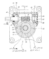
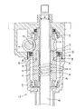
【図1】 本発明の実施の形態の第1例の全体構成を示す断面図。
【図2】 図1のA−A断面図。
【図3】 第1例の構造に組み込むボールナットとウォームホイールとを、一部を省略して示す分解斜視図。
【図4】 本発明の実施の形態の第2例の構造に組み込むボールナットとウォームホイールとを、組み立てた状態で示す半部断面図。
【図5】 従来構造の第1例を示す部分断面図。
【図6】 従来構造の第1例に組み込むボールナットとウォームホイールとを、一部を省略して示す分解斜視図。
【図7】 従来構造の第2例の構造に組み込むボールナットとウォームホイールとを、組み立てた状態で示す半部断面図。
【符号の説明】
1、1a ボールねじ式リニアアクチュエータ
2 減速機構
3、3a ボールナット
4 ボールねじ軸
5 ウォーム
6、6a ウォームホイール
7 第一螺旋溝
8 第二螺旋溝
9 ボール
10 内側円筒部
11 外側円筒部
12 第一平坦面
13 第二平坦面
14 突壁
15 第三平坦面
16、16a ケーシング
17 転がり軸受
18、19 キー溝
20 キー
21、21c ボールナット
22 平坦部
23 循環チューブ
24 段部
25 外輪
26 円輪板
27 覆いチューブ
28 雄ねじ
29 ねじ孔
30 ロックナット
31、31c ウォームホイール
32、32c 円筒部
33 ギヤ部
34、34b 鍔部
35、35c 切り欠き
36 凹溝
37、37c 突起
38 転がり軸受
39 入力軸
40 鍔部
41 外輪
42 固定蓋
43 ねじ蓋
45 小径部
47 小径部
48 大径部
49 内輪
[0001]
BACKGROUND OF THE INVENTION
The ball screw linear actuator according to the present invention can be used as a jack for lifting a heavy object, or as a power conversion device that is incorporated in various mechanical devices and obtains an output in a large linear motion direction from a small input torque.
[0002]
[Prior art]
As a ball screw type linear actuator that can be used as a jack or the like, those described in Japanese Utility Model Laid-Open No. 63-53058 are known. 5 to 6 show a main part of a ball screw type linear actuator that has been conventionally used, although it is slightly different from the structure described in this publication. This ball screw type linear actuator 1 rotates a ball nut 3 through a speed reduction mechanism 2 by an electric motor (not shown), and converts the rotation of the ball nut 3 into a linear motion of the ball screw shaft 4.
[0003]
The speed reduction mechanism 2 includes a worm 5 fixed to an input shaft that is rotationally driven by an electric motor (not shown) whose direction of rotation can be freely changed, and a worm wheel 6 that is a gear member meshed with the worm 5. Further, a first spiral groove 7 having an arc shape in cross section is formed on the outer peripheral surface of the ball screw shaft 4, and a second spiral groove 8 having an arc shape in cross section is formed on the inner peripheral surface of the ball nut 3, respectively. Forming. A plurality of balls 9, 9 are provided between the first spiral groove 7 and the second spiral groove 8 so as to roll freely, and the rotation of the ball nut 3 is converted into a linear motion of the ball screw shaft 4. For this purpose. When the ball screw linear actuator 1 is used, the end of the ball screw shaft 4 is coupled to the non-driving portion, so that the ball screw shaft 4 does not rotate.
[0004]
Further, the first flat surface 12 formed on a part of the outer peripheral surface of the ball nut 3 has an end portion of a pair of feed holes through which the balls 9 and 9 pass. Then, the end openings of these two feed holes are communicated with each other by a circulation tube, and the balls 9 and 9 moved to one end of the second spiral groove 8 are returned to the other end of the second spiral groove 8, A circulation mechanism for circulating the plurality of balls 9 is configured.
[0005]
The ball nut 3 and the worm wheel 6 are connected to each other in series and concentrically in the axial direction so that they cannot be rotated relative to each other. That is, the inner cylindrical portion 10 is formed at one end portion (right end portion in FIGS. 5 to 6 ) of the ball nut 3, and the outer cylindrical portion 11 is formed at one end portion (left end portion in FIGS. 5 to 6 ) of the worm wheel 6, respectively. The inner cylindrical portion 10 is fitted into the outer cylindrical portion 11 without rattling. A pair of second flat surfaces 13 and 13 parallel to each other are formed on the outer peripheral surface of the ball nut 3 at a portion closer to the center in the axial direction than the inner cylindrical portion 10. On the other hand, a pair of projecting walls 14 are formed on one end surface of the worm wheel 6 (the left end surface in FIGS. 5 to 6 ), and the inner peripheral side surfaces of both projecting walls 14 and 14 are parallel to each other. The third flat surfaces 15 and 15. The interval between the third flat surfaces 15 and 15 is the same as or slightly larger than the interval between the second flat surfaces 13 and 13. Accordingly, the second and third flat surfaces 13 and 15 are engaged with each other while the inner and outer cylindrical portions 10 and 11 are fitted to each other, and relative rotation between the ball nut 3 and the worm wheel 6 is performed. Make it impossible. The ball nut 3 and the worm wheel 6 combined as described above are rotatably supported by a pair of rolling bearings 17 and 17 inside the casing 16.
[0006]
When the ball screw linear actuator 1 configured as described above is used, the worm wheel 6 and the ball nut 3 are rotated in a desired direction via the worm 5 by rotating the electric motor. As a result, the ball screw shaft 4 screwed through the ball nut 3 and the plurality of balls 9 is displaced in the axial direction.
[0007]
In the case of the first example of the conventional structure described above, the ball nut 3 and the worm wheel 6 are connected in series in the axial direction. On the other hand, as shown in FIG. 7 , a structure in which a worm wheel 6a is fixed around a ball nut 3a has been conventionally known. In the case of the second example of this conventional structure, in order to prevent the worm wheel 6a from rotating with respect to the ball nut 3a, the key grooves 18, 19 are formed on the outer peripheral surface of the ball nut 3a and the inner peripheral surface of the worm wheel 6a. Is forming. And the key 20 is provided in the state over which these key grooves 18 and 19 are hung, and the said ball nut 3a and the worm wheel 6a can be rotated freely synchronizing.
[0008]
[Problems to be solved by the invention]
In the case of the first example of the conventional structure shown in FIGS. 5 to 6 , since the ball nut 3 and the worm wheel 6 are connected in series in the axial direction, the length in the axial direction may increase. Inevitable, the length dimension of the ball screw type linear actuator 1 becomes large. In the case of the second example of the conventional structure shown in FIG. 7 , since the key 20 is required to be provided inside the worm wheel 6a, the thickness dimensions of the ball nut 3a and the worm wheel 6a are increased, and the ball screw type Actuator diameter increases.
In view of such circumstances, the present invention has been invented to provide a small ball screw linear actuator with a reduced length and diameter.
[0009]
[Means for Solving the Problems]
As with the conventional ball screw linear actuator described above, the ball screw linear actuator of the present invention has a ball screw shaft in which a first spiral groove having a circular arc cross section is formed on the outer peripheral surface, and an inner peripheral surface. A ball nut formed with a second spiral groove having a circular arc cross section, a plurality of balls rotatably provided between the first spiral groove and the second spiral groove, and for circulating the plurality of balls. And a gear member having a gear fixed to the outer peripheral surface of the cylindrical portion (in the case of the invention described in claims 2 and 3) (intermediate portion) of the cylindrical portion, A reduction mechanism that includes a gear member and rotates the gear member in accordance with the rotation of the input shaft.
In particular, in the ball screw type linear actuator according to claim 1 of the present invention, the ball nut is recessed radially inward from the outer peripheral edge of the flange portion of the outward flange provided at the axial end portion of the ball nut. A pair of notches formed in a state, a pair of concave grooves formed over the entire length of the ball nut at a position matching the notches on the outer peripheral surface of the ball nut, and the gear member And a pair of protrusions that are formed in the same phase as the pair of notches, and project inward in the axial direction and radially inward of the gear member. Then, the gear member is externally fitted to the ball nut while the gear member is engaged with the ball nut and the inner diameter side ends of the protrusions and the concave grooves are engaged. By engaging the pair of protrusions and the pair of notches in a state where both side portions of the small-diameter portion and the inner peripheral surface of the gear member are fitted with an interference fit, the gear member is engaged with the ball. It can be rotated in synchronization with the nut.
Further, in the ball screw type linear actuator described in claim 2, in addition to the structure described in claim 1, the gear is fixed to an intermediate portion of the outer peripheral surface of the gear member. In addition, a small-diameter portion is formed in a portion existing on the inner side in the diameter direction of the gear in a state combined with the gear member on the outer peripheral surface of the intermediate portion of the ball nut. And the outer peripheral surface of the said ball nut and the inner peripheral surface of the said gear member are fitted by the interference fit in the both-sides part of the said small diameter part .
Furthermore, in the ball screw type linear actuator according to claim 3, the ball screw type linear actuator is formed so as to be recessed radially inward from the outer peripheral edge of the flange portion of the outward flange provided at one axial end portion of the ball nut. A pair of notches and one end portion in the axial direction of the gear member formed in the same phase as the pair of notches, each projecting in the axial direction of the gear member, and each inner peripheral side surface of the gear member A pair of protrusions present radially outward from the inner peripheral surface of the ball, a large-diameter portion formed on the outer peripheral surface of one axial end portion of the ball nut and having an axial dimension larger than the flange, A small-diameter portion formed on the inner peripheral surface of the other axial end portion of the gear member. Then, one end of the axial end portions of the gear member is fitted to the large diameter portion, and the small diameter portion of the other axial end portion is externally fitted to the other axial end portion of the ball nut by an interference fit. By engaging the pair of protrusions with the pair of notches, the gear member can be rotated in synchronization with the ball nut, and one end of the gear member in the axial direction and the large diameter And the axial length of the fitting portion between the small-diameter portion of the other axial end portion of the gear member and the other axial end portion of the ball nut. It is smaller than the axial length of the protrusion.
[0010]
[Action]
According to the ball screw linear actuator of the present invention configured as described above, the length and diameter of the combined portion of the ball nut and the gear member can be reduced, and a small and lightweight ball screw linear actuator is realized. it can. In addition, according to the present invention, the structure in which the ball nut and the gear member can be prevented from being displaced in the axial direction, and the operation of engaging each protrusion and each notch can be easily performed. Furthermore, according to the invention described in claims 2 and 3 of the present invention, the gear portion provided on the outer peripheral surface of the gear member may be deformed in accordance with the combination of the ball nut and the gear member. Can be prevented.
[0011]
DETAILED DESCRIPTION OF THE INVENTION
1-3 show a first example of an embodiment of the present invention corresponding to claims 1 and 2. Both ends of the ball nut 21 are rotatably supported by a pair of rolling bearings 17 and 17 inside the casing 16a. That is, small diameter step portions 24, 24 are formed at both ends of the ball nut 21, and the rolling bearings 17, 17 are provided between both the step portions 24, 24 and the inner peripheral surface of the casing 16a. . Among these rolling bearings 17 and 17, an outer end surface (right end surface in FIG. 1) of the outer ring 25 constituting one (right side in FIG. 1) abuts against a part of the inner surface of the casing 16a. The outer end surface (left end surface in FIG. 1) of the outer ring 25 constituting the other (left side in FIG. 1) is one side surface (right side surface in FIG. 1) of the annular plate 26 provided in the casing 16a. It hits the part near the outer periphery.
[0012]
Furthermore, the base end edge (right end edge in FIG. 1) of the cover tube 27 is abutted against the inner peripheral portion of the other side surface (left side face in FIG. 1) of the annular plate 26. The cover tube 27 is fixed to the casing 16a by screwing a male screw 28 formed on the outer peripheral surface of the base end portion thereof into a screw hole 29 formed in the casing 16a and further tightening a lock nut 30. . In this state, the base end edge of the cover tube 27 presses the annular plate 26 toward the outer end surface of the outer ring 25 constituting the other rolling bearing 17 in a state of being fixed to the casing 16a. A desired preload is applied to the bearings 17 and 17. In the illustrated example, tapered roller bearings capable of supporting large radial loads and thrust loads are used as the rolling bearings 17 and 17.
[0013]
A ball screw shaft 4 is inserted inside the ball nut 21, and a part of the ball screw shaft 4 is inserted into the cover tube 27. And between the 1st spiral groove 7 of the cross-section arc shape formed in the outer peripheral surface of this ball screw shaft 4, and the 2nd spiral groove 8 of the cross-section arc shape formed in the inner peripheral surface of the said ball nut 21. A plurality of balls 9 are provided so as to be freely rotatable, and the ball screw shaft 4 is displaceable in the axial direction based on the rotation of the ball nut 21. A first flat surface 12 is formed on a part of the outer peripheral surface of the ball nut 21, and a pair of feed holes for allowing the balls 9, 9 to pass through the first flat surface 12 respectively. The end of is opened. The end openings of these feed holes are communicated with each other by the circulation tube 23. The pair of feed holes and the circulation tube 23 return the balls 9, 9 moved to one end of the second spiral groove 8 to the other end of the second spiral groove 8, and the plurality of balls 9, 9 constitutes a circulation mechanism.
[0014]
A worm wheel 31 as a gear member is rotatably provided around the ball nut 21 together with the ball nut 21. The worm wheel 31 includes a cylindrical portion 32 that can be fitted to the ball nut 21 without looseness, and a gear portion 33 that is integrally provided on the outer peripheral surface of the intermediate portion of the cylindrical portion 32. In order to allow the ball nut 21 and the worm wheel 31 to rotate in synchronization, an outward flange-like flange portion 34 is formed on the outer peripheral surface of one end portion (the left end portion in FIGS. 1 and 3) of the ball nut 21. At the same time, a pair of notches 35 are formed at two positions on the opposite side in the diameter direction of the flange 34. Further, at two positions opposite to the diameter direction of the outer peripheral surface of the ball nut 21, the grooves 36 and 36 are respectively formed at the positions aligned with the pair of notches 35 and 35 so as to extend to the entire length of the ball nut 21. It is formed in a row. The concave grooves 36 and 36 and the widths of the notches 35 and 35 are made to coincide with each other. Accordingly, one end portion (the left end portion in FIGS. 1 and 3) of each of the concave grooves 36 and 36 coincides with the deep end portion of each of the notches 35 and 35.
[0015]
On the other hand, a pair of protrusions 37, 37 are provided in the axial direction from one end surface in the axial direction at two positions opposite to each other in the diameter direction of the one end surface in the axial direction of the worm wheel 31 (the left end surface in FIGS. 1 and 3). It is formed in a protruding state. Further, the inner diameter side surface of each of the projections 37, 37 slightly protrudes inward in the diameter direction from the inner peripheral surface of the worm wheel 31. The width W 37 of each of the protrusions 37 and 37 is slightly smaller than the width W 36 of each of the concave grooves 36 and 36 and the notches 35 and 35 (W 37 <W 36 ). 37 engages with the concave grooves 36 and 36 and the notches 35 and 35 without rattling.
[0016]
In order to constitute the ball screw type linear actuator 1a, the pair of protrusions 37, 37 and the pair of notches 35, with the cylindrical portion 32 constituting the worm wheel 31 fitted on the ball nut 21, 35 engages. The worm wheel 31 and the ball nut 21 are rotatable in synchronization. In the case of this example to combine the worm wheel 31 and the ball nut 21, first, the inner diameter side end of each of the projections 37, 37 is connected to the other end of each of the concave grooves 36, 36 (see FIGS. 1 and 3). (Right end) Engage from the opening. If the worm wheel 31 is fitted on the ball nut 21 while sliding the projections 37 and 37 along the concave grooves 36 and 36, the projections 37 and 37 and the notches 35 and 35 can be easily engaged with each other.
[0017]
The worm wheel 31 is press-fitted to the ball nut 21 with a predetermined tightening allowance, and the worm wheel 31 is applied regardless of the thrust load applied to the worm wheel 31 based on the engagement between the gear portion 33 and the worm 5. Prevents the ball nut 21 from shifting in the axial direction. However, a small-diameter portion 45 is formed in the outer peripheral surface of the intermediate portion of the ball nut 21 on the inner side in the diameter direction of the gear portion 33 to prevent the gear portion 33 from being deformed due to press-fitting. is doing.
[0018]
The speed reduction mechanism 2 is configured by engaging the worm 5 with the gear portion 33 of the worm wheel 31 that is externally fitted and fixed to the ball nut 21 as described above. An input shaft 39 provided with the worm 5 at its intermediate portion is arranged in a torsional positional relationship with respect to the central axis of the worm wheel 31, and a pair of rolling bearings 38, 38 are provided inside the casing 16a. It is supported rotatably. In the illustrated example, an angular ball bearing is used as each of the rolling bearings 38, 38. Then, the opposite end surfaces of the inner rings 49, 49 constituting the both rolling bearings 38, 38 are abutted against flanges 40, 40 formed on the end portion of the input shaft 39 or the outer peripheral surface of the intermediate portion. Further, the opposite end surfaces of the outer rings 41, 41 constituting the both rolling bearings 38, 38 protrude into a part of a fixed lid 42 fixed to the casing 16a or a screw lid 43 screwed to the casing 16a. I guess. The screw lid 43 presses the pair of outer rings 41, 41 in a direction approaching each other with the fixed lid 42, thereby applying a predetermined preload to the pair of rolling bearings 38, 38. .
[0019]
When the ball screw linear actuator 1a of the present invention configured as described above is used, the worm wheel 31 is moved via the worm 5 by manually rotating an electric motor (not shown) or a handle (not shown). Rotate in desired direction. The rotation of the worm wheel 31 is transmitted to the ball nut 21 by the engaging portion between the pair of projections 37, 37 and the notches 35, 35, and the ball nut 21 rotates in the desired direction. As a result, the ball screw shaft 4 screwed through the ball nut 21 and the plurality of balls 9 is displaced in the axial direction. In particular, in the case of the ball screw type linear actuator 1a of this example , the engaging portions between the pair of protrusions 37, 37 and the notches 35, 35 are at the end portions of the worm wheel 31 and the ball nut 21. Since it exists, the length and diameter of the part which combined these both members 31 and 21 can be made small. And the small and lightweight ball screw type linear actuator 1a is realizable.
[0020]
Next, FIG. 4 shows a second example of an embodiment of the present invention corresponding to claim 3 . In the case of this example, the inner peripheral side surface of the projection 37c formed at two positions opposite to the diametrical direction of the one end edge (left end edge in FIG. 4 ) of the cylindrical portion 32c constituting the worm wheel 31c is connected to the cylindrical portion 32c . It is located on the outer side in the diameter direction than the inner peripheral surface. A small-diameter portion 47 is formed on the inner peripheral surface of the other end portion (the right end portion in FIG. 4 ) of the worm wheel 31c. On the other hand, a large diameter portion 48 is formed on the outer peripheral surface of one end portion (left end portion in FIG. 4 ) of the ball nut 21c. Further, a flange 34b is formed at one end edge of the ball nut 21c located on the outer half side of the large-diameter portion 48, and notches 35c are respectively provided at two positions on the opposite side in the diameter direction of the flange 34b. Forming. The notches 35c and the protrusions 37c are engaged with each other.
[0021]
In the case of this example, the worm wheel 31c is displaced in the axial direction with respect to the ball nut 21c. The outer peripheral surface of the small-diameter portion 47 and the outer periphery of the other end portion (right end portion in FIG. 4 ) of the ball nut 21c . This is prevented based on the fitting by the interference fitting with the surface and the fitting by the interference fitting between the outer peripheral surface of the large diameter portion 48 and the inner peripheral surface of the one end portion of the worm wheel 31c. The length L 37c of each projection 37c has a width W 47 of the fitting portion of the other end portion of the small-diameter portion 47 and the ball nut 21c, as well as among the large diameter portion 48 from the inner surface of the flange section 34b It is larger than the distance L 48 to the edge (L 37c > W 47 , L 37c > L 48 ).
[0022]
Accordingly, when the worm wheel 31c is externally fitted to the ball nut 21c, one end of the worm wheel 31c is externally connected to the large diameter portion 48, and the small diameter portion 47 is externally connected to the other end of the ball nut 21c. Prior to fitting, the tip of each projection 37c is inserted into each notch 35c. For this reason, the operation of engaging the projections 37c and 37c with the notches 35c and 35c can be easily performed without providing a guide groove or the like. The worm wheel 31c and the ball nut 21c configured and combined as described above constitute a ball screw type linear actuator in combination with other components as in the structure of the first example described above.
[0023]
【The invention's effect】
Since the present invention is configured and operates as described above, it can contribute to the realization of a small and lightweight ball screw linear actuator.
[Brief description of the drawings]
FIG. 1 is a cross-sectional view showing an overall configuration of a first example of an embodiment of the present invention.
FIG. 2 is a cross-sectional view taken along the line AA in FIG.
FIG. 3 is an exploded perspective view showing the ball nut and the worm wheel incorporated in the structure of the first example with a part thereof omitted.
FIG. 4 is a half sectional view showing a ball nut and a worm wheel incorporated in the structure of the second example of the embodiment of the present invention in an assembled state.
FIG. 5 is a partial sectional view showing a first example of a conventional structure.
FIG. 6 is an exploded perspective view showing the ball nut and the worm wheel incorporated in the first example of the conventional structure with a part thereof omitted.
FIG. 7 is a half sectional view showing a ball nut and a worm wheel incorporated in the structure of the second example of the conventional structure in an assembled state.
[Explanation of symbols]
DESCRIPTION OF SYMBOLS 1, 1a Ball screw type linear actuator 2 Deceleration mechanism 3, 3a Ball nut 4 Ball screw shaft 5 Worm 6, 6a Worm wheel 7 First spiral groove 8 Second spiral groove 9 Ball 10 Inner cylindrical part 11 Outer cylindrical part 12 First Flat surface 13 Second flat surface 14 Projecting wall 15 Third flat surface 16, 16a Casing 17 Rolling bearing 18, 19 Key groove 20 Key 21 , 21c Ball nut 22 Flat portion 23 Circulating tube 24 Step portion 25 Outer ring 26 Ring plate 27 Cover tube 28 Male screw 29 Screw hole 30 Lock nut 31 , 31 c Worm wheel 32 , 32 c Cylindrical portion 33 Gear portion 34 , 34 bportion 35 , 35 c Notch 36 Concave groove 37 , 37 c Protrusion 38 Rolling bearing 39 Input shaft 40 鍔 portion 41 Outer ring 42 Fixed lid 43 Screw lid
45 small diameter part
47 Small diameter part 48 Large diameter part 49 Inner ring

Claims (3)

外周面に断面円弧形の第一螺旋溝を形成したボールねじ軸と、内周面に断面円弧形の第二螺旋溝を形成したボールナットと、上記第一螺旋溝と上記第二螺旋溝との間に転動自在に設けた複数のボールと、これら複数のボールを循環させる為の循環機構と、上記ボールナットに外嵌する円筒部及びこの円筒部の外周面に固設したギヤを有するギヤ部材と、このギヤ部材を含んで構成され、入力軸の回転に伴って上記ギヤ部材を回転させる減速機構とを備えたボールねじ式リニアアクチュエータに於いて、上記ボールナットの軸方向端部に設けた外向フランジ状の鍔部の外周縁から径方向内方に凹む状態で形成した1対の切り欠きと、上記ボールナットの外周面のうちでこれら両切り欠きに整合する位置にこのボールナットの全長に亙って形成された1対の凹溝と、上記ギヤ部材の軸方向端部に、上記1対の切り欠きと同じ位相で形成した、それぞれがこのギヤ部材の軸方向及び径方向内方に突出する1対の突起とを備え、上記ギヤ部材を上記ボールナットに、上記両突起の内径側端部と上記両凹溝とを係合させつつこのギヤ部材をこのボールナットに外嵌し、このボールナットの外周面とこのギヤ部材の内周面とを締り嵌めで嵌合させた状態で上記1対の突起と上記1対の切り欠きとを係合させる事により、上記ギヤ部材を上記ボールナットと同期して回転自在とした事を特徴とするボールねじ式リニアアクチュエータ。  A ball screw shaft having a first spiral groove having an arc-shaped cross section on the outer peripheral surface, a ball nut having a second spiral groove having an arc-shaped cross section on the inner peripheral surface, the first spiral groove and the second spiral A plurality of balls that can be freely rolled between the grooves, a circulation mechanism for circulating the plurality of balls, a cylindrical portion that is externally fitted to the ball nut, and a gear that is fixed to the outer peripheral surface of the cylindrical portion A ball screw type linear actuator comprising a gear member having a gear member and a speed reduction mechanism configured to rotate the gear member as the input shaft rotates. This pair of notches formed in a state of being recessed radially inward from the outer peripheral edge of the flange portion of the outward flange shape provided in the portion, and this ball at a position aligned with both of the notches on the outer peripheral surface of the ball nut Formed over the entire length of the nut A pair of concave grooves and an axial end of the gear member formed in the same phase as the pair of notches, each projecting in the axial direction and the radially inward direction of the gear member. A projection, and the gear member is externally fitted to the ball nut while the gear member is engaged with the ball nut, the inner diameter side ends of the projections and the concave grooves are engaged, and the outer circumference of the ball nut is The gear member is synchronized with the ball nut by engaging the pair of protrusions and the pair of notches in a state where the surface and the inner peripheral surface of the gear member are fitted with an interference fit. Ball screw type linear actuator characterized by being freely rotatable. ギヤをギヤ部材の外周面の中間部に固設しており、ボールナットの中間部外周面でこのギヤ部材と組み合わせた状態で上記ギヤの直径方向内側に存在する部分に小径部を形成しており、上記ボールナットの外周面と上記ギヤ部材の内周面とを、上記小径部の両側部分で締り嵌めで嵌合させている、請求項1に記載したボールねじ式リニアアクチュエータ。  A gear is fixed to an intermediate portion of the outer peripheral surface of the gear member, and a small-diameter portion is formed in a portion existing on the inner side in the diameter direction of the gear in a state combined with this gear member on the outer peripheral surface of the intermediate portion of the ball nut. The ball screw linear actuator according to claim 1, wherein the outer peripheral surface of the ball nut and the inner peripheral surface of the gear member are fitted by interference fit at both side portions of the small diameter portion. 外周面に断面円弧形の第一螺旋溝を形成したボールねじ軸と、内周面に断面円弧形の第二螺旋溝を形成したボールナットと、上記第一螺旋溝と上記第二螺旋溝との間に転動自在に設けた複数のボールと、これら複数のボールを循環させる為の循環機構と、上記ボールナットに外嵌する円筒部及びこの円筒部の中間部外周面に固設したギヤを有するギヤ部材と、このギヤ部材を含んで構成され、入力軸の回転に伴って上記ギヤ部材を回転させる減速機構とを備えたボールねじ式リニアアクチュエータに於いて、上記ボールナットの軸方向一端部に設けた外向フランジ状の鍔部の外周縁から径方向内方に凹む状態で形成した1対の切り欠きと、上記ギヤ部材の軸方向一端部に、これら1対の切り欠きと同じ位相で形成した、それぞれがこのギヤ部材の軸方向に突出する、それぞれの内周側面がこのギヤ部材の内周面よりも径方向外方に存在する1対の突起と、上記ボールナットの軸方向一端部外周面に形成した、上記鍔部よりも大きな軸方向寸法を有する大径部と、上記ギヤ部材の軸方向他端部内周面に形成した小径部とを備え、このギヤ部材の軸方向両端部のうちの一端部を上記大径部に、軸方向他端部の小径部を上記ボールナットの軸方向他端部に、それぞれ締り嵌めで外嵌した状態で上記1対の突起と上記1対の切り欠きとを係合させる事により、上記ギヤ部材を上記ボールナットと同期して回転自在とすると共に、上記ギヤ部材の軸方向一端部と上記大径部との嵌合部の軸方向長さ、及び、このギヤ部材の軸方向他端部の小径部と上記ボールナットの軸方向他端部との嵌合部の軸方向長さを、上記両突起の軸方向長さよりも小さくした事を特徴とするボールねじ式リニアアクチュエータ。  A ball screw shaft having a first spiral groove having an arc-shaped cross section on the outer peripheral surface, a ball nut having a second spiral groove having an arc-shaped cross section on the inner peripheral surface, the first spiral groove and the second spiral A plurality of balls provided between the grooves so as to be freely rotatable, a circulation mechanism for circulating the plurality of balls, a cylindrical portion that is externally fitted to the ball nut, and an outer peripheral surface of an intermediate portion of the cylindrical portion. A ball screw type linear actuator comprising a gear member having a gear and a speed reduction mechanism that includes the gear member and rotates the gear member as the input shaft rotates. A pair of notches formed in a radially indented state from the outer peripheral edge of the flange portion of the outward flange shape provided at one end in the direction, and the pair of notches at one end in the axial direction of the gear member Each gear is formed with the same phase Each of the inner peripheral side surfaces protruding in the axial direction of the gear member is formed on a pair of protrusions present radially outward from the inner peripheral surface of the gear member, and an outer peripheral surface of one end of the ball nut in the axial direction. A large-diameter portion having an axial dimension larger than the flange portion, and a small-diameter portion formed on the inner peripheral surface of the other axial end portion of the gear member, and one end portion of the axial end portions of the gear member is Engage the pair of protrusions and the pair of notches with the large-diameter portion and the small-diameter portion at the other axial end on the other axial end of the ball nut. The gear member can be rotated in synchronization with the ball nut, and the axial length of the fitting portion between the one axial end portion of the gear member and the large diameter portion, and the gear member Of the fitting portion between the small diameter portion of the other axial end of the ball nut and the other axial end of the ball nut. The direction length, ball screw type linear actuator, characterized in that is smaller than the axial length of the both projections.
JP26320296A 1996-10-03 1996-10-03 Ball screw type linear actuator Expired - Fee Related JP3944927B2 (en)

Priority Applications (1)

Application Number Priority Date Filing Date Title
JP26320296A JP3944927B2 (en) 1996-10-03 1996-10-03 Ball screw type linear actuator

Applications Claiming Priority (1)

Application Number Priority Date Filing Date Title
JP26320296A JP3944927B2 (en) 1996-10-03 1996-10-03 Ball screw type linear actuator

Publications (2)

Publication Number Publication Date
JPH10110800A JPH10110800A (en) 1998-04-28
JP3944927B2 true JP3944927B2 (en) 2007-07-18

Family

ID=17386205

Family Applications (1)

Application Number Title Priority Date Filing Date
JP26320296A Expired - Fee Related JP3944927B2 (en) 1996-10-03 1996-10-03 Ball screw type linear actuator

Country Status (1)

Country Link
JP (1) JP3944927B2 (en)

Families Citing this family (9)

* Cited by examiner, † Cited by third party
Publication number Priority date Publication date Assignee Title
JP2003053246A (en) * 2001-08-20 2003-02-25 Hirano Tecseed Co Ltd Bending correction device for roll
JP4295575B2 (en) 2003-08-05 2009-07-15 株式会社リコー Image carrier driving apparatus, image forming apparatus, and process cartridge
JP2007196751A (en) 2006-01-24 2007-08-09 Jtekt Corp Electric power steering device
JP4811821B2 (en) * 2007-10-23 2011-11-09 本田技研工業株式会社 Linear actuator
CN104709842A (en) * 2015-01-29 2015-06-17 张宏松 Heavy type jack
JP6370746B2 (en) * 2015-07-01 2018-08-08 株式会社椿本チエイン Linear actuator
CN106641156A (en) * 2016-08-30 2017-05-10 无锡艾尔特线性运动机械有限公司 Opening type electric push rod
DE202019103358U1 (en) * 2019-06-14 2020-09-15 Dewertokin Gmbh linear actuator
WO2021210307A1 (en) * 2020-04-13 2021-10-21 日本精工株式会社 Ball screw device

Also Published As

Publication number Publication date
JPH10110800A (en) 1998-04-28

Similar Documents

Publication Publication Date Title
EP0548888B1 (en) Internally meshing planetary gear structure
EP0556587B1 (en) Series of speed increasing and reduction gear employing an inscribed meshing type planetary gear construction
EP0291052A2 (en) Planetary gear system
US8151959B2 (en) One-way clutch unit
JP2000145914A (en) Bearing linear actuator with backstop mechanism
JP3944927B2 (en) Ball screw type linear actuator
US9145919B2 (en) Speed-reduction transmission bearing
JP2002021948A (en) Unit type wave gear device
KR20160136814A (en) Reverse cycloid reducer
WO2020218505A1 (en) Speed reducer and driving device
JP3807043B2 (en) Ball screw type linear actuator
JP2003235206A (en) Motor
JPH086785B2 (en) Planetary gear
EP2730805B1 (en) Reduction gear
JP3941512B2 (en) Linear actuator with clutch mechanism
GB2587799A (en) A Gearbox assembly and worm shaft assembly therefore
JP2003319607A (en) Linear actuator
KR200333593Y1 (en) A planetary gear drive with carrier
JP4672983B2 (en) Reducer output section structure
JP4239515B2 (en) Ball screw device
JPH09144852A (en) Differential device
KR101895449B1 (en) Crank assembly for increasing a rotational force
JPH05215191A (en) Planetary gear device without backlash
JP2010007850A (en) Ball screw device with support bearing
JPH0319116B2 (en)

Legal Events

Date Code Title Description
A977 Report on retrieval

Free format text: JAPANESE INTERMEDIATE CODE: A971007

Effective date: 20060223

A131 Notification of reasons for refusal

Free format text: JAPANESE INTERMEDIATE CODE: A131

Effective date: 20060516

A521 Written amendment

Free format text: JAPANESE INTERMEDIATE CODE: A523

Effective date: 20060714

A131 Notification of reasons for refusal

Free format text: JAPANESE INTERMEDIATE CODE: A131

Effective date: 20070116

A521 Written amendment

Free format text: JAPANESE INTERMEDIATE CODE: A523

Effective date: 20070302

TRDD Decision of grant or rejection written
A01 Written decision to grant a patent or to grant a registration (utility model)

Free format text: JAPANESE INTERMEDIATE CODE: A01

Effective date: 20070320

A61 First payment of annual fees (during grant procedure)

Free format text: JAPANESE INTERMEDIATE CODE: A61

Effective date: 20070402

R150 Certificate of patent or registration of utility model

Free format text: JAPANESE INTERMEDIATE CODE: R150

FPAY Renewal fee payment (event date is renewal date of database)

Free format text: PAYMENT UNTIL: 20100420

Year of fee payment: 3

FPAY Renewal fee payment (event date is renewal date of database)

Free format text: PAYMENT UNTIL: 20110420

Year of fee payment: 4

FPAY Renewal fee payment (event date is renewal date of database)

Free format text: PAYMENT UNTIL: 20120420

Year of fee payment: 5

FPAY Renewal fee payment (event date is renewal date of database)

Free format text: PAYMENT UNTIL: 20130420

Year of fee payment: 6

FPAY Renewal fee payment (event date is renewal date of database)

Free format text: PAYMENT UNTIL: 20130420

Year of fee payment: 6

FPAY Renewal fee payment (event date is renewal date of database)

Free format text: PAYMENT UNTIL: 20140420

Year of fee payment: 7

LAPS Cancellation because of no payment of annual fees