JP3944165B2 - Switchable electrochromic device - Google Patents
Switchable electrochromic device Download PDFInfo
- Publication number
- JP3944165B2 JP3944165B2 JP2003517667A JP2003517667A JP3944165B2 JP 3944165 B2 JP3944165 B2 JP 3944165B2 JP 2003517667 A JP2003517667 A JP 2003517667A JP 2003517667 A JP2003517667 A JP 2003517667A JP 3944165 B2 JP3944165 B2 JP 3944165B2
- Authority
- JP
- Japan
- Prior art keywords
- window assembly
- conductive coating
- spacing
- electrochromic
- assembly
- Prior art date
- Legal status (The legal status is an assumption and is not a legal conclusion. Google has not performed a legal analysis and makes no representation as to the accuracy of the status listed.)
- Expired - Fee Related
Links
Images


Classifications
-
- B—PERFORMING OPERATIONS; TRANSPORTING
- B64—AIRCRAFT; AVIATION; COSMONAUTICS
- B64C—AEROPLANES; HELICOPTERS
- B64C1/00—Fuselages; Constructional features common to fuselages, wings, stabilising surfaces or the like
- B64C1/14—Windows; Doors; Hatch covers or access panels; Surrounding frame structures; Canopies; Windscreens accessories therefor, e.g. pressure sensors, water deflectors, hinges, seals, handles, latches, windscreen wipers
- B64C1/1476—Canopies; Windscreens or similar transparent elements
- B64C1/1492—Structure and mounting of the transparent elements in the window or windscreen
-
- B—PERFORMING OPERATIONS; TRANSPORTING
- B64—AIRCRAFT; AVIATION; COSMONAUTICS
- B64C—AEROPLANES; HELICOPTERS
- B64C1/00—Fuselages; Constructional features common to fuselages, wings, stabilising surfaces or the like
- B64C1/14—Windows; Doors; Hatch covers or access panels; Surrounding frame structures; Canopies; Windscreens accessories therefor, e.g. pressure sensors, water deflectors, hinges, seals, handles, latches, windscreen wipers
- B64C1/1476—Canopies; Windscreens or similar transparent elements
- B64C1/1484—Windows
-
- G—PHYSICS
- G02—OPTICS
- G02F—OPTICAL DEVICES OR ARRANGEMENTS FOR THE CONTROL OF LIGHT BY MODIFICATION OF THE OPTICAL PROPERTIES OF THE MEDIA OF THE ELEMENTS INVOLVED THEREIN; NON-LINEAR OPTICS; FREQUENCY-CHANGING OF LIGHT; OPTICAL LOGIC ELEMENTS; OPTICAL ANALOGUE/DIGITAL CONVERTERS
- G02F1/00—Devices or arrangements for the control of the intensity, colour, phase, polarisation or direction of light arriving from an independent light source, e.g. switching, gating or modulating; Non-linear optics
- G02F1/01—Devices or arrangements for the control of the intensity, colour, phase, polarisation or direction of light arriving from an independent light source, e.g. switching, gating or modulating; Non-linear optics for the control of the intensity, phase, polarisation or colour
- G02F1/15—Devices or arrangements for the control of the intensity, colour, phase, polarisation or direction of light arriving from an independent light source, e.g. switching, gating or modulating; Non-linear optics for the control of the intensity, phase, polarisation or colour based on an electrochromic effect
- G02F1/153—Constructional details
- G02F1/155—Electrodes
-
- G—PHYSICS
- G02—OPTICS
- G02F—OPTICAL DEVICES OR ARRANGEMENTS FOR THE CONTROL OF LIGHT BY MODIFICATION OF THE OPTICAL PROPERTIES OF THE MEDIA OF THE ELEMENTS INVOLVED THEREIN; NON-LINEAR OPTICS; FREQUENCY-CHANGING OF LIGHT; OPTICAL LOGIC ELEMENTS; OPTICAL ANALOGUE/DIGITAL CONVERTERS
- G02F1/00—Devices or arrangements for the control of the intensity, colour, phase, polarisation or direction of light arriving from an independent light source, e.g. switching, gating or modulating; Non-linear optics
- G02F1/01—Devices or arrangements for the control of the intensity, colour, phase, polarisation or direction of light arriving from an independent light source, e.g. switching, gating or modulating; Non-linear optics for the control of the intensity, phase, polarisation or colour
- G02F1/15—Devices or arrangements for the control of the intensity, colour, phase, polarisation or direction of light arriving from an independent light source, e.g. switching, gating or modulating; Non-linear optics for the control of the intensity, phase, polarisation or colour based on an electrochromic effect
- G02F1/163—Operation of electrochromic cells, e.g. electrodeposition cells; Circuit arrangements therefor
Description
本発明は、切替可能エレクトロクロミック装置に関し、これらは、その全構造全体にわたって均一に切り替えることができ、また、選択領域に対して優先的に切り替えることができる。さらに特定すると、本発明は、切替可能エレクトロクロミック装置(特に、大規模透明窓または不均一形状透明窓)に関し、これらは、起動状態から停止状態へと均一に切り替えることができ、また、起動領域および停止領域の両方を同時に含み得る。 The present invention relates to a switchable electrochromic device, which can be switched uniformly across its entire structure and can be preferentially switched over a selected region. More particularly, the present invention relates to a switchable electrochromic device (especially a large transparent window or a non-uniformly shaped transparent window), which can be switched uniformly from an activated state to a deactivated state, And both stop regions can be included simultaneously.
市販のエレクトロクロミック装置は、自動車のミラーとして使用することが当該技術分野で周知である。特許文献には、また、自動車の窓、航空機の窓アセンブリ、サンルーフ、天窓および建築用の窓に平坦型のエレクトロクロミック装置を使用することが論述されている。このようなエレクトロクロミック装置は、典型的には、密封チャンバを含み、これは、2枚のガラスにより規定され、これらのガラスは、エレクトロクロミック媒体を含む間隙または空間により、分離されている。このエレクトロクロミック媒体は、典型的には、溶液中にて、アノード性化合物およびカソード性化合物を共に含有する。それらのガラス基板は、典型的には、透明導電層を含み、これらは、そのガラスの対向面で被覆されており、このエレクトロクロミック媒体に接触している。両方のガラス基板上の導電層は、電気回路に接続される。これらの導電層が電気エネルギーを加えられるとき、加えた電位は、その装置のチャンバに導入され、これは、このエレクトロクロミック媒体に電気エネルギーを加えて、その媒体の色を変える。例えば、このエレクトロクロミック媒体は、エネルギーが加えられると、暗くなり得、光を吸収し始める。自動車用のエレクトロクロミックバックミラーアセンブリには、このミラーで反射された光の変化を検出するために、また、電位を起動してそのミラーを薄暗くするために、光電セルを組み込むことができる。 Commercially available electrochromic devices are well known in the art for use as automotive mirrors. The patent literature also discusses the use of flat electrochromic devices in automotive windows, aircraft window assemblies, sunroofs, skylights and architectural windows. Such electrochromic devices typically include a sealed chamber, which is defined by two glasses, which are separated by a gap or space that contains an electrochromic medium. The electrochromic medium typically contains both an anodic compound and a cathodic compound in solution. The glass substrates typically include a transparent conductive layer, which is coated with the opposing surface of the glass and is in contact with the electrochromic medium. The conductive layers on both glass substrates are connected to the electrical circuit. When these conductive layers are energized, the applied potential is introduced into the chamber of the device, which applies electrical energy to the electrochromic medium and changes the color of the medium. For example, the electrochromic medium can become dark when energy is applied and begins to absorb light. An electrochromic rearview mirror assembly for an automobile can incorporate a photocell to detect changes in the light reflected by the mirror and to activate a potential to dim the mirror.
エレクトロクロミック装置の他の提案された用途では、そのエレクトロクロミック装置のサイズが大きくなるにつれて、種々の問題が一般的となっている。例えば、バックミラーアセンブリは、小型エレクトロクロミックアセンブリを含み、これは、典型的には、約2インチ×10インチ(5.08cm〜25.4cm)の大きさである。このようなエレクトロクロミック装置では、アノード性バスバーは、典型的には、そのミラーアセンブリの上部にあり、また、カソード性バスバーは、典型的には、このミラーアセンブリの下部に配列される。 In other proposed applications of electrochromic devices, various problems become common as the size of the electrochromic device increases. For example, the rearview mirror assembly includes a miniature electrochromic assembly, which is typically about 2 inches by 10 inches (5.08 cm to 25.4 cm) in size. In such electrochromic devices, the anodic bus bar is typically at the top of the mirror assembly and the cathodic bus bar is typically arranged at the bottom of the mirror assembly.
他方、自動車の窓、建築用の窓、および一部の航空機の窓は、規模がずっと大きい。結果として、エレクトロクロミックバックミラーアセンブリでの明るい状態と暗い状態との間の切替は、典型的には、迅速かつ一様であるのに対して、大規模エレクトロクロミック装置での明るい状態と暗い状態との間の切替は、遅くかつ不均一であり得る。徐々に起こる不均一な着色または切替は、大規模エレクトロクロミック窓アセンブリに付随した一般的な問題であり、これは、通例、「虹彩効果」と呼ばれている。この効果は、典型的には、これらの基板の表面に存在している透明導電性被覆の表面を横切る電位の低下が原因であり、その結果、加えた電位は、その表面被覆の縁部に沿って、このバスバーに隣接して、最も高くなり、また、その電流がエレクトロクロミック溶液を通るとき、そのセルの中心で、最も低くなる。従って、このエレクトロクロミック媒体は、典型的には、これらのバスバーが位置しているセルの周辺(すなわち、加えた電位がエレクトロクロミック媒体と接触する地点に最も近い地点)を最初に着色することにより、その後、このセルの中心に向かって着色することにより、不均一な着色を示す。伝統的には、シート抵抗が高い導電性フィルムが使用される。しかしながら、このような高いシート抵抗を切り替えるには、高い電圧および長時間を要する。さらに、通常のエレクトロクロミック装置では、その全アセンブリは、電位を加えると、陰になる。 On the other hand, automobile windows, architectural windows, and some aircraft windows are much larger. As a result, switching between bright and dark states in electrochromic rearview mirror assemblies is typically fast and uniform, whereas bright and dark states in large electrochromic devices Switching between and can be slow and non-uniform. Gradual non-uniform coloration or switching is a common problem associated with large electrochromic window assemblies, commonly referred to as the “iris effect”. This effect is typically due to a decrease in potential across the surface of the transparent conductive coating present on the surface of these substrates, so that the applied potential is applied to the edge of the surface coating. Along the bus bar, the highest, and the lowest at the center of the cell when the current passes through the electrochromic solution. Thus, this electrochromic medium is typically colored by first coloring the periphery of the cell where these busbars are located (ie, the point closest to the point where the applied potential contacts the electrochromic medium). Thereafter, coloring toward the center of the cell shows non-uniform coloring. Traditionally, conductive films with high sheet resistance are used. However, switching between such high sheet resistances requires a high voltage and a long time. Furthermore, in a typical electrochromic device, the entire assembly becomes shaded when an electrical potential is applied.
この虹彩効果をなくすために、エレクトロクロミック装置にさらに均一な着色を与える種々の試みがなされている。例えば、種々のエレクトロクロミック化学溶液は、化学的に変質されて、均一な着色を高める。 In order to eliminate this iris effect, various attempts have been made to give the electrochromic device a more uniform coloration. For example, various electrochromic chemical solutions are chemically altered to enhance uniform coloration.
さらに均一な切替および着色ができ容易に製造できかつ必要に応じて優先的な遮光領域を含むことができるエレクトロクロミック装置が、必要とされている。 There is a need for an electrochromic device that can be more uniformly switched and colored, can be easily manufactured, and can include preferential light-blocking areas as needed.
本発明は、以下を含むエレクトロクロミック窓アセンブリを提供する:第一透明基板であって、該第一透明基板は、その表面に第一導電性被覆を含む;第二透明基板であって、該第二透明基板は、その表面に第二導電性被覆を含み、該第一透明基板および該第二透明基板は、互いに間隔を開けて配置されて、それらの間でチャンバを規定する;エレクトロクロミック媒体であって、該エレクトロクロミック媒体は、該チャンバに含まれ、該エレクトロクロミック媒体は、該エレクトロクロミック媒体を通って電位を加えると変わる視感透過率を有する;複数の第一間隔設備であって、該第一間隔設備は、該第一導電性被覆と接触し、そして該第一導電性被覆に電流を送達できる;および複数の第二間隔設備であって、該第二間隔設備は、該第二導電性被覆と接触し、そして該第二導電性被覆に電流を送達して、該エレクトロクロミック媒体を通る該電位を確立できる。本発明の非限定的な1実施形態では、前記複数の第一間隔設備および前記複数の第二間隔設備は、前記窓アセンブリの周辺に配列されたバスバーである。他の非限定的な実施形態では、前記窓アセンブリは、さらに、制御装置を含み、該制御装置は、前記複数の第一間隔設備の選択したものおよび前記複数の第二間隔設備の選択したものへの電流の送達を制御でき、前記エレクトロクロミック媒体の第一部分を通る前記視感透過率が該エレクトロクロミック媒体の前記第二部分を通る該視感透過率とは異なるようにされる。 The present invention provides an electrochromic window assembly comprising: a first transparent substrate, the first transparent substrate including a first conductive coating on a surface thereof; a second transparent substrate, The second transparent substrate includes a second conductive coating on a surface thereof, the first transparent substrate and the second transparent substrate being spaced apart from each other to define a chamber therebetween; electrochromic A medium, wherein the electrochromic medium is contained in the chamber, the electrochromic medium having a luminous transmittance that changes upon application of an electric potential through the electrochromic medium; The first spacing facility is in contact with the first conductive coating and can deliver current to the first conductive coating; and a plurality of second spacing facilities, the second spacing facility comprising: The second In contact with the conductive coating, and to deliver current to said second conductive coating can establish said potential through said electrochromic medium. In one non-limiting embodiment of the present invention, the plurality of first spacing equipment and the plurality of second spacing equipment are bus bars arranged around the window assembly. In another non-limiting embodiment, the window assembly further includes a control device, the control device being a selection of the plurality of first spacing equipment and a selection of the plurality of second spacing equipment. can control the delivery of current to said luminous transmittance through a first portion of said electrochromic medium is different from that in the said luminous transmittance through said second portion of said electrochromic medium.
本発明はまた、エレクトロクロミック窓アセンブリに均一な色を与える方法を提供し、該方法は、以下の工程を包含する:エレクトロクロミック窓アセンブリを提供する工程であって、該エレクトロクロミック窓アセンブリは、第一および第二間隔透明基板を含み、該第一および第二間隔透明基板は、それらの間でチャンバを規定し、該第一透明基板は、第一導電性被覆を有し、そして該第二透明基板は、第二導電性被覆を有し、該チャンバは、そこに電流を加えると着色して視感透過率を低下させるエレクトロクロミック媒体を含有する;および該第一導電性被覆の対向末端および該第二導電性被覆の対向末端に電流を流して、該エレクトロクロミック媒体を通る該電位を確立する工程であって、該第一導電性被覆および該第二導電性被覆の該対向末端は、互いから間隔を開けて配置され、ここで、該エレクトロクロミック媒体の該着色は、均一である。 The present invention also provides a method of imparting a uniform color to an electrochromic window assembly, the method comprising the steps of: providing an electrochromic window assembly, the electrochromic window assembly comprising: Including first and second spaced transparent substrates, the first and second spaced transparent substrates defining a chamber therebetween, the first transparent substrate having a first conductive coating, and the first spaced transparent substrate; The bi-transparent substrate has a second conductive coating, and the chamber contains an electrochromic medium that is colored when current is applied thereto to reduce luminous transmission ; and opposite the first conductive coating Establishing a potential through the electrochromic medium by passing an electric current through an end and an opposite end of the second conductive coating, the first conductive coating and the second conductive coating. The counter terminal are spaced apart from one another, wherein the colored of the electrochromic medium is uniform.
本発明は、さらに、エレクトロクロミック窓アセンブリの一部を優先的に着色する方法を提供し、該方法は、以下の工程を包含する:エレクトロクロミック窓アセンブリを提供する工程であって、該エレクトロクロミック窓アセンブリは、第一および第二間隔透明基板を含み、該第一および第二間隔透明基板は、それらの間でチャンバを規定し、該第一透明基板は、第一導電性被覆を有し、そして該第二透明基板は、第二導電性被覆を有し、該チャンバは、そこに電流を加えると着色して視感透過率を低下させるエレクトロクロミック媒体を含有する;該第一導電性被覆に該電位を与えるために、該第一導電性被覆に複数の第一間隔設備を電気接続する工程;該第二導電性被覆に該電位を与えるために、該第二導電性被覆に複数の第一間隔設備を電気接続する工程;該複数の第一間隔設備の選択したものおよび該複数の第二間隔設備の選択したものに電流を流して、該エレクトロクロミック媒体の選択部分を通って電位を確立し、該選択部分が色を変えその視感透過率を低下させるようにする工程。 The present invention further provides a method of preferentially coloring a portion of an electrochromic window assembly, the method comprising the steps of: providing an electrochromic window assembly comprising the electrochromic window assembly The window assembly includes first and second spaced transparent substrates, the first and second spaced transparent substrates defining a chamber therebetween, the first transparent substrate having a first conductive coating. And the second transparent substrate has a second conductive coating, and the chamber contains an electrochromic medium that is colored upon application of current thereto to reduce luminous transmittance ; Electrically connecting a plurality of first spacing devices to the first conductive coating to apply the potential to the coating; a plurality of to the second conductive coating to apply the potential to the second conductive coating. First spacing of Electrically connecting a selected one of the plurality of first spacing equipment and a selected one of the plurality of second spacing equipment to establish a potential through a selected portion of the electrochromic medium; A step of changing the color of the selected portion to reduce its luminous transmittance .
以下の要約は、本発明の実施形態の以下の詳細な説明と共に、添付の図面と共に読むと、よく理解できる。 The following summary, together with the following detailed description of embodiments of the invention, will be better understood when read in conjunction with the appended drawings.
本発明は、切替および着色が均一な単一コンパートメントエレクトロクロミック窓アセンブリに関し、これらは、段階的な遮光(すなわち、勾配遮光)または優先的着色領域にできる。本発明の非限定的な1実施形態では、このエレクトロクロミック窓アセンブリは、第一透明基板(これは、第一導電性被覆を備える)および第二透明基板(これは、第二導電性被覆を備える)を含む。第一および第二透明基板は、互いから間隔を開けて配置され、それらの間でチャンバを規定し、第一および第二導電性被覆は、互いに面している。エレクトロクロミック媒体は、その媒体を通って電位を加えると低い光透過率にできるが、このチャンバ内に含まれている。さらに、複数の第一間隔設備は、そこに電流を供給するために、第一導電性被覆と接触して(例えば、第一基板の対向末端に沿って)設けられ、また、複数の第二間隔設備は、そこに電流を供給するために、第二導電性被覆と接触して(例えば、第二基板の対向末端に沿って)設けられている。DC電源からの電流が第一および第二の複数の設備に流されるとき、これらの設備の配列のために、そのエレクトロクロミック媒体が急速かつ均一に所望の色に着色するように、そのエレクトロクロミック媒体を通って、これらの被覆間で印加される。さらに、この電流は、これらの第一および第二の複数の設備の選択したものに流され、そして第一および第二の複数の設備の他の選択したものに短絡されて、そのアセンブリの選択部分で、遮光領域を含む窓アセンブリを生じる。 The present invention relates to single-compartment electrochromic window assemblies with uniform switching and coloration, which can be gradual shading (ie gradient shading) or preferentially colored areas. In one non-limiting embodiment of the invention, the electrochromic window assembly includes a first transparent substrate (which comprises a first conductive coating) and a second transparent substrate (which comprises a second conductive coating). Prepared). The first and second transparent substrates are spaced from each other and define a chamber therebetween, with the first and second conductive coatings facing each other. The electrochromic medium is contained within this chamber, although it can have low light transmission when an electrical potential is applied through the medium. In addition, a plurality of first spacing devices are provided in contact with the first conductive coating (eg, along opposite ends of the first substrate) for supplying current thereto, and a plurality of second spacing devices. A spacing facility is provided in contact with the second conductive coating (e.g., along the opposite end of the second substrate) to supply current thereto. When current from a DC power source is passed through the first and second plurality of facilities, the arrangement of these facilities causes the electrochromic medium to rapidly and uniformly color the desired color. It is applied between these coatings through the medium. In addition, this current is passed through a selected one of these first and second plurality of facilities and shorted to another selected one of the first and second plurality of facilities to select the assembly. In part, a window assembly including a light shielding area is produced.
本明細書の目的のために、特に明記しない限り、本明細書および請求の範囲で使用する量(例えば、寸法、電圧、視感透過率、性能測定値など)を表わす全ての数値は、いずれの場合でも、「約」との用語により修飾されることが理解できるはずである。従って、特に明記しない限り、以下の明細書および手イプの請求の範囲で述べた数値パラメータは、概算値であり、これは、本発明により得られる所望の数値に依存して、変えることができる。最低に見積もっても、請求の範囲に対しての均等論の適用を制限しようとしない限り、各数値パラメータは、少なくとも、報告された有効数字の数に照らして、通常の四捨五入技術を適用することにより、解釈されるべきである。 For the purposes of this specification, all numerical values representing amounts (eg, dimensions, voltage, luminous transmittance , performance measurements, etc.) used in this specification and claims are It should be understood that the term “about” may also be modified. Thus, unless stated otherwise, the numerical parameters set forth in the following specification and hand claims are approximate and can be varied depending on the desired numerical values obtained by the present invention. . Each numerical parameter shall apply the normal rounding technique at least in light of the number of significant figures reported, at least as long as it is not intended to limit the application of the doctrine of equivalents to the claims. Should be interpreted.
本発明の広範な範囲を示す数値範囲およびパラメータは、概算値であるにもかかわらず、特定の実施例で示した数値は、できるだけ正確に報告される。しかしながら、全ての数値は、本質的に、それらの各試験測定値で見られる標準偏差から必然的に生じる一定の誤差を含む。 Although numerical ranges and parameters representing the broad scope of the present invention are approximate, the numerical values given in the specific examples are reported as accurately as possible. All numerical values, however, inherently contain certain errors necessarily resulting from the standard deviation found in their respective testing measurements.
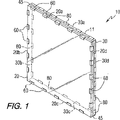
以下の説明では、同じ要素には、同じ参照番号を付ける。図1〜3を参照して、エレクトロクロミック窓アセンブリ10が描写されている。必要ではないものの、本発明の非限定的な1実施形態では、ほぼ対称の形状を有する。例えば、エレクトロクロミック窓アセンブリ10は、正方形または長方形の窓アセンブリであり得る。このような対称形の窓アセンブリは、建築用のグレイジング(例えば、ビル用の窓)として、特に有用である。エレクトロクロミック窓アセンブリ10の大きさおよび形状は、そのアセンブリの特定の所望用途に従って、選択できる。
In the following description, the same elements are given the same reference numerals. With reference to FIGS. 1-3, an
エレクトロクロミック窓アセンブリ10は、第一透明基板20および第二透明基板30を含む。このような基板は、エレクトロクロミック装置で使用する当該技術分野で公知の任意の材料(例えば、重合体材料、ガラス、金属など、およびこのような材料の組合せがあるが、これらに限定されない)から作製できる。本発明の非限定的な1実施形態では、基板20および30の一方または両方は、ガラス(例えば、フロートガラス)から作製される。さらに、第一基板20および第二基板30は、両方とも透明である。さらに、必要ではないものの、基板20および30の一方または両方が、着色または濃淡付けされる。本発明の非限定的な1実施形態では、航空機窓アセンブリ10に組み込んだ透明基板および被覆の各々は、少なくとも70%の視感透過率を有する。本明細書中で使用する「光透過率」および「視感透過率」との用語は、透過する可視光の全量の尺度を意味する。本明細書で提供される視感透過率データは、CIE標準発光体Aについて測定され、LTAとして示される。
The
第一基板20および第二基板30は、互いに関して実質的に平行に面した関係で、間隔を開けて配置され、それらの間でチャンバ41を規定する。このような関係は、間隔要素45により、達成できる。間隔要素45は、第一基板20と第二基板30との間で所望の間隔を維持できる任意の様式で、位置付けることができる。本発明の非限定的な1実施形態では、間隔要素45は、当該技術分野で公知のように、密封様式で、第一基板20および第二基板30の外縁に隣接したエレクトロクロミック窓アセンブリ10の周辺に伸長している。必要ではないものの、間隔要素45は、第一基板20および第二基板30の外縁から僅かに内向きに、位置付けることができる。このような位置付けは、第一および第二基板の僅かに突き出しを与え、これは、電気的接触を改良するために、下記のように、第一および第二基板29および39の一部を露出できる。間隔要素45は、任意の導電性材料から作成できる。本発明の非限定的な1実施形態では、要素45は、重合体材料(例えば、硬化可能有機重合体材料)であり、これらは、熱可塑性材料、熱硬化性材料、UV硬化樹脂材料、およびそれらの組合せであるが、それらに限定されない。エポキシ系有機密封材料は、密封要素45として、有用である。
The
第一基板20の周辺は、対向末端20aおよび20c(これらは、互いに対向している)ならびに、対向末端20bおよび20d(これらは、互いに対向している)を規定する。同様に、第二基板30は、対向末端30aおよび30cならびに、対向末端30bおよび30dを含む。
The periphery of the
第一基板20および第二基板30は、それぞれ、これらの基板の向かい合った主要面21および31で、それぞれ、第一導電性被覆29および第二導電性被覆39の形状で、透明導電性材料の層を備え付けている。第一および第二導電性被覆29および39は、可視光に対して実質的に透明な任意の材料であり得、これらの基板の表面によく結合し、このエレクトロクロミック装置および大気中にて、任意の材料による腐食に耐性であり、また、良好な導電性を有する。必要ではないものの、被覆29および39は、典型的には、1個またはそれ以上の金属または金属酸化物被覆を含み、これには、例えば、銀、金、酸化スズ、酸化インジウムスズ(ITO)、フッ素ドープ酸化スズ(FTO)、アンチモンドープ酸化スズ、ITO/金属/ITO(IMI)、およびそれらの組合せならびに、当該技術分野で公知の任意の他の材料があるが、これらに限定されない。導電性被覆53は、いくつかの周知の方法(熱分解、化学蒸着およびマグネトロンスパッタリングを含めて)のいずれかにより、塗布できる。第一および第二導電性被覆29および39は、同一または異なる材料から作成できる。本発明を限定せずに、本発明で有用な被覆には、導電性フッ素ドープ酸化スズ被覆ガラス(これは、「NESA(登録商標)の商標でPittsburgh,PennsylvaniaのPPG Industries,Inc.から入手できる)および導電性酸化インジウムスズ被覆ガラス(これは、「NESATRON(登録商標)の商標でPittsburgh,PennsylvaniaのPPG Industries,Inc.から入手できる)が挙げられる。
The
本発明の非限定的な1実施形態では、第一および第二導電性被覆29および39は、1〜10Ω/平方の範囲、例えば、2〜5Ω/平方の範囲のシート抵抗を有する。さらに、第一および第二導電性被覆29および39の厚さは、互いに対して同一または異なり得、その被覆厚さは、均一であり得る(すなわち、全体にわたって、ほぼ同じ厚さ)か、不均一であり得る(すなわち、この被覆厚さは、変動する)。本発明の非限定的な1実施形態では、これらの被覆は、同じほぼ均一な厚さを有し、これは、5,000Å〜50,000Å、例えば、13,000Å〜26,000Åの範囲である。
In one non-limiting embodiment of the invention, the first and second
エレクトロクロミック媒体40は、第一基板20と第二基板30との間で形成されたチャンバ41内に含まれる。エレクトロクロミック媒体40は、当該技術分野で公知の任意の種類の材料であり得、任意の公知形状であり得る(例えば、エレクトロクロミック液体、溶液、ゲル、半固形材料、重合体材料などであるが、これらに限定されない)。エレクトロクロミック媒体40は、色を規定する少なくとも1種のエレクトロクロミック化合物または染料を含有する。このような材料は、大きい電位を加えるにつれて、着色し、引き続いて、さらに暗い色になるか遮光することが、当該技術分野で周知である。その電位が遮断されるか逆にされるとき、その着色は、除去または漂白され、エレクトロクロミック媒体40を通って光が完全に透過できるようになる。
The
本発明の非限定的な1実施形態では、エレクトロクロミック媒体40は、液相型エレクトロクロミック媒体であり、ここで、イオン導電性電解質の溶液中に含有された物質は、電気化学的に還元または酸化したとき、その電解質中に残る(ゲルを含めて)。他の非限定的な実施形態では、エレクトロクロミック媒体40は、表面限局エレクトロクロミック媒体であり、ここで、導電性の電極に直接結合した物質またはその近傍に限局された物質は、電気化学的に還元または酸化したとき、結合または閉じ込められたままである。さらに他の非限定的な実施形態では、エレクトロクロミック媒体40は、電着型エレクトロクロミック媒体であり、ここで、イオン導電性電解質の溶液中に含有された物質は、電気化学的に還元または酸化したとき、導電性の電極上で、層を形成する。
In one non-limiting embodiment of the present invention, the
必要ではないものの、1実施形態では、エレクトロクロミック媒体40は、少なくとも1種のアノード性エレクトロクロミック化合物および少なくとも1種のカソード性エレクトロクロミック化合物を含有し、このアノード性化合物は、酸化可能物質に相当し、また、このカソード性化合物は、還元可能物質に相当する。このエレクトロクロミック媒体に電位を加えると、このアノード性エレクトロクロミック化合物は、酸化し、そしてカソード性エレクトロクロミック化合物は、同時に、還元する。このような同時の酸化および還元の結果、可視スペクトルにおいて、少なくとも1波長、吸収率が変わる。エレクトロクロミック媒体40中でのこのようなアノード性およびカソード性エレクトロクロミック化合物の組合せは、電位を加えると、それに関連した色を規定する。このようなカソード性エレクトロクロミック化合物は、一般的に、ビオロゲン染料と呼ばれ、また、このようなカソード性エレクトロクロミック化合物は、一般的に、フェナジン染料と呼ばれる。
Although not required, in one embodiment, the electrochromic medium 40 contains at least one anodic electrochromic compound and at least one cathodic electrochromic compound, which corresponds to an oxidizable material. In addition, this cathodic compound corresponds to a reducible substance. When an electric potential is applied to the electrochromic medium, the anodic electrochromic compound is oxidized and the cathodic electrochromic compound is simultaneously reduced. As a result of such simultaneous oxidation and reduction, the absorptance changes by at least one wavelength in the visible spectrum. Such a combination of anodic and cathodic electrochromic compounds in the
エレクトロクロミック媒体40はまた、他の物質を含有し、これらには、例えば、溶媒、光吸収剤、光安定化剤、熱安定化剤、酸化防止剤、増粘剤、粘度調節剤および類似の物質が挙げられるが、これらに限定されない。 The electrochromic medium 40 also contains other materials, such as solvents, light absorbers, light stabilizers, heat stabilizers, antioxidants, thickeners, viscosity modifiers and the like. Material, but not limited to.
必要ではないものの、本発明の非限定的な1実施形態では、被覆29および/または39の少なくとも1縁部は、それぞれ、基板20および/または30の縁部に少なくとも近接して、すなわち、アセンブリ10の周縁部11に(例えば、周縁部11の2インチまたは1インチまたは0.5インチ(5.08cm、または2.54cmまたは1.27cm))以内で、伸長している。図1〜3で示した本発明の特定の非限定的な1実施形態では、被覆29および39の全ての縁部は、アセンブリ20の周縁部11に少なくとも近接しており、非限定的な1実施形態では、被覆29および39の全ての縁部は、それらの対応する基板の縁部に伸長しており、それゆえ、アセンブリ10の周縁部11に伸長している。複数の第一間隔設備は、第一導電性被覆29と接触し、また、複数の第二間隔設備は、第二導電性被覆39と接触する。本発明の非限定的な1実施形態では、複数の第一間隔設備は、複数のバスバー60を含み、また、複数の第二間隔設備は、複数のバスバー80を含む。本発明を限定することなく、特定の1実施形態では、バスバー60は、アノード性バスバーであるのに対して、バスバー80は、カソード性バスバーである。このようなバスバー60および80は、DC電源(図1〜3では図示せず)と、それぞれ、第一および第二導電性被覆29および39との間で、電気接続を与える。このような電気接続は、任意の公知の様式で、確立できる。例えば、図3で示すように、アノード性バスバー60の各々は、ハンダ接合部64により、アノード性導電性ワイヤ65に接続できるのに対して、カソード性バスバー80の各々は、ハンダ接合部84により、カソード性導電性ワイヤ85に接続できる。このようにして、アノード性バスバー60には、正電流が流され、また、カソード性バスバー80には、負電流が流され、このエレクトロクロミックセル内にて、それらの間で電位が生じる。さらに、間隔アセンブリ45、ワイヤ65および85および/または接合部64および84を保護するために、エレクトロクロミック窓アセンブリ10の周縁部11には、外部カバーまたは断熱材(図示せず)を設けることができる。
Although not required, in one non-limiting embodiment of the present invention, at least one edge of the
図1〜3で示した本発明の特定の実施形態では、被覆29の縁部は、アセンブリ10の周縁部11に伸長し、そしてアノード性バスバー60(これらは、第一導電性被覆29と接触している)は、第一基板20の対向末端20aおよび20cに沿って、設けられる。このようにして、電源からの電流は、第一基板20の対向末端20aおよび20cに沿って、第一導電性被覆29の対向縁部に供給される。同様に、被覆39の縁部は、アセンブリ10の周縁部11に伸長し、そしてカソード性バスバー80(これらは、第二導電性被覆39と接触している)は、第二基板30の対向末端30bおよび30dに沿って、設けられる。このようにして、電源からの電流は、第二基板30の対向末端30bおよび30dに沿って、第二導電性被覆39の対向縁部に供給される。さらに、この電流が流される第一および第二被覆29および39の対向末端は、互いから間隔を開けて配置されている。何らかの特定の理論で束縛するともりはないが、これらの被覆の対向末端に電流を流すことにより、そして第一被覆の末端(これらは、正電流でエネルギーが加えられている)を第二被覆の末端(これらは、負電流でエネルギーが加えられている)から間隔を開けて配置することにより、そのエレクトロクロミックセルの全体にわたる電位の均一な適用が得られ、その結果、そのエレクトロクロミック媒体の均一な着色が生じ、虹彩効果が少なくなると考えられている。本明細書中で使用する「均一な着色」との用語は、電位を加えることで色が変わるエレクトロクロミック媒体の部分が、全て、ほぼ同じ様式で(例えば、ほぼ同時におよび/またはほぼ同じ速度で)変わることを意味する。
In the particular embodiment of the invention shown in FIGS. 1-3, the edge of the
本発明の他の非限定的な実施形態では、バスバー60は、対向縁部20aおよび20cに沿って配列されているならびに、対向縁部20bおよび20dに沿っても配列されており、また、バスバー80は、対向縁部30bおよび30dに沿って配列されているだけでなく、対向縁部30aおよび30cに沿っても配列されている。このようにして、アノード性バスバー60は、第一基板20全体の周辺で設けられ、また、カソード性バスバー80は、第二基板30全体の周辺で設けられ、すなわち、バスバー60および80は、アセンブリ10の全周縁部11に位置付けられる。図1〜3で示した特定の非限定的な1実施形態では、バスバー60およびバスバー80は、交互様式で配列され、すなわち、各バスバー60は、窓アセンブリ10の周縁部11で、各バスバー80間に配列される。このような配列により、電位は、エレクトロクロミック窓アセンブリ10全体にわたって、均一に適用される。必要ではないものの、本発明の非限定的な1実施形態では、各アノード性バスバー60は、少なくとも0.5インチ(1.27cm)の距離で、窓アセンブリ10の周縁部11に沿って、カソード性バスバー80から間隔を開けて配置されている。このような間隔を開けることにより、これらのバスバー間の電流は、短絡せず、そのエレクトロクロミック装置全体にわたって、均一な電位が得られる。それに加えて、このバスバーの構成により、電位を長期にわたって加えても、染料の分離が最小になる。染料の分離とは、典型的には、これらのバスバーに沿って、そのアセンブリのうち電力が最も高い部分に向かって移動して濃縮する染料の傾向である。
In other non-limiting embodiments of the invention, the bus bars 60 are arranged along the opposing
バスバー60および80は、バスバーに典型的に使用される当該技術分野で周知の任意の非常に導電性の材料から作製できる。典型的なバスバー材料の非限定的な例には、金属箔(例えば、銅箔)、金属被覆(例えば、金被覆)および導電性金属含有セラミック顔料(例えば、銀セラミック顔料)が挙げられる。 The bus bars 60 and 80 can be made from any highly conductive material known in the art typically used for bus bars. Non-limiting examples of typical busbar materials include metal foil (eg, copper foil), metal coating (eg, gold coating) and conductive metal-containing ceramic pigment (eg, silver ceramic pigment).
バスバー60および80の大きさおよび形状は、このエレクトロクロミック窓アセンブリの特定の外形に仕立てることができる。本発明の非限定的な1実施態様では、バスバー60および80の各々は、少なくとも0.5インチ(1.27cm)の長さである。 The size and shape of the bus bars 60 and 80 can be tailored to the specific profile of this electrochromic window assembly. In one non-limiting embodiment of the invention, each of the bus bars 60 and 80 is at least 0.5 inches (1.27 cm) long.
指摘したように、エレクトロクロミック媒体40は、その媒体に電位を加えたとき、その色を変えることができ、それゆえ、その光透過率を変えることができる。この電位の適用は、選択的であり得、すなわち、このエレクトロクロミック窓アセンブリは、電位を加えないときの1透過率レベルと、電位を加えて染料の色を変えエレクトロクロミック媒体40の視感透過率を低くしたときの第二透過率レベルとの間で、切替可能である。この特徴は、この窓アセンブリに電流を選択的に流すスイッチを設けることにより、最も簡単に達成される。
As indicated, the electrochromic medium 40 can change its color when an electric potential is applied to the medium, and therefore its light transmittance. The application of this potential can be selective, i.e., the electrochromic window assembly has one transmission level when no potential is applied and the luminous transmission of the
本発明の非限定的な1実施態様では、電気エネルギーを加えた状態と電気エネルギーを加えていない状態との間のエレクトロクロミック媒体の着色は、自己消去性であり、すなわち、電位を加えて電気化学的に起動した状態のときのエレクトロクロミック媒体の着色は、その電位を取り除くと、その初期状態(例えば、無色状態)に自動的に戻るか消去される。この初期状態は、無色状態であり得るか色または色合いを有し得ることが理解できるはずである。 In one non-limiting embodiment of the present invention, the coloring of the electrochromic medium between the state with and without electrical energy is self-erasable, i. The coloration of the electrochromic medium when in a chemically activated state automatically returns to or disappears from its initial state (eg, colorless state) when the potential is removed. It should be understood that this initial state can be colorless or have a color or shade.
さらに他の非限定的な実施態様では、このエレクトロクロミック窓アセンブリは、切替可能で非自己消去性であり、すなわち、電位を加えると、そのエレクトロクロミック媒体は、着色し、その電位を逆にするか短絡するまで、この着色状態のままとどまる。 In yet another non-limiting embodiment, the electrochromic window assembly is switchable and non-self-erasing, i.e., when an electric potential is applied, the electrochromic medium becomes colored and reverses the electric potential. Or stays in this colored state until shorted.
さらに、この染料の色は、電位を加えると、一定の暗さまたは陰影であり得るか、またはそのエレクトロクロミック媒体を通って確立された電位の規模に依存して、暗さまたは陰影の程度が変わり得る。例えば、本発明を限定することなく、特定の着色またはその着色の陰影は、一定の電圧または出力密度にわたって、変わり得る。このエレクトロクロミック媒体に低い出力密度を加えると、その染料は、着色し始め得る。その電圧を高めると、この染料の色は、さらに濃い陰影または強度まで暗くなり得る。このようにして、この窓アセンブリは、その電位を変えると、光透過率の程度を変えることを含み得る。この窓アセンブリは、従って、そこに加える電位の量に基づいて、所望レベルの暗さまたは陰影に調節できる。これは、例えば、後にさらに詳細に述べるように、電源と窓アセンブリとの間で、スイッチまたはある種の他の制御を組み込むことにより、簡単に達成できる。必要ではないものの、本発明の非限定的な1実施態様では、このエレクトロクロミック窓アセンブリは、1〜20%の範囲の最小LTAと60〜80%の範囲の最大LTAとの間で切替可能である。そういうものとして、このエレクトロクロミック窓アセンブリは、望ましいとき、窓用の不透明遮光部として、効果的に機能できる。 In addition, the color of the dye can be a constant darkness or shading when an electric potential is applied, or the degree of darkness or shading depends on the magnitude of the potential established through the electrochromic medium. It can change. For example, without limiting the invention, the particular color or shade of that color may vary over a constant voltage or power density. When low power density is applied to the electrochromic medium, the dye can begin to color. As the voltage is increased, the color of the dye can darken to a deeper shade or intensity. In this way, the window assembly may include changing the degree of light transmission as its potential is changed. The window assembly can therefore be adjusted to a desired level of darkness or shading based on the amount of potential applied thereto. This can be easily accomplished, for example, by incorporating a switch or some other control between the power source and the window assembly, as will be described in more detail later. Although not required, in one non-limiting embodiment of the invention, the electrochromic window assembly is switchable between a minimum LTA in the range of 1-20% and a maximum LTA in the range of 60-80%. is there. As such, the electrochromic window assembly can effectively function as an opaque shading for the window when desired.
図4および5では、非限定的な代替実施態様が示されている。この特定の実施態様では、エレクトロクロミック窓アセンブリ110は、略卵形窓の形状であり、これは、例えば、航空機の客室窓として、使用できる。必要ではないものの、本発明のこの特定の実施態様では、上記実施態様と同様に、この卵形窓は、対称形状を有する。類似の様式にて、エレクトロクロミック窓アセンブリ110は、間隔を開けて配置した第一基板120および第二基板130だけでなく、第一導電性被覆129、第二導電性被覆139およびそれらの間のエレクトロクロミック媒体140を含む。被覆129および139は、それぞれ、基板120および130の対向面に塗布され、そしてエレクトロクロミック媒体140は、これらの被覆の間に位置付けられる。基板120および130は、スペーサ145により分離される。
4 and 5, a non-limiting alternative embodiment is shown. In this particular embodiment, the
バスバー160aは、第一基板120の第一末端120aに沿って、第一導電性被覆129の縁部に接続され、また、バスバー160cは、第一基板120の対向第二末端120cに沿って、第一導電性被覆129の対向縁部に接続される。さらに、バスバー180bは、第二基板130の第一末端130bに沿って、第二導電性被覆139の縁部に接続され、そして、バスバー180dは、第二基板130の対向第二末端130dに沿って、第二導電性被覆139の対向縁部に接続されている。必要ではないものの、本発明の非限定的な1実施態様では、バスバー160aおよび160cは、アノードバスバーであるのに対して、バスバー180bおよび180dは、カソードバスバーである。バスバー160aおよび160cを通って被覆129の対向末端に電流を流し、そして、バスバー180bおよび180dを通って被覆139の対向末端に電流を流し、そして被覆139のエネルギーを加えた対向末端から間隔を開けて被覆129のエネルギーを加えた対向末端を配置すると、被覆139は、エレクトロクロミック媒体140を通る電位を発生し、均一な様式で、エレクトロクロミック媒体140の色を変える。
The
図4および5で描写した実施態様では、バスバー160および180の大きさおよび形状は、図1のバス配列と比べて、長さが長い。必要ではないものの、本発明の非限定的な1実施態様では、バスバー160および180の各々は、長さが等しく、また、バスバー160および180は、アセンブリ110の周縁部で、少なくとも0.5インチ(1.27cm)の間隔を開けて配置されている。
In the embodiment depicted in FIGS. 4 and 5, the size and shape of the bus bars 160 and 180 are longer in length compared to the bus arrangement of FIG. Although not required, in one non-limiting embodiment of the present invention, each of bus bars 160 and 180 are equal in length, and bus bars 160 and 180 are at least 0.5 inches at the periphery of
図6および7は、略対称長方形の非限定的なエレクトロクロミック窓アセンブリ210を示す。このようなアセンブリは、例えば、自動車のフロントガラス、後部窓またはサンルーフ、または建築用のグレイジングとして、有用であり得る。先の実施態様と類似の様式にて、エレクトロクロミック窓アセンブリ210は、間隔を開けて配置した第一基板220および第二基板230だけでなく、第一導電性被覆229、第二導電性被覆239およびエレクトロクロミック媒体240を含む。基板220および230の対向面には、それぞれ、被覆229および239が塗布され、これらの被覆の間には、エレクトロクロミック媒体240が位置付けられる。基板220および230は、スペーサ245により分離される。
FIGS. 6 and 7 illustrate a non-limiting
アセンブリ210は、さらに、バスバー260および280を含む。必要ではないものの、本発明のこの特定の実施態様では、バスバー260は、アノードバスバーであり、そしてバスバー280は、カソードバスバーである。アノードバスバー260aおよび260bは、第一基板220の第一末端220aに沿って、第一導電性被覆229の第一縁部に接続され、そして、バスバー260cおよび260dは、第二基板220の対向第二末端220cに沿って、第一導電性被覆229の対向末端に接続される。さらに、カソードバスバー280aは、アノードバスバー260aおよび260b間で間隔を開けた位置で、第二基板230の第一末端230aに沿って、第二導電性被覆239の第一縁部に接続され、そして、カソードバスバー280bは、アノードバスバー260cおよび260d間で間隔を開けた位置で、第二基板230の対向第二末端230cに沿って、第二導電性被覆239の第二対向末端に接続される。さらに、バスバー280cおよび280dは、第二基板230の第三末端230bで、第二導電性被覆239の第三縁部に接続され、そして、バスバー280eおよび280fは、第二基板230の対向第四末端230dで、第二導電性被覆239の対向第四縁部に接続される。バスバー260a、260b、260cおよび260dを通って被覆229の対向末端に電流を流すと、バスバー280a、280b、280c、280d、280eおよび280fを通って、被覆239の周辺で、エレクトロクロミック媒体240を通る電位が発生し、均一な様式で、エレクトロクロミック媒体240の色を変える。
必要ではないものの、図6および7で示した本発明の特定の非限定的な実施態様では、バスバー260および280は、長さが等しく、また、バスバー260および280は、少なくとも0.5インチ(1.27cm)離れて、アセンブリ210の周縁部で、間隔を開けて配置されている。
Although not required, in the particular non-limiting embodiment of the present invention shown in FIGS. 6 and 7, the bus bars 260 and 280 are equal in length and the bus bars 260 and 280 are at least 0.5 inches ( 1.27 cm) apart, spaced at the periphery of the
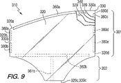
本発明のさらに別の非限定的な実施態様は、図8および9に示され、ここで、エレクトロクロミック窓アセンブリ310は、非対称形状を含む。このような非対称なエレクトロクロミック窓アセンブリは、任意の用途に提供できるのに対して、図示した特定の非限定的な実施態様は、自動車の横窓(これは、通例、サイドライトと呼ばれている)の形状である。エレクトロクロミック窓アセンブリ310は、第一部分301および第二部分302を含む。自動車のサイドライトとして使用する際に、第一部分301は、その窓アセンブリのうち、自動車のドアパネルの上にある部分に相当し、窓を閉じているときに見えるのに対して、第二部分302は、その窓アセンブリのうち、常に(窓を閉じたときを含めて)ドアパネルの下にとどまる部分に相当し、従って、見えない。エレクトロクロミック窓アセンブリ310は、先に述べた実施態様と同様に、間隔を開けて配置された第一基板320および第二基板330だけでなく、第一導電性被覆329、第二導電性被覆339およびエレクトロクロミック媒体340を含む。被覆329および339は、それぞれ、基板320および330の対向面に塗布され、これらの被覆の間には、エレクトロクロミック媒体340が位置付けられている。基板320および330は、スペーサ345により分離されている。
Yet another non-limiting embodiment of the present invention is shown in FIGS. 8 and 9, wherein the
エレクトロクロミックアセンブリ310は、バスバー360a(これは、第一基板320の第一末端320aに沿って、第一導電性被覆329の縁部に接続されている)およびバスバー360b(これは、対向第二末端320cの近くの第一基板320の下部に沿って、第一導電性被覆329に接続されている)を含む。バスバー360bは、基板320の縁部320cに沿って位置付けることができるものの、図8および9で示した本発明の特定の実施態様では、バスバー360bは、後にさらに詳細に述べる理由のために、縁部320cに沿って位置付けられない。エレクトロクロミックアセンブリ310は、さらに、バスバー380aおよび380b(これらは、第二基板330の第一末端330bに沿って、第二導電性被覆339の第一縁部に接続されている)およびバスバー380c、380dおよび380e(これらは、第二基板330の対向第二末端330dに沿って、第二導電性被覆339の対向第二縁部に接続されている)を含む。必要ではないものの、非限定的な1実施態様では、バスバー360aおよび360bは、アノードバスバーであるのに対して、バスバー380a、380b、380c、380dおよび380eは、カソードバスバーである。バスバー360a、360b、380a、380b、380c、380dおよび380eを通って被覆329および339に電流を流すと、エレクトロクロミック媒体340を通って、電位が発生し、エレクトロクロミック媒体340は、均一な様式で、色を変える。
The
述べたように、エレクトロクロミック窓アセンブリ310は、非対称形状を含む。特に、それぞれ、基板320および330の第一末端320bおよび330bで形成された窓アセンブリ310の側面は、第二末端320dおよび330dで形成された窓アセンブリ310の対向側面より、長さが短い。そういうものとして、この特定の非限定的な実施態様では、このバスバー配列は、このような非対称形状を補償するために、調節される。例えば、そのカソードバスバー配列に関して、2個のバスバー380aおよび380bは、末端330bに沿って、第二導電性被覆339と接触して、設けられるのに対して、3個のバスバー380c、380dおよび380eは、対向末端330dに沿って、第二導電性被覆339と接触して、設けられる。さらに、これらのバスバーの長さは、適当な取付および形状だけでなく適当なレベルの電流を供給するように、調節できる。異なる数および異なる長さのバスバーを備えたこのような配列は、エレクトロクロミック窓アセンブリ310が非対称形状であることから、そのエレクトロクロミック(electrochemical)セルを横切る電流について、補償する。
As stated, the
それに加えて、これらのバスバーに流された電流は、その非対称形状を補償するために、調節できる。例えば、本発明を限定することなく、これらのバスバーに流れる電流の量を少なくするために、バスバー380aおよび380bへの電流の流れには、抵抗器(図示せず)を組み込むことができる。そういうものとして、補償は、この非対称アセンブリに加えた電位に対して、行われる。代案として、後にさらに詳細に述べるように、各バスバーに送達された電流を制御するために、制御装置が使用できる。
In addition, the current passed through these bus bars can be adjusted to compensate for its asymmetric shape. For example, without limiting the present invention, resistors (not shown) may be incorporated into the current flow to
図8および9を引き続いて参照すると、窓アセンブリ310の上縁(これは、第一末端320aおよび330aにより、形成される)は、均一であり、僅かに曲がっているにすぎないのに対して、窓アセンブリ310の対向縁部(これは、第二末端320cおよび330cにより、形成される)は、全く不均一であり、曲線部分および直線部分を有し、その結果、異なる部分で対向縁部間の距離が変わる非対称形状窓アセンブリが得られる。そういうものとして、この窓アセンブリのこの部分でのバスバーの配列は、困難である。このような非対称形状を補償するために、図8および9で示した本発明の特定の実施態様では、第一導電性被覆329と電気接触して、単一バスバー360bが設けられる。このような内部バスバー360bは、例えば、基板320に沿って、導電性接着剤を使って、第一導電性被覆329にバスバー360bを接着剤で接着することにより、設けることができる。バスバー360bの上には、絶縁体として作用するように、非導電層(図示せず)(例えば、接着テープがあるが、これに限定されない)が設置でき、バスバー360bが第二導電性被覆339と電気接触するのを防止する。このような接着テープは、さらに、スペーサとして作用でき、第一基板320と第二基板330との間で、適当な間隔を維持する。内部バスバー360Bは、他のバスバーについて先に述べた材料と同じ材料から作製できる。
With continued reference to FIGS. 8 and 9, the upper edge of the window assembly 310 (which is formed by the first ends 320a and 330a) is uniform and only slightly bent. , The opposing edges of the window assembly 310 (which are formed by the second ends 320c and 330c) are quite uneven and have curved and straight portions, so that the opposing edges at different portions Asymmetrically shaped window assemblies with varying distances between them are obtained. As such, the arrangement of the bus bars at this part of the window assembly is difficult. To compensate for such an asymmetric shape, in the particular embodiment of the present invention shown in FIGS. 8 and 9, a
結果として、本発明の非限定的な1実施態様では、このエレクトロクロミックアセンブリは、そのアセンブリの縁部から間隔を開けて配置されかつアセンブリ内に位置している少なくとも1個のバスバーを含む。 As a result, in one non-limiting embodiment of the invention, the electrochromic assembly includes at least one bus bar spaced from and located within the assembly edge.
必要ではないものの、図8および9で示す本発明の特定の実施態様では、内部バスバー360bの一部361bは、図8および9で示すように、例えば、縁部320cに対して垂直に、窓310の縁部に向かって伸長して、バスバー360bを電源に電気接続するための導電性ワイヤとの外部接触が得られる。この内部バスバー配置は、窓アセンブリ300の一部302内に含まれるので、部分302が自動車のドアパネル内で維持されているとき、それらの部品のいずれも見えない。代案として、バスバー360bの少なくとも一部は、アセンブリ300のセクション301内に位置付けることができる。
Although not required, in the particular embodiment of the present invention shown in FIGS. 8 and 9, a
図8〜9で示す自動車用サイドライトに関して、代替実施態様では、そのバスバー接点は、この窓アセンブリの外側上部および側縁部に設けることができ、別の接点は、電源との接触を確立するために、その自動車のフレーム内に設けられることが注目される。この配置は、自動車窓用の適当なアセンブリを提供し、これは、このような配置において、これらの接点を隠す外部カバーが存在しないので、この自動車窓は、ドアのフレーム内に覆われない。このような配置は、その窓を閉じると電源と接触可能となるので、また、この窓を開けるとき、窓を遮光する必要がないので、この窓アセンブリを暗くすることに対して、有害ではない。 With respect to the automotive sidelights shown in FIGS. 8-9, in an alternative embodiment, the bus bar contacts can be provided on the outer top and side edges of the window assembly and another contact establishes contact with the power source. Therefore, it is noted that it is provided in the frame of the automobile. This arrangement provides a suitable assembly for the automobile window, which is not covered within the door frame because in this arrangement there is no outer cover that hides these contacts. Such an arrangement is not detrimental to darkening the window assembly, since closing the window makes contact with the power source, and when opening the window, there is no need to shade the window. .
このエレクトロクロミック窓アセンブリに流す電流の量は、使用する特定のアセンブリおよび特定のエレクトロクロミック媒体に基づいて、選択できる。本発明の非限定的な1実施態様では、流す電流の量は、0.4ボルト〜1.2ボルトの範囲、例えば、0.5ボルト〜1.0ボルトの範囲である。 The amount of current passed through the electrochromic window assembly can be selected based on the particular assembly used and the particular electrochromic medium. In one non-limiting embodiment of the present invention, the amount of current passed is in the range of 0.4 volts to 1.2 volts, for example in the range of 0.5 volts to 1.0 volts.
このエレクトロクロミック窓アセンブリの使用は、今ここで、本発明の代表的なものとして、図8〜9を特に参照して、記述する。上記エレクトロクロミック窓アセンブリは、そこに電位を加えないとき、ほぼ透明のアセンブリである。そういうものとして、エレクトロクロミック窓アセンブリ310は、明るくした状態であり、完全な光透過率が可能である。この窓アセンブリを暗くするのが望ましいとき、このエレクトロクロミック窓アセンブリは、例えば、ユーザーが起動可能なスイッチにより、起動される。このスイッチを起動すると、その電源は、任意の便利な様式で(例えば、そこに装着されたワイヤリード線を通って)、第一および第二導電性被覆329および339へと、バスバー360および380に電流が供給される。このような電流により、このエレクトロクロミック媒体に電位が加わり、これは、順に、少なくとも1種のアノードエレクトロクロミック化合物が酸化され、そして、少なくとも1種のカソードエレクトロクロミック(electrochemical)化合物が還元される。この反応により、このエレクトロクロミック媒体の色が変わり、そのエレクトロクロミック媒体が光を吸収して暗くなり始める。被覆329と339との間の電位は、上で述べたように、このバスバー配列を通って加えられるので、このエレクトロクロミック媒体の着色は、虹彩効果も漸次の色変化なく、このエレクトロクロミック窓アセンブリ全体にわたって、急速かつ均一である。
The use of this electrochromic window assembly will now be described as representative of the present invention, with particular reference to FIGS. The electrochromic window assembly is a substantially transparent assembly when no potential is applied thereto. As such, the
アセンブリ310を停止すると、バスバー360および380への出力の供給が中断する。そういうものとして、エレクトロクロミック媒体340に加えられた電位は、取り除かれる、このような停止は、上で述べたアセンブリ310を起動する同じスイッチ配列を使用して、行うことができる。以前に述べたように、自己消去性エレクトロクロミック媒体の場合、窓アセンブリ310は、その初期状態に戻る。非自己消去性エレクトロクロミック媒体の場合、その色は、この媒体を通る電位が逆になるまで、残る。
When the
本発明のさらに他の実施態様では、このエレクトロクロミック窓アセンブリの一部だけが着色でき、部分遮光窓を確立する。このような部分遮光は、選択した数のアノードバスバーおよびカソードバスバーに電流を選択的に流すことにより達成でき、それにより、このエレクトロクロミック窓アセンブリの一部だけを通る電位が作り出される。例えば、このような窓アセンブリ310が自動車のサイドライトの形状であるとき、例えば、サイドミラーをより見やすくするために、そのサイドライトの中間部および下部を明るい状態で維持して、そこを通る光の透過率を高いレベルに維持しつつ、このサイドライトの暗くしたまたは遮光した上部領域を作り出して、そこを通って透過する日光のレベルを少なくすることが望まれ得る。図8および9で示した本発明の特定の実施態様では、このような優先的な領域遮光は、例えば、後にさらに詳細に述べるように、アノードバスバー360aならびにカソードバスバー380aおよび380cだけに電流を通すことにより、達成できる。このように選択的に電流を流すことにより、エレクトロクロミック窓アセンブリ310の選択部分のみで、この特定の実施態様では、アセンブリ310の上部に沿って、電位が確立される。そういうものとして、これらの領域間にある、電流を流したエレクトロクロミック媒体の一部だけが色が変わり、結果として、部分遮光アセンブリが得られ、すなわち、(これらのバスバーに選択的に出力を加えることで)、これらの被覆のエネルギーを加えた部分間にあるエレクトロクロミック媒体の一部を通る視感透過率は、それらの被覆のエネルギーを加えた部分の間にはないエレクトロクロミック媒体の部分と比較して、変わる。
In yet another embodiment of the present invention, only a portion of this electrochromic window assembly can be colored to establish a partially shaded window. Such partial shading can be accomplished by selectively passing current through a selected number of anode bus bars and cathode bus bars, thereby creating a potential through only a portion of the electrochromic window assembly. For example, when such a
このようにして選択数の設備に電流を長期間加えると、そのエレクトロクロミック媒体の「浸出」が起こり得、ここで、このエレクトロクロミック窓アセンブリのうち、電流が流されない領域にあるエレクトロクロミック媒体は、徐々に、暗い状態に着色し始めることが注目される。これは、その電流が導電層の一部にだけ流されたとしても、この導電層全体を通って流れる電流が原因であると考えられ、それゆえ、その電位が加えられるエレクトロクロミック媒体の流域が拡大する。浸出の量は、この導電性被覆のシート比抵抗に基づいている。例えば、シート抵抗がより高い導電性被覆を組み込むと、この浸出効果がある程度低くなる。しかしながら、シート抵抗が高いなら、その装置の色を切り替えるのに、より多くの出力を消費し、この装置を完全に着色し切り替えるには、より長い時間がかかる。 Thus, when current is applied to a selected number of facilities for a long period of time, the electrochromic medium can “leach”, where the electrochromic medium in a region of the electrochromic window assembly in which no current flows is It is noticed that gradually, it begins to color in a dark state. This can be attributed to the current flowing through the entire conductive layer, even if the current is only applied to a portion of the conductive layer, and therefore the basin of the electrochromic medium to which the potential is applied. Expanding. The amount of leaching is based on the sheet resistivity of this conductive coating. For example, incorporating a conductive coating with higher sheet resistance will reduce this leaching effect to some extent. However, if the sheet resistance is high, more power is consumed to switch the color of the device, and it takes longer to fully color and switch the device.
特に、シート抵抗が低い導電性被覆を使って、この浸出効果を避けるために、遮光領域を作り出すために電流を加えるようには選択されていない設備にて、この電流を接地または短絡することが可能である。例えば、上で述べたように、図8および9では、この部分遮光窓アセンブリは、アノードバスバー360aとカソードバスバー380aおよび380cとに電流を選択的に流すことにより、達成できる。残りのバスバー(すなわち、アノードバスバー360bおよびカソードバスバー380b、380dおよび380e)にて、この電流を接地または短絡することにより、エレクトロクロミック窓アセンブリ310の下部領域には、電位が加わらない。それゆえ、エレクトロクロミック媒体340の色は、アセンブリ310の下部では、一般に、明るい状態で維持され、電位を加えたことが原因で着色した上部からの色の浸出効果が維持される。
In particular, using a conductive coating with low sheet resistance, to avoid this leaching effect, this current may be grounded or shorted in equipment that is not selected to apply current to create a light-shielding area. Is possible. For example, as described above, in FIGS. 8 and 9, this partial light blocking window assembly can be achieved by selectively passing current through the
さらに、このエレクトロクロミック窓アセンブリは、その表面を横切る勾配遮光を含むことができ、その結果、そのエレクトロクロミック窓アセンブリは、明るい状態から、順次暗くなった遮光領域を経て、暗くなった状態まで、徐々に変化する。これは、そのエレクトロクロミック媒体を暗くする程度を変えるために、異なる設備に対して加える電圧を変えることにより、優先的遮光領域に関して上で記述した様式と類似の様式で、達成できる。例えば、図8および9をさらに参照すると、本発明の非限定的な1実施態様にて、徐々に変化する遮光効果を達成するために、バスバー360a、380aおよび380cには、0.7ボルトの電圧を加えることができ、そして、バスバー380bおよび380dには、それより低い0.4ボルトの電圧を加えることができる。必要ではないものの、その電流は、さらに、バスバー360bおよび380eで接地または短絡できる。そういうものとして、エレクトロクロミック窓アセンブリ310は、その上部における暗い状態から、その中間部での僅かに暗い状態を経て、その下部での明るい状態へと、徐々に遮光できる。
In addition, the electrochromic window assembly can include gradient shading across its surface, so that the electrochromic window assembly passes from a bright state to a darkened state through sequentially darkened shading areas. Change gradually. This can be accomplished in a manner similar to that described above for the preferential light-shielding region by changing the voltage applied to the different equipment to change the degree of darkening of the electrochromic medium. For example, with further reference to FIGS. 8 and 9, in one non-limiting embodiment of the present invention, to achieve a gradually changing shading effect,
本発明の他の非限定的な実施態様では、そのエレクトロクロミック窓アセンブリを横切って勾配を付けた遮光を達成することが可能であり、その結果、このエレクトロクロミック窓アセンブリの一部は、完全に着色されるのに対して、そのエレクトロクロミック窓アセンブリの別の部分は、部分的に着色されるにすぎない。例えば、本発明を限定することなく、バスバー360a、380aおよび380cには、0.7ボルトの電圧を加えることができるのに対して、バスバー360b、380b、380dおよび380eには、0.4ボルトの電圧が加えられる。そういうものとして、エレクトロクロミック窓アセンブリ310は、その上部での完全に遮光した状態から、その下部での僅かに遮光した状態を経た徐々に変化する遮光を含む。
In another non-limiting embodiment of the present invention, it is possible to achieve a light-shielding gradient across the electrochromic window assembly so that a portion of the electrochromic window assembly is fully In contrast to being colored, another part of the electrochromic window assembly is only partially colored. For example, without limiting the present invention, a voltage of 0.7 volts can be applied to
このエレクトロクロミック窓アセンブリのこのような優先的な遮光および/または徐々に変化する勾配遮光は、自動車のサイドライトに関して、図8および9の形状を特に参照して述べられていることが注目され、このような遮光または勾配遮光は、任意のエレクトロクロミック窓アセンブリを使って達成できると考えられ、これには、上述の特定のアセンブリがあるが、これに限定されない。例えば、非限定的な特定の1実施態様では、このエレクトロクロミック窓アセンブリは、自動車のフロントガラスであり、そのアセンブリのうち、選択的に着色される部分は、フロントガラスの上縁部であり、これは、典型的には、その遮光バンドに相当する。図6および7を参照すると、これは、例えば、バスバー260c、260d、280b、280dおよび280fを短絡させつつ、バスバー260a、260b、280a、280cおよび280eに電流を流すことにより、達成できる。これにより、エレクトロクロミック窓アセンブリ200の上部は、暗くなり、その下部は、明るい状態のままとどまる。
It is noted that such preferential shading and / or gradual gradient shading of this electrochromic window assembly has been described with particular reference to the shapes of FIGS. 8 and 9 with respect to automobile sidelights, Such shading or gradient shading could be achieved using any electrochromic window assembly, including but not limited to the specific assemblies described above. For example, in one specific, non-limiting embodiment, the electrochromic window assembly is an automotive windshield, and the selectively colored portion of the assembly is the upper edge of the windshield, This typically corresponds to the shading band. Referring to FIGS. 6 and 7, this can be accomplished, for example, by passing current through
さらに他の実施態様では、このエレクトロクロミック窓アセンブリは、自動車のサンルーフであり得、そのアセンブリの一面が選択的に着色される。図6および7を参照すると、これは、例えば、バスバー260b、260d、280a、280b、280eおよび280fを短絡しつつ、バスバー260a、260c、280cおよび280dに電流を流すことにより達成でき、エレクトロクロミック窓アセンブリ200の一方の側面部は、暗くなり、他の側面部は、明るい状態のままとどまる。
In yet another embodiment, the electrochromic window assembly can be an automobile sunroof, and one side of the assembly is selectively colored. Referring to FIGS. 6 and 7, this can be achieved, for example, by passing current through
図1で示し上で詳細に述べたように、窓アセンブリ10の周縁部11に位置付けられた複数のアノードバスバーおよびカソードバスバーのために、この実施態様はまた、アセンブリ10の1個またはそれ以上の選択した部分を暗くするかおよび/またはアセンブリ10の1個またはそれ以上の選択した部分で勾配遮光を生じる様式で、操作できることが分かる。
As shown in FIG. 1 and described in detail above, for a plurality of anode bus bars and cathode bus bars positioned at the
本明細書中で開示した種類のエレクトロクロミック窓アセンブリが暗くなるパターンを制御するために、これらの導電性被覆の出力分布を制御するのに、制御装置が使用できる。例えば、図10を参照して、制御装置390は、DC電源391により、アセンブリ310内の各バスバーに供給された電力を制御するのに、使用できる。さらに特定すると、制御装置390は、特定のバスバーにエネルギーが加えられるか(すなわち、そのバスバーに電流が送達されるか)、エネルギーが加えられていないか、または短絡されるかを制御できる。それに加えて、制御装置390は、特定のバスバーにどの程度の電流を送達するかを制御できる。これらの被覆にどこでどの程度の電流を供給すべきかを制御することにより、制御装置390は、このエレクトロクロミック媒体の選択部分だけを通る電位を確立でき、その結果、その選択部分を通る視感透過率は、その他の部分を通る視感透過率とは異なる。結果として、制御装置390は、このアセンブリの視感透過率に所望の変化(例えば、そのアセンブリの選択部分を暗くすること、または以前に述べたように、勾配遮光を提供することがあるが、これらの限定されない)を生じるために、使用できる。制御装置390はまた、必要に応じて、そのアセンブリの非対照的な特徴(例えば、形状、バスバーの長さ、被覆厚など)を考慮して、その電流を制御できる。
Controllers can be used to control the power distribution of these conductive coatings to control the darkening pattern of an electrochromic window assembly of the type disclosed herein. For example, referring to FIG. 10,
本発明の特徴および利点は、以下の実施例によって、さらに記述され理解され、これらは、本発明の範囲を限定するとは解釈されない。 The features and advantages of the invention will be further described and understood by the following examples, which are not to be construed as limiting the scope of the invention.
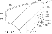
自動車の横窓またはサイドライトの形状のエレクトロクロミック窓アセンブリ410を、以下のようにして、作成した。図11の形状を有する第一ガラス基板420(全体的な大きさは、幅23インチ(58.42cm)および長さ21インチ(53.34cm)であり、約80ミル(2.03mm)の厚さを有する)を提供した。この第一基板420の一面に、マグネティックスパッタ蒸着(MSVD)技術(これは、導電層を設ける分野で周知である)を使用して、ITOの被覆429を被覆した。導電性被覆429の抵抗は、2Ω/平方であり、その導電性被覆を、25,000Åの厚さまで被覆した。第一ガラス基板420と類似した第二ガラス基板430に、類似の様式で、導電性被覆439を設けたが、導電性被覆439は、第一ガラス基板420の被覆面に面する第二基板430の表面に塗布した。
An
第一導電性被覆429の対向縁部に、アノード性バスバーを設けた。さらに特定すると、3ミル厚の銅箔ストリップ(これらは、導電性接着剤により、第一導電性被覆429に固定した)を使用して、第一基板420の上縁を横切って、第一対のアノード性バスバー460aおよび460bを設けた。アセンブリ410内に、各ストリップの一部を積層し、各ストリップの残りを、第一基板420の縁部の周りに巻き付けた。バスバー460aおよび460bの長さは、それぞれ、10.5インチおよび10.25インチ(26.67cmおよび26.04cm)であり、0.5インチ(1.27cm)だけ分離されていた。第三アノード性バスバー460cは、3ミル厚の銅の別のストリップにより設けたが、これは、第一導電性被覆429に、直接、第一基板420の下部を横切って接着し、銅の別のストリップ461cもまた、バスバー460cと垂直にそれと接触して、第一導電性被覆に直接接着し、これは、窓アセンブリ410の縁部に伸長している。バスバー460cおよびストリップ461cの上には、絶縁体として、接着テープを設けた。バスバー460cの長さは、20.5インチ(52.07cm)であった。
An anodic bus bar was provided at the opposite edge of the first
第二導電性被覆439と接触して、第二基板430の対向縁部には、4個のカソード性バスバーを設けた。さらに特定すると、第二導電性被覆439の第一縁部と接触して、2個の別々の銅ストリップ(これらは、互いから0.5インチ(1.27cm)の間隔を開けて配置されている)の形状で、第二基板430の1側縁部を横切って、カソード性バスバー480aおよび480bを設け、また、第二導電性被覆439の対向縁部と接触して、2個の別々の追加銅ストリップ(これらは、互いから0.5インチ(1.27cm)の間隔を開けて配置されている)の形状で、第二基板430の対向1側縁部を横切って、カソード性バスバー480cおよび480dを設けた。これらのバスバーの各々は、3ミル厚の銅箔から作製し、そして導電性接着剤により、各個の導電性被覆に固定した。各ストリップの一部を、アセンブリ410内に積層し、各ストリップの残りを、第二基板430の縁部の周りに巻き付けた。バスバー480a、480b、480cおよび480dは、それぞれ、長さ4.25インチ、7.25インチ、4.25インチおよび11.75インチ(10.80cm、18.42cm、10.80cmおよび29.85cm)であった。
In contact with the second
2枚のガラス基板420および430を、約24ミル(0.61mm)の間隔を開けて配置し、導電性被覆429および439を、互いに向かい合わせた。これらの2枚の基板間で、このアセンブリの周辺には、スペーサとして作用するために、重合体樹脂を塗布した。これらの2枚の基板間に、そこに電位を加えると着色し得るエレクトロクロミック媒体440(これは、ビオロゲン染料およびフェナジン染料を含有する)を注入した。非荷電状態(すなわち、電流を流さない)で、エレクトロクロミック窓アセンブリ410を通る視感透過率(LTA)は、約54%であった。
Two
これらのアノード性およびカソード性バスバーを、ワイヤリード線を通って、DC電源に接続した。以下で示すように、異なるセットのバスバーに対して、種々のレベルの電流を流した。バスバー480aおよび480bに沿ったアセンブリ410の縁部は、そのアセンブリの対向縁部よりも短いので、バスバー480aおよび480bの線に沿って、0.5Ω抵抗器を挿入して、その電流を変え、ほぼ均一な出力密度を得た。
These anodic and cathodic busbars were connected to a DC power source through wire leads. As shown below, different levels of current were applied to different sets of bus bars. Since the edge of

実施例2では、窓アセンブリ410の上部に配列したアノード性およびカソード性バスバー(具体的には、アノード性バスバー460aおよび460b、およびカソード性バスバー480aおよび480c)にのみ、0.70ボルトで、電流を流した。5分後、このエレクトロクロミック窓アセンブリは、0.065アンペアで、定常状態に達し、ここで、その酸化/還元反応の全ては、このエレクトロクロミック媒体内にて、そのアノード性染料とカソード性染料との間で、起こった。表Iで分かるように、このエレクトロクロミック窓アセンブリの上部は、優れた着色に達し、<1%のLTAを有していた。このアセンブリの下部は、約6〜7%のLTAを有していた。それゆえ、この窓アセンブリの着色または暗化は、不均一であり、その上部から下部を見ると、勾配があった。
In Example 2, only anodic and cathodic busbars (specifically,
実施例3では、窓アセンブリ410の上部に配列したアノード性およびカソード性バスバー(具体的には、アノード性バスバー460aおよび460b、およびカソード性バスバー480aおよび480c)にのみ、0.70ボルトで、電流を流した。さらに、残りのアノード性およびカソード性バスバー、すなわち、アノード性バスバー460cおよびカソード性バスバー480bおよび480dは、短絡し、すなわち、エネルギーを加えたバスバーから、それらの導電性被覆を通って、これらのバスバーに達する電流は、取り除かれた。5分後、このエレクトロクロミック窓アセンブリは、0.154アンペアで、定常状態に達し、ここで、その酸化/還元反応の全ては、このエレクトロクロミック媒体内にて、そのアノード性染料とカソード性染料との間で、起こった。表Iで分かるように、このエレクトロクロミック窓アセンブリの上部は、部分着色に達し、14%のLTAを有していた。このアセンブリの下部は、約54%のLTAを有しており、これは、色変化なしに相当し、そのアセンブリの下部を通る完全な透過に相当していた。それゆえ、この窓アセンブリの上部を横切って、部分遮光バンドに達し、この遮光バンドを通って、少量の光が透過した。
In Example 3, only the anodic and cathodic busbars arranged at the top of the window assembly 410 (specifically,
実施例4では、実施例3と同様であるが0.80ボルトで、窓アセンブリ410の上部に配列したアノード性およびカソード性バスバー(具体的には、アノード性バスバー460aおよび460b、およびカソード性バスバー480aおよび480c)にのみ、電流を流した。この場合もやはり、実施例3と同様に、残りのアノード性およびカソード性バスバー、すなわち、アノード性バスバー460cおよびカソード性バスバー480bおよび480dは、短絡した。5分後、このエレクトロクロミック窓アセンブリは、0.187アンペアで、定常状態に達し、ここで、その酸化/還元反応の全ては、このエレクトロクロミック媒体内にて、そのアノード性染料とカソード性染料との間で、起こった。表Iで分かるように、このエレクトロクロミック窓アセンブリの上部は、優れた着色に達し、約3%のLTAを有していた。他方、このアセンブリの下部は、約54%のLTAを有しており、これは、色変化なしに相当し、そのアセンブリの下部を通る完全な透過に相当していた。それゆえ、この窓アセンブリの上部を横切って、完全な遮光バンドが得られた。
Example 4 is similar to Example 3, but at 0.80 volts and is arranged at the top of the
本発明の実施例としての実施態様を記述した。これらの実施例は、単に、本発明の例示にすぎないことが分かる。本発明の多くの変更および改良は、当業者に明らかであり、上記請求の範囲の範囲内に含まれると解釈される。 An exemplary embodiment of the invention has been described. It will be appreciated that these examples are merely illustrative of the invention. Many variations and modifications of this invention will be apparent to those skilled in the art and are intended to be included within the scope of the following claims.
Claims (33)
第一透明基板であって、該第一透明基板は、その表面に第一導電性被覆を含む;
第二透明基板であって、該第二透明基板は、その表面に第二導電性被覆を含み、該第一透明基板および該第二透明基板は、互いに間隔を開けて配置されて、それらの間でチャンバを規定する;
エレクトロクロミック媒体であって、該エレクトロクロミック媒体は、該チャンバに含まれ、該エレクトロクロミック媒体は、該エレクトロクロミック媒体を通って電位を加えると変わる視感透過率を有する;
複数の第一間隔設備であって、該複数の第一間隔設備は、該第一導電性被覆と接触し、そして該第一導電性被覆に電流を送達できる;
複数の第二間隔設備であって、該複数の第二間隔設備は、該第二導電性被覆と接触し、そして該第二導電性被覆に電流を送達して、該エレクトロクロミック媒体を通る該電位を確立できる;
複数の第一接続部材であって、該複数の第一接続部材の各々は、該複数の第一間隔設備の対応する少なくとも1つに個別にかつ分かれて接続されて、該複数の第一間隔設備の対応する少なくとも1つに電流を送達する;および
複数の第二接続部材であって、該複数の第二接続部材の各々は、該複数の第二間隔設備の対応する少なくとも1つに個別にかつ分かれて接続されて、該複数の第二間隔設備の対応する少なくとも1つに電流を送達する、
窓アセンブリ。Electrochromic window assembly, including:
A first transparent substrate, the first transparent substrate including a first conductive coating on a surface thereof;
A second transparent substrate, the second transparent substrate including a second conductive coating on a surface thereof, the first transparent substrate and the second transparent substrate being spaced apart from each other, and Define chambers between them;
An electrochromic medium, wherein the electrochromic medium is contained in the chamber, the electrochromic medium having a luminous transmittance that changes upon application of an electric potential through the electrochromic medium;
A plurality of first spacing devices, wherein the plurality of first spacing devices can contact and deliver current to the first conductive coating;
A plurality of second spacing devices, wherein the plurality of second spacing devices are in contact with the second conductive coating and deliver current to the second conductive coating to pass through the electrochromic medium. Potential can be established;
A plurality of first connection members, each of the first connecting member of said plurality of, connected to at least one individually and divided by the corresponding first gap facilities the plurality of first distance of the plurality of delivering at least one current corresponding equipment; and a plurality of second connecting members, each of the plurality of second connecting members, the individual to at least one corresponding second interval facility plurality of And separately connected to deliver current to at least one corresponding one of the plurality of second spacing facilities.
Window assembly.
エレクトロクロミック窓アセンブリを提供する工程であって、該エレクトロクロミック窓アセンブリは、第一および第二間隔透明基板を含み、該第一および第二間隔透明基板は、それらの間でチャンバを規定し、該第一透明基板は、第一導電性被覆を有し、そして該第二透明基板は、第二導電性被覆を有し、該チャンバは、そこに電位を加えると着色して視感透過率を低下させ得るエレクトロクロミック媒体を含有する;
該第一導電性被覆に該電位を与えるために、該第一導電性被覆に複数の第一間隔設備を電気接続する工程;
該第二導電性被覆に該電位を与えるために、該第二導電性被覆に複数の第二間隔設備を電気接続する工程;
該複数の第一間隔設備の選択したものおよび該複数の第二間隔設備の選択したものに電流を流して、該エレクトロクロミック媒体の選択部分を通って該電位を確立し、該選択部分が色を変えその視感透過率を低下させるようにする工程
を包含する、方法。A method of preferentially coloring a portion of an electrochromic window assembly, the method comprising the following steps:
Providing an electrochromic window assembly, the electrochromic window assembly including first and second spaced transparent substrates, the first and second spaced transparent substrates defining a chamber therebetween; The first transparent substrate has a first conductive coating, and the second transparent substrate has a second conductive coating, and the chamber is colored when a potential is applied thereto, and the luminous transmittance. Containing an electrochromic medium capable of lowering
Electrically connecting a plurality of first spacing equipment to the first conductive coating to apply the potential to the first conductive coating;
Electrically connecting a plurality of second spacing devices to the second conductive coating to apply the potential to the second conductive coating;
A current is passed through a selection of the plurality of first spacing equipment and a selection of the plurality of second spacing equipment to establish the potential through a selected portion of the electrochromic medium, the selected portion being colored And changing the luminous transmittance to reduce the luminous transmittance .
Applications Claiming Priority (2)
| Application Number | Priority Date | Filing Date | Title |
|---|---|---|---|
| US09/919,151 US6471360B2 (en) | 2000-08-03 | 2001-07-31 | Switchable electrochromic devices with uniform switching and preferential area shading |
| PCT/US2002/020744 WO2003012541A2 (en) | 2001-07-31 | 2002-07-01 | Switchable electrochromic devices |
Publications (3)
| Publication Number | Publication Date |
|---|---|
| JP2004537755A JP2004537755A (en) | 2004-12-16 |
| JP2004537755A5 JP2004537755A5 (en) | 2007-03-01 |
| JP3944165B2 true JP3944165B2 (en) | 2007-07-11 |
Family
ID=25441593
Family Applications (1)
| Application Number | Title | Priority Date | Filing Date |
|---|---|---|---|
| JP2003517667A Expired - Fee Related JP3944165B2 (en) | 2001-07-31 | 2002-07-01 | Switchable electrochromic device |
Country Status (9)
| Country | Link |
|---|---|
| US (2) | US6471360B2 (en) |
| EP (1) | EP1417535B1 (en) |
| JP (1) | JP3944165B2 (en) |
| CN (1) | CN1308761C (en) |
| AU (1) | AU2002346012A1 (en) |
| BR (1) | BR0211854A (en) |
| DE (1) | DE60207730T2 (en) |
| RU (1) | RU2262729C2 (en) |
| WO (1) | WO2003012541A2 (en) |
Families Citing this family (125)
| Publication number | Priority date | Publication date | Assignee | Title |
|---|---|---|---|---|
| WO2002039180A1 (en) * | 2000-11-10 | 2002-05-16 | Murakami Corporation | Solid state electrochromic element and mirror device and crt display comprising it |
| US6798556B2 (en) * | 2003-01-31 | 2004-09-28 | Rockwell Scientific Licensing, Llc. | Locally-switched reversible electrodeposition optical modulator |
| EP1608719A2 (en) * | 2003-03-05 | 2005-12-28 | Electrochromix, Inc | Electrochromic mirrors and other electrooptic devices |
| US20110209319A1 (en) * | 2003-12-05 | 2011-09-01 | Williams Scott M | Photosensitive cockpit windshield |
| US8988757B2 (en) * | 2004-03-12 | 2015-03-24 | The Boeing Company | Low vapor pressure solvent for electrochromic devices |
| US8064120B2 (en) * | 2004-03-12 | 2011-11-22 | The Boeing Company | Aircraft cabin services system including zone controllers for lighting control modules and dimmable windows |
| US7450294B2 (en) * | 2004-03-12 | 2008-11-11 | Boeing Co | Multi-color electrochromic apparatus and methods |
| CA2463461C (en) * | 2004-04-14 | 2012-06-19 | Kenneth R. Fletcher | Method of customizing a vehicle with decals, a vehicle decal assembly and a vehicle customized with decals in accordance with the method |
| US7248392B2 (en) * | 2005-07-01 | 2007-07-24 | Ppg Industries Ohio, Inc. | Vision panel having a multi-layer primer |
| US7586664B2 (en) * | 2005-07-01 | 2009-09-08 | Ppg Industries Ohio, Inc. | Transparent electrode for an electrochromic switchable cell |
| US7173750B2 (en) * | 2005-07-01 | 2007-02-06 | Ppg Industries Ohio, Inc. | Electrochromic vision panel having a plurality of connectors |
| CN100582908C (en) * | 2005-07-01 | 2010-01-20 | Ppg工业俄亥俄公司 | An electrochromic vision panel having a plurality of connectors |
| DE102005043898A1 (en) | 2005-09-14 | 2007-03-22 | Airbus Deutschland Gmbh | Window arrangement for e.g. passenger aircraft, has mounting element formed for feeding fluids and having transparent region that overlaps part of window region in such a manner that optical light waves are let to pass |
| US20080007086A1 (en) * | 2005-12-10 | 2008-01-10 | Ram Pattikonda | Vehicle shading system and method using an electrically controlled transmission control material |
| US7355161B2 (en) | 2005-12-15 | 2008-04-08 | The Boeing Company | Systems and methods for controlling windows with variable light transmission |
| US7990603B2 (en) * | 2006-06-09 | 2011-08-02 | Gentex Corporation | Variable transmission window system |
| US20080005728A1 (en) * | 2006-06-30 | 2008-01-03 | Robert Paul Morris | Methods, systems, and computer program products for enabling cross language access to an addressable entity in an execution environment |
| US7599109B2 (en) * | 2007-01-12 | 2009-10-06 | Hewlett-Packard Development Company, L.P. | Security device |
| US7893890B2 (en) * | 2007-03-05 | 2011-02-22 | The Boeing Company | Electrically dimmable combiner optics for head-up display |
| GB0712826D0 (en) * | 2007-07-03 | 2007-08-08 | Pilkington Group Ltd | RF interference reduction for functional glazings |
| US8004739B2 (en) * | 2008-04-10 | 2011-08-23 | Saint-Gobain Glass France | Control device for at least one electrochromic window and method for activating the same |
| US8514476B2 (en) | 2008-06-25 | 2013-08-20 | View, Inc. | Multi-pane dynamic window and method for making same |
| US7719751B2 (en) * | 2008-09-17 | 2010-05-18 | Soladigm, Inc. | Electrical contact technique for electrochromic windows |
| US8288678B2 (en) * | 2008-12-18 | 2012-10-16 | Ppg Industries Ohio, Inc. | Device for and method of maintaining a constant distance between a cutting edge and a reference surface |
| FR2942665B1 (en) * | 2009-03-02 | 2011-11-04 | Saint Gobain | ELECTROCOMMANDABLE DEVICE HOMOGENEOUS COLORING / DECOLORIZING ON THE WHOLE SURFACE |
| US8889218B2 (en) | 2009-03-12 | 2014-11-18 | Ppg Industries Ohio, Inc. | Foam window mount having an electric conductive layer over a light blocking layer |
| US8105645B2 (en) | 2009-03-12 | 2012-01-31 | Ppg Industries Ohio, Inc. | Method of applying an electric conductive layer to selected portions of a mounting frame |
| US8432603B2 (en) * | 2009-03-31 | 2013-04-30 | View, Inc. | Electrochromic devices |
| US11592723B2 (en) | 2009-12-22 | 2023-02-28 | View, Inc. | Automated commissioning of controllers in a window network |
| US10690540B2 (en) | 2015-10-06 | 2020-06-23 | View, Inc. | Multi-sensor having a light diffusing element around a periphery of a ring of photosensors |
| US20130271813A1 (en) | 2012-04-17 | 2013-10-17 | View, Inc. | Controller for optically-switchable windows |
| US10303035B2 (en) | 2009-12-22 | 2019-05-28 | View, Inc. | Self-contained EC IGU |
| US11314139B2 (en) | 2009-12-22 | 2022-04-26 | View, Inc. | Self-contained EC IGU |
| US8213074B1 (en) | 2011-03-16 | 2012-07-03 | Soladigm, Inc. | Onboard controller for multistate windows |
| JP5452433B2 (en) * | 2010-09-17 | 2014-03-26 | アルプス電気株式会社 | Display device |
| US9958750B2 (en) | 2010-11-08 | 2018-05-01 | View, Inc. | Electrochromic window fabrication methods |
| US8643933B2 (en) | 2011-12-14 | 2014-02-04 | View, Inc. | Connectors for smart windows |
| EP3444664A1 (en) | 2010-12-08 | 2019-02-20 | View, Inc. | Improved spacers for insulated glass units |
| US9442339B2 (en) | 2010-12-08 | 2016-09-13 | View, Inc. | Spacers and connectors for insulated glass units |
| US8717658B2 (en) | 2011-02-09 | 2014-05-06 | Kinestral Technologies, Inc. | Electrochromic multi-layer devices with spatially coordinated switching |
| US10429712B2 (en) | 2012-04-20 | 2019-10-01 | View, Inc. | Angled bus bar |
| US11630367B2 (en) | 2011-03-16 | 2023-04-18 | View, Inc. | Driving thin film switchable optical devices |
| US9030725B2 (en) | 2012-04-17 | 2015-05-12 | View, Inc. | Driving thin film switchable optical devices |
| US9454055B2 (en) | 2011-03-16 | 2016-09-27 | View, Inc. | Multipurpose controller for multistate windows |
| US9778532B2 (en) | 2011-03-16 | 2017-10-03 | View, Inc. | Controlling transitions in optically switchable devices |
| US8254013B2 (en) | 2011-03-16 | 2012-08-28 | Soladigm, Inc. | Controlling transitions in optically switchable devices |
| US8705162B2 (en) | 2012-04-17 | 2014-04-22 | View, Inc. | Controlling transitions in optically switchable devices |
| US11054792B2 (en) | 2012-04-13 | 2021-07-06 | View, Inc. | Monitoring sites containing switchable optical devices and controllers |
| US9645465B2 (en) | 2011-03-16 | 2017-05-09 | View, Inc. | Controlling transitions in optically switchable devices |
| US9412290B2 (en) | 2013-06-28 | 2016-08-09 | View, Inc. | Controlling transitions in optically switchable devices |
| US10935865B2 (en) | 2011-03-16 | 2021-03-02 | View, Inc. | Driving thin film switchable optical devices |
| WO2013059674A1 (en) | 2011-10-21 | 2013-04-25 | View, Inc. | Mitigating thermal shock in tintable windows |
| KR20130057165A (en) * | 2011-11-23 | 2013-05-31 | 현대자동차주식회사 | Touch type display mirror |
| US10802371B2 (en) | 2011-12-12 | 2020-10-13 | View, Inc. | Thin-film devices and fabrication |
| US11865632B2 (en) | 2011-12-12 | 2024-01-09 | View, Inc. | Thin-film devices and fabrication |
| KR20220120709A (en) | 2011-12-12 | 2022-08-30 | 뷰, 인크. | Thin-film devices and fabrication |
| US20210394489A1 (en) | 2011-12-12 | 2021-12-23 | View, Inc. | Thin-film devices and fabrication |
| US10295880B2 (en) | 2011-12-12 | 2019-05-21 | View, Inc. | Narrow pre-deposition laser deletion |
| US20130222877A1 (en) | 2012-02-28 | 2013-08-29 | Sage Electrochromics, Inc. | Multi-zone electrochromic devices |
| US11950340B2 (en) | 2012-03-13 | 2024-04-02 | View, Inc. | Adjusting interior lighting based on dynamic glass tinting |
| US11635666B2 (en) | 2012-03-13 | 2023-04-25 | View, Inc | Methods of controlling multi-zone tintable windows |
| US9341912B2 (en) | 2012-03-13 | 2016-05-17 | View, Inc. | Multi-zone EC windows |
| JP6138417B2 (en) * | 2012-03-14 | 2017-05-31 | スタンレー電気株式会社 | Electrochromic display element |
| US9405165B2 (en) | 2012-03-30 | 2016-08-02 | Gentex Corporation | Controller configured for an electro-optic device and method thereof |
| US11300848B2 (en) | 2015-10-06 | 2022-04-12 | View, Inc. | Controllers for optically-switchable devices |
| RU2636811C2 (en) | 2012-04-13 | 2017-12-01 | Вью, Инк. | Applications for controlling optically switchable devices |
| US10503039B2 (en) | 2013-06-28 | 2019-12-10 | View, Inc. | Controlling transitions in optically switchable devices |
| US11674843B2 (en) | 2015-10-06 | 2023-06-13 | View, Inc. | Infrared cloud detector systems and methods |
| US9638978B2 (en) | 2013-02-21 | 2017-05-02 | View, Inc. | Control method for tintable windows |
| US10048561B2 (en) | 2013-02-21 | 2018-08-14 | View, Inc. | Control method for tintable windows |
| US10964320B2 (en) | 2012-04-13 | 2021-03-30 | View, Inc. | Controlling optically-switchable devices |
| US20230086335A1 (en) * | 2012-04-20 | 2023-03-23 | View, Inc. | Multi-zone ec windows |
| US9080763B2 (en) | 2012-05-17 | 2015-07-14 | GE Lighting Solutions, LLC | Edge lit luminaires for windows |
| US9507233B2 (en) | 2012-08-08 | 2016-11-29 | Kinestral Technologies, Inc. | Electrochromic multi-layer devices with current modulating structure |
| US9091868B2 (en) | 2012-08-08 | 2015-07-28 | Kinestral Technologies, Inc. | Electrochromic multi-layer devices with composite current modulating structure |
| EP2883108B1 (en) | 2012-08-08 | 2022-06-22 | Kinestral Technologies, Inc. | Electrochromic multi-layer devices with composite electrically conductive layers |
| WO2014032023A1 (en) | 2012-08-23 | 2014-02-27 | View, Inc. | Photonic-powered ec devices |
| EP4033297A3 (en) * | 2012-11-13 | 2023-05-31 | View, Inc. | Multi-zone ec windows |
| US9158172B2 (en) * | 2012-11-14 | 2015-10-13 | Sage Electrochromics, Inc. | Color matched coating for bus bars |
| CN105324706B (en) | 2013-01-21 | 2018-07-24 | 基内斯恰技术股份有限公司 | The 5th race's mixed-metal oxides of electrochromism lithium nickel |
| WO2014113801A1 (en) | 2013-01-21 | 2014-07-24 | Kinestral Technologies, Inc. | Electrochromic lithium nickel group 4 mixed metal oxides |
| US9146437B2 (en) | 2013-01-31 | 2015-09-29 | Gentex Corporation | Electro-optic window assembly |
| US11719990B2 (en) | 2013-02-21 | 2023-08-08 | View, Inc. | Control method for tintable windows |
| US11960190B2 (en) | 2013-02-21 | 2024-04-16 | View, Inc. | Control methods and systems using external 3D modeling and schedule-based computing |
| US11966142B2 (en) | 2013-02-21 | 2024-04-23 | View, Inc. | Control methods and systems using outside temperature as a driver for changing window tint states |
| JP6285971B2 (en) * | 2013-03-08 | 2018-02-28 | セイジ・エレクトロクロミクス,インコーポレイテッド | Electrochromic device with multiple independently controllable zones and internal bus bars |
| US8867116B1 (en) | 2013-03-15 | 2014-10-21 | Gentex Corporation | Distate electrochromic device |
| WO2014143410A1 (en) | 2013-03-15 | 2014-09-18 | Kinestral Technologies, Inc. | Electrochromic lithium nickel group 6 mixed metal oxides |
| TWI685706B (en) | 2013-06-18 | 2020-02-21 | 唯景公司 | Electrochromic devices on non-rectangular shapes |
| US9885935B2 (en) | 2013-06-28 | 2018-02-06 | View, Inc. | Controlling transitions in optically switchable devices |
| US9403590B2 (en) | 2013-07-26 | 2016-08-02 | Gentex Corporation | Electro-optic window assembly EMI shield |
| JP6190216B2 (en) * | 2013-08-30 | 2017-08-30 | 三菱航空機株式会社 | Aircraft windows and opening closure members |
| US9365281B2 (en) | 2013-11-19 | 2016-06-14 | Gentex Corporation | Reducing condensation in dimmable window systems |
| US9586669B2 (en) | 2013-11-25 | 2017-03-07 | Gentex Corporation | Aerospace protective dust cover |
| US10884311B2 (en) | 2013-12-24 | 2021-01-05 | View, Inc. | Obscuring bus bars in electrochromic glass structures |
| US11906868B2 (en) | 2013-12-24 | 2024-02-20 | View, Inc. | Obscuring bus bars in electrochromic glass structures |
| WO2015100419A1 (en) | 2013-12-24 | 2015-07-02 | View, Inc. | Obscuring bus bars in electrochromic glass structures |
| US10221612B2 (en) | 2014-02-04 | 2019-03-05 | View, Inc. | Infill electrochromic windows |
| US10859983B2 (en) | 2014-03-05 | 2020-12-08 | View, Inc. | Monitoring sites containing switchable optical devices and controllers |
| WO2015187837A1 (en) | 2014-06-05 | 2015-12-10 | Gentex Corporation | Dust cover assembly with edge light |
| US10061177B2 (en) | 2014-07-23 | 2018-08-28 | Kinestral Technologies, Inc. | Process for preparing multi-layer electrochromic stacks |
| US10670936B2 (en) | 2014-07-23 | 2020-06-02 | Kinestral Technologies, Inc. | Wet-coating of thin film lithium nickel oxides for electrochromic applications |
| EP3215398B1 (en) | 2014-11-07 | 2019-01-09 | Gentex Corporation | Full display mirror actuator |
| US10589834B2 (en) | 2015-06-09 | 2020-03-17 | Gentex Corporation | Retention of an electro-optic window assembly |
| US10167073B2 (en) | 2015-06-09 | 2019-01-01 | Gentex Corporation | Multi-piece bezel for electro-optic window assembly |
| TWI746446B (en) | 2015-07-07 | 2021-11-21 | 美商唯景公司 | Viewcontrol methods for tintable windows |
| US11255722B2 (en) | 2015-10-06 | 2022-02-22 | View, Inc. | Infrared cloud detector systems and methods |
| RU2018119490A (en) | 2015-10-29 | 2019-12-02 | Вью, Инк. | CONTROLLERS FOR OPTICALLY SWITCHED DEVICES |
| CN114265251A (en) * | 2016-04-19 | 2022-04-01 | Sage电致变色显示有限公司 | Electrochromic device including transparent conductive oxide layer and bus bar and method of forming the same |
| JP6229755B2 (en) * | 2016-04-21 | 2017-11-15 | 大日本印刷株式会社 | Light control film and method of driving light control film |
| EP3449300B1 (en) | 2016-04-29 | 2022-09-07 | View, Inc. | Calibration of electrical parameters in optically switchable windows |
| US11319628B2 (en) | 2016-09-23 | 2022-05-03 | 3M Innovative Properties Company | Articles with resistance gradients for uniform switching |
| US10451949B2 (en) | 2016-10-10 | 2019-10-22 | Gentex Corporation | Polarized window assembly |
| EP3559736A4 (en) * | 2016-12-22 | 2020-07-15 | Sage Electrochromics, Inc. | Apparatus including an electrochromic device configured to maintain a continuously graded transmission state |
| US11493819B2 (en) | 2017-04-26 | 2022-11-08 | View, Inc. | Displays for tintable windows |
| US11714327B2 (en) | 2017-09-12 | 2023-08-01 | Sage Electrochromics, Inc. | Non-light-emitting variable transmission device and a method of forming the same |
| EP3830641A4 (en) | 2018-08-03 | 2022-04-20 | Sage Electrochromics, Inc. | Apparatus to maintain a continuously graded transmission state |
| WO2020084448A1 (en) | 2018-10-21 | 2020-04-30 | Gentex Corporation | Electro-optic window assembly |
| TWI734299B (en) * | 2018-12-31 | 2021-07-21 | 美商塞奇電致變色公司 | Apparatus to maintain a continuously graded transmission state |
| US11600732B2 (en) | 2019-01-07 | 2023-03-07 | Gentex Corporation | Variable transmittance window assembly |
| JP7345045B2 (en) * | 2019-07-25 | 2023-09-14 | ジェンテックス コーポレイション | Segmented variation controlled electro-optic element |
| CN113727869A (en) * | 2019-09-26 | 2021-11-30 | 京东方科技集团股份有限公司 | Intelligent glass and intelligent car window system |
| TW202206925A (en) | 2020-03-26 | 2022-02-16 | 美商視野公司 | Access and messaging in a multi client network |
| US11631493B2 (en) | 2020-05-27 | 2023-04-18 | View Operating Corporation | Systems and methods for managing building wellness |
| WO2022267975A1 (en) * | 2021-06-25 | 2022-12-29 | 深圳市光羿科技有限公司 | Electrochromic device, control method and apparatus therefor |
Family Cites Families (14)
| Publication number | Priority date | Publication date | Assignee | Title |
|---|---|---|---|---|
| US4233339A (en) * | 1978-10-23 | 1980-11-11 | Timex Corporation | Method for making electrochromic films having improved etch resistance |
| US4416517A (en) * | 1980-12-22 | 1983-11-22 | Corning Glass Works | Electrochromic devices including a mica layer electrolyte |
| US6246507B1 (en) * | 1992-04-02 | 2001-06-12 | Gentex Corporation | Non-planar interior electrochromic rearview mirror for a vehicle |
| JP3194312B2 (en) * | 1993-03-19 | 2001-07-30 | ソニー株式会社 | Aperture device |
| US5668663A (en) * | 1994-05-05 | 1997-09-16 | Donnelly Corporation | Electrochromic mirrors and devices |
| JPH10239716A (en) * | 1996-12-24 | 1998-09-11 | Nippon Oil Co Ltd | Counter electrode for electrochromic element, and electrochromic element |
| US6064509A (en) * | 1997-08-22 | 2000-05-16 | Gentex Corporation | Clip for use with transparent conductive electrodes in electrochromic devices |
| US6094292A (en) * | 1997-10-15 | 2000-07-25 | Trustees Of Tufts College | Electrochromic window with high reflectivity modulation |
| US6010220A (en) * | 1998-03-23 | 2000-01-04 | Ppg Industries Ohio, Inc. | Tab and bus bar application method |
| US6062920A (en) * | 1998-08-26 | 2000-05-16 | Gentex Corporation | Custom terminal connector for use in electrochromic devices |
| US6239898B1 (en) * | 1998-11-30 | 2001-05-29 | Gentex Corporation | Electrochromic structures |
| US6195192B1 (en) * | 1999-08-02 | 2001-02-27 | Gentex Corporation | Electrochromic materials with enhanced ultraviolet stability |
| US6373618B1 (en) * | 2000-05-04 | 2002-04-16 | Schott-Donnelly, Llc | Chromogenic glazing for automobiles and display filters |
| US6407847B1 (en) * | 2000-07-25 | 2002-06-18 | Gentex Corporation | Electrochromic medium having a color stability |
-
2001
- 2001-07-31 US US09/919,151 patent/US6471360B2/en not_active Expired - Lifetime
-
2002
- 2002-07-01 JP JP2003517667A patent/JP3944165B2/en not_active Expired - Fee Related
- 2002-07-01 AU AU2002346012A patent/AU2002346012A1/en not_active Abandoned
- 2002-07-01 BR BR0211854-8A patent/BR0211854A/en not_active IP Right Cessation
- 2002-07-01 DE DE60207730T patent/DE60207730T2/en not_active Expired - Fee Related
- 2002-07-01 EP EP02744764A patent/EP1417535B1/en not_active Expired - Fee Related
- 2002-07-01 CN CNB028150562A patent/CN1308761C/en not_active Expired - Fee Related
- 2002-07-01 RU RU2004105943/28A patent/RU2262729C2/en not_active IP Right Cessation
- 2002-07-01 WO PCT/US2002/020744 patent/WO2003012541A2/en active IP Right Grant
- 2002-10-08 US US10/266,396 patent/US7130101B2/en not_active Expired - Lifetime
Also Published As
| Publication number | Publication date |
|---|---|
| DE60207730T2 (en) | 2006-07-20 |
| AU2002346012A1 (en) | 2003-02-17 |
| CN1537257A (en) | 2004-10-13 |
| US20030047457A1 (en) | 2003-03-13 |
| RU2262729C2 (en) | 2005-10-20 |
| RU2004105943A (en) | 2005-04-10 |
| US6471360B2 (en) | 2002-10-29 |
| EP1417535A2 (en) | 2004-05-12 |
| JP2004537755A (en) | 2004-12-16 |
| US7130101B2 (en) | 2006-10-31 |
| US20020135881A1 (en) | 2002-09-26 |
| CN1308761C (en) | 2007-04-04 |
| DE60207730D1 (en) | 2006-01-05 |
| WO2003012541A2 (en) | 2003-02-13 |
| EP1417535B1 (en) | 2005-11-30 |
| WO2003012541A3 (en) | 2003-07-03 |
| BR0211854A (en) | 2004-09-08 |
Similar Documents
| Publication | Publication Date | Title |
|---|---|---|
| JP3944165B2 (en) | Switchable electrochromic device | |
| JP2004537755A5 (en) | ||
| EP1913439B1 (en) | A vision panel having a multi-layer primer | |
| CA2611551C (en) | An electrochromic vision panel having a plurality of connectors | |
| CN100582908C (en) | An electrochromic vision panel having a plurality of connectors | |
| US11500259B2 (en) | Obscuring bus bars in electrochromic glass structures | |
| RU2262728C2 (en) | Switchable electrochromic devices for use in transparent windows of aircraft | |
| CA3009470A1 (en) | Obscuring bus bars in electrochromic glass structures | |
| US11906868B2 (en) | Obscuring bus bars in electrochromic glass structures | |
| US20200393731A1 (en) | Electrochromic device with separately controllable zones | |
| JP7427798B2 (en) | Connection assembly with composite panes and functional elements |
Legal Events
| Date | Code | Title | Description |
|---|---|---|---|
| A131 | Notification of reasons for refusal |
Free format text: JAPANESE INTERMEDIATE CODE: A131 Effective date: 20060929 |
|
| A524 | Written submission of copy of amendment under section 19 (pct) |
Free format text: JAPANESE INTERMEDIATE CODE: A524 Effective date: 20061228 |
|
| TRDD | Decision of grant or rejection written | ||
| A01 | Written decision to grant a patent or to grant a registration (utility model) |
Free format text: JAPANESE INTERMEDIATE CODE: A01 Effective date: 20070316 |
|
| A61 | First payment of annual fees (during grant procedure) |
Free format text: JAPANESE INTERMEDIATE CODE: A61 Effective date: 20070406 |
|
| R150 | Certificate of patent or registration of utility model |
Free format text: JAPANESE INTERMEDIATE CODE: R150 |
|
| FPAY | Renewal fee payment (event date is renewal date of database) |
Free format text: PAYMENT UNTIL: 20110413 Year of fee payment: 4 |
|
| LAPS | Cancellation because of no payment of annual fees |