JP3940242B2 - Hydraulic circuit controller for construction machinery - Google Patents
Hydraulic circuit controller for construction machinery Download PDFInfo
- Publication number
- JP3940242B2 JP3940242B2 JP21482599A JP21482599A JP3940242B2 JP 3940242 B2 JP3940242 B2 JP 3940242B2 JP 21482599 A JP21482599 A JP 21482599A JP 21482599 A JP21482599 A JP 21482599A JP 3940242 B2 JP3940242 B2 JP 3940242B2
- Authority
- JP
- Japan
- Prior art keywords
- command value
- lever
- construction machine
- valve
- valve command
- Prior art date
- Legal status (The legal status is an assumption and is not a legal conclusion. Google has not performed a legal analysis and makes no representation as to the accuracy of the status listed.)
- Expired - Fee Related
Links
- 238000010276 construction Methods 0.000 title claims description 57
- 230000008859 change Effects 0.000 claims description 78
- 230000007935 neutral effect Effects 0.000 claims description 57
- 238000004364 calculation method Methods 0.000 claims description 41
- 230000001133 acceleration Effects 0.000 claims description 36
- 230000001105 regulatory effect Effects 0.000 claims description 5
- 230000006870 function Effects 0.000 description 38
- 238000000034 method Methods 0.000 description 35
- 230000008569 process Effects 0.000 description 20
- 230000035939 shock Effects 0.000 description 18
- 230000001276 controlling effect Effects 0.000 description 10
- 230000007423 decrease Effects 0.000 description 10
- 238000010586 diagram Methods 0.000 description 10
- 230000004044 response Effects 0.000 description 7
- 230000007246 mechanism Effects 0.000 description 5
- 230000000694 effects Effects 0.000 description 2
- 230000029058 respiratory gaseous exchange Effects 0.000 description 2
- 238000009412 basement excavation Methods 0.000 description 1
- 230000004043 responsiveness Effects 0.000 description 1
Images


Classifications
-
- E—FIXED CONSTRUCTIONS
- E02—HYDRAULIC ENGINEERING; FOUNDATIONS; SOIL SHIFTING
- E02F—DREDGING; SOIL-SHIFTING
- E02F9/00—Component parts of dredgers or soil-shifting machines, not restricted to one of the kinds covered by groups E02F3/00 - E02F7/00
- E02F9/20—Drives; Control devices
-
- E—FIXED CONSTRUCTIONS
- E02—HYDRAULIC ENGINEERING; FOUNDATIONS; SOIL SHIFTING
- E02F—DREDGING; SOIL-SHIFTING
- E02F9/00—Component parts of dredgers or soil-shifting machines, not restricted to one of the kinds covered by groups E02F3/00 - E02F7/00
- E02F9/20—Drives; Control devices
- E02F9/22—Hydraulic or pneumatic drives
- E02F9/2278—Hydraulic circuits
- E02F9/2296—Systems with a variable displacement pump
-
- E—FIXED CONSTRUCTIONS
- E02—HYDRAULIC ENGINEERING; FOUNDATIONS; SOIL SHIFTING
- E02F—DREDGING; SOIL-SHIFTING
- E02F9/00—Component parts of dredgers or soil-shifting machines, not restricted to one of the kinds covered by groups E02F3/00 - E02F7/00
- E02F9/20—Drives; Control devices
- E02F9/22—Hydraulic or pneumatic drives
- E02F9/2203—Arrangements for controlling the attitude of actuators, e.g. speed, floating function
-
- E—FIXED CONSTRUCTIONS
- E02—HYDRAULIC ENGINEERING; FOUNDATIONS; SOIL SHIFTING
- E02F—DREDGING; SOIL-SHIFTING
- E02F9/00—Component parts of dredgers or soil-shifting machines, not restricted to one of the kinds covered by groups E02F3/00 - E02F7/00
- E02F9/20—Drives; Control devices
- E02F9/22—Hydraulic or pneumatic drives
- E02F9/2221—Control of flow rate; Load sensing arrangements
- E02F9/2225—Control of flow rate; Load sensing arrangements using pressure-compensating valves
- E02F9/2228—Control of flow rate; Load sensing arrangements using pressure-compensating valves including an electronic controller
-
- F—MECHANICAL ENGINEERING; LIGHTING; HEATING; WEAPONS; BLASTING
- F15—FLUID-PRESSURE ACTUATORS; HYDRAULICS OR PNEUMATICS IN GENERAL
- F15B—SYSTEMS ACTING BY MEANS OF FLUIDS IN GENERAL; FLUID-PRESSURE ACTUATORS, e.g. SERVOMOTORS; DETAILS OF FLUID-PRESSURE SYSTEMS, NOT OTHERWISE PROVIDED FOR
- F15B21/00—Common features of fluid actuator systems; Fluid-pressure actuator systems or details thereof, not covered by any other group of this subclass
- F15B21/08—Servomotor systems incorporating electrically operated control means
- F15B21/087—Control strategy, e.g. with block diagram
Landscapes
- Engineering & Computer Science (AREA)
- General Engineering & Computer Science (AREA)
- Mining & Mineral Resources (AREA)
- Civil Engineering (AREA)
- Structural Engineering (AREA)
- Physics & Mathematics (AREA)
- Fluid Mechanics (AREA)
- Chemical & Material Sciences (AREA)
- Analytical Chemistry (AREA)
- Mechanical Engineering (AREA)
- Operation Control Of Excavators (AREA)
- Fluid-Pressure Circuits (AREA)
Description
【0001】
【発明の属する技術分野】
本発明は、建設機械の操作系、特に操作レバー装置が、操作レバーの操作量に応じた電気的な操作信号(電気信号)を発生する形式のジョイスティック装置を用いた操作系となっており、かつその操作信号で流量制御弁を制御しアクチュエータの動作を制御する建設機械の油圧回路制御装置に関する。
【0002】
【従来の技術】
近年の建設機械、特に油圧ショベルのようにその利便性から種々の作業で用いられる機械では、多種多様な使われ方に対応するために操作性が重視される傾向にある。つまり、油圧ショベルでは掘削作業のような作業量を重視する作業から、整地作業のように微妙な調整を必要とする操作までオペレータの意志通りに作業装置を操作できる機械でなくてはならない。そのため、操作レバー装置を操作量に応じた電気的な操作信号を発生する電気ジョイスティックとし、その操作信号を電気的に処理し、その信号で流量制御弁の制御を行う形式の油圧回路制御装置が用いられつつある。このような制御装置として公知のものに、次のようなものがある。
【0003】
(1)特許第2509311号公報「建設機械の作業機制御方法」
電気レバーの操作によりコントローラを介して作動する油圧コントロールバルブ(操作弁)及びポンプ可変装置を備えた建設機械の作業機制御方法において、操作弁の操作による回路圧の昇降及びポンプ吐出量の増減について作動時間に伴う昇降及び増減の比率が多段階に順次変化するものとなるように、操作弁の最大動作速度(操作信号の最大変化速度)を制限するモジュレーションパターンを設定し、回路圧が作動時間に伴って一定の比率で昇降する場合、モジュレーションパターン以上に早く動かないように操作弁及びポンプ可変装置を作動させ、操作弁及びポンプ可変装置の作動時に生じるショックを吸収するモジュレーション制御を行い、更にポンプ可変装置の作動時に生じるキャビテーションを防止するようにしたものが示されている。また、操作弁のモジュレーションパターンを複数用意し、オペレータの選択によって作業状態に応じてマニアル又は自動設定することが示されている。
【0004】
(2)特公平7−107279号公報「建設機械の作業機制御方法」
上記(1)のモジュレーション制御において、電気レバーの操作信号が一方向側の操作位置から一連操作として中立位置である不感帯ゾーンを越えて逆方向側に移った時点で、それまでのモジュレーションパターンを解除し、逆方向側のモジュレーションパターンを作用させるようにし、逆レバー操作の操作感覚と作業機動作を合わせるようにすることが示されている。
【0005】
(3)特開平10−37247号公報「操作制御装置及び操作制御方法」
建設機械の作業機の駆動を流量制御弁を介して制御する油圧回路制御装置において、流量制御弁の操作信号の最大変化速度を設定値以下に規制すること、及びその設定値を操作レバーの操作量に応じて変化させて制御することが示されている。
【0006】
また、操作信号で流量制御弁の制御を行うのでなく、操作信号で油圧ポンプの吐出量を制御してアクチュエータ速度を制御するもので、ポンプ容量可変機構の最大動作速度を規制する油圧回路制御装置として公知のものに、次のようなものがある。
【0007】
(4)特公昭62−13542号公報「油圧回路の制御装置」
アクチュエータの速度を油圧ポンプ吐出量(ポンプ容積可変機構の位置)を制御することで操作装置により指示される速度に制御する閉回路システムの油圧回路制御装置において、ポンプ容積可変機構の動作速度を設定最大速度以下に規制するとき、その設定最大速度を操作レバーの操作量に応じて変化させことでアクチュエータの加減速度を制御することが示されている。
【0008】
(5)特公昭62−39295号公報「油圧回路装置の制御システム」
上記(4)の制御装置において、操作装置(操作レバー)が停止または逆方向への駆動を指令していることを検知し、加速時の設定最大速度より大きい設定最大速度を設定することが示されている。
【0009】
【発明が解決しようとする課題】
しかしながら、上記従来技術には次のような問題がある。
【0010】
まず、第1の問題点は、操作弁(流量制御弁)の最大動作速度(操作信号の最大変化速度)を制限する設定値が、加速時、減速・停止時、逆レバー操作時のぞれぞれに対応して設定されておらず、必ずしも建設機械の操作状況に応じた最適の最大変化速度で操作弁を制御できないことである。
【0011】
第2の問題点は、逆レバー操作時における流量制御弁の中立付近の不感帯に対する処理が適切でないか、何等の処理がなされておらず、急な逆レバー操作時に、中立付近でショックを生じたり、アクチュエータが動かず息付きを感じてしまうことである。
【0012】
第3の問題点は、操作レバーの操作量に係わらず定形のモジュレーションパターンに操作弁の最大変化速度を規制するだけなので、操作量に応じた適切な加速感、減速感が得られない点である。
【0013】
つまり、特許第2509311号公報及び特公平7−107279号公報では、加速時と減速・停止時の操作弁の最大動作速度がモジュレーションパターンとして設定されており、逆レバー操作時には減速・停止時のモジュレーションパターンで操作弁の最大動作速度を制限する構成となっている。しかし、逆レバー操作は、例えばバケットの泥落とし、ブームを使用した土羽打ち作業あるいは危険回避等のように作業装置の動作方向を急に変えたいときの操作であり、作業装置の動作方向を変えるまでは早い応答が望まれる。このため、減速・停止時のモジュレーションパターンで操作弁の最大動作速度を制限すると、逆レバー操作に対する最適の最大変化速度とは言えず、作業装置の動作方向を応答良く変えることができない(第1の問題点)。
【0014】
また、特公平7−107279号公報では、特許第2509311号公報での逆レバー操作での応答性を改善するため、操作信号が逆方向を示した瞬間にそれまでのモジュレーション制御を切り、逆方向のモジュレーション制御を開始するようにしたので、操作信号に対するアクチュエータの動作遅れを考慮すると操作方向が変化した瞬間にアクチュエータは無制御状態になり、動作方向が切り替わるまでの間に大きなショックを発生する可能性がある(第2の問題点)。
【0015】
更に、特許第2509311号公報及び特公平7−107279号公報ではモジュレーションパターンは定形であり、操作レバーの操作量に係わらず操作弁の最大動作速度は必ずそのモジュレーションパターンに制限されるため、操作量に応じた適切な加速感、減速感が得られない(第3の問題点)。例えば、操作レバーを戻す場合、モジュレーションパターンより速い操作弁速度となるよう操作すると、操作レバーの戻し方に係わらず定形のモジュレーションパターンで操作弁の最大変化速度が決まり、操作弁の最大変化速度を調整することができない。
【0016】
特開平10−37247号公報では、建設機械の操作状況に応じて操作弁の最大動作速度を設定しておらず、操作状況に応じた最適の最大変化速度で操作弁を制御できないし(第1の問題点)、操作量に応じた適切な加速感、減速感も得られない(第3の問題点)。また、逆レバー操作に対する配慮はなされていない(第2の問題点)。
【0017】
特公昭62−13542号公報及び特公昭62−39295号公報は、操作レバーの指示でポンプ容積可変機構の位置を制御することでポンプ吐出量を制御し、アクチュエータの速度を制御するものであり、建設機械の作業機の駆動を流量制御弁を介して制御するものではない。また、特公昭62−39295号公報のシステムでは、操作信号の最大変化速度を操作信号の関数として複数個設定している。しかし、操作レバーによる制御対象がポンプ容積可変機構であるため、流量制御弁の中立付近の不感帯に対する考慮がなされていない。このため、その構成を流量制御弁を介してアクチュエータの速度を制御する油圧回路制御装置に適用した場合は、流量制御弁が中立付近の不感帯にあるときそのまま操作信号の最大変化速度を規制してしまい、その間アクチュエータが動かない領域ができてしまい息付きを感じてしまう(第2の問題点)。
【0018】
本発明の第1の目的は、電気的な操作信号で流量制御弁を制御しアクチュエータの動作を制御するもので、加速時、減速・停止時、逆レバー操作時のいずれの操作状況にあっても、最適の最大変化速度で流量制御弁を制御でき、
(a)加減速時は、操作レバーを急操作してもショックが少なく、遅れを感じず;
(b)緩やかな加減速操作時はオペレータの意志通りに動き;
(c)停止操作時には操作レバーを急操作してもショックが少なく、遅れを感じない動作となり;かつ;
(d)急な逆レバー操作時にはアクチュエータの素早い反転動作を可能とする建設機械の油圧回路制御装置を提供することである。
【0019】
本発明の第2の目的は、上記に加え、逆レバー操作時における流量制御弁の中立付近の不感帯に対する処理を適切に行うことにより、急な逆レバー操作時にショック少なく、遅れを感じず、同時に中立付近での息付きを感じない建設機械の油圧回路制御装置を提供することである。
【0020】
本発明の第3の目的は、操作レバーの操作量に応じた適切な加速感、減速感が得られる建設機械の油圧回路制御装置を提供することである。
【0021】
【課題を解決するための手段】
(1)上記第1及び第2の目的を達成するために、本発明は、作業装置を駆動する油圧アクチュエータと、原動機により駆動され圧油を発生する油圧ポンプと、前記油圧アクチュエータと前記油圧ポンプ間に備えられ圧油の流量を制御する流量制御弁と、前記流量制御弁の流量を指示する電気的な操作信号であって、操作レバーの操作量に応じた操作信号を発生する操作レバー装置とを備え、前記操作信号に基づいてバルブ指令値を演算し、そのバルブ指令値によって前記流量制御弁を制御する建設機械の油圧回路制御装置において、
前記操作信号に基づき建設機械の操作状況を判定する第1判定手段と、
建設機械の操作状況毎に前記バルブ指令値の最適の最大変化速度が予め設定されており、前記第1判定手段の判定結果に基づき、そのときの建設機械の操作状況に対応する最適の最大変化速度を決定し、前記バルブ指令値の変化速度が前記最適の最大変化速度以下となるように規制する第1演算手段と、前記バルブ指令値が中立域内にあるかどうかを判定する第2判定手段と、前記バルブ指令値が中立域内にあるときは前記最適の最大変化速度による前記バルブ指令値の変化速度を規制する演算を行わず、前記操作信号に従ったバルブ指令値を演算する第2演算手段とを備えるものとする。
【0022】
このように第1判定手段で建設機械の操作状況を判定し、第1演算手段でその判定結果に基づき、そのときの建設機械の操作状況に対応する最適の最大変化速度を決定し、バルブ指令値の変化速度をその最適の最大変化速度以下となるように規制することにより、加速時、減速・停止時、逆レバー操作時のいずれの操作状況にあっても、最適の最大変化速度で流量制御弁を制御でき、(a)加減速時は、操作レバーを急操作してもショックが少なく、遅れを感じず、(b)ユックリした加減速操作時はオペレータの意志通りに動き、(c)停止操作時に操作レバーを急操作してもショックが少なく、遅れを感じない動作となり、かつ(d)急な逆レバー操作時にはアクチュエータの素早い反転動作を可能とし、作業能率及び安全性が向上する。
【0024】
また、第2判定手段でバルブ指令値が中立域内にあるかどうかを判定し、第2演算手段で、バルブ指令値が中立域内にあるときは最適の最大変化速度によるバルブ指令値の変化速度を規制する演算を行わず、操作信号に従ったバルブ指令値を演算することにより、逆レバー操作時における流量制御弁の中立付近の不感帯に対する処理が適切に行われ、急な逆レバー操作時にショック少なく、遅れを感じず、同時に中立付近での息付きを感じない操作が可能となり、逆レバー時の操作性が大幅に向上する。
【0025】
(2)また、上記第1の目的を達成するため、本発明は、作業装置を駆動する油圧アクチュエータと、原動機により駆動され圧油を発生する油圧ポンプと、前記油圧アクチュエータと前記油圧ポンプ間に備えられ圧油の流量を制御する流量制御弁と、前記流量制御弁の流量を指示する電気的な操作信号であって、操作レバーの操作量に応じた操作信号を発生する操作レバー装置とを備え、前記操作信号に基づいてバルブ指令値を演算し、そのバルブ指令値によって前記流量制御弁を制御する建設機械の油圧回路制御装置において、前記操作信号に基づき建設機械の操作状況を判定する第1判定手段と、建設機械の操作状況毎に前記バルブ指令値の最適の最大変化速度が予め設定されており、前記第1判定手段の判定結果に基づき、そのときの建設機械の操作状況に対応する最適の最大変化速度を決定し、前記バルブ指令値の変化速度が前記最適の最大変化速度以下となるように規制する第1演算手段とを備え、前記第1判定手段は、前記操作信号の状態から建設機械の操作状況が加速、減速・停止、逆レバーのいずれにあるかを判定し、前記第1演算手段は、加速、減速・停止、逆レバーの操作状況毎に予め設定したバルブ指令値の最適の最大変化速度からそのときの建設機械の操作状況に対応する最適の最大変化速度を決定するものとする。
【0026】
これにより上記(1)で述べたように、加速時、減速・停止時、逆レバー操作時のいずれの操作状況にあっても、最適の最大変化速度で流量制御弁を制御できる。
【0027】
(3)また、上記(1)又は(2)において、好ましくは、前記第1判定手段は、前記操作信号と前回出力したバルブ指令値とから建設機械の操作状態を判定するものとする。
【0028】
これにより第1判定手段は、特別なセンサ信号を用いずに、加速時、減速・停止時、逆レバー操作を含めた建設機械の操作状況を判定することができる。
【0029】
(4)更に、上記第3の目的を達成するために、本発明は、上記(1)〜(3)のいずれかにおいて、前記バルブ指令値の最適の最大変化速度は、前記操作信号の関数として建設機械の操作状況毎に予め設定してあり、前記第1演算手段は、前記第1判定手段の判定した操作状況に対応する操作信号の関数とそのときの操作信号とから前記最適の最大変化速度を演算するものとする。
【0030】
これにより操作信号の値に応じたバルブ指令値の最適の最大変化速度が設定され、操作レバーの操作量に応じた適切な加速感、減速感が得られる。
【0031】
(5)また、上記(1)〜(3)のいずれかにおいて、好ましくは、前記バルブ指令値の最適の最大変化速度は、前記操作信号あるいは前回出力したバルブ指令値の関数として建設機械の操作状況毎に予め設定してあり、前記第1演算手段は、前記第1判定手段の判定した操作状況に対応する操作信号あるいは前回出力したバルブ指令値の関数とそのときの操作信号あるいは前回出力したバルブ指令値とから前記最適の最大変化速度を演算する。
【0032】
これにより操作信号の値と前回出力したバルブ指令値に応じたバルブ指令値の最適の最大変化速度が設定され、操作レバーの操作量に応じた適切な加速感、減速感が得られる。
【0033】
【発明の実施の形態】
以下、本発明の実施の形態を図面を用いて説明する。
【0034】
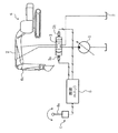
図1は本発明を建設機械の代表例である油圧ショベルの油圧回路制御装置に適用した場合の一実施形態である。ただし、図1では説明の簡略化のため、油圧ショベルのアームを駆動する油圧シリンダに関連する部分的な油圧回路制御装置を示す。
【0035】
図1において、本実施形態の油圧回路制御装置は、油圧ポンプ1と、油圧シリンダ等のアクチュエータ2と、油圧ポンプ1の吐出した圧油の油圧シリンダヘの流入方向、流量を制御する流量制御弁3と、流量制御弁3を駆動する比例電磁弁3a,3bと、操作レバー4aを有し、流量制御弁3の流量を指示する電気的な操作信号を出力する操作レバー装置4と、操作レバー装置4の操作信号に従い比例電磁弁3a,3bへ駆動信号を出力し流量制御弁3を駆動する制御ユニット5とから構成されている。図1では、アクチュエータ2は油圧ショベル6の作業装置中、アーム6aを駆動する油圧シリンダであるとして示しているが、他の作業装置を駆動するアクチュエータであってもよい。
【0036】
図2に制御ユニット5の構成を示す。制御ユニット5は、制御ユニット5全体の制御手順を指示するプログラムを記憶するROMメモリ54、ROMメモリ54に記憶されたプログラムに従い制御ユニット全体を制御するCPU53、CPU53の指示に従い操作レバー装置4の出力する信号を切り換えて入力するマルチプレクサ(MPX)51、マルチプレクサ51に入力された信号をデジタル信号に変換するA/D変換器52、制御演算途中の数値等を一時的に記憶するRAMメモリ55、CPU53からのデジタル値である指令値をアナログ信号に変換して出力するD/A変換器56、D/A変換器56の出力する信号を増幅し、比例電磁弁3a,3bの駆動信号を出力する増幅器57a,57bにより構成されている。
【0037】
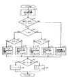
図3に、制御ユニット5のROM54に記憶されているCPU53の制御手順(プログラム)をフローチャートで示す。以下、図3のフローチャートに従い制御手順を説明する。
【0038】
図3において、まずブロック100では、A/D変換器52を介して操作レバー装置4の操作信号(以下、適宜レバー信号という)θを読み込み、RAM55に一時的に記憶する。次にブロック200では、読み込んだレバー信号θをレバー指令値Xへ変換する。次に、ブロック300において、現在出力済みの指令値である前回演算したバルブ指令値Y-1を用い、このバルブ指令値Y-1が中立域の両側の境界値±αの範囲内(以下、適宜「中立域(±α)」という)にあるか、つまり−α<Y−1<αかを判定する。ブロック300で前回演算したバルブ指令値Y-1が中立域にあると判定されるとブロック400へ行く。
【0039】
ここで、レバー指令値X及びバルブ指令値Y,Y-1について説明する。レバー指令値X及びバルブ指令値Y,Y-1はそれぞれ流量制御弁3のスプール位置の指令値であり、レバー指令値Xは演算処理を行う前の操作レバー装置4の現在の操作指令値であり、バルブ指令値Yはこれから述べる演算処理を行った後の指令値であり、実際のスプール位置はこのバルブ指令値Yにより制御される。また、前回演算したバルブ指令値Y-1は図3に示したフローチャートの一周期前の演算処理で演算されたバルブ指令値であり、現在はこのバルブ指令値Y-1相当の駆動信号が出力された直後であり、スプール位置はこのバルブ指令値Y-1により制御されている。
【0040】
バルブ指令値Yと流量制御弁3を流れる圧油流量qの関係の一例を図4に示す。図4に示すようにバルブ指令値Yの中立域(±α)内では流量制御弁3の流量qは0である。中立域を越えるとバルブ指令値Yの絶対値の増加に従って流量qも増加する。この図4のバルブ指令値Y−流量qの関係は一般的なものを示したものであり、対象とするアクチュエータ毎に最適な関係がある。また、操作方向によって異なる特性を持たせることもある。
【0041】
ブロック400の詳細を図5に示す。ブロック400では先のブロック300(図3参照)で前回演算したバルブ指令値Y-1(現在の動作指令値)が中立域にあると判定されているので、中立域におけるバルブ指令値Yの演算を行う。
【0042】
図5において、まずブロック410においてレバー指令値X(現在のレバー操作指令値)も中立域(±α)にあるか、つまり−α≦X≦αかを判定する。ここで、判定がYesの場合は、バルブ指令値Y-1(現在の動作指令値)とレバー指令値X(現在のレバー操作指令値)が共に中立域(±α)にある場合であり、判定がNoの場合は、バルブ指令値Y-1は中立域にあるが、レバー指令値Xは中立域を通り過ぎている場合である。
【0043】
ブロック410でレバー指令値Xが中立域(±α)にあると判定されると、ブロック430へ行く。ブロック430では、バルブ指令値Yをレバー指令値Xの値とする。つまり、バルブ指令値Y-1(現在の動作指令値)とレバー指令値X(現在のレバー操作指令値)が共に中立域(±α)にある場合はバルブ指令値Yをそのままレバー指令値Xの値とする。
【0044】
ブロック410でレバー指令値Xが中立域(±α)を越えたと判定されるとブロック420へ行く。ブロック420では、レバー指令値Xの符号、つまり操作レバー4aが操作されている方向を判定する。レバー指令値Xが0以上の場合ブロック450へ行きバルブ指令値Y=αとする。ブロック420でレバー指令値Xが(−)側であると判断された場合、ブロック440へ行く。ブロック440ではバルブ指令値Y=−αとする。つまり、バルブ指令値Y-1(現在の動作指令値)は中立域にあるが、レバー指令値X(現在のレバー操作指令値)が中立域を通り過ぎている場合は、レバー指令値Xではなく、中立域の境界値α又は−αをバルブ指令値Yの値とする。以上でブロック400を終了してブロック700へ処理を移す。
【0045】
一方、図3において、ブロック300で前回演算したバルブ指令値Y-1(現在の動作指令値)が中立域を越えていた、つまり−α<Y−1<αではないと判断された場合は、ブロック500へ処理を移す。ブロック500では駆動域におけるバルブ指令値Yの演算を行う。ブロック500の詳細を6図に示す。
【0046】
図6において、ブロック500内ではまずブロック510において、レバー指令値X(現在のレバー操作指令値)の前回演算したバルブ指令値Y-1(現在の動作指令値)に対する差分、即ちレバー指令値Xの変化速度ΔXを演算する(ΔX=X−Y-1)。この場合、図3に示した演算処理の1周期の実行時間をΔtとすると、実際のレバー指令値Xの変化速度はΔX/Δtとなる。しかし、Δtはほぼ一定の値であり、比較する最大設定速度ΔY(後述)も同一の周期内での変化速度として用いる方が便利であるので、変化速度はΔXのまま用いる。
【0047】
次にブロック520〜523において、油圧ショベルの操作状態が(1)加速、(2)減速・停止、(3)逆レバーのいずれの状態であるか判定する。まず、ブロック520では、レバー指令値Xと前回演算したバルブ指令値Y-1の比較で符号が一致し(sign(X)=sign(Y-1))、かつレバー指令値Xの絶対値が前回演算したバルブ指令値Y-1の絶対値より大きいことで加速状態であることを判定する。加速状態であると判定されると処理はブロック530へ移る。ブロック530では加速時最大設定速度ΔYを演算する。ここで、ΔYはレバー指令値Xの関数であり、演算方法は、例えば制御ユニット5内のROMメモリ54に図7(a)で示す関数(ΔY=fmax1(X))をテーブル化して記憶しておき、レバー指令値Xの値を参照して該当するΔYを読み出す。また、関数式を記憶しておき、レバー指令値Xを代入して演算する方法等、他の方法によってもよい。このときのレバー指令値Xと最大設定速度ΔYの関係は、図7(a)に示すように、レバー指令値Xの絶対値、つまりレバー操作量が大きくなるに従い最大設定速度ΔYの絶対値が大きくなる関係が操作感覚上好ましい。ただし、この関係は図7(b)の様に|X|が大きくなると徐々に|ΔY|が段階を追って大きくなる関係でも良い。
【0048】
ブロック520で加速状態ではないと判定されると、処理はブロック521へ移る。ブロック521では現状のアクチュエータの動作方向を前回演算したバルブ指令値Y-1の符号(現在の動作指令値)により判定する。前回演算したバルブ指令値Y-1が(+)である(Y-1≧0)と判定されると処理はブロック523へ移る。ブロック523では操作レバー4aの操作方向をレバー指令値Xが中立域より(+)側にあるかどうかで判定する(X≧−α)。レバー指令値Xが(+)側であると判定されると処理はブロック531へ移る。ブロック531では減速・停止時の最大設定速度ΔYを演算する。ここで、ΔYはレバー指令値Xの関数であり、演算方法は、先の関数fmax1と同様に、例えば制御ユニット5内のROMメモリ54に図8で示す関数(ΔY=fmax21(X))をテーブル化して記憶しておき、レバー指令値Xの値を参照して該当するΔYを読み出す。この場合も、関数式を記憶しておき、レバー指令値Xを代入して演算する方法等、他の方法によってもよい。このときのレバー指令値Xと最大設定速度ΔYの関係は、図8に示すように、レバー指令値Xの絶対値、つまりレバー操作量が小さくなり、中立域に近付くに従い最大設定速度ΔYの絶対値が大きくなる関係が操作感覚上好ましい。ただし、この関係も|X|が小さくなるとΔYが段階的に大きくなる関係でも良い。また、このときの最大設定速度の最小値ΔYmin2は、停止時に素早く停止できるようにするために、加速時の最大設定速度の最小値ΔYmin1に対し、ΔYmim2<ΔYmin1とするのが好ましい。
【0049】
ブロック523でレバー指令値Xが(−)側(X<−α)であると判定された場合、つまり逆レバー状態であると判定された場合、処理はブロック532へ移る。ブロック532では逆レバー時の最大設定速度ΔYを演算する。ここで、ΔYはレバー指令値Xの関数であり、演算方法は、先の関数fmax1と同様に、例えば制御ユニット5内のROMメモリ54に図9で示す関数(ΔY=fmax31(X))をテーブル化して記憶しておき、レバー指令値Xの値を参照して該当するΔYを読み出す。関数式を記憶しておき、レバー指令値Xを代入して演算する方法等、他の方法によってもよい。このときのレバー指令値Xと最大設定速度ΔYの関係は図9に示すようにレバー指令値Xの値に係わらず一定の大きな最大設定速度ΔYとなる関係が操作感覚上好ましい。ただし、この関係もXの値に従いΔYが徐々に、あるいは段階的に変化する関係でも良い。また、このときの最大設定速度の最小値ΔYmin3は、逆レバー操作で応答良く動作方向を反転できるようにするため、減速・停止時の最大設定速度の最小値ΔYmin2に対し、ΔYmim3<ΔYmin2とするのが好ましい。
【0050】
先のブロック521で前回演算したバルブ指令値Y-1が(−)であると判定された場合、処理はブロック522へ移る。ブロック522では、操作レバー4aの操作方向をレバー指令値Xが中立域より(−)側かどうかで判定する(X≦α)。レバー指令値Xが(−)側であると判定されると処理はブロック533へ移る。ブロック533では減速・停止時の最大設定速度ΔYを演算する。ここで、ΔYは図8に示す関数(ΔY=fmax22(X))にレバー指令値Xの値を代入して演算する。このときのレバー指令値Xと最大設定速度ΔYの関係は先にfmax21と同様に、図8に示すようにレバー指令値Xの絶対値、つまりレバー操作量が小さくなり、中立域に近付くに従い最大設定速度ΔYの絶対値が大きくなる関係が操作感覚上好ましい。ただし、この関係はfmax21の符号を逆にした関数である必要は無く、操作感覚上最適な関係で良い。また、この関数はテーブル化、あるいは演算式による方法のどちらでも良く、|X|とΔYの関係が段階的なもので良いことは先のΔY=fmax21(X)の関数と同様である。また、このときの最大設定速度の最大値ΔYmax2は、停止時に素早く停止できるようにするために、加速時の最大設定速度の最大値ΔYmax1に対し、ΔYmax2>ΔYmax1とするのが好ましい。
【0051】
ブロック522でレバー指令値Xが(+)側(X>α)であると判定された場合、つまり逆レバー状態であると判定された場合、処理はブロック534へ移る。ブロック534では逆レバー時の最大設定速度ΔYを演算する。ここで、ΔYはレバー指令値Xの関数であり、図9に示す関数(ΔY=fmax32(X))にレバー指令値Xの値を代入して演算する。このときのΔY=fmax32(X)の関係は図9に示すようにレバー指令値Xの値に係わらず一定の大きな最大設定速度ΔYとなる関係が操作感覚上好ましい。ただし、この関数は先のfmax31の符号を逆にした関数である必要は無く、操作感覚上最適なもので良い。また、Xの値に従いΔYが徐々に、あるいは段階的に変化する関係でも良い。また、演算方法はテーブル化、演算式のどちらの方法を用いても良いことは先のfmax31と同様である。また、このときの最大設定速度の最大値ΔYmax3は、逆レバー操作で応答良く動作方向を反転できるようにするため、減速・停止時の最大設定速度の最大値ΔYmax2に対し、ΔYmax3>ΔYmax2とするのが好ましい。
【0052】
以上のようにブロック520〜534において操作状況に応じた最大設定速度ΔYを演算すると、処理はブロック540へ移る。
【0053】
ブロック540〜542では先に求めたレバー指令値Xの変化速度ΔXあるいは最大設定速度ΔYを用いてバルブ指令値Yを演算する。まず、ブロック540においてレバー指令値変化速度ΔXと最大設定速度ΔYを比較する。ここで、|ΔY|≧|ΔX|の場合、レバー操作は急峻ではないと判断し、ブロック541へ処理を移す。そして、ブロック541においてバルブ指令値Y=レバー指令値Xとする。また、ブロック540で|ΔY|<|ΔX|と判断した場合、レバーが急操作されたと判断し、バルブ指令値Yの急な変化を防ぐためにブロック542においてY=Y-1+ΔYの演算でバルブ指令値を求める。以上でブロック500を終了してブロック700へ処理を移す。
【0054】
図3へ戻って、ブロック700では次周期の演算のために前回演算したバルブ指令値Y-1をブロック400又は500で演算した今回のバルブ指令値Yに置き換える(Y-1=Y)。
【0055】
次に、ブロック800においてバルブ指令値Yを電磁比例弁3a,3bのバルブ駆動信号へ変換して出力し、流量制御弁3を制御する。
【0056】
次に、図3〜9で説明した制御手順に基づく動作の一例を図10〜図12のタイムチャートで説明する。図10〜図12の時間軸にその時点で機能する図5及び図6のフローチャートにおけるブロック番号を付記している。
【0057】
まず、図10(a),(b)に操作レバー4aを中立状態から(+)側へ操作した場合のタイムチャートを示す。図中、実線が操作レバー4aの信号(レバー指令値X)であり、一点鎮線が本制御演算によるバルブ指令値Yを示している。操作レバー4aが時刻t0からスタートして時刻t2で最大まで操作されると、レバー指令値Xが中立域にあり(−α≦X≦α)、バルブ指令値Y-1が中立域にある(−α<Y -1<α)t0〜t1間は、先のブロック400「中立不感帯域バルブ指令値演算処理」のブロック430の処理によりバルブ指令値Y=レバー指令値Xの状態が保たれる。レバー指令値Xが中立域を超えると(X>α)、バルブ指令値YはY=αと置かれ、直ちに図3に示したブロック300「中立不感帯判定−α<Y -1 <α」の判断が否定され、その時刻t1からはブロック500「駆動域バルブ指令値演算処理」が実行される。この時、ブロック500中のブロック520の条件(sign(x)=sign(Y-1))かつ(|X|≧|Y-1|)が満たされるので、ブロック530「加速時最大設定速度演算」が実行される。そこで、時刻t1以降はレバー指令値変化速度ΔXと最大設定速度ΔYが比較されてどちらか絶対値の小さな方の値に従ってバルブ指令値Yが増加していく。
【0058】
図10(a)に急に操作レバー4aを操作した場合、つまり|ΔY|<|ΔX|の場合を示す。この時は、ブロック500中のブロック542の処理がなされ、一点鎖線に示すように時刻t1以降、ΔYの値に従ってバルブ指令値Yが増加し、このことにより、操作レバー4aを急に操作してもバルブ指令値の変化速度はΔY以下に押さえられ、ショックが無く、遅れを感じない速さでアクチュエータ2を起動(加速)することができる。また、ΔYはレバー指令値Xの関数であるので、レバー指令値X(操作信号の値)に応じた最適の最大変化速度が設定され、操作レバー4aの操作量に応じた適切な加速感が得られる。
【0059】
図10(b)には緩やかに操作レバー4aを操作した場合を示す。この時はレバー操作によるレバー信号の変化速度ΔXが最大設定速度ΔYより小さい(|ΔY|≧|ΔX|)ので、ブロック500中のブロック541の処理がなされ、図10(b)中に示すようにバルブ指令値Yはレバー指令値Xに一致する。従って、オペレータの所望の加速感でアクチュエータ2を起動(加速)することができる。
【0060】
図11に操作レバー4aを最大操作位置から中立位置へ急に戻し、アクチュエータを停止させようとした場合を示す。時刻t0〜t1の間に操作レバー4aを急に戻すと、|X|<|Y-1|となり、ブロック500中のブロック520の条件(sign(x)=sign(Y-1))かつ(|X|≧|Y-1|)が否定され、制御ブロック500中のブロック531の減速・停止時状態であると判定される。従って、図8に示した関数ΔY=fmax21(X)により設定最大速度が演算される。また、この時は、レバー指令値Xは時刻t0からt1で最大値から0へ戻されるので、|ΔY|<|ΔX|の状態であると判断されると、ブロック500中のブロック542の処理がなされ、一点鎖線に示すようにΔYの値に従ってバルブ指令値Yは減少する。時刻t1以降もその状態が継続し、バルブ指令値Yは時刻t2で中立域の(+)側の境界値(Y=α)まで戻る。Y=αになると、直ちに先に図3に示したブロック300「中立不感帯判定−α<Y-1<α」の判断が肯定され、ブロック400で示した「中立不感帯域バルブ指令値演算処理」に移行する。そして、この時はX=0であるので図5のブロック430の処理が行われ、すぐにY=X=0の状態になる。このように、停止時には急に操作レバー4aが戻されても機体にショックを与えず、かつ緩慢な停止にならない設定最大速度ΔYの関係(Y=fmax21(X))により機体は停止する。
【0061】
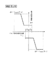
次に、図12に操作レバー4aを時刻t0からt2で(+)側最大値から(−)側最小値(絶対値は最大)へ急に操作した場合(以後、逆レバー状態と呼ぶ)を示す。図中、時刻t0からt1′の間は図6に示したブロック500中のブロック531の減速・停止時最大設定速度演算が行われ、図8の関数ΔY=fmax21(X)に従った最大設定速度ΔYによりバルブ指令値Yの変化が規制され、ブロック500中のブロック542の処理によりそのΔYの値に従ってバルブ指令値Yは減少する。時刻t1′においてレバー指令値Xが中立域の(−)側の境界値−αに到達すると(X=−α)、その後はブロック532の逆レバー時最大設定速度演算が行われ、図9の関数ΔY=fmax31(X)に従った最大設定速度ΔYによりバルブ指令値Yの変化が規制され、同様にそのΔYの値に従ってバルブ指令値Yは減少する。
【0062】
時刻t3においてバルブ指令値Yが中立域の(+)側の境界値αに至ると(Y=α)、直ちに図3に示したブロック300「中立不感帯判定−α<Y-1<α」の判断が肯定され、ブロック400で示した「中立不感帯域バルブ指令値演算処理」に移行する。この時、既にレバー指令値Xは(−)側最小値まで到達しているので図5中のブロック440の処理が行われ、バルブ指令値Y=−αとなる。その後、時刻t3からt4の間は図6中のブロック530「加速時最大設定速度演算」が行われ、図7(a)の関数ΔY=fmax1(X)中のレバー指令値Xが(−)側での設定最大速度ΔYに従ってバルブ指令値Yが演算される。
【0063】
ここで逆レバー状態とは、例えばバケットの泥落とし、ブームを使用した土羽打ち作業あるいは危険回避等の様に作業装置の動作方向を急に変えたいときの操作であり、作業装置の動作方向を変えるまでは早い応答が望まれる。操作方向と作業装置の動作方向が一致した後は通常の作業と同じく緩慢でなくショックの無い特性が望まれる。
【0064】
本実施形態によれば、図12に示したように時刻t0からt1′までは図8の減速・停止時の関数ΔY=fmax21(X)に従った最大設定速度ΔYによりバルブ指令値Yの変化が規制されるが、時刻t1′からt3までは図9の逆レバー時の関数ΔY=fmax31(X)に従った最大設定速度ΔYによりバルブ指令値Yの変化が規制され、このときの最大設定速度ΔYの最小値ΔYmin3は減速・停止時の最大設定速度の最小値ΔYmin2に対し、ΔYmim3<ΔYmin2であり、高応答で作業装置の動作方向を反転できる。また、時刻t3でバルブ指令値Yが中立域の(+)側の境界値αに至ると(Y=α)、直ちに図5中のブロック440の処理でバルブ指令値Y=−αとなり、バルブ指令値Yは中立域(±α)で瞬時に変化し、かつ時刻t3以降は図7(a)の加速時の関数ΔY=fmax1(X)の設定最大速度ΔYに従ってバルブ指令値Yが演算される。このため、操作方向と作業装置の動作方向が一致する中立付近での息付きを感じない操作が可能となり、更に操作方向と作業装置の動作方向が一致した後は通常の作業と同じく緩慢でなくショックの無い特性が得られる。
【0065】
図13に制御ユニット5の制御演算を機能ブロック図で示す。図中、ブロック900の「レバー指令値演算」は図3中のブロック100,200に相当する。一点鎖線のブロック910は図3中のブロック300に相当し、ブロック910aの「中立不感帯域判定」と処理切換スイッチ810bとで構成されている。ブロック911の「中立不感帯域バルブ指令値演算」は図3中のブロック400に相当する。一点鎖線のブロック912は図3中のブロック500に相当し、その中のブロック920の「レバー指令値変化速度演算」は図6中のブロック510に相当し、ブロック921の「操作状態判定」は図6中のブロック520〜523に相当し、ブロック922の「バルブ指令最大設定速度演算」は図6中のブロック530〜534に相当し、ブロック923の「バルブ指令変化速度判定」は図6中のブロック540に相当し、ブロック924の「駆動域バルブ指令値演算」は図6中のブロック541,542に相当する。更に、ブロック940の「バルブ指令値記憶」は図3中のブロック700に相当し、ブロック950は図3中のブロック800に相当する。
【0066】
また、図13中のブロック921は、操作信号に基づき建設機械の操作状況を判定する第1判定手段に相当し、ブロック922〜924が、建設機械の操作状況毎にバルブ指令値の最適の最大変化速度が予め設定されており、第1判定手段の判定結果に基づき、そのときの建設機械の操作状況に対応する最適の最大変化速度を決定し、バルブ指令値の変化速度が最適の最大変化速度以下となるように規制する第1演算手段を構成する。
【0067】
更に、図13中のブロック910(ブロック910a及び処理切換スイッチ910b)は、バルブ指令値が中立域内にあるかどうかを判定する第2判定手段を構成し、ブロック911は、バルブ指令値が流量制御弁の中立域内にあるときは前記最大変化速度によるバルブ指令値の変化速度を規制する演算を行わず、操作信号に従ったバルブ指令値を演算する第2演算手段とを構成する。
【0068】
以上のように本実施形態によれば、電気的な操作信号で流量制御弁3を制御しアクチュエータ2の動作を制御するもので、加速時、減速・停止時、逆レバー操作時のいずれの操作状況にあっても、最適の最大変化速度で流量制御弁3を制御でき、
(a)加減速時は、操作レバー4aを急操作してもショックが少なく、遅れを感じず;
(b)緩やかな加減速操作時はオペレータの意志通りに動き;
(c)停止操作時には操作レバー4aを急操作してもショックが少なく、遅れを感じない動作となり;かつ;
(d)急な逆レバー操作時にはアクチュエータ2の素早い反転動作が可能となり、かつ動作速度の反転前後においてショック少なく、遅れを感じず、同時に中立付近での息付きを感じない操作が可能となる。このため、作業能率及び安全性が向上する効果が得られる。
【0069】
また、操作レバー4aの位置(操作信号の値)で最大変化速度が可変となっているので、操作次第では流量制御弁3の最大変化速度を所望の形で制御でき、操作レバー4aの操作量に応じた適切な加速感、減速感が得られる。例えば、操作レバー4aの戻し時に操作信号が0になる手前(図8のΔYmin2になる前のレバー位置)で少し止めておくことで、最大変化速度を少し遅くし、最後の所で操作レバー4aを0に戻すことにより、よりショックの少ない操作が可能となる。
【0070】
図14に本発明の第2の実施形態を示す。本実施形態は先の第1の実施形態の図3中のブロック500を図14に示すブロック500Bに置き換えたものである。図中、図6のブロック500の詳細に示した各サブブロックと同じ機能を果たすものには同じ符号を付している。
【0071】
図14の中でブロック531B,533Bが先の図6のブロック531,533と異なる機能を有している。ブロック531B,533Bは操作状態が減速または停止状態であるときに実行される「減速・停止時最大設定速度演算」のブロックである。ここで、最大設定速度ΔYは前回出力したバルブ指令値Y-1の関数ΔY=fmax23(Y-1),ΔY=fmax24(Y-1)で求められる。
【0072】
関数ΔY=fmax23(Y-1),ΔY=fmax24(Y-1)を図15に示す。ここではバルブ指令値の前回値Y-1が中立に戻る程、最大設定速度の絶対値|ΔY|が小さな値となるように設定している。
【0073】
この関数を用いた実際の動作を図16に示す。図16において、時刻t0〜t1にかけて操作レバー4aが急激に戻されると、図15に示したΔY=Fmax23(Y-1)の関数により最大設定速度ΔYが求められる。その結果、図16のt0〜t2に一点鎖線で示すように、バルブ指令値Yは中立域に戻るに従い変化速度が遅くなる。この結果、急な操作をしても作業装置は停止寸前にショックを和らげるように速度が遅くなり、かつ初期速度が大きいので遅れを感じないで停止する。
【0074】
【発明の効果】
本発明によれば、電気的な操作信号で流量制御弁を制御しアクチュエータの動作を制御するもので、操作状況を判定して最適の最大設定速度を演算するので、加速時、減速・停止時、逆レバー操作時のいずれの操作状況にあっても、最適の最大変化速度で流量制御弁を制御でき、
(a)加減速時は、操作レバーを急操作してもショックが少なく、遅れを感じず;
(b)緩やかな加減速操作時はオペレータの意志通りに動き;
(c)停止操作時には操作レバーを急操作してもショックが少なく、遅れを感じない動作となり;かつ;
(d)急な逆レバー操作時にはアクチュエータの素早い反転動作が可能となり、作業能率の向上及び安全性の向上が図れる。
【0075】
また、操作信号の値に応じた最適の最大変化速度が設定されるので、操作レバーの操作量に応じた適切な加速感、減速感が得られる。
【0076】
また、本発明によれば、逆レバー時に動作速度の反転前後においてショック少なく、遅れを感じず、同時に中立付近での息付きを感じない操作が可能となる。
【0077】
更に、本発明によれば、操作信号の値と前回出力したバルブ指令値に応じた最適の最大変化速度を設定するので、操作レバーの操作量に応じた適切な加速感、減速感が得られる。
【図面の簡単な説明】
【図1】本発明の第1の実施形態による建設機械の油圧回路制御装置の全体構成を示す図である。
【図2】図1に示した制御ユニットの構成を示すブロック図である。
【図3】図1に示した制御ユニットでなされる制御演算を示すフローチャートである。
【図4】制御ユニットで演算されるバルブ指令値Yとこのバルブ指令値により制御される流量制御弁を流れる圧油流量qの関係を示す特性図である。
【図5】図3にフローチャートで示した制御演算のうちの「中立不感帯域バルブ指令値演算処理」の詳細を示すフローチャートである。
【図6】図3にフローチャートで示した制御演算のうちの「駆動域バルブ指令値演算処理」の詳細を示すフローチャートである。
【図7】(a)加速時の最大設定遠度を求める関数の特性図であり、(b)は同特性図の他の例である。
【図8】減速・停止時の最大設定遠度を求める関数の特性図である。
【図9】逆レバー時の最大設定遠度を求める関数の特性図である。
【図10】加速時の動作の一例を示すタイムチャートであり、(a)は操作レバーを急に操作した場合であり、(b)は操作レバーを緩やかに操作した場合である。
【図11】減速・停止時の動作の一例を示すタイムチャートである。
【図12】逆レバー時の動作の一例を示すタイムチャートである。
【図13】図3、図5及び図6にフローチャートで示した制御演算を機能ブロックで示す図である。
【図14】本発明の第2の実施形態による建設機械の油圧回路制御装置における図6と同様な「駆動域バルブ指令値演算処理」の詳細を示すフローチャートである。
【図15】第2の実施形態における減速・停止時の最大設定遠度を求める関数の特性図である。
【図16】第2の実施形態における減速・停止時の動作の一例を示すタイムチャートである。
【符号の説明】
1 油圧ポンプ
2 油圧シリンダ
3 流量制御弁
3a,3b 比例電磁弁
4 操作レバー装置
4a 操作レバー
5 制御ユニット
6 作業装置
6a アーム[0001]
BACKGROUND OF THE INVENTION
The present invention is an operation system using a joystick device of a type in which an operation system of a construction machine, in particular, an operation lever device generates an electric operation signal (electric signal) according to an operation amount of the operation lever, The present invention also relates to a hydraulic circuit control device for a construction machine that controls a flow rate control valve with an operation signal to control an operation of an actuator.
[0002]
[Prior art]
In recent construction machines, in particular, machines used for various operations such as hydraulic excavators, operability tends to be emphasized in order to cope with various usages. In other words, the hydraulic excavator must be a machine that can operate the work device according to the will of the operator, from work that places importance on work volume, such as excavation work, to operation that requires fine adjustment, such as leveling work. Therefore, there is a hydraulic circuit control device of a type in which the operation lever device is an electric joystick that generates an electric operation signal according to the operation amount, the operation signal is electrically processed, and the flow control valve is controlled by the signal. It is being used. The following is known as such a control device.
[0003]
(1) Japanese Patent No. 2509311 "Construction machine control method for construction machine"
Hydraulic control valve (operating valve) and pump that are operated via the controller by operating the electric leverVariable deviceIn the construction machine control method for a construction machine equipped with, the ratio of increase / decrease and increase / decrease with the operating time for the increase / decrease of the circuit pressure and the increase / decrease of the pump discharge amount by operating the operation valve is sequentially changed in multiple stages. When a modulation pattern that limits the maximum operating speed of the operation valve (maximum change speed of the operation signal) is set, and the circuit pressure rises and falls at a certain rate with the operating time, the operation valve does not move faster than the modulation pattern And pump variable device, operating valve and pumpVariable deviceModulation control that absorbs the shock that occurs during operation of the pump and further pumpVariable deviceIt is shown to prevent cavitation that occurs during the operation of the. In addition, it is shown that a plurality of modulation patterns of operation valves are prepared, and manual or automatic setting is performed according to a work state by an operator's selection.
[0004]
(2) Japanese Patent Publication No. 7-107279 “Worker control method for construction machines”
In the modulation control of (1) above, when the operation signal of the electric lever moves from the operation position on one side to the reverse side beyond the dead zone, which is the neutral position, as a series of operations, the previous modulation pattern is released. In addition, it is shown that the modulation pattern on the reverse direction side is applied to match the operation feeling of the reverse lever operation with the work implement operation.
[0005]
(3) Japanese Patent Laid-Open No. 10-37247 “Operation Control Device and Operation Control Method”
In a hydraulic circuit control device that controls the drive of a work machine of a construction machine via a flow control valve, the maximum change rate of the operation signal of the flow control valve is restricted to a set value or less, and the set value is operated by an operation lever. It is shown that the control is changed according to the amount.
[0006]
In addition, the hydraulic circuit control device regulates the maximum operating speed of the variable pump capacity mechanism by controlling the actuator speed by controlling the discharge amount of the hydraulic pump with the operation signal instead of controlling the flow control valve with the operation signal. Are known as follows.
[0007]
(4) Japanese Patent Publication No. 62-13542 "Hydraulic circuit control device"
Set the operating speed of the variable pump volume mechanism in the hydraulic circuit controller of the closed circuit system that controls the actuator speed to the speed indicated by the operating device by controlling the hydraulic pump discharge amount (position of the variable pump volume mechanism) It is shown that the acceleration / deceleration of the actuator is controlled by changing the set maximum speed according to the operation amount of the operation lever when the speed is restricted to the maximum speed or less.
[0008]
(5) Japanese Patent Publication No. 62-39295 “Control system for hydraulic circuit device”
In the control device of (4) above, it is detected that the operating device (operating lever) is instructed to stop or drive in the reverse direction, and indicates that the set maximum speed larger than the set maximum speed at the time of acceleration is set. Has been.
[0009]
[Problems to be solved by the invention]
However, the above prior art has the following problems.
[0010]
First, the first problem is that the set value that limits the maximum operating speed (maximum change speed of the operation signal) of the operation valve (flow control valve) is the value when accelerating, decelerating / stopping, or operating the reverse lever. It is not set corresponding to each, and it is not always possible to control the operation valve at the optimum maximum change speed according to the operation state of the construction machine.
[0011]
The second problem is that the dead zone near the neutral of the flow control valve at the time of reverse lever operation is not appropriate, or no treatment has been done, and a shock occurs near the neutral at the time of sudden reverse lever operation. The actuator does not move and you feel a breath.
[0012]
The third problem is that the maximum change speed of the operation valve is limited to a regular modulation pattern regardless of the operation amount of the operation lever, so that an appropriate acceleration feeling and deceleration feeling according to the operation amount cannot be obtained. is there.
[0013]
That is, in Japanese Patent No. 2509311 and Japanese Patent Publication No. 7-107279, the maximum operating speed of the operation valve at the time of acceleration and deceleration / stop is set as a modulation pattern, and the modulation at the time of deceleration / stop is performed when the reverse lever is operated. The maximum operating speed of the operation valve is limited by the pattern. However, the reverse lever operation is an operation for suddenly changing the operation direction of the work device, for example, for removing mud from a bucket, working with a boom using a boom, or avoiding danger. A quick response is desired until changed. For this reason, if the maximum operating speed of the operating valve is limited by the modulation pattern at the time of deceleration / stop, it cannot be said that the optimum maximum changing speed for the reverse lever operation, and the operating direction of the working device cannot be changed with good response (first response). Problem).
[0014]
In Japanese Patent Publication No. 7-107279, in order to improve the responsiveness in the reverse lever operation in Japanese Patent No. 2509311, the modulation control up to that point is turned off at the moment when the operation signal indicates the reverse direction, Since the modulation control of the actuator is started, the actuator becomes uncontrolled at the moment when the operation direction changes considering the operation delay of the actuator with respect to the operation signal, and it is possible to generate a large shock until the operation direction is switched (Second problem).
[0015]
Further, in Japanese Patent No. 2509311 and Japanese Patent Publication No. 7-107279, the modulation pattern is fixed, and the maximum operating speed of the operation valve is always limited to the modulation pattern regardless of the operation amount of the operation lever. It is not possible to obtain an appropriate acceleration feeling and deceleration feeling according to the above (third problem). For example, when returning the operation lever, if the operation valve speed is faster than the modulation pattern, the maximum change speed of the operation valve is determined by the regular modulation pattern regardless of how the operation lever is returned. It cannot be adjusted.
[0016]
In Japanese Patent Laid-Open No. 10-37247, the maximum operating speed of the operating valve is not set in accordance with the operation status of the construction machine, and the operating valve cannot be controlled at the optimum maximum change speed in accordance with the operating status (first And a feeling of acceleration and deceleration appropriate for the operation amount cannot be obtained (third problem). In addition, no consideration is given to the reverse lever operation (second problem).
[0017]
Japanese Patent Publication No. 62-13542 and Japanese Patent Publication No. 62-39295 are for controlling the pump discharge amount by controlling the position of the variable pump volume mechanism according to the instruction of the operation lever, and controlling the speed of the actuator. The drive of the construction machine working machine is not controlled via the flow control valve. In the system disclosed in Japanese Examined Patent Publication No. 62-39295, a plurality of operation signal maximum change speeds are set as a function of the operation signal. However, since the object to be controlled by the operation lever is the variable pump volume mechanism, no consideration is given to the dead zone near the neutrality of the flow control valve. For this reason, when the configuration is applied to a hydraulic circuit control device that controls the speed of an actuator via a flow control valve, the maximum change rate of the operation signal is regulated as it is when the flow control valve is in the dead zone near the neutral position. In the meantime, an area where the actuator does not move is formed, and a feeling of breathing is felt (second problem).
[0018]
The first object of the present invention is to control the flow control valve with an electric operation signal to control the operation of the actuator. In any operation state during acceleration, deceleration / stop, or reverse lever operation. Can control the flow control valve at the optimum maximum change speed,
(A) When accelerating / decelerating, even if the operating lever is operated suddenly, there is little shock and no delay is felt;
(B) When accelerating / decelerating slowly, move according to the operator's will;
(C) During stop operation, even if the operating lever is operated suddenly, there is little shock and the operation does not feel a delay; and;
(D) To provide a hydraulic circuit control device for a construction machine that allows a quick reverse operation of an actuator during a sudden reverse lever operation.
[0019]
In addition to the above, the second object of the present invention is to appropriately handle the dead zone near the neutrality of the flow control valve during reverse lever operation. It is an object of the present invention to provide a hydraulic circuit control device for a construction machine that does not feel a breath near neutral.
[0020]
A third object of the present invention is to provide a hydraulic circuit control device for a construction machine that can provide an appropriate feeling of acceleration and deceleration according to the operation amount of an operation lever.
[0021]
[Means for Solving the Problems]
(1) The firstAnd secondIn order to achieve the above object, the present invention provides a hydraulic actuator that drives a working device, a hydraulic pump that is driven by a prime mover to generate pressure oil, and a flow rate of pressure oil that is provided between the hydraulic actuator and the hydraulic pump. A flow control valve to be controlled, and an electrical operation signal indicating the flow rate of the flow control valveAn operation signal corresponding to the operation amount of the operation leverOperations that generateLever deviceAnd the operation signalBased on valve command valueAnd thatValve command valueIn the hydraulic circuit control device for a construction machine that controls the flow rate control valve by:
First determination means for determining an operation state of the construction machine based on the operation signal;
For each operation status of construction machineryValve command valueIs determined in advance, and based on the determination result of the first determination means, the optimal maximum change speed corresponding to the operation status of the construction machine at that time is determined,Restricted so that the change rate of the valve command value is less than the optimum maximum change rate.First computing means toA second determination means for determining whether or not the valve command value is in a neutral range, and an operation for regulating a change speed of the valve command value by the optimum maximum change speed when the valve command value is in the neutral range. Second calculating means for calculating a valve command value according to the operation signal without performingShall be provided.
[0022]
In this way, the operation status of the construction machine is determined by the first determination means, and the optimum maximum change speed corresponding to the operation status of the construction machine at that time is determined based on the determination result by the first calculation means,Regulates the change rate of the valve command value to be less than or equal to its optimum maximum change rateBy,The flow control valve can be controlled at the optimum maximum change speed regardless of the speed, deceleration / stop, or reverse lever operation. (A) During acceleration / deceleration, operate the operation lever suddenly. There is little shock and feels no delay. (B) When the acceleration / deceleration operation is performed smoothly, it moves according to the operator's will. (C) Even when the operation lever is suddenly operated during stop operation, there is little shock and no delay is felt. In addition, (d) the actuator can be quickly reversed during a sudden reverse lever operation, and the work efficiency and safety are improved.
[0024]
Further, the second determining means determines whether or not the valve command value is in the neutral range, and the second calculating means determines the change rate of the valve command value by the optimum maximum change speed when the valve command value is in the neutral range. By calculating the valve command value according to the operation signal without performing the calculation to regulate,The dead zone near the neutrality of the flow control valve during reverse lever operation is properly processed, there is little shock during sudden reverse lever operation, and there is no delay, and at the same time, you can feel no breath near neutral, Operability at the time of reverse lever is greatly improved.
[0025]
(2)In order to achieve the first object, the present invention includes a hydraulic actuator that drives a working device, a hydraulic pump that is driven by a prime mover to generate pressure oil, a pressure provided between the hydraulic actuator and the hydraulic pump. A flow control valve for controlling the flow rate of oil, and an operation lever device for generating an operation signal corresponding to an operation amount of the operation lever, which is an electrical operation signal for instructing a flow rate of the flow control valve, In a hydraulic circuit control device for a construction machine that calculates a valve command value based on an operation signal and controls the flow control valve based on the valve command value, a first determination unit that determines an operation status of the construction machine based on the operation signal And an optimum maximum change rate of the valve command value is preset for each operation state of the construction machine, and the construction machine at that time is based on the determination result of the first determination means. Of determining the maximum rate of change of the optimum corresponding to the operation conditions, the rate of change of the valve command value and a first arithmetic means for regulating such that less than the maximum rate of change of the optimum,The first determining means determines whether the operation status of the construction machine is in acceleration, deceleration / stop, or reverse lever from the state of the operation signal, and the first calculation means is acceleration, deceleration / stop, reverse Preset for each lever operation situationValve command valueThe optimum maximum change speed corresponding to the operation state of the construction machine at that time is determined from the optimum maximum change speed ofShall.
[0026]
As a result, as described in (1) above, the flow rate control valve can be controlled at the optimum maximum change speed regardless of the operating state during acceleration, deceleration / stop, and reverse lever operation.
[0027]
(3In addition, the above (1) or (2), Preferably, the first determination means outputs the operation signal and the previous time.Valve command valueThe operational state of the construction machine is determined from the above.
[0028]
Thus, the first determination means can determine the operation status of the construction machine including acceleration, deceleration / stop, and reverse lever operation without using a special sensor signal.
[0029]
(4Further, in order to achieve the third object, the present invention provides the above (1).~ (3)In any of the above,Valve command valueThe optimum maximum change speed is preset for each operation situation of the construction machine as a function of the operation signal, and the first calculation means has an operation signal corresponding to the operation situation determined by the first determination means. The optimum maximum change speed is calculated from the function and the operation signal at that time.
[0030]
As a result, depending on the value of the operation signalValve command valueThe optimum maximum change speed is set, and an appropriate acceleration feeling and deceleration feeling according to the operation amount of the operation lever can be obtained.
[0031]
(5Also, the above (1)~ (3)In any of the above, preferablyValve command valueThe optimum maximum change speed of the operation signal or the previous outputValve command valueIs set in advance for each operation situation of the construction machine, and the first calculation means outputs an operation signal corresponding to the operation situation determined by the first determination means or a previous output.Valve command valueFunction and operation signal at that time or last outputValve command valueThe optimum maximum change speed is calculated from the above.
[0032]
As a result, the value of the operation signal and the last outputValve command valueAccording toValve command valueThe optimum maximum change speed is set, and an appropriate acceleration feeling and deceleration feeling according to the operation amount of the operation lever can be obtained.
[0033]
DETAILED DESCRIPTION OF THE INVENTION
Hereinafter, embodiments of the present invention will be described with reference to the drawings.
[0034]
FIG. 1 shows an embodiment in which the present invention is applied to a hydraulic circuit control device of a hydraulic excavator which is a typical example of a construction machine. However, in order to simplify the description, FIG. 1 shows a partial hydraulic circuit control device related to a hydraulic cylinder that drives an arm of a hydraulic excavator.
[0035]
In FIG. 1, the hydraulic circuit control device of the present embodiment includes a
[0036]
FIG. 2 shows the configuration of the
[0037]
FIG. 3 is a flowchart showing a control procedure (program) of the CPU 53 stored in the
[0038]
In FIG. 3, first, in
[0039]
Here, the lever command value X and the valve command values Y and Y-1 will be described. The lever command value X and the valve command values Y and Y-1 are the command values of the spool position of the flow control valve 3, respectively. The lever command value X is the current operation command value of the operation lever device 4 before the calculation process. Yes, the valve command value Y is a command value after performing the arithmetic processing described below, and the actual spool position is controlled by this valve command value Y. Further, the previously calculated valve command value Y-1 is a valve command value calculated in the calculation process one cycle before the flowchart shown in FIG. 3, and a drive signal corresponding to the valve command value Y-1 is currently output. Immediately after the operation, the spool position is controlled by the valve command value Y-1.
[0040]
An example of the relationship between the valve command value Y and the pressure oil flow rate q flowing through the flow control valve 3 is shown in FIG. As shown in FIG. 4, the flow rate q of the flow rate control valve 3 is 0 within the neutral range (± α) of the valve command value Y. When the neutral range is exceeded, the flow rate q increases as the absolute value of the valve command value Y increases. The relationship between the valve command value Y and the flow rate q in FIG. 4 shows a general relationship, and there is an optimum relationship for each target actuator. Also, different characteristics may be given depending on the operation direction.
[0041]
Details of
[0042]
In FIG. 5, first, in
[0043]
If it is determined in
[0044]
If it is determined in
[0045]
On the other hand, in FIG. 3, the valve command value Y-1 (current operation command value) previously calculated in
[0046]
In FIG. 6, in
[0047]
Next, in
[0048]
If it is determined at
[0049]
If it is determined in
[0050]
If it is determined in the
[0051]
If it is determined in
[0052]
As described above, when the maximum set speed ΔY corresponding to the operation state is calculated in
[0053]
In blocks 540 to 542, the valve command value Y is calculated using the change speed ΔX or the maximum set speed ΔY of the lever command value X previously obtained. First, in
[0054]
Returning to FIG. 3, in
[0055]
Next, in
[0056]
Next, an example of the operation based on the control procedure described with reference to FIGS. 3 to 9 will be described with reference to time charts of FIGS. The block numbers in the flowcharts of FIGS. 5 and 6 which function at that time are added to the time axis of FIGS.
[0057]
First, FIGS. 10A and 10B show time charts when the
[0058]
FIG. 10A shows a case where the
[0059]
FIG. 10B shows a case where the
[0060]
FIG. 11 shows a case where the
[0061]
Next, FIG. 12 shows a case where the
[0062]
When the valve command value Y reaches the (+) side boundary value α of the neutral region at time t3 (Y = α), immediately after the
[0063]
Here, the reverse lever state is an operation for suddenly changing the operation direction of the work device, such as mud dropping of a bucket, earthing work using a boom or danger avoidance, and the operation direction of the work device. A quick response is desired until the change is made. After the operation direction and the operation direction of the work device coincide with each other, a characteristic that is not slow and shock-free as in normal work is desired.
[0064]
According to the present embodiment, as shown in FIG. 12, from time t0 to t1 ′, the valve command value Y changes with the maximum set speed ΔY according to the function ΔY = fmax21 (X) at the time of deceleration / stop in FIG. However, from time t1 'to t3, the change in the valve command value Y is restricted by the maximum setting speed ΔY according to the function ΔY = fmax31 (X) at the time of the reverse lever in FIG. The minimum value ΔYmin3 of the speed ΔY is ΔYmim3 <ΔYmin2 with respect to the minimum value ΔYmin2 of the maximum set speed at the time of deceleration and stop, and the operation direction of the work device can be reversed with high response. Further, when the valve command value Y reaches the (+) side boundary value α in the neutral region (Y = α) at time t3, the valve command value Y = −α is immediately obtained by the processing of
[0065]
FIG. 13 is a functional block diagram showing the control calculation of the
[0066]
A
[0067]
Furthermore, the block 910 (block 910a and the processing changeover switch 910b) in FIG.Valve command valueConstitutes a second judging means for judging whether or not is in the neutral zone,Valve command valueIs within the neutral range of the flow control valve,Valve command valueThe calculation that regulates the rate of change ofValve command valueAnd second calculating means for calculating.
[0068]
As described above, according to the present embodiment, the operation of the
(A) At the time of acceleration / deceleration, even if the operating
(B) When accelerating / decelerating slowly, move according to the operator's will;
(C) At the time of stop operation, even if the
(D) When the reverse lever is suddenly operated, the
[0069]
Further, since the maximum change speed is variable depending on the position of the
[0070]
FIG. 14 shows a second embodiment of the present invention. In this embodiment, the
[0071]
In FIG. 14, blocks 531B and 533B have different functions from
[0072]
The functions ΔY = fmax23 (Y−1) and ΔY = fmax24 (Y−1) are shown in FIG. Here, the absolute value | ΔY | of the maximum set speed is set to a smaller value as the previous value Y-1 of the valve command value returns to neutral.
[0073]
An actual operation using this function is shown in FIG. In FIG. 16, when the operating
[0074]
【The invention's effect】
According to the present invention, the flow control valve is controlled by an electric operation signal to control the operation of the actuator. The operation state is determined and the optimum maximum set speed is calculated, so at the time of acceleration, deceleration / stop Regardless of the operating condition during reverse lever operation, the flow control valve can be controlled at the optimum maximum change speed,
(A) When accelerating / decelerating, even if the operating lever is operated suddenly, there is little shock and no delay is felt;
(B) When accelerating / decelerating slowly, move according to the operator's will;
(C) During stop operation, even if the operating lever is operated suddenly, there is little shock and the operation does not feel a delay; and;
(D) When the reverse lever is suddenly operated, the actuator can be quickly reversed, and the work efficiency and safety can be improved.
[0075]
In addition, since the optimum maximum change speed according to the value of the operation signal is set, appropriate acceleration feeling and deceleration feeling according to the operation amount of the operation lever can be obtained.
[0076]
Further, according to the present invention, it is possible to perform an operation with little shock before and after the reversal of the operation speed at the time of the reverse lever, without feeling a delay and at the same time feeling no breathing near the neutral position.
[0077]
Furthermore, according to the present invention, the value of the operation signal and the previous outputValve command valueSince the optimum maximum change speed according to the setting is set, it is possible to obtain an appropriate acceleration feeling and deceleration feeling according to the operation amount of the operation lever.
[Brief description of the drawings]
FIG. 1 is a diagram showing an overall configuration of a hydraulic circuit control device for a construction machine according to a first embodiment of the present invention.
FIG. 2 is a block diagram showing a configuration of a control unit shown in FIG.
FIG. 3 is a flowchart showing a control calculation performed by the control unit shown in FIG. 1;
FIG. 4 is a characteristic diagram showing a relationship between a valve command value Y calculated by a control unit and a pressure oil flow rate q flowing through a flow rate control valve controlled by the valve command value.
5 is a flowchart showing details of “neutral dead band valve command value calculation processing” in the control calculation shown in the flowchart in FIG. 3; FIG.
6 is a flowchart showing details of “driving range valve command value calculation processing” in the control calculation shown in the flowchart of FIG. 3;
7A is a characteristic diagram of a function for obtaining a maximum set distance during acceleration, and FIG. 7B is another example of the characteristic diagram.
FIG. 8 is a characteristic diagram of a function for obtaining a maximum set distance during deceleration / stopping.
FIG. 9 is a characteristic diagram of a function for obtaining a maximum set distance at the time of a reverse lever.
FIGS. 10A and 10B are time charts showing an example of an operation during acceleration, where FIG. 10A shows a case where the operation lever is suddenly operated, and FIG. 10B shows a case where the operation lever is operated gently.
FIG. 11 is a time chart showing an example of operation during deceleration / stopping.
FIG. 12 is a time chart showing an example of an operation at the time of a reverse lever.
FIG. 13 is a functional block diagram showing the control calculation shown in the flowcharts of FIGS. 3, 5 and 6;
FIG. 14 is a flowchart showing details of “driving range valve command value calculation processing” similar to FIG. 6 in the hydraulic circuit control device for a construction machine according to the second embodiment of the present invention.
FIG. 15 is a characteristic diagram of a function for obtaining a maximum set distance during deceleration / stop in the second embodiment.
FIG. 16 is a time chart showing an example of an operation at the time of deceleration / stop in the second embodiment.
[Explanation of symbols]
1 Hydraulic pump
2 Hydraulic cylinder
3 Flow control valve
3a, 3b proportional solenoid valve
4 Operation lever device
4a Operation lever
5 Control unit
6 Working device
6a arm
Claims (5)
前記操作信号に基づき建設機械の操作状況を判定する第1判定手段と、
建設機械の操作状況毎に前記バルブ指令値の最適の最大変化速度が予め設定されており、前記第1判定手段の判定結果に基づき、そのときの建設機械の操作状況に対応する最適の最大変化速度を決定し、前記バルブ指令値の変化速度が前記最適の最大変化速度以下となるように規制する第1演算手段と、
前記バルブ指令値が中立域内にあるかどうかを判定する第2判定手段と、
前記バルブ指令値が中立域内にあるときは前記最適の最大変化速度による前記バルブ指令値の変化速度を規制する演算を行わず、前記操作信号に従ったバルブ指令値を演算する第2演算手段とを備えることを特徴とする建設機械の油圧回路制御装置。A hydraulic actuator that drives the working device, a hydraulic pump that is driven by a prime mover to generate pressure oil, a flow rate control valve that is provided between the hydraulic actuator and the hydraulic pump, and that controls a flow rate of pressure oil; An operation lever device that generates an operation signal corresponding to an operation amount of the operation lever, calculates a valve command value based on the operation signal, In the hydraulic circuit control device for a construction machine that controls the flow rate control valve by:
First determination means for determining an operation state of the construction machine based on the operation signal;
The optimum maximum change rate of the valve command value is preset for each operation state of the construction machine, and the optimum maximum change corresponding to the operation state of the construction machine at that time is based on the determination result of the first determination unit. First calculating means for determining a speed and regulating the change speed of the valve command value to be equal to or less than the optimum maximum change speed;
Second determination means for determining whether or not the valve command value is in a neutral range;
Second calculation means for calculating a valve command value according to the operation signal without performing a calculation for restricting the change speed of the valve command value by the optimum maximum change speed when the valve command value is in a neutral range; A hydraulic circuit control device for a construction machine, comprising:
前記操作信号に基づき建設機械の操作状況を判定する第1判定手段と、
建設機械の操作状況毎に前記バルブ指令値の最適の最大変化速度が予め設定されており、前記第1判定手段の判定結果に基づき、そのときの建設機械の操作状況に対応する最適の最大変化速度を決定し、前記バルブ指令値の変化速度が前記最適の最大変化速度以下となるように規制する第1演算手段とを備え、
前記第1判定手段は、前記操作信号の状態から建設機械の操作状況が加速、減速・停止、逆レバーのいずれにあるかを判定し、前記第1演算手段は、加速、減速・停止、逆レバーの操作状況毎に予め設定したバルブ指令値の最適の最大変化速度からそのときの建設機械の操作状況に対応する最適の最大変化速度を決定することを特徴とする建設機械の油圧回路制御装置。A hydraulic actuator that drives the working device, a hydraulic pump that is driven by a prime mover to generate pressure oil, a flow rate control valve that is provided between the hydraulic actuator and the hydraulic pump, and that controls a flow rate of pressure oil; An operation lever device that generates an operation signal corresponding to an operation amount of the operation lever, calculates a valve command value based on the operation signal, In the hydraulic circuit control device for a construction machine that controls the flow rate control valve by:
First determination means for determining an operation state of the construction machine based on the operation signal;
The optimum maximum change rate of the valve command value is preset for each operation state of the construction machine, and the optimum maximum change corresponding to the operation state of the construction machine at that time is based on the determination result of the first determination unit. First calculating means for determining a speed and regulating the change speed of the valve command value to be equal to or less than the optimum maximum change speed;
The first determining means determines whether the operation status of the construction machine is in acceleration, deceleration / stop, or reverse lever from the state of the operation signal, and the first calculation means is acceleration, deceleration / stop, reverse A hydraulic circuit control device for a construction machine, wherein an optimum maximum change speed corresponding to an operation situation of the construction machine at that time is determined from an optimum maximum change speed of a valve command value set in advance for each lever operation situation .
Priority Applications (7)
| Application Number | Priority Date | Filing Date | Title |
|---|---|---|---|
| JP21482599A JP3940242B2 (en) | 1999-07-29 | 1999-07-29 | Hydraulic circuit controller for construction machinery |
| CNB008015643A CN1183304C (en) | 1999-07-29 | 2000-07-27 | Hydraulic circuit control device of construction machinery |
| KR10-2001-7003879A KR100428883B1 (en) | 1999-07-29 | 2000-07-27 | Hydraulic circuit control device of construction machinery |
| EP00948253A EP1126087B1 (en) | 1999-07-29 | 2000-07-27 | Hydraulic circuit control device of construction machinery |
| US09/806,200 US6430490B1 (en) | 1999-07-29 | 2000-07-27 | Hydraulic circuit control device of construction machinery |
| DE60043649T DE60043649D1 (en) | 1999-07-29 | 2000-07-27 | CONTROL DEVICE OF A HYDRAULIC CIRCUIT OF A CONSTRUCTION MACHINE |
| PCT/JP2000/005026 WO2001009440A1 (en) | 1999-07-29 | 2000-07-27 | Hydraulic circuit control device of construction machinery |
Applications Claiming Priority (1)
| Application Number | Priority Date | Filing Date | Title |
|---|---|---|---|
| JP21482599A JP3940242B2 (en) | 1999-07-29 | 1999-07-29 | Hydraulic circuit controller for construction machinery |
Publications (3)
| Publication Number | Publication Date |
|---|---|
| JP2001040712A JP2001040712A (en) | 2001-02-13 |
| JP2001040712A5 JP2001040712A5 (en) | 2005-06-16 |
| JP3940242B2 true JP3940242B2 (en) | 2007-07-04 |
Family
ID=16662166
Family Applications (1)
| Application Number | Title | Priority Date | Filing Date |
|---|---|---|---|
| JP21482599A Expired - Fee Related JP3940242B2 (en) | 1999-07-29 | 1999-07-29 | Hydraulic circuit controller for construction machinery |
Country Status (7)
| Country | Link |
|---|---|
| US (1) | US6430490B1 (en) |
| EP (1) | EP1126087B1 (en) |
| JP (1) | JP3940242B2 (en) |
| KR (1) | KR100428883B1 (en) |
| CN (1) | CN1183304C (en) |
| DE (1) | DE60043649D1 (en) |
| WO (1) | WO2001009440A1 (en) |
Families Citing this family (10)
| Publication number | Priority date | Publication date | Assignee | Title |
|---|---|---|---|---|
| JP3805200B2 (en) * | 2001-02-02 | 2006-08-02 | 株式会社クボタ | Work vehicle |
| JP2003150261A (en) * | 2001-11-15 | 2003-05-23 | Alps Electric Co Ltd | Dumper force applying operation controller |
| US6965822B2 (en) * | 2002-07-19 | 2005-11-15 | Cnh America Llc | Work vehicle including startup control current calibration mechanism for proportional control systems |
| US7287620B2 (en) * | 2004-07-13 | 2007-10-30 | Caterpillar S.A.R.L. | Method and apparatus for controlling the speed ranges of a machine |
| AT502348B1 (en) * | 2005-08-17 | 2008-09-15 | Voest Alpine Ind Anlagen | CONTROL METHOD AND REGULATOR FOR A MECHANICAL-HYDRAULIC SYSTEM WITH A MECHANICAL FREEDOM DEGREE PER HYDRAULIC ACTUATOR |
| JP4804137B2 (en) * | 2005-12-09 | 2011-11-02 | 株式会社小松製作所 | Engine load control device for work vehicle |
| US8364354B2 (en) * | 2008-10-24 | 2013-01-29 | Deere & Company | Blade speed control logic |
| EP2933387B1 (en) * | 2012-12-13 | 2019-08-14 | Hyundai Construction Equipment Co., Ltd. | Automatic control system and method for joystick control-based construction equipment |
| KR101483457B1 (en) | 2013-10-30 | 2015-01-16 | 한국도키멕 주식회사 | Controlling system and method for radial piston pump |
| IT201900005238A1 (en) * | 2019-04-05 | 2020-10-05 | Cnh Ind Italia Spa | Control method for carrying out a movement of at least one between an arm and a tool connected to the arm in an operating machine driven by an engine, corresponding control system and operating machine comprising this control system |
Family Cites Families (15)
| Publication number | Priority date | Publication date | Assignee | Title |
|---|---|---|---|---|
| JPS58165585A (en) * | 1982-03-26 | 1983-09-30 | Hitachi Constr Mach Co Ltd | Controller for hydraulic circuit |
| JPS58192986A (en) * | 1982-04-07 | 1983-11-10 | Hitachi Constr Mach Co Ltd | Control device for hydraulic circuit |
| US4400937A (en) * | 1982-09-29 | 1983-08-30 | Deere & Company | Control for quickly effecting displacement changes in a pump supplying fluid to primary and secondary function control valves |
| JPS6030491A (en) * | 1983-07-29 | 1985-02-16 | Hitachi Constr Mach Co Ltd | Failure diagnostic device for oil-hydraulic pump |
| JPS6213542A (en) | 1985-07-10 | 1987-01-22 | Daido Steel Co Ltd | Recovering method for metal |
| JPS6239295A (en) | 1985-08-14 | 1987-02-20 | 株式会社 熊平製作所 | Individual identifying device |
| US4801247A (en) * | 1985-09-02 | 1989-01-31 | Yuken Kogyo Kabushiki Kaisha | Variable displacement piston pump |
| JP2900286B2 (en) * | 1990-10-31 | 1999-06-02 | 富士重工業株式会社 | Control device for continuously variable transmission |
| US5249422A (en) * | 1991-12-20 | 1993-10-05 | Caterpillar Inc. | Apparatus for calibrating the speed of hydrostatically driven traction motors |
| JP2682925B2 (en) * | 1992-01-20 | 1997-11-26 | 株式会社クボタ | Hydraulic actuator control device for earth moving machine |
| JPH05195554A (en) * | 1992-01-20 | 1993-08-03 | Kubota Corp | Hydraulic actuator controller in earth-moving machine |
| JPH0712104A (en) * | 1993-06-21 | 1995-01-17 | Hitachi Constr Mach Co Ltd | Driving control device for hydraulic machine |
| JPH07107279A (en) | 1993-10-01 | 1995-04-21 | Canon Inc | Picture processor |
| US5701793A (en) * | 1996-06-24 | 1997-12-30 | Catepillar Inc. | Method and apparatus for controlling an implement of a work machine |
| JP3586516B2 (en) * | 1996-07-22 | 2004-11-10 | 株式会社神戸製鋼所 | Operation control device and operation control method |
-
1999
- 1999-07-29 JP JP21482599A patent/JP3940242B2/en not_active Expired - Fee Related
-
2000
- 2000-07-27 EP EP00948253A patent/EP1126087B1/en not_active Expired - Lifetime
- 2000-07-27 US US09/806,200 patent/US6430490B1/en not_active Expired - Lifetime
- 2000-07-27 DE DE60043649T patent/DE60043649D1/en not_active Expired - Lifetime
- 2000-07-27 KR KR10-2001-7003879A patent/KR100428883B1/en not_active IP Right Cessation
- 2000-07-27 WO PCT/JP2000/005026 patent/WO2001009440A1/en active Application Filing
- 2000-07-27 CN CNB008015643A patent/CN1183304C/en not_active Expired - Fee Related
Also Published As
| Publication number | Publication date |
|---|---|
| EP1126087A1 (en) | 2001-08-22 |
| KR20010079934A (en) | 2001-08-22 |
| EP1126087A4 (en) | 2003-04-23 |
| CN1183304C (en) | 2005-01-05 |
| DE60043649D1 (en) | 2010-02-25 |
| CN1319153A (en) | 2001-10-24 |
| KR100428883B1 (en) | 2004-04-29 |
| JP2001040712A (en) | 2001-02-13 |
| WO2001009440A1 (en) | 2001-02-08 |
| EP1126087B1 (en) | 2010-01-06 |
| US6430490B1 (en) | 2002-08-06 |
Similar Documents
| Publication | Publication Date | Title |
|---|---|---|
| JP3179786B2 (en) | Hydraulic pump control device | |
| JP4851802B2 (en) | Swivel drive device for construction machinery | |
| CN108138460B (en) | Construction machine | |
| JP3759961B2 (en) | Interference prevention device for 2 piece boom type hydraulic excavator | |
| JP3940242B2 (en) | Hydraulic circuit controller for construction machinery | |
| JP6495729B2 (en) | Construction machine control equipment | |
| JPS63239327A (en) | Driving controller for hydraulic construction machine | |
| JP6695620B2 (en) | Construction machinery | |
| JP3198241B2 (en) | Vibration suppression device for hydraulic work machine | |
| US6817277B2 (en) | Device for controlling hydraulic pressure of construction machine | |
| JP3850594B2 (en) | Hydraulic control device for hydraulic working machine | |
| JP3730336B2 (en) | Hydraulic actuator speed control device | |
| US20200157764A1 (en) | Shovel | |
| JP3586516B2 (en) | Operation control device and operation control method | |
| JP2001040712A5 (en) | ||
| JPH09203087A (en) | Construction machine | |
| JP2001295681A (en) | Wheel traveling type hydraulic construction machine | |
| JP7337632B2 (en) | Valve system, working machine, valve control method, program, and recording medium | |
| WO2024071389A1 (en) | Work machine | |
| JP3564181B2 (en) | Drive control device for hydraulic motor | |
| JP2633095B2 (en) | Hydraulic control equipment for hydraulic construction machinery | |
| JP7314404B2 (en) | working machine | |
| JP3347847B2 (en) | Working machine operating devices | |
| JPH06193731A (en) | Hydraulic motor driving circuit for traveling of working vehicle | |
| JPH06193730A (en) | Hydraulic motor drive circuit for traveling of work vehicle |
Legal Events
| Date | Code | Title | Description |
|---|---|---|---|
| A521 | Request for written amendment filed |
Free format text: JAPANESE INTERMEDIATE CODE: A523 Effective date: 20040917 |
|
| A621 | Written request for application examination |
Free format text: JAPANESE INTERMEDIATE CODE: A621 Effective date: 20040917 |
|
| A131 | Notification of reasons for refusal |
Free format text: JAPANESE INTERMEDIATE CODE: A131 Effective date: 20060815 |
|
| A521 | Request for written amendment filed |
Free format text: JAPANESE INTERMEDIATE CODE: A523 Effective date: 20061013 |
|
| A521 | Request for written amendment filed |
Free format text: JAPANESE INTERMEDIATE CODE: A523 Effective date: 20061016 |
|
| TRDD | Decision of grant or rejection written | ||
| A01 | Written decision to grant a patent or to grant a registration (utility model) |
Free format text: JAPANESE INTERMEDIATE CODE: A01 Effective date: 20070327 |
|
| A61 | First payment of annual fees (during grant procedure) |
Free format text: JAPANESE INTERMEDIATE CODE: A61 Effective date: 20070330 |
|
| R150 | Certificate of patent or registration of utility model |
Free format text: JAPANESE INTERMEDIATE CODE: R150 |
|
| FPAY | Renewal fee payment (event date is renewal date of database) |
Free format text: PAYMENT UNTIL: 20100406 Year of fee payment: 3 |
|
| FPAY | Renewal fee payment (event date is renewal date of database) |
Free format text: PAYMENT UNTIL: 20110406 Year of fee payment: 4 |
|
| FPAY | Renewal fee payment (event date is renewal date of database) |
Free format text: PAYMENT UNTIL: 20120406 Year of fee payment: 5 |
|
| FPAY | Renewal fee payment (event date is renewal date of database) |
Free format text: PAYMENT UNTIL: 20130406 Year of fee payment: 6 |
|
| FPAY | Renewal fee payment (event date is renewal date of database) |
Free format text: PAYMENT UNTIL: 20140406 Year of fee payment: 7 |
|
| LAPS | Cancellation because of no payment of annual fees |