JP3933552B2 - Golf shaft - Google Patents
Golf shaft Download PDFInfo
- Publication number
- JP3933552B2 JP3933552B2 JP2002287166A JP2002287166A JP3933552B2 JP 3933552 B2 JP3933552 B2 JP 3933552B2 JP 2002287166 A JP2002287166 A JP 2002287166A JP 2002287166 A JP2002287166 A JP 2002287166A JP 3933552 B2 JP3933552 B2 JP 3933552B2
- Authority
- JP
- Japan
- Prior art keywords
- golf shaft
- shaft
- tip
- golf
- bending
- Prior art date
- Legal status (The legal status is an assumption and is not a legal conclusion. Google has not performed a legal analysis and makes no representation as to the accuracy of the status listed.)
- Expired - Fee Related
Links
Images


Landscapes
- Golf Clubs (AREA)
Description
【0001】
【発明の属する技術分野】
本発明は、ゴルフシャフトのヘッドを装着する側である先端部の軟らかさを損なうことなく、かつ、スイング時のトウダウンによるたわみ量を減らすことで、打点のばらつきを小さくした曲げ剛性分布を有するゴルフシャフトに関する。
【0002】
【従来の技術】
ゴルファーがゴルフクラブをスイングする時の動作を、「アドレス」からバックスイングに入り「トップ・オブ・スイング」、そしてダウンスイングに入り「コック開放」、「インパクト」、その後、フォロースルーに入り「フィニッシュ」までの一連の過程とみなした時に、「トップ・オブ・スイング」から「インパクト」までのダウンスイングの間が、最もゴルフシャフトが変形し、変化しやすく、それ故に、ボールの打点位置や弾道に影響を与える。
「トップ・オブ・スイング」からダウンスイング中の「コック開放」迄は、主に、ヘッドから作用される慣性力により、ゴルフシャフトのグリップ部を中心とした曲げモーメントがゴルフシャフト全長に作用する。
【0003】
しかしながら、「コック開放」から「インパクト」までは、ヘッド重心がシャフト軸線上から少し離れて存在する点、及び、ヘッドのフェース面がスイング中にスイングプレーンに対して様々な方向に変化をしていくという点、更に、ヘッドにかかる遠心力が作用するなどの理由により、ゴルフシャフトは複雑に変形する。特に前記先端部でこの傾向が多く見られる。
【0004】
具体的には、「コック開放」〜「インパクト」において、ヘッドのフェース面が概ねヘッドの進行方向に対してスクウェア(垂直面)になるが、そのヘッドの進行方向に対するゴルフシャフトのしなりという変形であり、このしなりの有無がヘッドスピードの増加、即ち、飛距離アップにつながる要因の1つである。
また、「コック開放」〜「インパクト」においては、前記したようにヘッドのフェース面が概ねスクウェアになるが、そのヘッドの進行方向に対して垂直な方向の、即ち、ヘッドのヒール側へのゴルフシャフトのしなりという変形が生じる。このヘッドのヒール側にしなる現象を、一般に、「トウダウン」(又は英語で、ドループ;DROOP)といい、その移動量をトウダウンによるたわみ量と呼んでいる。
【0005】
ヘッドの進行方向に対するしなりを大きくすること、特に、ゴルフシャフトの先端部の曲げ剛性を小さくすることでしなりを大きくして、打球の飛び出し角度をあげることで、飛距離アップを狙う事は公知であり、例えば、特開平11−76479号公報に開示されたものなどが公知である。しかしながら、ヘッドの進行方向に対するしなりを大きくすることの効果をあまりに狙う設計とすると、逆に、トウダウンによるたわみ量が大きくなり、結果として、ゴルファーのスイング毎のばらつきを助長してしまい、ボールの打点位置や弾道のばらつきを大きくしてしまう。この問題を解決するには、ゴルフシャフトの先端部の曲げ剛性を上げることは容易に考えられるが、あまりにその曲げ剛性を上げると逆にヘッドの進行方向に対するしなりの効果を小さくしてしまう。
【0006】
一方、ゴルフシャフトの強度の問題から、該ゴルフシャフトの先端部の曲げ剛性を上げることは、既に公知である。即ち、ボールをヘッドのオフセンターで打撃した場合に、ゴルフシャフトの先端を挿入・固着したそのヘッドのホーゼル部端部付近のゴルフシャフトが応力集中等で折損することがあり、その問題を防止する為にゴルフシャフトの先端部はよく補強される。そうすることで、必然的にゴルフシャフトの先端部の曲げ剛性も全体的に上がる。
【0007】
前記したゴルフシャフトの先端部の曲げ剛性の配分を考慮したものとしては、特開平11−206932号公報が開示されている。この発明は、従来の女性用ゴルフクラブのシャフトに対して、シャフト先端部分が一定の低い剛性に抑えられていたため、ボールを打撃した際に剛性の低いシャフトの先端部でのブレが大きく、ボールをヘッドの芯で捕らえなかった場合には、打球が安定しないという問題点を、『シャフト先端よりシャフト全長の20%未満の範囲のシャフトを先端部分とし、シャフト先端よりシャフト全長の25〜30%乃至20〜35%の範囲のシャフトを前方部分とし、該前方部分のシャフト末端側部からシャフト末端までの範囲のシャフトを後方部分とし、前記先端部分の曲げ剛性を前記前方部分の曲げ剛性より5〜15%増加して前記前方部分の曲げ剛性がシャフトの長手方向で最小に設定される』ゴルフシャフトにすることで、問題を解決するというものである。
【0008】
ゴルファーがゴルフクラブをスイングする際のゴルフシャフトには、ゴルフシャフト全長にわたり、曲げモーメントがかかり、それにより、複雑にしなる。図2は、ゴルフクラブのシャフトに略等間隔に4箇所、ヘッドのフェース面に垂直な方向に歪みゲージを貼付し、ある上級ゴルファーにスイングしてもらった時の、ゴルフシャフトにかかる曲げモーメントの時間推移である。歪みゲージを貼付した位置は、ヘッドより、83mm,328mm,578mm,828mmの位置である。
【0009】
図2において、0.00sが「インパクト」に相当し、約−0.20sにピークが見られるが、これが「トップ・オブ・スイング」に相当する。また、約−0.15s〜−0.10s間にもピークが見られ、これがダウンスイング中の「コック開放」時に相当する。一方、「インパクト」手前に負側のピークが見られるが、これらが、「トウダウン」という現象を引き起こしている曲げモーメントである。
これらの波形は、ゴルファーにより大小や時間のずれは大きく存在するが、必ず見られる値であることは、数々の実験データにより証明されており、ここには代表的な一例を示した。
【0010】
図3は、図2に示した、時刻−0.35s,−0.30s,−0.25s,−0.20s,−0.15sの曲げモーメントの分布を、横軸にゴルフシャフト長手方向の位置,縦軸に曲げモーメントとして示した。
また、原点を通る数本の補助線群Aも示す。この補助線群Aは、グリップ部を固定してヘッドに1.6kg〜1.8kgの負荷(概ね、一般的なゴルファーがスイングした時の、「トップ・オブ・スイング」や「コック開放」時に、ヘッドにかかる慣性力)をかけた際のゴルフシャフト全体の曲げモーメント分布図を表しており、この補助線群Aとゴルファーがスイングした時の測定値とを対比すると、「トップ・オブ・スイング」から「コック開放」時にかけては、略補助線群A通りの曲げモーメントがはたらくことが分かる。
【0011】
本発明者らは、これらのことから、ゴルフシャフトの曲げ剛性分布EI(x)を前記曲げモーメント分布に近似させた曲げ剛性分布EI(x)を有するゴルフシャフトを発明した(特願2000−366594)。具体的には、ゴルフシャフトをその先端からの距離に正比例の関係になる曲げ剛性分布にすることにより、ダウンスイング中のゴルフシャフトのしなり形状を近似円弧状にすることができ、前記円弧状のしなりは、部分的にしなり具合が変化する「調子」が無い。よって、くせの無く、しなやかなゴルフシャフトの感触を得ることができるというものである。
【0012】
【特許文献1】
特開平11−76479号公報
【0013】
【特許文献2】
特開平11−206932号公報
【0014】
【発明が解決しようとする課題】
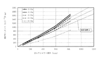
図4に、図2の「インパクト」手前(−0.047s〜0.00s)における、トウダウン現象の部分(図中のマイナス側)の曲げモーメント分布の時間推移を横軸にゴルフシャフトの長さ方向位置を表して示した。
また、原点を通る数本の補助線群Aとゴルフシャフトの略中央を通る補助線郡Bのグラフを示す。
この図から、トウダウンの支配的な曲げモーメントはゴルフシャフトの先端側を中心とする曲げモーメントとグリップ側を中心とする曲げモーメントの複合の負荷がかかっている事がわかる。(図中:○印)後者のグリップ側の曲げモーメント分布は、この補助線群Aとゴルファーがスイングした時の測定値とを対比すると、略補助線群A通りの曲げモーメントがはたらくことが分かる。また、後者のグリップ側の曲げモーメントによるゴルフシャフトのたわみを効果的に抑制できるゴルフシャフトの曲げ剛性分布は、曲げモーメント分布に相似となるゴルフシャフトが「インパクト」手前においても、部分的にしなり具合が変化する「調子」が無く、しなやかなゴルフシャフトの感触を得ることができる。具体的には、先にも述べたように、本発明者らが提案している、ゴルフシャフトの先端からの距離に正比例の関係となる曲げ剛性分布にすることが、効果的である。
一方、ゴルフクラブの略中央を通る補助線群Bとゴルファーがスイングした時の測定値で前者のゴルフシャフトの先端側を中心とする曲げモーメントとを対比すると、略補助線群B通りの曲げモーメント分布を観察することができるが、前者のヘッド側の曲げモーメントによるゴルフシャフトのたわみを効果的に抑制する方法は、未だ解明されていない。
【0015】
即ち、ゴルフシャフトの先端部において、部分的に硬い部分と軟かい部分が存在するため、トウダウンによるたわみ量が大きかったり、ヘッドスピードが遅くなったりするというデメリットが生じ、ゴルファーのスイング毎のばらつきによるしなり方のずれにより打点がばらつき、弾道に影響を与えることになる。
従って、トウダウンによるたわみ量を効率良く小さくし、且つ、ヘッドの走りを抑制せず、且つ、万人に好まれるゴルフシャフトは、実現されていなかった。
【0016】
また、特開平11−206932においては、その実施例において、ゴルフシャフトの先端部分の曲げ剛性1.85×10N・m2に対して、ゴルフシャフトの前方部分の曲げ剛性1.72×10N・m2であり、約1.076倍となっているが、多少のトウダウンの抑制には貢献しているものの、効果は小さいという問題点がある。
【0017】
そこで、ゴルフシャフトのやわらかさ、特にゴルフシャフトの先端部の軟らかさを損なうことなく、インパクト手前のトウダウン量を減らすことで、打点のばらつきを小さくし、且つ、万人に好まれるゴルフシャフトの曲げ剛性分布EI(x)を有するゴルフシャフトを提案する。
【0018】
【課題を解決するための手段】
前記目的を達成するために、本発明の請求項1に記載の発明は、ヘッドが装着される側の端である先端とグリップが装着される側の端であるグリップ端とを備えた繊維強化樹脂製のゴルフシャフトにおいて、前記先端からグリップ端に向かってゴルフシャフト全長の15%〜40%の範囲に、そのゴルフシャフトの曲げ剛性の最小値が存在し、且つ、前記先端からグリップ端に向かってゴルフシャフト全長の10%の範囲の任意の点における曲げ剛性の値が、前記最小値の1.2倍以上2.5倍以下の値に設定するとともに、前記最小値が存在する位置をaとした時、前記位置aからグリップ端に向かって、シャフト全長の60%の位置までの曲げ剛性分布が、原点を通る1次式で近似した場合、その1次式の傾き(N・m 2 /mm)が、±0.003 の範囲内にある、概ね正比例としたことを特徴とするゴルフシャフトである。
【0019】
請求項2の発明は、ヘッドが装着される側の端である先端とグリップが装着される側の端であるグリップ端とを備えた繊維強化樹脂製のゴルフシャフトにおいて、先端よりグリップ端に向かって該ゴルフシャフト全長の15%〜40%の範囲に、そのゴルフシャフトの曲げ剛性の最小値が存在し、且つ、前記最小値が存在する位置から前記先端に向かうに従い、曲げ剛性が漸増し、前記先端からゴルフシャフト全長の10%の範囲の曲げ剛性の最大値が、前記最小値の1.2倍以上2.5倍以下の値に設定するとともに、前記最小値が存在する位置をaとした時、前記位置aからグリップ端に向かって、シャフト全長の60%の位置までの曲げ剛性分布が、原点を通る1次式で近似した場合、その1次式の傾き(N・m 2 /mm)が、±0.003 の範囲内にある、概ね正比例としたことを特徴とするゴルフシャフトである。
【0020】
請求項3の発明は、請求項1又は2記載のゴルフシャフトにおいて、前記位置aから、前記グリップ端より前記先端側に200mmの位置までの曲げ剛性分布が、原点を通る1次式で近似した場合、その1次式の傾き(N・m 2 /mm)が、±0.003 の範囲内にある、概ね正比例であるゴルフシャフトである。
【0025】
【発明の実施の形態】
本発明の実施の形態について図面を基に説明する。
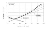
図1は、本発明の実施例であるゴルフシャフト2の曲げ剛性分布EI(x)を示すグラフで、後述する図5に示すようにこのゴルフシャフトの先端2aにはヘッド3が装着され、グリップ端2b側にはグリップ4が装着されてゴルフクラブ1とされるものである。この図1においては、先端2a;x=0を基点とする補助線群A及びクラブ長さの略中央部を基点とする補助線群Bも各々3本ずつ表示している。
補助線郡Bの基点となるクラブ長さの略中央部は、図4における83mm、328mmのトウダウン方向の曲げモーメントの分布の1次式のx軸(y=0)との交点である。この交点は、ゴルファーのスイングにより多少異なるが、概ね、ゴルフシャフトの略中央部に存在することが、複数のデータより既知である。従って、補助線群Bはゴルフシャフトの略中央部を基点とした傾き、切片の異なる1次式で表した。
【0026】
図1に示す実施例のゴルフシャフト2は全長が1143mmである。そして前記先端2aからグリップ端2b側へ向かって、該ゴルフシャフト全長の15%〜40%の範囲である170mmの位置から450mmの位置までの間に、そのゴルフシャフト2の曲げ剛性の最小値2.0×10N・m2が存在する。
同時に、前記先端2aから該ゴルフシャフト全長の10%の範囲には、曲げ剛性の値が、前記最小値の1.2倍以上2.5倍以下の値2.4×10N・m2〜5.0×10N・m2に設定された任意の点が存在している。このような構成とすることにより、先端2aから前記最小値を含む部分である先端部での「コック開放」から「インパクト」の間に発生するトウダウンによるたわみ量を抑制することが出来る。
【0027】
図4に示された、トウダウン現象の部分(図中のマイナス側)の曲げモーメント分布のグラフには補助線群Aと、群Bが示されている。
トウダウンの支配的な曲げモーメントはゴルフシャフトの先端2a側を中心とする曲げモーメントとグリップ4側を中心とする曲げモーメントの複合の負荷がかかっており、グリップ側を中心とする曲げモーメントは補助線群Aで表されることは前にも述べた。この図では、「コック開放」から「インパクト」直前までのヘッドの慣性力による曲げモーメントを表している。
【0028】
ゴルフシャフトの先端2a側を中心とする曲げモーメントは、図5に示すゴルフクラブ1をスイングした時にヘッド3にかかる遠心力によるものが支配的である。
具体的に説明すると、図6に示すように、どんなゴルファーでも、「インパクト」手前において、グリップ4部分とヘッド重心Gは、多少のずれはあるものの、概ねスイングプレーンP上に存在している。そして、「インパクト」時においては、ヘッドスピードがスイング中で最大となり、ヘッド3には遠心力Fが作用する。(図6の矢印のベクトル方向)その時のゴルフシャフト2のトウダウン方向の撓み具合を考えてみると、グリップ4側からゴルフシャフト2の中央Cにかけては、多少のしなりはあるが、概ねスイングプレーンP上に存在しているため、遠心力による曲げモーメントは殆どゼロに近い。しかしながら、概ねゴルフシャフトの中央Cから先端2a側にかけては、ゴルフシャフト2のたわみで徐々にスイングプレーンPからのずれyも大きくなる。これは、ヘッド重心Gがゴルフシャフト2の中心軸P1からオフセットしているのと、遠心力Fが作用するためである。それゆえに、ゴルフシャフト2にかかるゴルフシャフト2の前記中央部Cから先端2aにかけての曲げモーメント分布は、「F×y」(座屈時の曲げモーメント=遠心力F×スイングプレーンからのゴルフシャフトの各位置のずれ(=ゴルフシャフトの撓み)y)で表され、概ねゴルフシャフトの中央Cから先端2a側にかけて、曲げモーメントが概ね線形的に大きくなる。前述した補助線群Bは、インパクト手前のヘッドにかかる遠心力Fによる、ゴルフシャフト2の前記中央部Cから先端2aにかけての曲げモーメント分布;「F×y」に概ね相当するの曲げモーメント分布図を表している。
【0029】
ここで、遠心力Fに関して、説明する。
ヘッド質量をm(=約0.2kg),回転半径、即ち、クラブ長さをL(=約1.0m)として、ヘッドスピードVのとき、ヘッドにかかる遠心力Fは、以下のようになる。
V=30m/sのときは、次式のとおりである。
【0030】
【数1】
F30=m×V2/L=0.2kg×(30m/s)2/1.0m=180N(=18.4kgf)
V=40m/sのときは、次式のとおりである。
【0031】
【数2】
F40=0.2kg×(40m/s)2/1.0m=320N(=32.7kgf)
V=50m/sのときは、次式のとおりである。
【0032】
【数3】
F50=0.2kg×(50m/s)2/1.0m=500N(=51.0kgf)
【0033】
一般的に、ゴルフシャフトの中心軸からヘッドの重心位置までの距離(オフセット)は、30〜50mmである。ここで、スイングプレーンP上にヘッド重心Gの位置が仮に存在すると仮定すると、ゴルフシャフトの先端の撓みは、30〜50mmである。仮に、そのたわみが30mmとすると、ヘッドスピードVが30m/sのとき、ゴルフシャフトの先端部にかかる曲げモーメントMは、18.4kgf×30mm=552kgf・mm(5.4N・m)である。
また、ヘッドスピードVが40m/sのとき、ゴルフシャフトの先端部にかかる曲げモーメントMは、32.7kgf×30mm=981kgf・mm(9.6N・m)である。
更に、ヘッドスピードVが50m/sのとき、ゴルフシャフトの先端部にかかる曲げモーメントMは、51.0kgf×30mm=1530kgf・mm(14.9N・m)である。
(因みに、図4に示すデータは、被験者のヘッドスピードが45m/sのゴルファーであり、オーダー的にほぼ合っていると思われる。)
【0034】
前述したように、ゴルフシャフトの曲げ剛性分布EI(x)を前記曲げモーメント分布に近似させたゴルフシャフトの曲げ剛性分布EI(x)とすることが、トウダウンを抑制すると共に、「トップ・オブ・スイング」や「コック開放」時においても、更に、「インパクト」手前においても、概ね部分的にしなり具合が変化する「調子」が無いゴルフシャフトとすることができ、くせの無く、しなやかなゴルフシャフトの感触を得ることができる。
【0035】
従って、先端部の曲げ剛性の分布は、前記最小値の部分から先端2aに行くに従い、曲げ剛性の値が前記最小値の1.2倍以上2.5倍以下の範囲内で漸増していることにより、「インパクト」手前に、ゴルフシャフトの先端2a側に負荷される曲げモーメントによって生じるトウダウンによるたわみ量を効果的に抑制できる。
【0036】
ゴルフシャフト全長の15%〜40%の範囲に、該ゴルフシャフトの曲げ剛性の最小値が存在すべき理由に関しては、図4の各補助線群A、Bの交点の範囲が300mm〜400mm強の範囲に存在するが、ヘッドスピードの様々なゴルファーへの対応とスイングの個人差を考慮すると、ゴルフシャフトの先端部側の曲げモーメントは、300kgf・mm(2.9N・m)弱のゴルファーも存在する。その際の補助線を引くと、その交点は、200mm前後にも存在することになる。(クラブ長さ=45”のとき。)以上を考慮すると、200mm弱から400mm強の範囲に該ゴルフシャフトの曲げ剛性の最小値が存在すべきであり、クラブ長さの比率で表すと、15%〜40%の範囲となる。
【0037】
その位置がゴルフシャフト全長の15%より小さいと、曲げ剛性の最小値がゴルフシャフトの先端部側に存在するため、逆にトウダウンによるたわみ量が大きくなり、打点位置や弾道に影響を与える。逆に、その位置がゴルフシャフト全長の40%より大きいと、ゴルフシャフトの先端部側の曲げ剛性が大きくなりすぎるなど、ゴルフシャフトとしての全体的な硬さのバランスが悪くなる。
【0038】
ダウンスイングの過程、即ち、「トップ・オブ・スイング」や「コック開放」,更に、「インパクト」手前のスイング中のゴルフシャフトにかかる曲げモーメントの分布は前記したように図4に示すグラフの通りであることが分かっており、このことから、前記曲げモーメントの分布とゴルフシャフトの曲げ剛性の分布に関しては以下の関係が成り立つ。
まず、真直はりのたわみの関係より、数式4が成り立つ。
【0039】
【数4】
d2y/dx2=M(x)/EI(x)
y:たわみ,x:位置,M(x):曲げモーメント,EI(x):曲げ剛性
【0040】
一方、たわみが微小である時、そのたわみ曲線の曲率1/r(x)は、以下の数式5のようにあらわされる。
【0041】
【数5】
1/r(x)=|d2y/dx2|/{1+(dy/dx)2}3/2≒|d2y/dx2|
たわみが微小であり、(dy/dx)2≒0である為。
【0042】
故に、上記の真直はりのたわみの関係式とたわみ曲線の曲率1/r(x)の二つの式より、
【0043】
【数6】
1/r(x)=M(x)/EI(x)となる。
【0044】
得られた前記の式により、スイング中の曲げモーメント分布M(x)とシャフトの曲げ剛性分布EI(x)の比が、そのゴルフシャフトのたわみ形状の程度;曲率=1/r(x)を示す。
即ち、ここで、スイング中のある時刻tにおける曲げモーメント分布M(x)に、シャフト曲げ剛性分布EI(x)が相似形であれば、そのゴルフシャフトの撓みの程度;曲率=1/r(x)は一様である。
【0045】
本発明においては、各々の曲げモーメント分布の時刻tは、「トップ・オブ・スイング」や「コック開放」時であり、又、「インパクト」手前である。
【0046】
本発明の要件を満たすゴルフシャフトを実現するに当たり、図1の補助線に沿った曲げ剛性分布となるゴルフシャフトが、前記の1/r(x)=M(x)/EI(x)の式からも分かるように、最も効果的にトウダウンによるたわみ量を抑制でき、概ね部分的にしなり具合が変化する「調子」が無いゴルフシャフトとなる。
【0047】
さらに、ゴルフシャフト全長としてみた時に、前記した先端部の曲げ剛性特性に加えて、ゴルフシャフトの曲げ剛性分布において、前記最小値が存在する位置をaとしたとき、その位置aからグリップ端2bに向かって、ゴルフシャフト全長の60%の位置までの曲げ剛性分布が、概ね正比例であることが、そのゴルフシャフトのトウダウンによるたわみ量を効果的に抑制でき、部分的にしなり具合が変化する「調子」が無く、故に、くせの無く、しなやかなゴルフシャフトの感触を得ることができる。
より好ましくは、ゴルフシャフト全長としてみた時に、前記した先端部の曲げ剛性特性に加えて、ゴルフシャフトの曲げ剛性分布において、前記最小値が存在する位置をaしたとき、その位置aから、グリップ端2bより先端2aに向かって200mmの位置までの曲げ剛性分布が、概ね正比例であるゴルフシャフトであることが、そのゴルフシャフトのトウダウンによるたわみ量を効果的に抑制でき、部分的にしなり具合が変化する「調子」が無く、故に、くせの無く、しなやかなゴルフシャフトの感触を得ることができる。
【0048】
また、概ね正比例であることとは、先端2aからの位置a(mm)よりグリップ端2bにかけての曲げ剛性分布EI(N・m2)を、原点を通る1次式で近似した場合、その1次式の傾き(Nm2/mm)が±0.003の範囲内にあることを意味し、このような範囲内にあれば、本発明の効果を達成できるからである。±0.003の範囲外になると、部分的にしなり具合が変化する「調子」が存在し、故に、くせを有し、しなやかなゴルフシャフトの感触を得ることができない。
【0049】
本発明の要件を満たすゴルフシャフトを実現するには、強化繊維に合成樹脂を含浸させてなる繊維強化樹脂プリプレグをその巻回する回数、繊維の特性およびその配設角度、厚さ、合成樹脂含浸量などを調整することにより成形できる。また、フィラメントワィンディング製法やブレーディング製法によっても実現可能である。
【0050】
本実施例のゴルフシャフトを成形するにあたっては、成形用のマンドレルの形状を工夫することにより、より容易に形成できる。以下にその一例を示す。
例えば、ウッドシャフトの場合では、図7に示すマンドレル5においてゴルフシャフト2の先端2aから全長の15%〜40%に相当する範囲5aの長さで、好ましく図1における補助線群Aと群Bの交点付近のテーパーを10/1000〜20/1000に設定した。
この位置が、ゴルフシャフト2の全長に対して、15%より小さい時、その位置での曲げ剛性が小さくなりすぎて、ゴルフシャフトがしなりすぎたり、ゴルフシャフトの強度が不足したりする等の問題点を生じる。又、40%より大きい時、先端2a側が硬くなりすぎ、弾道等に影響する。
【0051】
前記テーパーは、10/1000より小さいと、中央部5bのテーパーと変わらず、本発明のゴルフシャフトの曲げ剛性の実現はなく、20/1000より大きいと、テーパーがきつすぎて、炭素繊維強化樹脂のプリプレグがうまくマンドレルに配置できなかったり、曲げ剛性値が最低値の2.5倍より大きくなったりするため、不適切である。
又、図8に示すように、その部分が20/1000程度のテーパーと10/1000程度のテーパーの2段テーパーであっても良い。
【0052】
また、グリップ4に相当する長さ200〜260mmの部分5cテーパーを、0/1000〜5/1000程度の範囲設定し、握りやすさやゴルファーの好みに応じて選定した。
【0053】
残りの部分である中央部に相当する範囲のテーパーを7/1000〜9/1000に設定した。そのテーパーが7/1000より小さかったり、9/1000より大きかったりすると、本発明のゴルフシャフトの曲げ剛性分布において、概ね正比例にはならず、曲げ剛性のバランスが全体的に悪くなり、スイングに影響し、良くない。前記テーパーを有する部分は、ゴルフシャフト全長の約60%程度かそれ以上で、ゴルフシャフト先端部を除く全ての長さに相当する部分でもよい。
【0054】
このように、マンドレルの先端側のテーパーを10/1000〜20/1000に設定したこと、すなわち中央部5bに対し先端5a側に急勾配なテーパー部を設けることで、炭素繊維強化樹脂製ゴルフシャフトの場合、材料を多く使用できることにより、ゴルフシャフトの先端側に行くに従い漸次且つ極端な肉厚の増加が可能となり、ゴルフシャフトの先端よりシャフト全長の15〜40%の範囲に、そのゴルフシャフトの曲げ剛性の最小値が存在し、且つ、ゴルフシャフトの先端よりゴルフシャフト全長の10%の範囲の任意の点の曲げ剛性の値が、その最小値の1.2倍以上2.5倍以下の値に設定したことを特徴とするゴルフシャフトにすることができる。
【0055】
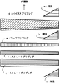
図9に、図7に示すマンドレルに、炭素繊維強化樹脂製のプリプレグシートを積層して形成するシートワィンディング製法により形成されたゴルフシャフトの積層パターンの一例を説明した図を示す。
先端側補強に使用する材料としては、引張り弾性率が230〜500GPaのPAN系炭素繊維からなるプリプレグを用いる。但し、外層側に積層する補強については、引張り弾性率230GPa〜300GPaのPAN系炭素繊維からなるプリプレグを用いる事が好ましい。
230GPa以下であると、図1に示すシャフト曲げ剛性分布EI(x)の先端部の曲線が実現できない。又、最内層の部材に対し、500GPaより大きいと、曲げ剛性値が最低値の2.5倍より大きくなったり、逆に強度不足となったりするため、不適切である。更に、外層側に積層する部材を300GPaより大きくすると、強度不足になる。また、曲げ剛性値が最小となる位置付近においては、応力集中が発生し易く、特に軽量すなわち薄肉シャフトにおいては折損に至る可能性も高くなる為、その様なゴルフシャフトに適応する場合にはフープ層を積層させる事が好ましい。
【0056】
本実施例は、最内層補強a及び補強b、補強cに、東レ(株)製2253F−11(厚み0.0952mm、樹脂含浸量30wt%)を使用した。また、バイアスプリプレグdには、東レ(株)製6255S−11(厚み0.0804mm、樹脂含浸量24wt%)を使用し、フーププリプレグeには、東レ(株)製3051S−5(厚み0.0573mm、樹脂含浸量37wt%)、ストレートプリプレグf及びgには東レ(株)製2253F−13(厚み0.1157mm、樹脂含浸量30wt%)を使用した。
最内層の補強部材aの長さは、ゴルフシャフトの先端部に相当するマンドレルの比較的きついテーパー部の長さに相当する長さに設定した。
【0057】
以上のようにマンドレルを設計し、炭素繊維強化樹脂製プリプレグを積層すると、ゴルフシャフトの先端よりゴルフシャフト全長の15%〜40%の範囲に、そのゴルフシャフトの曲げ剛性の最小値が存在し、且つ、シャフト先端よりシャフト全長の10%の範囲の任意の点の曲げ剛性の値が、その最小値の1.2倍以上2.5倍以下の値に設定したゴルフシャフトを形成することができた。
前記2.5倍より大きな値に設定したシャフトにおいては、通常のスィング時の曲げモーメントと異なった曲げモーメントがかかる場合、例えば、ダフリによる曲げモーメントがかかる場合には折損の可能性があるため、不適切である。
前記1.2倍より小さい値に設定したシャフトにおいては、トウダウン量を増す方向になり、特にヘッドの大型化に伴うオフセット量が増加に対し、この傾向が顕著になる。その結果、打点のばらつきを生むことになる。
フィラメントワィンディング製法によるシャフトや、トウプリプレグによる組み物製法によるシャフトにおいても、このような構成のマンドレルを用いて、その繊維の配設角度や厚みを調整することで、本発明の曲げ剛性分布を有するシャフトを形成することが出来る。
【0058】
【発明の効果】
効果確認の為、試打を実施。同一のヘッドで、本発明シャフトを装着したクラブと、従来シャフトを装着したクラブの比較による試打評価を実施した。
以下、本発明シャフト付きクラブの評価を以下に示す。
・プロK:フレックスSRのシャフトに対して、シャフトのしなりを感じて、良い。フレックスRのシャフトに対して、非常に軟らかく感じるが、振るとそうでもない。捕まる弾道である。非常に楽である。誰でも打てるクラブ。
・プロT:打球が捕まる、粘る感じがする。シャフトのしなり方が良い。
・プロH:フックにしにくく、コントロール性が良い。
・アマYM:シャフトがしなり、球筋も良く、振りやすい。球がなかなか落ちない感じで、飛ぶ。
・アマYB:打球が捕まり、良い。
【図面の簡単な説明】
【図1】本発明のゴルフシャフトの曲げ剛性値を説明するグラフ。
【図2】スイング時にゴルフシャフトに負荷される曲げモーメントを時間毎に示したグラフ。
【図3】スイング時にゴルフシャフトに負荷される曲げモーメントをゴルフシャフト長さの位置に応じて示したグラフ。
【図4】トウダウン現象の部分の曲げモーメント分布を示すグラフ。
【図5】本発明のゴルフシャフトを装着したゴルフクラブの説明図。
【図6】トウダウン現象を説明する図。
【図7】マンドレルを説明する図。
【図8】マンドレルを説明する図。
【図9】実施例のゴルフシャフトのシートワインディング成形を説明する図。
【符号の説明】
1 ゴルフクラブ
2 ゴルフシャフト
2a 先端
2b グリップ端
3 ヘッド
4 グリップ
5 マンドレル
5a 先端側
5b 中央部
5c グリップ
a プリプレグ
b プリプレグ
c プリプレグ
d プリプレグ
e プリプレグ
f プリプレグ
g プリプレグ
G ヘッド重心
P スイングプレーン
P1 中心軸
y ずれ[0001]
BACKGROUND OF THE INVENTION
The present invention provides a golf ball having a bending rigidity distribution in which variation in hitting point is reduced by reducing the amount of deflection due to toe down at the time of swing without impairing the softness of the tip portion on the side where the head of the golf shaft is mounted. Related to the shaft.
[0002]
[Prior art]
When the golfer swings the golf club, the back swing from the “address” goes to “top of swing”, then the down swing goes to “cock open”, “impact”, then the follow-through and “finish” , The golf shaft is most likely to deform and change during the downswing from “Top of Swing” to “Impact”. To affect.
From the “top of swing” to the “cock open” during the downswing, a bending moment centered on the grip portion of the golf shaft acts on the entire length of the golf shaft mainly by the inertial force applied from the head.
[0003]
However, from “cock open” to “impact”, the center of gravity of the head exists slightly away from the shaft axis, and the face of the head changes in various directions with respect to the swing plane during the swing. In addition, the golf shaft is complicatedly deformed due to the fact that the centrifugal force applied to the head acts. In particular, this tendency is often observed at the tip portion.
[0004]
Specifically, in “open cock” to “impact”, the face surface of the head is generally a square (vertical surface) with respect to the head moving direction, but the deformation of the golf shaft bends with respect to the head moving direction. The presence or absence of this bending is one of the factors that lead to an increase in head speed, that is, an increase in flight distance.
In “open cock” to “impact”, as described above, the face surface of the head is generally square, but golf in a direction perpendicular to the traveling direction of the head, that is, toward the heel side of the head. Deformation of shaft bending occurs. This phenomenon of becoming the heel side of the head is generally called “toe down” (or droop in English: DROOP), and the amount of movement is called the amount of deflection due to toe down.
[0005]
Increasing the bend in the direction of travel of the head, especially by reducing the flexural rigidity of the tip of the golf shaft, increasing the bend, and increasing the hitting angle of the hit ball, aiming to increase the flight distance For example, those disclosed in JP-A-11-76479 are known. However, if the design is aimed too much at the effect of increasing the bending of the head in the direction of travel, conversely, the amount of deflection due to toe down increases, resulting in increased variation in the golfer's swing and This will increase the variation of the hit position and the trajectory. In order to solve this problem, it is easy to increase the bending rigidity of the front end portion of the golf shaft. However, if the bending rigidity is increased too much, the bending effect on the traveling direction of the head is reduced.
[0006]
On the other hand, it is already known to increase the bending rigidity of the tip of the golf shaft due to the problem of the strength of the golf shaft. In other words, when the ball is hit off-center of the head, the golf shaft near the end of the hosel part of the head where the tip of the golf shaft is inserted and fixed may be broken due to stress concentration, etc. Therefore, the tip of the golf shaft is well reinforced. By doing so, the bending rigidity of the tip portion of the golf shaft inevitably increases as a whole.
[0007]
Japanese Patent Application Laid-Open No. 11-206932 discloses a technique that considers the distribution of the bending rigidity at the tip of the golf shaft. In the present invention, the shaft tip portion of the shaft of a conventional female golf club is suppressed to a certain low rigidity, so that when the ball is hit, the blur at the tip portion of the shaft having low rigidity is large. If the ball is not caught by the core of the head, the ball will not be stable. The problem is that “the shaft in the range of less than 20% of the total shaft length from the shaft tip is the tip portion, and the shaft length is from 25 to 30% from the shaft tip. The shaft in the range of 20 to 35% is defined as the front portion, the shaft in the range from the shaft end side portion of the front portion to the shaft end is defined as the rear portion, and the bending rigidity of the tip portion is 5 than the bending rigidity of the front portion. The problem is solved by making the golf shaft ˜15% increased and the bending stiffness of the front part is set to the minimum in the longitudinal direction of the shaft ” It is intended to refer.
[0008]
When a golfer swings a golf club, a bending moment is applied over the entire length of the golf shaft, which complicates the golf shaft. FIG. 2 shows the bending moment applied to a golf shaft when a senior golfer swings a golf club with four strain gauges attached to a golf club shaft at approximately equal intervals and perpendicular to the face surface of the head. It is time transition. The positions where the strain gauges are affixed are 83 mm, 328 mm, 578 mm, and 828 mm from the head.
[0009]
In FIG. 2, 0.00 s corresponds to “impact” and a peak is observed at about −0.20 s, which corresponds to “top of swing”. Further, a peak is also observed between about −0.15 s and −0.10 s, which corresponds to “cock open” during downswing. On the other hand, negative peaks are seen before the “impact”, and these are bending moments causing the phenomenon of “toe down”.
Although these waveforms have large and small time differences depending on the golfer, it is proved by a lot of experimental data that they are always seen, and a representative example is shown here.
[0010]
FIG. 3 shows the distribution of bending moments at −0.35 s, −0.30 s, −0.25 s, −0.20 s, and −0.15 s shown in FIG. The position and the vertical axis are shown as bending moments.
In addition, several auxiliary line groups A passing through the origin are also shown. This auxiliary line group A has a load of 1.6 kg to 1.8 kg on the head with the grip portion fixed (generally, when a general golfer swings, when “top of swing” or “cock open”) The inertial force applied to the head) is a distribution diagram of the bending moment of the entire golf shaft. When the auxiliary line group A and the measured value when the golfer swings are compared, the “top of swing” It can be seen that a bending moment substantially in the auxiliary line group A works during the "opening of the cock".
[0011]
Based on these facts, the present inventors have invented a golf shaft having a bending stiffness distribution EI (x) in which the bending stiffness distribution EI (x) of the golf shaft is approximated to the bending moment distribution (Japanese Patent Application No. 2000-366594). ). Specifically, by making the golf shaft a bending stiffness distribution that is directly proportional to the distance from the tip, the bent shape of the golf shaft during the downswing can be made into an approximate arc shape, There is no “tone” in which the degree of bending changes partially. Therefore, it is possible to obtain a flexible golf shaft feel without habit.
[0012]
[Patent Document 1]
Japanese Patent Laid-Open No. 11-76479
[0013]
[Patent Document 2]
JP-A-11-206932
[0014]
[Problems to be solved by the invention]
FIG. 4 shows the length of the golf shaft with the horizontal axis representing the time transition of the bending moment distribution in the portion of the toe down phenomenon (minus side in the figure) just before the “impact” in FIG. 2 (−0.047 s to 0.00 s). The direction position is shown.
Moreover, the graph of the several auxiliary line group A which passes along an origin, and the auxiliary line group B which passes along the approximate center of a golf shaft is shown.
From this figure, it can be seen that the dominant bending moment of the toe down is a composite load of a bending moment centered on the golf shaft tip side and a bending moment centered on the grip side. (In the figure: ○ mark) The bending moment distribution on the grip side of the latter shows that when the auxiliary line group A is compared with the measured value when the golfer swings, a bending moment substantially in the auxiliary line group A works. . In addition, the bending stiffness distribution of the golf shaft that can effectively suppress the deflection of the golf shaft due to the bending moment on the grip side is partially bent even before the impact of the golf shaft similar to the bending moment distribution. There is no “tone” that changes, and a soft golf shaft feel can be obtained. Specifically, as described above, it is effective to have a bending stiffness distribution that is proposed by the present inventors and has a direct proportional relationship with the distance from the tip of the golf shaft.
On the other hand, when the auxiliary line group B passing through the approximate center of the golf club is compared with the bending moment centered on the front end side of the former golf shaft in the measured value when the golfer swings, the bending moment approximately in the auxiliary line group B is obtained. Although the distribution can be observed, a method for effectively suppressing the deflection of the golf shaft due to the bending moment on the former head side has not yet been elucidated.
[0015]
That is, the golf shaft has a hard part and a soft part at the tip part, which causes a disadvantage that the amount of deflection due to toe down is large and the head speed is slow, and due to variations in golfer swings. The hit points vary due to the deviation of the bending method, which affects the trajectory.
Therefore, a golf shaft that efficiently reduces the amount of deflection due to toe down, does not suppress the running of the head, and is preferred by everyone has not been realized.
[0016]
In JP-A-11-206932, in that embodiment, the bending rigidity of the tip portion of the golf shaft is 1.85 × 10 N · m.2In contrast, the bending rigidity of the front portion of the golf shaft is 1.72 × 10 N · m.2Although it is about 1.076 times, although it contributes to some toe-down suppression, there is a problem that the effect is small.
[0017]
Therefore, by reducing the toe-down amount before impact without reducing the softness of the golf shaft, especially the softness of the tip of the golf shaft, the variation of the hitting point is reduced and the bending of the golf shaft that is preferred by everyone. A golf shaft having a stiffness distribution EI (x) is proposed.
[0018]
[Means for Solving the Problems]
In order to achieve the above-mentioned object, the invention according to
[0019]
According to a second aspect of the present invention, there is provided a fiber reinforced resin golf shaft having a tip which is an end on a side where a head is attached and a grip end which is an end on which a grip is attached. In the range of 15% to 40% of the total length of the golf shaft, there is a minimum value of the bending rigidity of the golf shaft, and the bending rigidity gradually increases from the position where the minimum value exists toward the tip, The maximum value of the bending stiffness in the range of 10% of the total length of the golf shaft from the tip is set to a value that is not less than 1.2 times and not more than 2.5 times the minimum value, and the position where the minimum value exists is a. When the bending stiffness distribution from the position a to the grip end to the position of 60% of the total shaft length isWhen approximated by a linear expression passing through the origin, the slope of the linear expression (N · m 2 / Mm) is in the range of ± 0.003,It is a golf shaft characterized by being approximately directly proportional.
[0020]
According to a third aspect of the present invention, in the golf shaft according to the first or second aspect, a bending stiffness distribution from the position a to a position of 200 mm from the grip end to the tip side is as follows:When approximated by a linear expression passing through the origin, the slope of the linear expression (N · m 2 / Mm) is in the range of ± 0.003,It is a golf shaft that is generally directly proportional.
[0025]
DETAILED DESCRIPTION OF THE INVENTION
Embodiments of the present invention will be described with reference to the drawings.
FIG. 1 is a graph showing a bending stiffness distribution EI (x) of a golf shaft 2 according to an embodiment of the present invention. As shown in FIG. 5 to be described later, a head 3 is attached to the tip 2a of the golf shaft, and a grip A grip 4 is attached to the end 2b side to form the
The substantially central portion of the club length serving as the base point of the auxiliary line group B is an intersection with the x-axis (y = 0) of the linear expression of the bending moment distribution in the toe-down direction of 83 mm and 328 mm in FIG. Although this intersection differs somewhat depending on the golfer's swing, it is known from a plurality of data that it is generally present at the approximate center of the golf shaft. Accordingly, the auxiliary line group B is expressed by a linear expression with different inclinations and intercepts from the substantially central portion of the golf shaft.
[0026]
The golf shaft 2 of the embodiment shown in FIG. 1 has a total length of 1143 mm. The minimum value 2 of the bending rigidity of the golf shaft 2 from the position of 170 mm to the position of 450 mm, which is in the range of 15% to 40% of the total length of the golf shaft, from the tip 2a toward the grip end 2b. .0 × 10N ・ m2Exists.
At the same time, in the range of 10% of the total length of the golf shaft from the tip 2a, the value of the bending rigidity is a value 2.4 × 10 N · m that is 1.2 times or more and 2.5 times or less of the minimum value.2~ 5.0 × 10N ・ m2An arbitrary point set to exists. By adopting such a configuration, it is possible to suppress the amount of deflection due to toe-down that occurs between “cock opening” and “impact” at the tip portion that includes the minimum value from the tip 2a.
[0027]
Auxiliary line group A and group B are shown in the graph of the bending moment distribution in the portion of the toe down phenomenon (minus side in the figure) shown in FIG.
The dominant bending moment of the toe down is a composite load of bending moment centered on the golf shaft tip 2a side and bending moment centered on the grip 4 side. The bending moment centered on the grip side is an auxiliary line. What was represented by group A was also mentioned before. In this figure, the bending moment due to the inertial force of the head from “cock opening” to just before “impact” is shown.
[0028]
The bending moment centered on the tip 2a side of the golf shaft is predominantly due to the centrifugal force applied to the head 3 when the
More specifically, as shown in FIG. 6, in any golf player, the grip 4 portion and the center of gravity G of the head are almost on the swing plane P, although there is some deviation before the “impact”. At the time of “impact”, the head speed becomes maximum during the swing, and the centrifugal force F acts on the head 3. (Vector direction of the arrow in FIG. 6) Considering the degree of deflection in the toe-down direction of the golf shaft 2 at that time, there is some bending from the grip 4 side to the center C of the golf shaft 2, but it is generally a swing plane. Since it exists on P, the bending moment by centrifugal force is almost zero. However, from the center C of the golf shaft to the tip 2a side, the deviation y from the swing plane P gradually increases due to the deflection of the golf shaft 2. This is because the center of gravity G of the head is offset from the central axis P1 of the golf shaft 2 and the centrifugal force F acts. Therefore, the bending moment distribution from the central portion C to the tip 2a of the golf shaft 2 applied to the golf shaft 2 is “F × y” (bending moment at buckling = centrifugal force F × of the golf shaft from the swing plane. It is represented by a displacement of each position (= deflection of the golf shaft) y), and the bending moment increases substantially linearly from the center C of the golf shaft to the tip 2a side. The auxiliary line group B described above is a bending moment distribution diagram corresponding to the bending moment distribution from the center C to the tip 2a of the golf shaft 2 due to the centrifugal force F applied to the head before impact; Represents.
[0029]
Here, the centrifugal force F will be described.
When the head mass is m (= about 0.2 kg), the radius of rotation, that is, the club length is L (= about 1.0 m), and the head speed is V, the centrifugal force F applied to the head is as follows. .
When V = 30 m / s, the following equation is obtained.
[0030]
[Expression 1]
F30= M x V2/L=0.2kg×(30m/s)2/1.0m=180N (= 18.4kgf)
When V = 40 m / s, the following equation is obtained.
[0031]
[Expression 2]
F40= 0.2 kg x (40 m / s)2/1.0m=320N (= 32.7kgf)
When V = 50 m / s, the following equation is obtained.
[0032]
[Equation 3]
F50= 0.2kg x (50m / s)2/1.0m=500N (= 51.0kgf)
[0033]
Generally, the distance (offset) from the central axis of the golf shaft to the center of gravity of the head is 30 to 50 mm. Here, assuming that the position of the center of gravity G of the head is present on the swing plane P, the deflection of the tip of the golf shaft is 30 to 50 mm. Assuming that the deflection is 30 mm, when the head speed V is 30 m / s, the bending moment M applied to the tip portion of the golf shaft is 18.4 kgf × 30 mm = 552 kgf · mm (5.4 N · m).
When the head speed V is 40 m / s, the bending moment M applied to the tip of the golf shaft is 32.7 kgf × 30 mm = 981 kgf · mm (9.6 N · m).
Further, when the head speed V is 50 m / s, the bending moment M applied to the tip of the golf shaft is 51.0 kgf × 30 mm = 1530 kgf · mm (14.9 N · m).
(Incidentally, the data shown in FIG. 4 is a golfer whose subject head speed is 45 m / s, and seems to be almost in order.)
[0034]
As described above, the bending rigidity distribution EI (x) of the golf shaft obtained by approximating the bending rigidity distribution EI (x) of the golf shaft to the bending moment distribution suppresses toe down, and “top-of- The golf shaft can be made into a golf shaft that does not have a “tone” that changes its condition almost partially before the “swing”, “cock open”, and even before the “impact”. You can get the feel of
[0035]
Therefore, the bending stiffness distribution of the tip portion gradually increases within the range of 1.2 times or more and 2.5 times or less the minimum value as the tip portion 2a moves from the minimum value portion. Accordingly, it is possible to effectively suppress the amount of deflection caused by the toe down caused by the bending moment loaded on the tip 2a side of the golf shaft before the “impact”.
[0036]
Regarding the reason why the minimum value of the bending rigidity of the golf shaft should be in the range of 15% to 40% of the total length of the golf shaft, the range of the intersection of the auxiliary line groups A and B in FIG. Although it exists in the range, considering the correspondence to golfers with various head speeds and individual differences in swings, there is also a golfer whose bending moment on the tip side of the golf shaft is less than 300 kgf · mm (2.9 N · m) To do. If the auxiliary line in that case is drawn, the intersection will exist also around 200 mm. (When club length = 45 ″.) Considering the above, there should be a minimum value of the bending rigidity of the golf shaft in the range of slightly less than 200 mm to slightly more than 400 mm. % To 40% of range.
[0037]
If the position is smaller than 15% of the total length of the golf shaft, the minimum value of the bending rigidity exists on the front end side of the golf shaft. On the contrary, if the position is larger than 40% of the total length of the golf shaft, the overall hardness balance of the golf shaft becomes worse, for example, the bending rigidity on the tip side of the golf shaft becomes too large.
[0038]
The distribution of the bending moment applied to the golf shaft during the downswing process, that is, “top of swing”, “cock open”, and swing before “impact” is as shown in the graph of FIG. From this fact, the following relationship is established with respect to the distribution of the bending moment and the distribution of the bending rigidity of the golf shaft.
First, Formula 4 is established from the relationship of straight beam deflection.
[0039]
[Expression 4]
d2y / dx2= M (x) / EI (x)
y: deflection, x: position, M (x): bending moment, EI (x): bending stiffness
[0040]
On the other hand, when the deflection is very small, the
[0041]
[Equation 5]
1 / r (x) = | d2y / dx2| / {1+ (dy / dx)2}3/2≒ | d2y / dx2|
Deflection is minute, (dy / dx)2Because ≒ 0.
[0042]
Therefore, from the above two equations of the straight beam deflection relation and the
[0043]
[Formula 6]
1 / r (x) = M (x) / EI (x).
[0044]
According to the obtained equation, the ratio of the bending moment distribution M (x) during the swing and the bending rigidity distribution EI (x) of the shaft is the degree of the deflection shape of the golf shaft; curvature = 1 / r (x) Show.
That is, here, if the bending moment distribution M (x) at a certain time t during the swing is similar to the shaft bending stiffness distribution EI (x), the degree of bending of the golf shaft; curvature = 1 / r ( x) is uniform.
[0045]
In the present invention, the time t of each bending moment distribution is at the time of “top of swing” or “cock opening” and before “impact”.
[0046]
In realizing a golf shaft that satisfies the requirements of the present invention, a golf shaft having a bending stiffness distribution along the auxiliary line in FIG. 1 is expressed by the
[0047]
In addition to the bending rigidity characteristics of the front end portion when viewed as the total length of the golf shaft, when the position where the minimum value exists is a in the bending rigidity distribution of the golf shaft, the position a is changed to the grip end 2b. On the other hand, the fact that the bending stiffness distribution up to a position of 60% of the total length of the golf shaft is almost directly proportional can effectively suppress the amount of deflection due to toe-down of the golf shaft, and the condition that the bending condition changes partially. Therefore, it is possible to obtain a flexible golf shaft feel without habit.
More preferably, in view of the total length of the golf shaft, in addition to the bending rigidity characteristics of the tip portion described above, when the position where the minimum value exists is a in the bending rigidity distribution of the golf shaft, from the position a, the grip end The golf shaft in which the bending stiffness distribution from 2b to the position of 200mm toward the tip 2a is approximately a direct proportion can effectively suppress the amount of deflection due to toe-down of the golf shaft, and the bending condition changes partially. Therefore, it is possible to obtain a supple golf shaft feel without a habit.
[0048]
Further, being approximately directly proportional means that the bending stiffness distribution EI (N · m) from the position a (mm) from the tip 2 a to the grip end 2 b.2) Is approximated by a linear expression passing through the origin, the slope of the linear expression (Nm2/ Mm) is within the range of ± 0.003, and within this range, the effect of the present invention can be achieved. When it is outside the range of ± 0.003, there is a “tone” in which the bending condition partially changes, and therefore, it has a habit and cannot provide a supple golf shaft feel.
[0049]
In order to realize a golf shaft that satisfies the requirements of the present invention, the number of times a fiber reinforced resin prepreg formed by impregnating a reinforced fiber with a synthetic resin, the number of windings of the fiber, and the angle and thickness of the fiber, the synthetic resin impregnation It can be formed by adjusting the amount. It can also be realized by a filament winding method or a braiding method.
[0050]
In molding the golf shaft of the present embodiment, it can be formed more easily by devising the shape of the molding mandrel. An example is shown below.
For example, in the case of a wood shaft, the length of the
When this position is less than 15% of the total length of the golf shaft 2, the bending rigidity at that position becomes too small, the golf shaft becomes too soft, or the strength of the golf shaft is insufficient. Cause problems. On the other hand, when it is larger than 40%, the tip 2a side becomes too hard, which affects the trajectory and the like.
[0051]
When the taper is smaller than 10/1000, the taper of the
Further, as shown in FIG. 8, the portion may be a two-stage taper having a taper of about 20/1000 and a taper of about 10/1000.
[0052]
Further, a portion 5c taper having a length of 200 to 260 mm corresponding to the grip 4 was set in a range of about 0/1000 to 5/1000, and was selected according to the ease of gripping and the golfer's preference.
[0053]
The taper in the range corresponding to the central portion which is the remaining portion was set to 7/1000 to 9/1000. If the taper is smaller than 7/1000 or larger than 9/1000, the bending rigidity distribution of the golf shaft of the present invention is not substantially proportional, and the balance of bending rigidity is deteriorated as a whole, affecting the swing. And not good. The tapered portion may be about 60% or more of the total length of the golf shaft, or a portion corresponding to the entire length excluding the golf shaft tip.
[0054]
Thus, by setting the taper on the tip side of the mandrel to 10/1000 to 20/1000, that is, by providing the tapered portion on the tip 5a side with respect to the
[0055]
FIG. 9 is a diagram illustrating an example of a lamination pattern of golf shafts formed by a sheet winding method in which a prepreg sheet made of carbon fiber reinforced resin is laminated on the mandrel shown in FIG.
As a material used for the tip side reinforcement, a prepreg made of a PAN-based carbon fiber having a tensile modulus of 230 to 500 GPa is used. However, for the reinforcement laminated on the outer layer side, it is preferable to use a prepreg made of a PAN-based carbon fiber having a tensile elastic modulus of 230 GPa to 300 GPa.
If it is 230 GPa or less, the curve at the tip of the shaft bending stiffness distribution EI (x) shown in FIG. 1 cannot be realized. On the other hand, if it is higher than 500 GPa with respect to the innermost layer member, the bending rigidity value becomes larger than 2.5 times the minimum value, and conversely, the strength becomes insufficient. Furthermore, if the member laminated on the outer layer side is made larger than 300 GPa, the strength becomes insufficient. Also, stress concentration is likely to occur near the position where the bending stiffness value is minimum, and the possibility of breakage is particularly high for light weight or thin-walled shafts. It is preferable to laminate the layers.
[0056]
In this example, 2253F-11 (thickness 0.0952 mm, resin impregnation amount 30 wt%) manufactured by Toray Industries, Inc. was used for innermost layer reinforcement a, reinforcement b, and reinforcement c. Further, 6255S-11 (thickness 0.0804 mm, resin impregnation amount 24 wt%) manufactured by Toray Industries, Inc. is used for the bias prepreg d, and 3051S-5 (
The length of the innermost reinforcing member a was set to a length corresponding to the length of the relatively tight taper portion of the mandrel corresponding to the tip portion of the golf shaft.
[0057]
As described above, when the mandrel is designed and the prepreg made of carbon fiber reinforced resin is laminated, the minimum value of the bending rigidity of the golf shaft exists in the range of 15% to 40% of the total length of the golf shaft from the tip of the golf shaft. In addition, a golf shaft can be formed in which the value of the bending stiffness at an arbitrary point in the range of 10% of the total shaft length from the shaft tip is set to a value that is 1.2 times or more and 2.5 times or less of the minimum value. It was.
In the shaft set to a value larger than 2.5 times, when a bending moment different from the bending moment during normal swing is applied, for example, when a bending moment due to duffing is applied, there is a possibility of breakage. It is inappropriate.
In a shaft set to a value smaller than 1.2 times, the toe-down amount tends to increase, and this tendency becomes particularly prominent as the offset amount increases as the head size increases. As a result, variations in hit points are produced.
The shaft by the filament winding method and the shaft by the assembly method by tow prepreg also have the bending rigidity distribution of the present invention by adjusting the arrangement angle and thickness of the fiber using the mandrel having such a configuration. A shaft can be formed.
[0058]
【The invention's effect】
A test shot was made to confirm the effect. With the same head, a trial hit evaluation was performed by comparing a club equipped with the shaft of the present invention and a club fitted with a conventional shaft.
Hereinafter, evaluation of the club with the shaft of the present invention is shown below.
・ Pro-K: You can feel the bending of the shaft of Flex SR. It feels very soft against the Flex R shaft, but it doesn't. A trajectory to be caught. Very easy. Anyone can hit the club.
・ Pro T: Feels sticky and gets sticky. The shaft bends well.
・ Pro H: Hard to hook and good control.
・ Ama YM: The shaft is bent, the ball is good, and it is easy to swing. It feels like a ball does n’t fall easily.
・ Ama YB: A hit ball is caught and it is good.
[Brief description of the drawings]
FIG. 1 is a graph illustrating a bending rigidity value of a golf shaft of the present invention.
FIG. 2 is a graph showing a bending moment applied to a golf shaft during a swing for each time.
FIG. 3 is a graph showing a bending moment applied to the golf shaft during a swing according to the position of the golf shaft length.
FIG. 4 is a graph showing a bending moment distribution in a toe down phenomenon portion.
FIG. 5 is an explanatory view of a golf club equipped with the golf shaft of the present invention.
FIG. 6 is a diagram illustrating a toe down phenomenon.
FIG. 7 is a diagram illustrating a mandrel.
FIG. 8 is a diagram illustrating a mandrel.
FIG. 9 is a view for explaining sheet winding molding of a golf shaft according to an embodiment.
[Explanation of symbols]
1 Golf club
2 Golf shaft
2a Tip
2b Grip end
3 heads
4 Grip
5 Mandrels
5a Tip side
5b center
5c grip
a Prepreg
b Prepreg
c Prepreg
d Prepreg
e Prepreg
f Prepreg
g Prepreg
G Head center of gravity
P Swing plane
P1 center axis
y shift
Claims (3)
Priority Applications (1)
| Application Number | Priority Date | Filing Date | Title |
|---|---|---|---|
| JP2002287166A JP3933552B2 (en) | 2001-09-28 | 2002-09-30 | Golf shaft |
Applications Claiming Priority (3)
| Application Number | Priority Date | Filing Date | Title |
|---|---|---|---|
| JP2001-300265 | 2001-09-28 | ||
| JP2001300265 | 2001-09-28 | ||
| JP2002287166A JP3933552B2 (en) | 2001-09-28 | 2002-09-30 | Golf shaft |
Publications (2)
| Publication Number | Publication Date |
|---|---|
| JP2003169871A JP2003169871A (en) | 2003-06-17 |
| JP3933552B2 true JP3933552B2 (en) | 2007-06-20 |
Family
ID=26623260
Family Applications (1)
| Application Number | Title | Priority Date | Filing Date |
|---|---|---|---|
| JP2002287166A Expired - Fee Related JP3933552B2 (en) | 2001-09-28 | 2002-09-30 | Golf shaft |
Country Status (1)
| Country | Link |
|---|---|
| JP (1) | JP3933552B2 (en) |
Families Citing this family (7)
| Publication number | Priority date | Publication date | Assignee | Title |
|---|---|---|---|---|
| JP4410668B2 (en) | 2004-12-01 | 2010-02-03 | Sriスポーツ株式会社 | Golf club |
| US7427240B2 (en) | 2006-06-28 | 2008-09-23 | Sri Sports Limited | Shaft for golf clubs and golf club |
| US7524248B2 (en) | 2006-09-19 | 2009-04-28 | Sri Sports Limited | Shaft for golf clubs and golf club |
| JP4362788B2 (en) | 2007-06-12 | 2009-11-11 | Sriスポーツ株式会社 | Manufacturing method of tubular body made of fiber reinforced resin and golf club shaft manufactured by the method |
| JP5202156B2 (en) | 2008-07-24 | 2013-06-05 | ダンロップスポーツ株式会社 | Golf club shaft |
| JP5439259B2 (en) * | 2010-03-31 | 2014-03-12 | グローブライド株式会社 | Golf club shaft set |
| JP2012090730A (en) * | 2010-10-26 | 2012-05-17 | Globeride Inc | Shaft set for golf club and iron set |
-
2002
- 2002-09-30 JP JP2002287166A patent/JP3933552B2/en not_active Expired - Fee Related
Also Published As
| Publication number | Publication date |
|---|---|
| JP2003169871A (en) | 2003-06-17 |
Similar Documents
| Publication | Publication Date | Title |
|---|---|---|
| US7524248B2 (en) | Shaft for golf clubs and golf club | |
| JP5302799B2 (en) | Golf club shaft and golf club | |
| US7427240B2 (en) | Shaft for golf clubs and golf club | |
| JP4528241B2 (en) | Golf club | |
| JP4410668B2 (en) | Golf club | |
| JP7661707B2 (en) | Golf Club Head | |
| JP3540195B2 (en) | Fiber reinforced plastic golf club shaft | |
| JP3933552B2 (en) | Golf shaft | |
| US7300360B2 (en) | Golf club | |
| JP4713529B2 (en) | Golf club shaft and golf club | |
| JP2002085608A (en) | Golf club shaft | |
| JP4955512B2 (en) | Golf club shaft | |
| JP2008148757A (en) | Golf club shaft and golf club | |
| JP2004041418A (en) | Golf club | |
| JP4709429B2 (en) | Golf club | |
| JP4283836B2 (en) | Golf club shaft and golf club | |
| JP2003102883A (en) | Golf club shaft | |
| JP3061252B2 (en) | Golf club set | |
| JP2000279558A (en) | Golf club set and its shaft set | |
| KR101737965B1 (en) | Golf club | |
| JP2002052103A (en) | Golf club shaft | |
| JP2001046564A (en) | Golf club shaft and golf club | |
| JPH11206933A (en) | Golf club shaft | |
| JP6936142B2 (en) | Putter club | |
| JP2002224256A (en) | Golf shaft and golf club to which golf shaft is attached |
Legal Events
| Date | Code | Title | Description |
|---|---|---|---|
| A977 | Report on retrieval |
Free format text: JAPANESE INTERMEDIATE CODE: A971007 Effective date: 20060424 |
|
| A131 | Notification of reasons for refusal |
Free format text: JAPANESE INTERMEDIATE CODE: A131 Effective date: 20060615 |
|
| A521 | Request for written amendment filed |
Free format text: JAPANESE INTERMEDIATE CODE: A523 Effective date: 20060809 |
|
| A131 | Notification of reasons for refusal |
Free format text: JAPANESE INTERMEDIATE CODE: A131 Effective date: 20061201 |
|
| A521 | Request for written amendment filed |
Free format text: JAPANESE INTERMEDIATE CODE: A523 Effective date: 20070124 |
|
| TRDD | Decision of grant or rejection written | ||
| A01 | Written decision to grant a patent or to grant a registration (utility model) |
Free format text: JAPANESE INTERMEDIATE CODE: A01 Effective date: 20070215 |
|
| A61 | First payment of annual fees (during grant procedure) |
Free format text: JAPANESE INTERMEDIATE CODE: A61 Effective date: 20070313 |
|
| R150 | Certificate of patent or registration of utility model |
Ref document number: 3933552 Country of ref document: JP Free format text: JAPANESE INTERMEDIATE CODE: R150 Free format text: JAPANESE INTERMEDIATE CODE: R150 |
|
| FPAY | Renewal fee payment (event date is renewal date of database) |
Free format text: PAYMENT UNTIL: 20130330 Year of fee payment: 6 |
|
| R250 | Receipt of annual fees |
Free format text: JAPANESE INTERMEDIATE CODE: R250 |
|
| FPAY | Renewal fee payment (event date is renewal date of database) |
Free format text: PAYMENT UNTIL: 20160330 Year of fee payment: 9 |
|
| R250 | Receipt of annual fees |
Free format text: JAPANESE INTERMEDIATE CODE: R250 |
|
| R250 | Receipt of annual fees |
Free format text: JAPANESE INTERMEDIATE CODE: R250 |
|
| R250 | Receipt of annual fees |
Free format text: JAPANESE INTERMEDIATE CODE: R250 |
|
| LAPS | Cancellation because of no payment of annual fees |