JP3932497B2 - Two-way switching control valve - Google Patents
Two-way switching control valve Download PDFInfo
- Publication number
- JP3932497B2 JP3932497B2 JP02013798A JP2013798A JP3932497B2 JP 3932497 B2 JP3932497 B2 JP 3932497B2 JP 02013798 A JP02013798 A JP 02013798A JP 2013798 A JP2013798 A JP 2013798A JP 3932497 B2 JP3932497 B2 JP 3932497B2
- Authority
- JP
- Japan
- Prior art keywords
- plunger
- permanent magnet
- valve
- outlet opening
- coil
- Prior art date
- Legal status (The legal status is an assumption and is not a legal conclusion. Google has not performed a legal analysis and makes no representation as to the accuracy of the status listed.)
- Expired - Fee Related
Links
Images


Description
【0001】
【発明の属する技術分野】
本発明は、冷凍・冷蔵システムにおいて冷媒の流路を切り替えるために使用する二方切替制御弁に関し、特に、家庭用冷蔵庫や自動販売機等の少容量の冷凍・冷蔵システムで、膨張器をキャピラリチューブや固定オリフイスとするシステムにおいて、冷媒サイクルに相応して循環冷媒量を調整するため、二つの膨張器を選択することができる冷媒回路用二方切替制御弁に関するものである。
【0002】
【従来の技術】
家庭用冷蔵庫や自動販売機等の少容量の冷凍・冷蔵システムにおいて、膨張器としてキャピラリチューブや固定オリフイスを用いたものにおいては、蒸発器負荷やシステム負荷量に相応した冷媒循環流量はある程度調整することはできるが、制御機能はほとんど備えていないため、近年採用されつつある圧縮器や蒸発器用フアンのインバータ化に対応することができず、また、省エネ運転に対応することができないため、これらに対応することができる装置の開発が望まれている。
【0003】
そのため、冷媒循環回路中に少容量の膨張弁を設け、蒸発器出口温度を検出して温度伝達媒体により直接膨張弁を制御する温度膨張弁や、あるいは電動式リニア膨張弁を用いて電気的に弁開度を制御することが提案されている。しかしながら、上記のような少容量の冷凍・冷蔵システムにおいては、微少流量の冷媒を制御する必要があるため、膨張弁の弁部の加工精度を著しく高度なものとする必要があり、コスト高となるほか、生産性が悪くなる欠点がある。また、微少流量を制御することは微少開度にて動作することから、ごみや異物のつまりが発生し易く、信頼性が著しく低下する欠点もある。
【0004】
したがって、キャピラリチューブを用いた冷媒回路において、負荷に対応するシステムとしては、最も簡素化したシステムとして、たとえば図8(イ)に示すように、あらかじめ決められたキャピラリチューブCT0 を備え、差圧△Pxを発生するようにしている冷媒回路に対して、図8(ロ)に示すように、そのキャピラリチューブCT0 に対して直列に差圧△Pc発生用のキャピラリチューブCT1 を追加接続し、この追加接続するキャピラリチューブCT1 を任意に選択することにより対応することも考えられる。しかしながら、この方式では、キャピラリチューブの特性を変更するために差圧発生用のキャピラリチューブCT1 を追加接続する作業が必要となり、上記のように圧縮機や蒸発器用フアンのインバータ化に対応するような制御性は実質的には有していないので使用することはできない。
【0005】
この点を改良する手段として、たとえば図8(ハ)に示すように、特性の異なる第1キャピラリチューブCT1 と第2キャピラリチューブCT2 を併設し、その各々に電磁弁V1 とV2 を設け、片方の電磁弁に通電させることにより、キャピラリチューブを選択使用することも提案されている。
【0006】
【発明が解決しようとする課題】
上記のような特性の異なる第1キャピラリチューブと第2キャピラリチューブを併設し、その各々に電磁弁を設け、片方の電磁弁に通電しておくことにより、キャピラリチューブを選択使用する方式においては、キャピラリチューブの信頼性を確保でき長所を有する。しかしながら、使用する電磁弁の数が増加することによりコストが上昇し、更に、片方の電磁弁を常時通電しているため、消費電力が増加し省エネに反する結果となる。
【0007】
したがって、本発明は、簡単な構造で消費電力が少なく、長期間確実に作動する二方切替電磁弁を提供することを目的とする。
【0008】
【課題を解決するための手段】
本発明は、上記課題を解決するために、両端に出口開口を有するとともに入口開口を有する弁本体と、各出口開口を開閉する弁体を備えた2個のプランジャと、該両プランジャ間に配置した永久磁石を貫通する中央貫通孔を通して縮設したプランジャばねと、前記弁本体外側の各プランジャの周囲に配置したコイルと、該各コイルへの通電を切り替えるスイッチ回路とからなる二方切替電磁弁において、前記両プランジャのストロークを制限する移動可能なストッパを前記永久磁石の中央貫通孔を通して配置してなる二方切替制御弁を構成したものである。
【0009】
本発明は上記のように構成したので、両コイルに通電していないときに両プランジャ間に配設したプランジャばねにより、両プランジャが相互に離れる方向に付勢され、各プランジャの弁体が、各々対向する出口開口を閉鎖している状態においては、入口開口側の冷媒は両出口開口から出ることはなく、閉鎖状態となっている。この状態からスイッチ回路により片側のコイルに対し、通電したときにプランジャの着磁により永久磁石と引き合う方向に一時的に通電すると、通電されたコイルに対向するプランジャは着磁され、永久磁石と引き合うようになるため高速で移動し、片側の出口開口を開放する。プランジャは永久磁石に吸引保持されるので、コイルへの通電を切っても、プランジャの弁体は、この出口開口を開放する作動を継続する。このとき、他側のプランジャは作動することはなく、弁体は他側の出口開口を閉鎖している。
【0010】
この状態から他側のコイルに対し、通電したときにプランジャの着磁により永久磁石と引き合う方向に一時的に通電すると、通電されたコイルに対向するプランジャは着磁され、永久磁石と引き合うようになるため高速で他側の出口開口を開放する方向に移動する。このとき、移動するプランジャにより両プランジャ間に縮設されたプランジャばねの圧縮力と、両プランジャ間にストッパが配設され、そのストッパの移動により、前記のように出口開口を開放していた片側の弁体を備えたプランジャは、永久磁石の吸引力に抗して出口開口を閉鎖する方向に移動し、この出口開口を閉鎖することにより、入口開口からの流体は他の出口開口側に切り替えられる。出口開口を開放した側のプランジャは永久磁石に吸引保持されるので、前記と同様に、コイルへの通電を切っても、プランジャの弁体はこの出口開口を開放する作動を継続する。
【0011】
更に、弁体の開閉状体がいかなる状態にあっても、両コイルに対し、通電したときにプランジャの着磁により永久磁石と反発する方向に一時的に通電すると、両プランジャともに永久磁石から離れ、後はプランジャばねの反発力によって両プランジャはその弁体で出口開口を閉鎖する方向に移動し、両出口開口が閉鎖されるので、この弁の上流側と下流側は遮断状体を保持する。この状態は両コイルへの通電を遮断しても維持される。
【0012】
【発明の実施の形態】
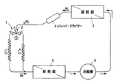
本発明の実施例を図面に沿って説明する。図1は、本発明の二方向切替制御弁が適用される例としての、家庭用冷蔵庫や自動販売機等の少容量の冷凍・冷蔵システムにおいて、膨張器としてキャピラリチューブを用いたシステムを示し、このキャピラリチューブはCT1 とCT2 の2個が併設されている。両キャピラリチューブの上流側には、本発明の二方向切替制御弁1が設けられ、この二方向切替制御弁1の入口開口2は、凝縮器3の出口側に設けたレシーバドライヤー4の出口側に連通している。
【0013】
各キャピラリチューブCT1 とCT2 の出口は連通して蒸発器5の入口管路に接続され、蒸発器5からの冷媒は圧縮機6で圧縮され、高温高圧となった冷媒は凝縮器3で凝縮液化し、再び前記のように循環する。このようなキャピラリチューブの接続と二方切替制御弁の接続状体は、前記図8においては、(ニ)として従来のシステムと比較して示している。
【0014】
このようなシステムで用いられる本発明の二方切替制御弁1は、図2に示すように、図中下端部に第1出口開口10を形成した弁本体11には、この開口10に連通して前記2個のキャピラリチューブの片側である第1キャピラリチューブCT1 と連通する第1出口継手12を固定している。また、弁本体には弁本体内の弁室13に連通するように、弁本体の側部に形成した入口開口2に対して入口継手14を固定している。弁本体11の上部には、弁本体の一部として上方に延びる筒状の非磁性体からなるシリンダ15を固定しており、このシリンダ15の上端部には弁孔部材16が固定され、この弁孔部材16及びシリンダ15の端部を覆うようにカバー17が固定されている。弁孔部材16には第2出口開口18が形成され、出口開口18の周囲には止めナット20が螺合し、カバー17を固定している。出口開口18には第2キャピラリチューブCT2 と連通する第2出口継手21を固定している。
【0015】
シリンダ15内には、図中上下方向に第1プランジャ22と第2プランジャ23が摺動自在に収納され、第1プランジャ22の下端には第1出口開口10を開閉する第1弁体24を備え、第2プランジャ23の上端には、第2出口開口18を開閉する第2弁体25を備えている。各プランジャ22,23の側面には、上下方向に連通する連通溝26が形成され、入口開口2からの冷媒を第2出口開口18に導くようにしている。各プランジャ22,23の対向する底部にはばね収納溝27を備え、両ばね収納溝27間にプランジャばね28を縮設している。また、この両プランジャ22,23の対向する底面間には、永久磁石30がシリンダ15内の第1コイル34と第2コイル35との中心位置に固定されており、その極性は図示するように、下方の面がN極、上方の面がS極になるように設定している。この永久磁石30の中央には貫通孔31が形成され、この中に前記プランジャばね28が貫通しているとともに、プランジャばね28を取り囲むように円筒状のストッパ32を摺動自在に設けている。このストッパ32は、ストッパ32の端部といずれかのプランジャの端面との間に、片側のプランジャのストローク分の遊隙よりわずかに長くなるように設定している。
【0016】
シリンダ15の周囲には、前記シリンダの内部に固定した永久磁石30の上下方向の中心と一致するように中板33が固定され、この中板33の下方には第1コイル34が、また上方には第2コイル35が固定され、その周囲は外函36によって覆われている。第1コイルの下側の巻線37は第1スイッチ38の第1端子Aに、第1コイル34の上側巻線40及び第2コイルの下側巻線41は共通の第2スイッチ42の第1端子Aに接続され、第2コイル35の上側巻線43は第3スイッチ44の第1端子Aに接続されている。
【0017】
第1スイッチ38の第2端子B、第2スイッチ42の第2端子B、及び第3スイッチ44の第3端子Cは線Pにより電源のプラス極側に接続され、第1スイッチ38の第3端子C、第2スイッチ42の第3端子C及び第3スイッチ44の第2端子Bは線Mにより電源のマイナス極側に接続されている。図2に示す状態では、第1スイッチ38の第1端子Aと第2端子Bが接続され、第2スイッチ42の第1端子Aと第2端子Bが接続され、第3スイッチ44の第1端子Aと第3端子Cが接続される結果、第1コイル34及び第2コイル35とも下側巻線と上側巻線ともに+電極と接続されるため、各コイルは通電されず、各プランジャはプランジャばね28により互いに離反する方向に付勢され、両プランジャの弁体により第1出口及び第2出口が閉鎖されている。それにより、図1の冷媒回路において、圧縮機出口側と圧縮機入口側の管路がシールされ、このような状態においては、冷凍システムが非作動時に、コイルに電流を供給することなしに両管路は遮断状態が保持され、圧縮冷媒が保持されるため、次に冷凍システムを作動するときにこの圧縮冷媒の存在により直ちに冷凍システムが立ち上がる。その結果、エネルギー消費の少ない効率の良い、しかも直ちに冷凍システムを立ち上げることが可能なシステムとすることができる。
【0018】
このようなスイッチの切替状態から、図3に示すように、第1スイッチ38のみ第2端子Bから第3端子Cにt1 からt2 までの△tの間切り替えると、第1コイル34の下側巻線37がマイナスに、上側巻線40がプラス側に通電されるので、第1プランジャ22は下側がN極に、上側がS極となり、永久磁石と引き合う磁極配列となるので、第1プランジャ22は永久磁石30に引き上げられ、第1弁体24は第1出口開口10を開放する。このとき、第1プランジャ22が永久磁石30の面に当接する前に、ストッパ32の長さが各プランジャのストローク分よりわずかに長く設定しているので、ストッパ32の上側の端部が、第2プランジャ23の端面に当接して停止した状態において、第1プランジャ22の端部がストッパ32の下側の端部に当接するので、第1プランジャ22が永久磁石30に衝突することがなく、騒音を発生することがない。この状態から上記時間t2 において第1スイッチ38が第3端子側Cから第2端子側Bに戻され、第1コイル34の下側巻線37も上側巻線40もともにプラス極に接続される結果、通電されない状態となっても、永久磁石30は第1プランジャ22を吸引保持しているので、この第1出口開口10を開放し、第1キャピラリチューブCT1 を使用する状態を維持する、いわゆるラッチ作用をなす。
【0019】
一方、図2に示す状態から、図4に示すように、第3スイッチ44のみ第3端子Cから第2端子Bにt1 からt2 までの△tの間切り替えると、第2コイル35の下側巻線41がプラスに、上側巻線43がマイナス側に通電されるので、第2プランジャ23は下側がN極に、上側がS極となり、永久磁石と引き合う磁極配列となるので、第2プランジャ23は永久磁石30に引き下げられ、第2弁体25は第2出口開口18を開放する。この場合も、ストッパ32がプランジャと永久磁石の直接当接防止作用をなし、騒音を減少することができる。この状態から上記時間t2 において第3スイッチ44が第2端子側Bから第3端子側Cに戻され、第2コイル35の下側巻線41も上側巻線43もともにプラス極に接続される結果、通電されない状態となっても、永久磁石30は第2プランジャ23を吸引保持しているので、この第2出口開口18を開放し、第2キャピラリチューブCT2 を使用する状態を維持する。
【0020】
上記図3に示す第1キャピラリチューブCT1 を使用している状態を継続しているときに、冷凍システムの負荷等の変化により第2キャピラリチューブCT2 を使用することが適切となったときには、第1乃至第3スイッチのすべてがプラス側に接続されている状態から、図4に示すように、第3スイッチ44のみ第3端子Cから第2端子Bにt1 からt2 までの△tの間切り替えると、前記と同様に作動し、第2プランジャ23は永久磁石30に引き下げられ、第2弁体25は第2出口開口18を開放することとなるが、このとき、第1プランジャ22と第2プランジャ23間に設けられたストッパ32が第1プランジャ22を強制的に押し下げ、第1プランジャ22は永久磁石30から切り離されて下方に移動する。その結果、第2プランジャ23が永久磁石30に吸引保持されている状態では、第1プランジャ22はその力で第1弁体24を第1出口開口10に押しつけて閉鎖する。この状態から上記時間t2 において第3スイッチ44が第2端子側Bから第3端子側Cに戻され、第2コイル35の下側巻線41も上側巻線43もともにプラス極に接続される結果、通電されない状態となっても、永久磁石30は第2プランジャ23を吸引保持しているので、この第2出口開口18を開放し、第2キャピラリチューブCT2 を使用するとともに、ストッパ32により第1出口開口を閉鎖する状態を維持する。
【0021】
また、図4に示す第2キャピラリチューブCT2 を使用している状態を継続しているときに、冷凍システムの負荷等の変化により第1キャピラリチューブCT1 を使用することが適切となったときには、第1乃至第3スイッチのすべてがプラス側に接続されている状態から、図3に示すように、第1スイッチ38のみ第2端子Bから第3端子Cにt1 からt2 までの△tの間切り替えると、前記と同様に作動し、第1プランジャ22は永久磁石30に引き上げられ、第1弁体24は第1出口開口10を開放することとなるが、このとき、第1プランジャ22と第2プランジャ23間に設けられたストッパ32が第2プランジャ23を強制的に押し上げ、第2プランジャ23は永久磁石30から切り離されて上方に移動する。その結果、第1プランジャ22が永久磁石30に吸引保持されている状態では第2プランジャ23は、その力で第2弁体25を第2出口開口18に押しつけて閉鎖する。この状態から上記時間t2 において第1スイッチ38が第3端子Cから第2端子側Bに戻され、第1コイル34の下側巻線37も上側巻線40もともにプラス極に接続される結果、通電されない状態となっても、永久磁石30は第1プランジャ22を吸引保持しているので、この第1出口開口10を開放し、第1キャピラリチューブCT1 を使用するとともに、ストッパ32により第2出口開口18を閉鎖する状態を維持する。
【0022】
更に、上記図3または図4に示す運転状態を継続し、すべてのスイッチがプラス側に接続されている状態から、図5に示すように、t1 からt2 までの△tの間、第2スイッチ42のみマイナス側に切り替えると、第1プランジャ22と第2プランジャ23はともに永久磁石30と反発する磁極に励磁されるので、第1プランジャ22の第1弁体24は第1出口開口10を閉鎖し、第2プランジャ23の第2弁体25は第2出口開口18を閉鎖する。
【0023】
上記実施例においては、ストッパ32の長さを、ストッパ32の端部といずれかのプランジャの端面との間に、片側のプランジャのストローク分のより幾分長い長さに設定したものであるが、このストッパ32の長さを短くするかあるいはなくすことにより、図6に示すように、第2スイッチ42をプラス側に、他のすべてのスイッチをマイナス側に通電切り替えすると、各プランジャはともに永久磁石に吸引されるように励磁され、引きつけられるので、第1出口開口及び第2出口開口ともに開放され、この状態から第2スイッチをマイナス側に切替、あるいは第1スイッチ及び第3スイッチをプラス側に切り替えると、各コイルは通電されない状態となり、各弁は開放状体を維持する。従って、この状態では第1キャピラリチューブCT1及び第2キャピラリチューブCT2 が並列接続されて運転され、膨張器の第3の態様を得ることとができる。
【0025】
また、上記実施例では、キャピラリチューブを用いた冷凍回路について述べたが、キャピラリチューブのほかに固定オリフイス等を用いた冷凍システムに用いることもできる。
【0026】
【発明の効果】
本発明は上記のように構成したので、コイルを2個設けることにより確実な弁作動を行うことができ、また、コイルは瞬時通電のみを考慮するだけでよいので小型のものとすることができる。更に、瞬時通電のみで所定の状態を維持するラッチ作用を行うので消費電力を少なくすることができる。また、上記二方弁の開閉により、冷媒回路の高圧側と低圧側を遮断する回路を構成することができるので、停止時間の延長と起動時等に省エネルギー効果を奏することができる。
【0027】
両プランジャ間にプランジャのストロークを制限するストッパを配置してなるものであるから、一方の弁が開き他方の弁が閉じている一方弁開の保護効果を有するので、電磁弁特有の弁閉時の衝撃音を低減することができる。このように、簡単な構造で消費電力が少なく、長期間確実に作動する二方切替制御弁とすることができる。
【図面の簡単な説明】
【図1】本発明の二方切替制御弁を適用する冷凍回路図である。
【図2】本発明の実施例の第1の作動態様を示す断面図である。
【図3】同第2の作動態様を示す断面図である。
【図4】同第3の作動態様を示す断面図である。
【図5】同第4の作動態様を示す断面図である。
【図6】本発明の他の実施例の断面図である。
【図7】キャピラリチューブの接続態様を示す図である。[0001]
BACKGROUND OF THE INVENTION
The present invention relates to a two-way switching control valve used for switching a refrigerant flow path in a refrigeration / refrigeration system, and more particularly to a small-capacity refrigeration / refrigeration system such as a home refrigerator or a vending machine, where an expander is a capillary. The present invention relates to a two-way switching control valve for a refrigerant circuit in which two expanders can be selected in order to adjust the amount of refrigerant circulated in accordance with the refrigerant cycle in a tube or fixed orifice system.
[0002]
[Prior art]
In a small-capacity refrigeration / refrigeration system such as a home refrigerator or vending machine that uses a capillary tube or a fixed orifice as an expander, adjust the refrigerant circulation flow rate corresponding to the evaporator load and system load to some extent. However, since it has few control functions, it cannot be used for inverters in compressors and evaporator fans that have been adopted in recent years, and it cannot handle energy-saving operation. Development of an apparatus that can cope with this is desired.
[0003]
Therefore, a low-capacity expansion valve is provided in the refrigerant circulation circuit, and the temperature is controlled electrically by using a temperature expansion valve that detects the evaporator outlet temperature and directly controls the expansion valve using a temperature transmission medium, or an electric linear expansion valve. It has been proposed to control the valve opening. However, in the low-capacity refrigeration / refrigeration system as described above, since it is necessary to control a very small amount of refrigerant, it is necessary to make the processing accuracy of the valve portion of the expansion valve extremely high, which increases the cost. In addition, there is a drawback that productivity is deteriorated. Moreover, since controlling the minute flow rate operates at a minute opening, there is a disadvantage that dust and foreign matter are easily clogged and reliability is significantly lowered.
[0004]
Thus, in the refrigerant circuit using a capillary tube, as the system corresponding to the load, as the most simplified system, for example, as shown in FIG. 8 (b), provided with a capillary tube CT 0 to a predetermined differential pressure As shown in FIG. 8B, a capillary tube CT 1 for generating a differential pressure ΔPc is additionally connected in series to the capillary tube CT 0 to the refrigerant circuit that generates ΔPx. It is also conceivable to cope by arbitrarily selecting the capillary tube CT 1 to be additionally connected. However, in this method, it is necessary to additionally connect a capillary tube CT 1 for generating a differential pressure in order to change the characteristics of the capillary tube, so as to cope with the inverter conversion of the compressor and the evaporator fan as described above. Since it has virtually no controllability, it cannot be used.
[0005]
As means for improving this point, for example, as shown in FIG. 8C, a first capillary tube CT 1 and a second capillary tube CT 2 having different characteristics are provided, and electromagnetic valves V 1 and V 2 are respectively provided. It has also been proposed to selectively use a capillary tube by providing and energizing one of the solenoid valves.
[0006]
[Problems to be solved by the invention]
In the method of selecting and using a capillary tube by providing a first capillary tube and a second capillary tube having different characteristics as described above, providing a solenoid valve for each, and energizing one of the solenoid valves, The reliability of the capillary tube can be ensured, and there are advantages. However, the cost increases due to an increase in the number of solenoid valves to be used, and furthermore, since one of the solenoid valves is always energized, the power consumption increases, which is contrary to energy saving.
[0007]
Therefore, an object of the present invention is to provide a two-way switching electromagnetic valve that has a simple structure, consumes less power, and operates reliably for a long period of time.
[0008]
[Means for Solving the Problems]
In order to solve the above problems, the present invention provides a valve body having outlet openings at both ends and having inlet openings, two plungers having valve bodies for opening and closing each outlet opening, and disposed between the plungers. Two-way switching solenoid valve comprising a plunger spring contracted through a central through hole penetrating the permanent magnet, a coil disposed around each plunger outside the valve body, and a switch circuit for switching energization to each coil The two-way switching control valve is configured by disposing a movable stopper for limiting the stroke of both the plungers through the central through hole of the permanent magnet .
[0009]
Since the present invention is configured as described above, when the two coils are not energized, the plunger spring disposed between the two plungers urges the plungers in the direction away from each other. In the state where the outlet openings facing each other are closed, the refrigerant on the inlet opening side does not exit from both outlet openings, and is in a closed state. From this state, when a current is temporarily applied to the coil on one side by the switch circuit in the direction attracting the permanent magnet by the magnetization of the plunger, the plunger facing the energized coil is magnetized and attracted to the permanent magnet. Therefore, it moves at high speed and opens the outlet opening on one side. Since the plunger is attracted and held by the permanent magnet, the valve body of the plunger continues to open the outlet opening even when the coil is de-energized. At this time, the plunger on the other side does not operate, and the valve element closes the outlet opening on the other side.
[0010]
From this state, when the coil on the other side is energized temporarily in the direction attracting the permanent magnet by the magnetization of the plunger when energized, the plunger facing the energized coil is magnetized and attracts the permanent magnet. Therefore, it moves in the direction which opens the exit opening of the other side at high speed. At this time, the plunger spring compressed between the plungers by the moving plunger, and a stopper is disposed between the plungers, and one side where the outlet opening was opened as described above by the movement of the stopper The plunger with the valve body moves in the direction to close the outlet opening against the attractive force of the permanent magnet, and by closing this outlet opening, the fluid from the inlet opening is switched to the other outlet opening side It is done. Since the plunger on the side where the outlet opening is opened is attracted and held by the permanent magnet, the valve body of the plunger continues to open the outlet opening even when the coil is de-energized as described above.
[0011]
In addition, regardless of the state of the open / close state of the valve body, if both coils are energized temporarily in a direction that repels the permanent magnet due to the magnetization of the plunger when energized, both plungers will be separated from the permanent magnet. After that, both plungers move in the direction of closing the outlet opening by the valve body by the repulsive force of the plunger spring, and both outlet openings are closed, so that the upstream side and the downstream side of the valve hold the blocking state body. . This state is maintained even if the current supply to both coils is cut off.
[0012]
DETAILED DESCRIPTION OF THE INVENTION
Embodiments of the present invention will be described with reference to the drawings. FIG. 1 shows a system using a capillary tube as an expander in a small-capacity refrigeration / refrigeration system such as a home refrigerator or vending machine as an example to which the two-way switching control valve of the present invention is applied. Two capillary tubes CT 1 and CT 2 are provided side by side. The two-way
[0013]
The outlets of the capillary tubes CT 1 and CT 2 communicate with each other and are connected to the inlet pipe of the
[0014]
As shown in FIG. 2, the two-way
[0015]
A
[0016]
Around the
[0017]
The second terminal B of the
[0018]
When only the
[0019]
On the other hand, when only the
[0020]
When it is continuing while using the first capillary tube CT 1 shown in FIG. 3, when the use of the second capillary tube CT 2 becomes appropriate by a change in the load or the like of the refrigeration system, From the state where all of the first to third switches are connected to the plus side, as shown in FIG. 4, only the
[0021]
In addition, when the second capillary tube CT 2 shown in FIG. 4 is being used, it is appropriate to use the first capillary tube CT 1 due to a change in the load of the refrigeration system. From the state where all of the first to third switches are connected to the plus side, as shown in FIG. 3, only the
[0022]
Further, the operation state shown in FIG. 3 or FIG. 4 is continued, and from the state where all the switches are connected to the plus side, as shown in FIG. 5, during the period Δt from t 1 to t 2 , When only the 2
[0023]
In the above embodiment, the length of the
[0025]
Moreover, although the refrigeration circuit using the capillary tube has been described in the above embodiment, it can be used for a refrigeration system using a fixed orifice other than the capillary tube.
[0026]
【The invention's effect】
Since the present invention is configured as described above, it is possible to perform reliable valve operation by providing two coils, and it is possible to make the coil small because only the instantaneous energization needs to be considered. . Furthermore, since a latching action is performed to maintain a predetermined state only by instantaneous energization, power consumption can be reduced. Moreover, since the circuit which interrupts | blocks the high pressure side and low pressure side of a refrigerant circuit can be comprised by opening and closing of the said two-way valve, there can exist an energy saving effect at the time of extension of a stop time, starting, etc.
[0027]
Since a stopper that restricts the stroke of the plunger is placed between both plungers , one valve is open and the other valve is closed. The impact sound can be reduced. Thus, it is possible to provide a two-way switching control valve that has a simple structure, consumes less power, and operates reliably for a long time.
[Brief description of the drawings]
FIG. 1 is a refrigeration circuit diagram to which a two-way switching control valve of the present invention is applied.
FIG. 2 is a sectional view showing a first operation mode of the embodiment of the present invention.
FIG. 3 is a sectional view showing the second operation mode.
FIG. 4 is a sectional view showing the third operation mode.
FIG. 5 is a sectional view showing the fourth operation mode.
FIG. 6 is a cross-sectional view of another embodiment of the present invention.
FIG. 7 is a diagram showing a connection mode of a capillary tube.
Claims (2)
Priority Applications (1)
| Application Number | Priority Date | Filing Date | Title |
|---|---|---|---|
| JP02013798A JP3932497B2 (en) | 1998-01-19 | 1998-01-19 | Two-way switching control valve |
Applications Claiming Priority (1)
| Application Number | Priority Date | Filing Date | Title |
|---|---|---|---|
| JP02013798A JP3932497B2 (en) | 1998-01-19 | 1998-01-19 | Two-way switching control valve |
Publications (2)
| Publication Number | Publication Date |
|---|---|
| JPH11201306A JPH11201306A (en) | 1999-07-30 |
| JP3932497B2 true JP3932497B2 (en) | 2007-06-20 |
Family
ID=12018755
Family Applications (1)
| Application Number | Title | Priority Date | Filing Date |
|---|---|---|---|
| JP02013798A Expired - Fee Related JP3932497B2 (en) | 1998-01-19 | 1998-01-19 | Two-way switching control valve |
Country Status (1)
| Country | Link |
|---|---|
| JP (1) | JP3932497B2 (en) |
Families Citing this family (4)
| Publication number | Priority date | Publication date | Assignee | Title |
|---|---|---|---|---|
| EP1227058B1 (en) | 2001-01-24 | 2004-09-01 | Lindberg & Jensen ApS | Dosing spout for mounting on a container |
| CN101008382A (en) * | 2007-01-31 | 2007-08-01 | 浙江盾安精工集团有限公司 | Electronic valve for controlling compressor |
| JP6442424B2 (en) * | 2016-03-04 | 2018-12-19 | 株式会社鷺宮製作所 | Heat pump equipment |
| DE102016104135A1 (en) * | 2016-03-07 | 2017-09-07 | Svm Schultz Verwaltungs-Gmbh & Co. Kg | valve assembly |
-
1998
- 1998-01-19 JP JP02013798A patent/JP3932497B2/en not_active Expired - Fee Related
Also Published As
| Publication number | Publication date |
|---|---|
| JPH11201306A (en) | 1999-07-30 |
Similar Documents
| Publication | Publication Date | Title |
|---|---|---|
| US6230743B1 (en) | Channel-switching valve and method of controlling the same, and refrigerating cycle and method of controlling the same | |
| US6253561B1 (en) | Refrigerator with switching valve switching flow of refrigerant to one of refrigerant passages | |
| CN113324044A (en) | Novel electromagnetic valve | |
| EP2158422B1 (en) | Electromechanical valve | |
| JP3932497B2 (en) | Two-way switching control valve | |
| JP2002250457A (en) | Latch-type electromagnetic valve and four-way valve, and latch type electromagnetic coil therefor | |
| JP3822937B2 (en) | Small solenoid valve | |
| JP3746838B2 (en) | Four-way valve | |
| JP3746839B2 (en) | Refrigeration cycle | |
| JP2001193862A (en) | Three-way valve | |
| JPH11287352A (en) | Four-way selector valve | |
| JPS63297883A (en) | Selector valve | |
| JPH035740Y2 (en) | ||
| JP2001317649A (en) | Electromagnetic selector valve | |
| JPS631878A (en) | Selector valve | |
| KR100595437B1 (en) | Refrigerator | |
| JPS62210363A (en) | Changeover valve | |
| JP3616462B2 (en) | solenoid valve | |
| KR0127107Y1 (en) | Power-saving refrigerant circuit change valve | |
| JP2001248752A (en) | Solenoid valve | |
| KR20050097410A (en) | Solenoid valve | |
| JPH0894211A (en) | Step type pilot solenoid valve | |
| JPH08121633A (en) | Solenoid valve | |
| JPS62237185A (en) | Switching valve | |
| JPS63285381A (en) | Changeover valve |
Legal Events
| Date | Code | Title | Description |
|---|---|---|---|
| A977 | Report on retrieval |
Free format text: JAPANESE INTERMEDIATE CODE: A971007 Effective date: 20060110 |
|
| A131 | Notification of reasons for refusal |
Free format text: JAPANESE INTERMEDIATE CODE: A131 Effective date: 20060207 |
|
| A521 | Written amendment |
Free format text: JAPANESE INTERMEDIATE CODE: A523 Effective date: 20060330 |
|
| A521 | Written amendment |
Free format text: JAPANESE INTERMEDIATE CODE: A523 Effective date: 20060607 |
|
| A521 | Written amendment |
Free format text: JAPANESE INTERMEDIATE CODE: A523 Effective date: 20060823 |
|
| A521 | Written amendment |
Free format text: JAPANESE INTERMEDIATE CODE: A523 Effective date: 20060928 |
|
| A131 | Notification of reasons for refusal |
Free format text: JAPANESE INTERMEDIATE CODE: A131 Effective date: 20061121 |
|
| A521 | Written amendment |
Free format text: JAPANESE INTERMEDIATE CODE: A523 Effective date: 20070116 |
|
| TRDD | Decision of grant or rejection written | ||
| A01 | Written decision to grant a patent or to grant a registration (utility model) |
Free format text: JAPANESE INTERMEDIATE CODE: A01 Effective date: 20070306 |
|
| A61 | First payment of annual fees (during grant procedure) |
Free format text: JAPANESE INTERMEDIATE CODE: A61 Effective date: 20070308 |
|
| R150 | Certificate of patent or registration of utility model |
Free format text: JAPANESE INTERMEDIATE CODE: R150 |
|
| LAPS | Cancellation because of no payment of annual fees |