JP3931375B2 - Image forming method using polygon and image processing apparatus using this method - Google Patents
Image forming method using polygon and image processing apparatus using this method Download PDFInfo
- Publication number
- JP3931375B2 JP3931375B2 JP8854097A JP8854097A JP3931375B2 JP 3931375 B2 JP3931375 B2 JP 3931375B2 JP 8854097 A JP8854097 A JP 8854097A JP 8854097 A JP8854097 A JP 8854097A JP 3931375 B2 JP3931375 B2 JP 3931375B2
- Authority
- JP
- Japan
- Prior art keywords
- polygon
- data
- dimensional
- image
- polyhedron
- Prior art date
- Legal status (The legal status is an assumption and is not a legal conclusion. Google has not performed a legal analysis and makes no representation as to the accuracy of the status listed.)
- Expired - Fee Related
Links
Images


Description
【0001】
【発明の属する技術分野】
本発明は、ポリゴンによる地形等の画像モデルの形成方法及び、この方法を用いる画像処理装置に関し、特に1つの多面体の頂点データを基にしてポリゴンによる画像モデルを形成する方法及び、この方法を用いる画像処理装置に関する。
【0002】
【従来の技術】
近年、コンピュータグラフィック技術を用い、仮想3次元空間内に配置された物体を画像表示する画像処理装置が普及し、表示物体をより現実に近いものに表示すべく、仮想現実の研究開発が進められている。
【0003】
かかるコンピュータグラフィック技術において、仮想3次元空間中の物体は、複数の多角形の面、いわゆるポリゴンで構成して表示することが行われる。更に、複雑な地形等の画像モデルを複数のポリゴンで表示することが行われる。
【0004】
図10は、ポリゴンで表示される複雑な画像モデルの一例として地形画像を示す図である。地形を構成する複数のポリゴンの各頂点に3次元座標が与えられて、地形画像データとなる。例えば、ポリゴンAは、頂点a1,a2,a3 を有し、ポリゴンBは、頂点b1(=a2), b2,b3,b4 を有する。更に、ポリゴンCは、頂点c1(=b3), c2,c3,c4 を有し、ポリゴンDは、頂点d1(=b4), d2(=c1), d3(=c4), d4 を有する。
【0005】
従って、地形等の画像モデルが複雑になるほどポリゴンの数が増加し、各ポリゴンの頂点座標データは膨大なものとなる。このために、必ずしも表示画像に精細さを要求されない海面の状態、地表の起伏等をポリゴンで表示する場合は、画像形成のためのデータが増大し、設計に著しい時間を要することになる。
【0006】
【発明が解決しようとする課題】
従って、本発明の目的は、簡易な手順で画像モデルを形成することを可能とするポリゴンによる画像形成方法及び、この方法を用いる画像処理装置を提供することにある。
【0007】
更に、本発明の目的は、所定の頂点データのみを用意し、これを変形することの繰り返しで複雑な画像モデルの形成を可能とするポリゴンによる画像形成方法及び、この方法を用いる画像処理装置を提供することにある。
【0008】
【課題を解決するための手段】
上記目的を達成するために、本発明に従うポリゴンによる画像形成方法の基本的構成としては、ポリゴンデータによる画像の形成方法において、仮想3次元空間内の1つの多面体の各頂点に3次元座標データを特定し、各頂点に対し特定される3次元座標データのうち、直交する2軸により形成される二次元平面に対応する座標データを平行移動し、二次元平面に複数個の多面体を並べ、更に、並べられた複数の多面体のそれぞれを所定角度回転し、表面に現れる複数のポリゴンにより画像モデルを表わすように構成する。
【0009】
更に、前記二次元平面に並べられた複数個の多面体に生じる隙間を、必要により、多面体の各面に対するテキスチャデータから求められる値のテキスチャデータで埋めるように構成する。
【0010】
この場合、前記多面体の各面に対するテキスチャデータから求められる値のテキスチャデータは、多面体の各面に対するテキスチャデータの平均値とすることが容易である。
【0011】
更に、前記多面体を直方体とする場合、仮想3次元空間内の1つの直方体の各頂点に3次元座標データを特定し、各頂点に対し特定される該3次元座標データのうち、直交する2軸により形成される二次元平面に対応する座標データを平行移動し、少なくとも一部が相互に重なるように隣接して、該二次元平面に複数個の直方体を順次に並べ、更に、並べられた該複数の直方体のそれぞれを所定角度回転し、表面に現れる複数のポリゴンにより画像モデルを表わすようにしたことを特徴とする。
【0012】
このように、1つの多面体、典型例として直方体の各頂点の3次元座標データを基として、二次元平面に複数の直方体を並べ、これらを回転することにより、少ないデータと簡易な処理で容易にポリゴンによる画像モデルを形成することができる。
【0013】
更に、前記隣接して、順次に並べられた複数個の直方体の任意の直方体を前記直交する2軸に直交する第3の軸方向にずらし、その後に前記複数の直方体のそれぞれを所定角度回転するようにする。これにより、より複雑な画像モデルを容易に形成することができる。
【0014】
【発明の実施の形態】
以下本発明の実施の形態を図面に従い説明する。尚、図面において、同一または類似のものには、同一の参照番号または参照記号を付して説明する。
【0015】
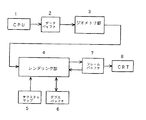
図1は、本発明のポリゴンによる画像形成方法を適用する画像処理装置の構成ブロック図である。
【0016】
図1において、CPU1は、ポリゴンにより表示される画像を処理するためのプログラムの実行を制御するものである。CPU1にはプログラムの進行に伴いディスプレー装置8上に表示するポリゴンの頂点データやレジスタセットファンクションを一次的に蓄えておくメモリであるデータバッファ2が接続されている。
【0017】
そして、このメモリに蓄えられる、ディスプレー装置8上に表示する地形画像モデルに対応するポリゴンの頂点データを簡易に生成することに本発明の特徴がある。図1において、前記頂点データに従って3次元空間内にポリゴンを配置し、これをディスプレー装置8上に表示するために2次元座標系に変換するためのジオメトリ処理部3が、データバッファ2に接続されている。
【0018】
更に、表示する各ポリゴンに対し、着色、シェーディング、テクスタチャの貼り付けを行うレンダリング処理部4が接続されている。レンダリング処理部4の出力側には、フレームバッファ7が接続され、表示される一画面分のデータが格納される。フレームバッファ7にCRT等のディスプレー装置8が接続され、フレームバッファ7の内容が順次に表示される。
【0019】
ここで、上記ジオメトリ処理部3は、データバッファ2からプログラムの進行及び処理速度に対応して、ポリゴンの頂点データ(頂点座標、頂点カラー、テクスチャマップ座標、頂点透明度及び頂点の法線ベクトル等を有する)やレジスタセットファンクションを読み出す。
【0020】
ジオメトリ処理部3は、頂点座標データに基づき3次元空間にポリゴンを配置し、3次元空間のどの領域まで表示対象とするかのビューポートの決定、法線ベクトルに基づき各頂点の輝度の計算等を行う。また、ビューポートよりはみ出すポリゴンの頂点除去即ち、クリッピングを行う。更に、ビューポートに配置されたポリゴンを所定の視点を基準に2次平面に投影して3次元から2次元への座標変換を行う。
【0021】
2次元座標に座標変換されたポリゴンデータは、レンダリング処理部4に送られる。レンダリング処理部4は、図示しない塗り潰し回路、テクスチャ貼り付け回路、デプステスト回路、ブレンディング回路から構成されている。
【0022】
塗り潰し回路は、ポリゴンの各頂点で囲まれた範囲にある画素(ピクセル)の情報を計算し、他のレンダリング処理部4内の各回路に渡す機能を有する。上記計算は、ポリゴンの各頂点間にあるピクセルの情報を対応の両頂点に与えられている頂点情報(頂点座標、頂点輝度、頂点カラー等)を基に、例えば線形補間するものである。
【0023】
テクスチャ貼り付け回路は、ピクセルの座標に対応したアドレス位置にあるテクスチャをテクスチャマップ5から読み出し、ピクセルのカラーを計算して求める回路である。デプステスト回路は、複数のポリゴンの前後関係を比較して、最も手前に配置されたポリゴンのデータをデプスバッファ6に記憶させる回路である。
【0024】
即ち、デプスバッファ6には、先に描いた図形(ポリゴン)のピクセルのZ値が記憶されている。特に、本発明に従い生成されるポリゴンデータを考えると、後に生成過程を説明するように、多面体の実施例として直方体を考えると、直方体の回転により隣接する直方体の面同士が交差する場合が生じる。
【0025】
したがって、直方体の面の一部が隣接する直方体の面に入り込み、隣接する直方体の面に隠されることになる。かかる場合は、隣接する直方体の面に隠される部分は表示されない。この隠される部分は、デプス値が隣接する直方体の面のそれより大きく、奥側にあることになる。
【0026】
このようにポリゴン同士のデプス値を比較し、比較の時点で手前に位置するポリゴンを表示対象とすべく、該当のポリゴンデータをデプスバッファ6に記憶させる。
【0027】
そして、画面上の先に描かれたポリゴンと重なる位置に、新しくポリゴンを表示する場合、新しいポリゴンを構成する各ピクセルのZ値と、デプスバッファ6から読み出される先に描かれたポリゴンのピクセルのZ値とを比較する。比較の結果、新しいポリゴンのピクセルが手前の場合は、デプスバッファ6に当該ピクセルのZ値が書き込まれる。
【0028】
ブレンディング回路は、フレームバッファ7から読み込んだ、先に描かれているポリゴンのピクセルのカラー情報と、新しく処理するポリゴンのピクセルのカラー情報とを混合し、フレームバッファ7に再び書き込む。このフレームバッファ7の情報が1画面分ずつディスプレー装置8に送られて表示される。
【0029】
次に、上記のような構成の画像処理装置において、画像表示のために処理されるポリゴンによる画像モデルのデータを本発明に従い形成する実施の形態を説明する。
【0030】
以下の実施の形態の説明において、画像モデルを地形画像を例として説明するが、本発明はかかる画像モデルに限定されない。海面画像、樹木肌の画像等の表示にも適用可能である。
【0031】
図2は、ポリゴンによる地形画像データの本発明に従う形成方法の実施の形態処理フローである。本発明の説明において、基準となる物体をオブジェクトと呼ぶ。そして、オブジェクトの実施例として直方体を仮想3次元空間内に想定する(ステップS1)。このオブジェクトは、8個の頂点と6つの面を有する。従って、8個の各頂点に対する3次元座標データが特定される。
【0032】
次いで、 このオブジェクトを3次元座標の2軸方向の2次元平面に平行移動して複数個並べる(ステップS2)。これは、仮想3次元空間内に想定された前記直方体の2軸方向の座標値を順次シフトすることにより平行移動し、複数の直方体を平面状に並べることが可能である。この時、平面状に並べられた複数の直方体の隣接する直方体同士が重なる様に配置される。
【0033】
かかる様子は、図3のように示される。即ち、図3において、仮想3次元空間内に前記直方体10が想定される。そして、この直方体10をx、z軸座標方向に平行移動することにより、x、z軸方向の2次元平面100に複数個の直方体が並べられる。
【0034】
図3において、x、z軸方向の2次元平面100に複数個の直方体が並べられた状態において、参照数字101、102は、隣接する直方体同士の重なる部分の一例である。
【0035】
次いで、図2のフローに戻り説明すると、x、z軸方向の2次元平面100に並べられた複数個の直方体をそれぞれ回転させる(ステップS3)。好ましくは、Y軸に辺が平行とならない様に回転させる。これにより、x、z軸方向の2次元平面100に並べられた複数個の直方体の頂点のY軸方向の位置が同一とならず、高さが異なってくる。
【0036】
更に、このようにして形成される図形の表面に現れる直方体の各面の部分をポリゴンデータとし、これらのポリゴンデータを図1のデータバッファ2を通して、ジオメトリ部3、レンダリング部4により、先に説明したコンピュータグラフィック処理を行うことにより、図4に示す表示画面例のごとく地形の画像がディスプレー装置8に表示される。
【0037】
次に本発明のより良い理解のために、具体的実施例により、本発明を説明する。図5は、オブジェクトとして、直方体を立方体とした例である。従って、立方体は、8つの頂点▲1▼〜▲8▼と、6つの面を有して構成される。
【0038】
各頂点▲1▼〜▲8▼の座標データは、オブジェクトの中心を原点とした座標系、これをオブジェクト座標系と呼び、(x,y,z)で表わされる値とする。更に面データ(図5の例では、正方形)は、面を構成する4頂点の番号例えば、(p▲1▼、p▲2▼、p▲3▼、p▲4▼)で表わされる。
【0039】
更に、図6は、かかる図5のオブジェクトを基に、図2の手順を実行する過程を示す図であり、実施例として、x−z軸の2次元平面にオブジェクトを4つ並べる場合の例を示す図である。図6の(a)列は、上面から見た図、図6の(b)列は、斜めから観察した時の図である。
【0040】
上記図5のオブジェクトをx軸方向、z軸方向に平行移動して(縦2×横2)個となるように並べる[図6(1)〜(3)参照]。この時、それぞれ隣接するオブジェクトが重なるように並べる。
【0041】
今、x軸方向、z軸方向への平行移動量をそれぞれMx、Mzとした時、オブジェクトの1頂点(x,y,z)の平行移動後の座標は、(x+Mx,y,z+Mz)となる。尚、平行移動量Mx、Mzは、同一オブジェクト内のすべての頂点について同じである。
【0042】
このようにして、オブジェクトをx軸方向、z軸方向に平行移動して縦2×横2個とした時の地形モデルは、頂点データの数8×4=32個、面データの数6×4=24個で構成される。
【0043】
次いで、並べられたオブジェクトを回転させる(図6(4)〜(5)参照)。各オブジェクトをオブジェクト座標のx,y,z軸に対し、任意の角度で回転させる。回転は、各オブジェクトごとに行う。
【0044】
オブジェクトのx軸回転の角度をRxとした時、オブジェクト内の点の座標(x,y,z)のx軸回転後の座標は、
(x,y×cosRx +z×sinRx ,−y× sinRx +z× cosRx )
となる。
【0045】
同様に、y軸回転の角度をRyとすると、y軸回転後の座標は、
(x×cosRy −z× sinRy ,y,x× sinRy +z× cosRy )
となる。更に、
同様に、z軸回転の角度をRzとすると、z軸回転後の座標は、
(x× cosRz +y× sinRz ,−x× sinRz +y× cosRz,z)
となる。
【0046】
更に、複数の軸に対して回転を行う場合は、上記の関係に従って、それぞれの回転を順番に行えばよい。なお、Rx,Ry,Rzは同一のオブジェクト内の全ての点で一定である。
【0047】
図7は、上記のようにして生成したモデルを上面から見た図である。○で囲んだ部分の頂点は、オブジェクトが重なりあって、生じたものであり、頂点データは存在しない。これに対し、かかる頂点を含む全ての頂点についてデータが必要であった従来の方法と比較して、本発明によりデータ量を増加させない利点が容易に理解できる。
【0048】
ここで、一般にコンピュータグラフィック技術において、オブジェクトを構成するポリゴンを、3角形または4角形とする場合が一般的である。したがって、地形モデルを構成する面は、図7に示されるように、4角形に限られないが3角形及び4角形以外の多角形である場合は、複数の3角形及び/または4角形に切り分けて別々に面データとして持つ必要がある。
【0049】
このため、従来の方法では、頂点データが更に増加することになるが、本発明によりかかる頂点データが増加するという問題も回避できる。
【0050】
図8は、更に本発明の拡張の実施の形態である。図6(3)のように平面に並べられた複数のオブジェクトを、回転する前に、y軸方向に任意に平行移動するようにしている(図8(a)参照)。
【0051】
従って、y軸方向に任意に平行移動した後、図6(4),(5)で説明したように、オブジェクトを回転することにより、図8(b)に示すように、より複雑なモデルを形成することが可能である。
【0052】
更に、上記した実施の形態および実施例において、オブジェクトをx軸、z軸に平行移動する際に、隣接するオブジェクトを重ねるように説明した。これによりオブジェクトが重なりあい、複雑な形状を容易に作ることが可能である。更に、隣接するオブジェクトを重ねる様に平行移動する理由は、オブジェクトが重なりあっていないと、オブジェクトを回転させた時にオブジェクトとオブジェクトの間に隙間が生じるのを防ぐためである。
【0053】
しかし、より簡易に複雑な形状を生成する場合は、必ずしも隣接するオブジェクトを重ねる様に平行移動する必要はない。更に、本発明は、基本となるオブジェクトは直方体に限定されない。直方体に対し、3角錐となる4面体あるいは、6面より大きい多面体を用いることも可能である。
【0054】
この場合は、オブジェクトを並べた時及び、回転させた時に、オブジェクト間に隙間が生じる可能性がある。従って、オブジェクト間の隙間を例えばオブジェクトを構成するポリゴンのテキスチャデータの平均値で埋めるようにすることも可能である。
【0055】
図9は、オブジェクトを並べた時及び、回転させた時に、オブジェクト間に隙間が生じる可能性に対する別の対応を説明する図であり、多面体として3角錐を用いた例である。
【0056】
図9において、3角錐100が先に直方体の例で説明した同様に並べられ、且つ回転された状態を示している。3角錐100は、4面のポリゴン面で構成され5つの頂点座標を有する。したがって、3角錐100の配置及び回転状態により5つの頂点座標が変化するだけで、ポリゴンによる画像が形成できる。
【0057】
更に、図9では、並べられた複数の3角錐100の間に隙間104が生じている。したがって、所定の隙間埋め込み用のポリゴン10を用意する。図9において3角錐100の下部の波線部分101,102,103は、画像表示領域を設定するクリッピングの段階で隙間埋め込み用のポリゴン10の下側部分に位置され非表示部分となる3角錐100のポリゴン領域部分である。
【0058】
ポリゴン10に対し所定のテキスチャデータが与えられるので、複数の3角錐100の間に生じた隙間104は、ポリゴン10に対する所定のテキスチャデータで埋め込まれる。この時、ポリゴン10に対する所定のテキスチャデータを3角錐100を構成するポリゴンのテキスチャデータと同一又は、類似とすることにより複数の3角錐100とポリゴン10との連続性が保つことができる。
【0059】
尚、隙間埋め込み用のポリゴン10の頂点座標A,B,C,Dは、例えば画像表示領域を設定する上記のクリッピングの段階でのクリッピング面と垂直になるように設定すれば良い。
【0060】
又、図9の例において、隙間埋め込み用のポリゴン10を1つのみ示しているが、簡単化を阻害しない限りであれば、複数枚の隙間埋め込み用のポリゴンを所定角度で交差させて用いることも可能である。
【0061】
【発明の効果】
以上、図面に従い実施の形態を説明したように、本発明は、オブジェクトを平行移動、回転する処理も頂点ごとに行うことなく、オブジェクト単位で行うことが可能である。このため、処理の手順を少なく行える。
【0062】
更に、本発明を適用することにより、地形、水面、木面等のオブジェクトをポリゴンにより形成する場合に簡易な操作で、しかも少ないデータ量で形成することが可能である。
【図面の簡単な説明】
【図1】本発明のポリゴンによる地形画像形成方法を適用する画像処理装置の構成ブロック図である。
【図2】ポリゴンによる地形画像データの本発明に従う形成方法の実施の形態処理フローである。
【図3】本発明の方法において、オブジェクトを3次元座標の2軸方向の2次元平面に複数個並べる過程を説明する図である。
【図4】地形の画像をディスプレーに表示されタイムチャート時の状態例を示す図である。
【図5】オブジェクトとして、直方体を立方体とした例を示す図である。
【図6】図5のオブジェクトを基に、図2の手順を実行する過程を示す図であり、実施例として、x−z軸の2次元平面にオブジェクトを4つ並べる場合の例を示す図である。
【図7】本発明に従い生成したモデルを上面から見た状態を説明する図である。
【図8】本発明の拡張の実施の形態であり、オブジェクトをy軸方向に更に平行移動する様子を説明する図である。
【図9】オブジェクト間に隙間が生じる時の対応を説明する図である。
【図10】ポリゴンで表示される複雑な地形の一例を示す図である。
【符号の説明】
1 CPU
2 データバッファ
3 ジオメトリ処理部
4 レンダリング処理部
5 テクスチャマップ
6 デプスバッファ
7 フレームバッファ
8 ディスプレー[0001]
BACKGROUND OF THE INVENTION
The present invention relates to a method for forming an image model such as terrain using polygons and an image processing apparatus using the method, and more particularly to a method for forming an image model using polygons based on vertex data of one polyhedron and the method. The present invention relates to an image processing apparatus.
[0002]
[Prior art]
In recent years, image processing apparatuses that display images of objects arranged in a virtual three-dimensional space using computer graphic technology have become widespread, and research and development of virtual reality has been promoted in order to display display objects closer to reality. ing.
[0003]
In such computer graphic technology, an object in a virtual three-dimensional space is displayed by being composed of a plurality of polygonal surfaces, so-called polygons. Further, an image model such as complicated terrain is displayed with a plurality of polygons.
[0004]
FIG. 10 is a diagram illustrating a topographic image as an example of a complex image model displayed with polygons. Three-dimensional coordinates are given to the vertices of a plurality of polygons constituting the terrain to form terrain image data. For example, the polygon A has vertices a1, a2, and a3, and the polygon B has vertices b1 (= a2), b2, b3, and b4. Further, the polygon C has vertices c1 (= b3), c2, c3, and c4, and the polygon D has vertices d1 (= b4), d2 (= c1), d3 (= c4), and d4.
[0005]
Therefore, as the image model such as terrain becomes more complex, the number of polygons increases, and the vertex coordinate data of each polygon becomes enormous. For this reason, when displaying the state of the sea surface and the undulations of the ground surface, etc., where the fineness is not necessarily required for the display image, the data for image formation increases and the design takes a considerable time.
[0006]
[Problems to be solved by the invention]
Accordingly, it is an object of the present invention to provide an image forming method using polygons and an image processing apparatus using the method, which can form an image model with a simple procedure.
[0007]
Further, an object of the present invention is to provide an image forming method using polygons and an image processing apparatus using this method that can form a complex image model by repeatedly preparing only predetermined vertex data and transforming it. It is to provide.
[0008]
[Means for Solving the Problems]
In order to achieve the above object, as a basic configuration of an image forming method using polygons according to the present invention, three-dimensional coordinate data is assigned to each vertex of one polyhedron in a virtual three-dimensional space in an image forming method using polygon data. Identifying and translating coordinate data corresponding to a two-dimensional plane formed by two orthogonal axes among the three-dimensional coordinate data specified for each vertex, and arranging a plurality of polyhedra on the two-dimensional plane; Each of the arranged polyhedrons is rotated by a predetermined angle so that an image model is represented by a plurality of polygons appearing on the surface.
[0009]
Furthermore, the gap generated in the plurality of polyhedrons arranged in the two-dimensional plane is filled with texture data having values obtained from the texture data for each surface of the polyhedron, if necessary.
[0010]
In this case, the texture data of values obtained from the texture data for each surface of the polyhedron can be easily set to the average value of the texture data for each surface of the polyhedron.
[0011]
Further, when the polyhedron is a rectangular parallelepiped, three-dimensional coordinate data is specified for each vertex of one rectangular parallelepiped in the virtual three-dimensional space, and two orthogonal axes among the three-dimensional coordinate data specified for each vertex. The coordinate data corresponding to the two-dimensional plane formed by the above are translated, and adjacent to each other so that at least some of them overlap each other, a plurality of rectangular parallelepipeds are sequentially arranged on the two-dimensional plane, and the arranged Each of the plurality of rectangular parallelepipeds is rotated by a predetermined angle, and an image model is represented by a plurality of polygons appearing on the surface.
[0012]
In this way, by arranging a plurality of rectangular parallelepipeds on a two-dimensional plane based on the three-dimensional coordinate data of each vertex of a polyhedron, typically a rectangular parallelepiped, and rotating them, it is easy with less data and simple processing. An image model using polygons can be formed.
[0013]
Furthermore, the arbitrary rectangular parallelepipeds arranged in order adjacent to each other are shifted in a third axial direction perpendicular to the two orthogonal axes, and then each of the plurality of rectangular parallelepipeds is rotated by a predetermined angle. Like that. Thereby, a more complicated image model can be easily formed.
[0014]
DETAILED DESCRIPTION OF THE INVENTION
Embodiments of the present invention will be described below with reference to the drawings. In the drawings, the same or similar elements are denoted by the same reference numerals or reference symbols.
[0015]
FIG. 1 is a block diagram showing the configuration of an image processing apparatus to which an image forming method using polygons according to the present invention is applied.
[0016]
In FIG. 1, a
[0017]
The feature of the present invention is that the vertex data of the polygon corresponding to the terrain image model displayed on the
[0018]
Further, a
[0019]
Here, the
[0020]
The
[0021]
The polygon data coordinate-converted into two-dimensional coordinates is sent to the
[0022]
The filling circuit has a function of calculating information of pixels (pixels) in a range surrounded by the vertices of the polygon and passing the information to each circuit in the other
[0023]
The texture pasting circuit is a circuit that reads out the texture at the address position corresponding to the coordinates of the pixel from the
[0024]
That is, the
[0025]
Therefore, a part of the surface of the rectangular parallelepiped enters the surface of the adjacent rectangular parallelepiped and is hidden by the surface of the adjacent rectangular parallelepiped. In such a case, a portion hidden by the adjacent rectangular parallelepiped surface is not displayed. This hidden portion has a depth value larger than that of the adjacent rectangular parallelepiped surface and is on the far side.
[0026]
In this way, the depth values of the polygons are compared, and the corresponding polygon data is stored in the
[0027]
When a new polygon is displayed at a position overlapping with the previously drawn polygon on the screen, the Z value of each pixel constituting the new polygon and the pixel of the previously drawn polygon read from the
[0028]
The blending circuit mixes the color information of the previously drawn polygon pixel read from the
[0029]
Next, an embodiment in which image model data by polygons processed for image display is formed according to the present invention in the image processing apparatus configured as described above will be described.
[0030]
In the following description of the embodiments, an image model will be described by taking a terrain image as an example, but the present invention is not limited to such an image model. The present invention can also be applied to display of a sea surface image, a tree skin image, and the like.
[0031]
FIG. 2 is a processing flow of an embodiment of a method for forming terrain image data by polygons according to the present invention. In the description of the present invention, a reference object is called an object. A rectangular parallelepiped is assumed in the virtual three-dimensional space as an example of the object (step S1). This object has 8 vertices and 6 faces. Accordingly, the three-dimensional coordinate data for each of the eight vertices is specified.
[0032]
Next, a plurality of these objects are translated and arranged on the two-dimensional plane in the two-axis direction of the three-dimensional coordinates (step S2). This is possible by parallel shifting by sequentially shifting the coordinate values in the biaxial direction of the rectangular parallelepiped assumed in the virtual three-dimensional space, and arranging a plurality of rectangular parallelepipeds in a planar shape. At this time, the adjacent rectangular parallelepipeds of a plurality of rectangular parallelepipeds arranged in a plane are arranged so as to overlap each other.
[0033]
Such a situation is shown in FIG. That is, in FIG. 3, the
[0034]
In FIG. 3, in the state where a plurality of rectangular parallelepipeds are arranged on the two-
[0035]
Next, returning to the flow of FIG. 2, a plurality of rectangular parallelepipeds arranged on the two-
[0036]
Further, the portion of each surface of the rectangular parallelepiped that appears on the surface of the figure formed in this way is set as polygon data, and these polygon data are explained by the
[0037]
Next, for better understanding of the present invention, the present invention will be described by way of specific examples. FIG. 5 shows an example in which a rectangular parallelepiped is used as the object. Therefore, the cube has eight vertices (1) to (8) and six faces.
[0038]
The coordinate data of the vertices (1) to (8) is a coordinate system with the center of the object as the origin, called the object coordinate system, and is a value represented by (x, y, z). Further, the surface data (square in the example of FIG. 5) is represented by the numbers of the four vertices constituting the surface, for example, (
[0039]
Further, FIG. 6 is a diagram showing a process of executing the procedure of FIG. 2 based on the object of FIG. 5, and as an example, an example in which four objects are arranged on a two-dimensional plane of the xz axis. FIG. The row (a) in FIG. 6 is a view seen from above, and the row (b) in FIG. 6 is a view when observed from an oblique direction.
[0040]
The objects shown in FIG. 5 are translated in the x-axis direction and the z-axis direction (2 × 2 in the vertical direction) so as to be arranged [see FIGS. 6 (1) to (3)]. At this time, the adjacent objects are arranged so as to overlap each other.
[0041]
Now, when the translation amounts in the x-axis direction and the z-axis direction are Mx and Mz, respectively, the coordinates after translation of one vertex (x, y, z) of the object are (x + Mx, y, z + Mz). Become. The parallel movement amounts Mx and Mz are the same for all vertices in the same object.
[0042]
In this way, when the object is translated in the x-axis direction and the z-axis direction to be 2 × 2 vertically, the number of vertex data is 8 × 4 = 32 and the number of surface data is 6 ×. 4 = 24.
[0043]
Next, the arranged objects are rotated (see FIGS. 6 (4) to (5)). Each object is rotated at an arbitrary angle with respect to the x, y, and z axes of the object coordinates. The rotation is performed for each object.
[0044]
When the x-axis rotation angle of the object is Rx, the coordinates of the coordinates (x, y, z) of the point in the object after the x-axis rotation are
(X, y x cosRx + z x sinRx, -y x sinRx + z x cosRx)
It becomes.
[0045]
Similarly, if the angle of y-axis rotation is Ry, the coordinates after y-axis rotation are
(X × cosRy−z × sinRy, y, x × sinRy + z × cosRy)
It becomes. In addition,
Similarly, if the angle of z-axis rotation is Rz, the coordinates after z-axis rotation are
(X x cosRz + y x sinRz, -x x sinRz + y x cosRz, z)
It becomes.
[0046]
Furthermore, when rotating about a some axis | shaft, what is necessary is just to perform each rotation in order according to said relationship. Rx, Ry, and Rz are constant at all points in the same object.
[0047]
FIG. 7 is a view of the model generated as described above as viewed from above. The vertices surrounded by ○ are generated by overlapping objects, and there is no vertex data. On the other hand, the advantage of not increasing the amount of data according to the present invention can be easily understood as compared with the conventional method that requires data for all vertices including such vertices.
[0048]
Here, in general, in a computer graphic technique, a polygon constituting an object is generally a triangle or a quadrangle. Therefore, as shown in FIG. 7, the surface constituting the terrain model is not limited to a quadrangular shape, but when it is a polygon other than a triangular shape and a quadrangular shape, it is divided into a plurality of triangular shapes and / or quadrangular shapes. It is necessary to have as plane data separately.
[0049]
For this reason, in the conventional method, the vertex data is further increased, but the problem that the vertex data is increased according to the present invention can also be avoided.
[0050]
FIG. 8 is a further embodiment of the expansion of the present invention. A plurality of objects arranged in a plane as shown in FIG. 6 (3) are arbitrarily translated in the y-axis direction before rotating (see FIG. 8 (a)).
[0051]
Accordingly, after arbitrary translation in the y-axis direction, as described in FIGS. 6 (4) and (5), by rotating the object, a more complex model can be obtained as shown in FIG. 8 (b). It is possible to form.
[0052]
Furthermore, in the above-described embodiments and examples, it has been described that adjacent objects are overlapped when the object is translated along the x-axis and the z-axis. As a result, the objects overlap and it is possible to easily create a complicated shape. Further, the reason why the adjacent objects are translated so as to overlap each other is to prevent a gap from being generated between the objects when the objects are not rotated.
[0053]
However, when a complicated shape is generated more easily, it is not always necessary to translate the adjacent objects so as to overlap each other. Furthermore, in the present invention, the basic object is not limited to a rectangular parallelepiped. It is also possible to use a tetrahedron that is a triangular pyramid or a polyhedron that is larger than six sides with respect to a rectangular parallelepiped.
[0054]
In this case, a gap may be generated between the objects when the objects are arranged and rotated. Accordingly, it is also possible to fill the gaps between the objects with, for example, the average value of the texture data of the polygons constituting the objects.
[0055]
FIG. 9 is a diagram for explaining another response to the possibility of a gap between objects when objects are arranged and rotated, and is an example using a triangular pyramid as a polyhedron.
[0056]
FIG. 9 shows a state in which the
[0057]
Further, in FIG. 9, a
[0058]
Since predetermined texture data is given to the
[0059]
The vertex coordinates A, B, C, and D of the gap-filling
[0060]
In the example of FIG. 9, only one
[0061]
【The invention's effect】
As described above with reference to the drawings, according to the present invention, it is possible to perform the process of translating and rotating an object in units of objects without performing the process for each vertex. For this reason, the number of processing steps can be reduced.
[0062]
Furthermore, by applying the present invention, it is possible to form an object such as a topography, a water surface, a tree surface, etc. with polygons with a simple operation and a small amount of data.
[Brief description of the drawings]
FIG. 1 is a block diagram showing a configuration of an image processing apparatus to which a terrain image forming method using polygons according to the present invention is applied.
FIG. 2 is a processing flow of an embodiment of a method for forming terrain image data by polygons according to the present invention;
FIG. 3 is a diagram illustrating a process of arranging a plurality of objects on a two-dimensional plane in a two-axis direction of three-dimensional coordinates in the method of the present invention.
FIG. 4 is a diagram showing an example of a state when a topographic image is displayed on a display and is a time chart.
FIG. 5 is a diagram illustrating an example in which a cuboid is a cube as an object;
6 is a diagram illustrating a process of executing the procedure of FIG. 2 based on the object of FIG. 5, and illustrates an example of arranging four objects on a two-dimensional plane of an xz axis as an example. It is.
FIG. 7 is a diagram illustrating a state where a model generated according to the present invention is viewed from above.
FIG. 8 is a diagram for explaining how the object is further translated in the y-axis direction according to an embodiment of the extension of the present invention.
FIG. 9 is a diagram illustrating a response when a gap is generated between objects.
FIG. 10 is a diagram illustrating an example of complex terrain displayed with polygons.
[Explanation of symbols]
1 CPU
2
Claims (4)
ジオメトリ処理部により ,
各頂点に三次元座標データが特定された複数のポリゴンにより形成される多面体を,仮想三次元空間内の直交する2軸X , Zにより形成される二次元平面に平面状に複数個並べるステップと,
前記平面状に複数個並べられた前記複数の多面体のそれぞれを,前記多面体内の点の座標の3軸方向X,Y,Zに対してそれぞれRx,Ry,Rzの角度で回転させるステップと,
前記回転された複数の多面体により形成されるモデルを,前記仮想三次元空間内の視点を基準に二次元平面に投影して二次元座標データに変換するステップを有し,
さらに,レンダリング処理部により,
前記二次元平面に投影された二次元座標データに地形のテクスチャを貼り付けるレンダリング処理を行うステップと,
を有することを特徴とするポリゴンデータによる地形画像の形成方法。 In accordance with a program executed by the image processing apparatus, a method of forming a more terrain image into polygon data,
The geometry processing unit,
The polyhedron three-dimensional coordinate data on each vertex is formed by a plurality of polygons are specified, two orthogonal axes X in the virtual three-dimensional space, and a plurality pieces arranged step in a plane in a two dimensional plane formed by the Z ,
And rotating each of the plurality of polyhedrons which are arranged a plurality of said planar, three axial directions X coordinate of a point in said polyhedron, Y, respectively Rx, Ry, at an angle of Rz relative Z,
Comprising the step of converting said rotated plurality of models formed by polyhedron, projected to the two-dimensional coordinate data in a two-dimensional plane based on the viewpoint of the virtual three-dimensional space,
In addition, the rendering processor
Performing a rendering process of pasting a terrain texture on the two-dimensional coordinate data projected onto the two-dimensional plane ;
Method of forming a topographical image by polygon data, characterized in that it comprises a.
前記ジオメトリ処理部による多面体を複数に並べるステップにおいて,少なくとも一部が相互に重なるように隣接して,前記二次元平面に並べられることを特徴とするポリゴンデータによる地形画像の形成方法。 According to claim 1,
A method for forming a topographic image using polygon data , wherein, in the step of arranging a plurality of polyhedrons by the geometry processing unit , at least a part thereof is arranged adjacent to each other so as to overlap each other.
更に,前記ジオメトリ処理部により ,前記二次元平面に並べられた複数個の多面体に生じる隙間を,所定のテクスチャデータが与えられた隙間埋め込み用ポリゴンを埋め込むステップを有することを特徴とするポリゴンデータによる地形画像の形成方法。 According to claim 1,
Further, by the geometry processing section, a gap generated plurality of polyhedron arranged in the two-dimensional plane, by the polygon data, characterized by comprising the step of embedding polygon for implantation gap predetermined texture data is given the method of forming the terrain image.
前記プログラムは,
前記CPUに ,
ジオメトリ処理部により ,
前記ポリゴンの各頂点に三次元座標データが特定された多面体を,仮想三次元空間内の直交する2軸X,Yにより形成される二次元平面に平面状に複数並べさせ,更に,並べられた前記複数の多面体のそれぞれを,該多面体内の点の座標の3軸方向X,Y,Zに対してそれぞれRx,Ry,Rzの角度で回転させるステップと,
前記回転された複数の多面体により形成されるモデルを,前記仮想三次元空間内の視点を基準に2次元平面に投影して二次元座標データに変換させるステップと,
さらに,レンダリング処理部により,
前記二次元座標データに地形のテクスチャを貼り付けるレンダリング処理を行うステップと,
を実行制御させることを特徴とするプログラムを格納した記録媒体。A CPU that controls execution of a program, and a recording that stores a program for converting a polyhedron in which 3D coordinate data is specified at each vertex of the polygon into 2D coordinate data by executing execution control of the program by the CPU. A medium,
The program is
To the CPU,
The geometry processing unit,
A plurality of polyhedrons in which three-dimensional coordinate data is specified at each vertex of the polygon are arranged in a plane on a two-dimensional plane formed by two orthogonal axes X and Y in a virtual three-dimensional space, and further arranged. a step of each of the plurality of polyhedrons, each Rx, Ry, Ru is rotated at an angle of Rz 3 axial direction X of the coordinates of the points of the multi surface body, Y, with respect to Z,
A step of said rotated plurality of models formed by polyhedron, Ru is converted by projecting a two-dimensional plane based on the viewpoint of the virtual three-dimensional space into a two-dimensional coordinate data,
In addition, the rendering processor
Performing a rendering processing a texture of the terrain to the two-dimensional coordinate data,
A recording medium storing a program characterized in that execution control is performed .
Priority Applications (1)
| Application Number | Priority Date | Filing Date | Title |
|---|---|---|---|
| JP8854097A JP3931375B2 (en) | 1997-04-07 | 1997-04-07 | Image forming method using polygon and image processing apparatus using this method |
Applications Claiming Priority (1)
| Application Number | Priority Date | Filing Date | Title |
|---|---|---|---|
| JP8854097A JP3931375B2 (en) | 1997-04-07 | 1997-04-07 | Image forming method using polygon and image processing apparatus using this method |
Publications (2)
| Publication Number | Publication Date |
|---|---|
| JPH10283500A JPH10283500A (en) | 1998-10-23 |
| JP3931375B2 true JP3931375B2 (en) | 2007-06-13 |
Family
ID=13945689
Family Applications (1)
| Application Number | Title | Priority Date | Filing Date |
|---|---|---|---|
| JP8854097A Expired - Fee Related JP3931375B2 (en) | 1997-04-07 | 1997-04-07 | Image forming method using polygon and image processing apparatus using this method |
Country Status (1)
| Country | Link |
|---|---|
| JP (1) | JP3931375B2 (en) |
Families Citing this family (2)
| Publication number | Priority date | Publication date | Assignee | Title |
|---|---|---|---|---|
| US7184051B1 (en) | 1999-09-10 | 2007-02-27 | Sony Computer Entertainment Inc. | Method of and apparatus for rendering an image simulating fluid motion, with recording medium and program therefor |
| JP3625172B2 (en) | 2000-04-26 | 2005-03-02 | コナミ株式会社 | Image creating apparatus, image creating method, computer-readable recording medium on which image creating program is recorded, and video game apparatus |
-
1997
- 1997-04-07 JP JP8854097A patent/JP3931375B2/en not_active Expired - Fee Related
Also Published As
| Publication number | Publication date |
|---|---|
| JPH10283500A (en) | 1998-10-23 |
Similar Documents
| Publication | Publication Date | Title |
|---|---|---|
| US7088362B2 (en) | Graphic computing apparatus | |
| US6333747B1 (en) | Image synthesizing system with texture mapping | |
| EP1547019B1 (en) | Method and apparatus for rendering threedimensional objects | |
| US7095419B2 (en) | Applying multiple texture maps to objects in three-dimensional imaging processes | |
| US5877769A (en) | Image processing apparatus and method | |
| EP2973423B1 (en) | System and method for display of a repeating texture stored in a texture atlas | |
| CN107248193A (en) | The method, system and device that two dimensional surface is switched over virtual reality scenario | |
| GB2295757A (en) | Three-dimensional simulator and image generating method | |
| JP3514947B2 (en) | Three-dimensional image processing apparatus and three-dimensional image processing method | |
| US20110175924A1 (en) | System and Method for Image-Based Rendering with Object Proxies | |
| EP1031946B1 (en) | Recording medium,Image processing method and unit with integrated shaping model data | |
| JP2000011204A (en) | Image processing method and recording medium with image processing program recorded thereon | |
| EP1312047B1 (en) | Apparatus and method for rendering antialiased image | |
| JPH09330423A (en) | Three-dimensional shape data transforming device | |
| JP2006235839A (en) | Image processor and image processing method | |
| JP3350473B2 (en) | Three-dimensional graphics drawing apparatus and method for performing occlusion culling | |
| JP3931375B2 (en) | Image forming method using polygon and image processing apparatus using this method | |
| US20020051016A1 (en) | Graphics drawing device of processing drawing data including rotation target object and non-rotation target object | |
| US7372461B2 (en) | Image processing apparatus and method of same | |
| JPH07282292A (en) | Texture mapping method and image processor | |
| JP4081304B2 (en) | Drawing processing program, storage medium storing drawing processing program, drawing processing apparatus, and drawing processing method | |
| Borshukov | New algorithms for modeling and rendering architecture from photographs | |
| JP4308367B2 (en) | 3D image generation apparatus and environment map generation method | |
| JP4056118B2 (en) | Image processing device | |
| JPH09231402A (en) | Bump mapping method and picture generating device |
Legal Events
| Date | Code | Title | Description |
|---|---|---|---|
| A521 | Written amendment |
Free format text: JAPANESE INTERMEDIATE CODE: A523 Effective date: 20040407 |
|
| A621 | Written request for application examination |
Free format text: JAPANESE INTERMEDIATE CODE: A621 Effective date: 20040407 |
|
| A131 | Notification of reasons for refusal |
Free format text: JAPANESE INTERMEDIATE CODE: A131 Effective date: 20061121 |
|
| A521 | Written amendment |
Free format text: JAPANESE INTERMEDIATE CODE: A523 Effective date: 20070117 |
|
| TRDD | Decision of grant or rejection written | ||
| A01 | Written decision to grant a patent or to grant a registration (utility model) |
Free format text: JAPANESE INTERMEDIATE CODE: A01 Effective date: 20070220 |
|
| A61 | First payment of annual fees (during grant procedure) |
Free format text: JAPANESE INTERMEDIATE CODE: A61 Effective date: 20070305 |
|
| R150 | Certificate of patent (=grant) or registration of utility model |
Free format text: JAPANESE INTERMEDIATE CODE: R150 |
|
| LAPS | Cancellation because of no payment of annual fees |