JP3930264B2 - Magnetic bearing control device - Google Patents
Magnetic bearing control device Download PDFInfo
- Publication number
- JP3930264B2 JP3930264B2 JP2001138622A JP2001138622A JP3930264B2 JP 3930264 B2 JP3930264 B2 JP 3930264B2 JP 2001138622 A JP2001138622 A JP 2001138622A JP 2001138622 A JP2001138622 A JP 2001138622A JP 3930264 B2 JP3930264 B2 JP 3930264B2
- Authority
- JP
- Japan
- Prior art keywords
- magnetic bearing
- current
- bias current
- circuit
- constant current
- Prior art date
- Legal status (The legal status is an assumption and is not a legal conclusion. Google has not performed a legal analysis and makes no representation as to the accuracy of the status listed.)
- Expired - Lifetime
Links
Images


Classifications
-
- F—MECHANICAL ENGINEERING; LIGHTING; HEATING; WEAPONS; BLASTING
- F16—ENGINEERING ELEMENTS AND UNITS; GENERAL MEASURES FOR PRODUCING AND MAINTAINING EFFECTIVE FUNCTIONING OF MACHINES OR INSTALLATIONS; THERMAL INSULATION IN GENERAL
- F16C—SHAFTS; FLEXIBLE SHAFTS; ELEMENTS OR CRANKSHAFT MECHANISMS; ROTARY BODIES OTHER THAN GEARING ELEMENTS; BEARINGS
- F16C2360/00—Engines or pumps
- F16C2360/44—Centrifugal pumps
- F16C2360/45—Turbo-molecular pumps
Description
【0001】
【発明の属する技術分野】
本発明は、電磁石の磁気吸引力を利用して回転軸等の被浮上体を非接触で浮上支持する磁気軸受を制御する磁気軸受制御装置に関し、特に磁気軸受を構成する一対或いは複数対の電磁石に供給するバイアス定電流を調整する磁気軸受制御装置に関するものである。
【0002】
【従来の技術】
磁気軸受は、回転軸等の被浮上体を非接触で支持できる軸受であることから、例えばターボ分子ポンプ等に用いて高速回転運動が可能となり、軸受の摩耗という問題が生ぜず、又潤滑油等を必要としないのでメンテナンスフリーである等の種々の特徴を有している。係る磁気軸受には、回転軸を半径方向に浮上位置制御するラジアル能動磁気軸受、回転軸を軸方向に浮上位置制御するアキシャル能動磁気軸受がある。これら従来の磁気軸受を用いた磁気軸受制御装置の一部分の構成例を図1に示す。
【0003】
図1において、1は回転軸等の被浮上体であり、該被浮上体1の浮上位置は、該被浮上体1に対向して配置された変位センサ4、4により検出され、センサ回路5により変位電気信号に変換され、位相補正回路6によりPID(比例・積分・微分)処理された後、定電流回路7a、7bに入力され、被浮上体1に対向して配置された一対の電磁石2、2の磁極コイル3P、3Nにその変位量のずれを修正する磁気吸引力PP、PNに相当する励磁電流となって供給され、被浮上体1は電磁石2と電磁石2の間に磁気浮上支持される。
【0004】
磁気軸受の電磁石2においては、一般的に磁気吸引力が磁極コイルに流れる電流の2乗に比例することが知られているので対向する電磁石2、2の磁極コイル3P、3Nにある一定のバイアス電流IBP、IBNを供給し、センサ回路5からの変位電気信号に対して電磁石2、2の磁気吸引力PP、PNが直線的に比例関係になるようにしている。
【0005】
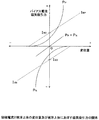
図2に示すように、変位量が中心点0より+方向、或いは−方向に変位した場合、対向する電磁石2、2の磁極コイル3P、3Nのそれぞれのバイアス電流IBP、IBNは増減し、結果として磁気吸引力PP、PNの合成の磁気吸引力はセンサ回路5からの変位電気信号に直線的に比例するようになる。また、変位量が0の場合のバイアス定電流IBOは、各回路構成における電気的な部品のばらつきや、被浮上体1の重量又は形状或いは電磁石2の構造の違いや、被浮上体1の浮上向きによって磁気軸受にその重力が加わる場合等において、良好な直線性が得られるようにバイアス電流調整器8、8等によってバイアス定電流IBOが調整されていた。
【0006】
上記のようなバイアス電流調整器8によるバイアス定電流調整方法は、磁気軸受の制御装置や被浮上体や磁気軸受構成が変わる異機種毎に手動で調整を行う必要があり、特に電磁石2の数が多い多軸制御の磁気軸受装置においてはその調整に多大な労力を要していた。更に、磁気軸受を用いたターボ分子ポンプ等の場合は、ポンプの取り付け姿勢に自由度が求められ、全ての取付姿勢において磁気軸受を構成する電磁石に良好なバイアス定電流を流すためには全ての電磁石に被浮上体の重量を考慮したバイアス定電流を供給する必要があり、結果として必要以上の電流が流れ、磁気軸受部の発熱やコントローラの大型化を招くという問題がある。
【0007】
【発明が解決しようとする課題】
本発明は上述の点に鑑みてなされたもので、同一のコントローラで異機種の磁気軸受装置及び磁気軸受装置の設置姿勢に対応して容易に磁気軸受を構成する電磁石のバイアス電流の調整ができ、且つ該バイアス電流値を必要最小の最適な状態に調整できる小型で、磁気軸受部の発熱量が少なくできる磁気軸受制御装置を提供することを目的とする。
【0012】
上記課題を解決するため請求項1に記載の発明は、被浮上体を磁気浮上支持する一対或いは複数対の電磁石、及び該被浮上体の浮上位置を検出する一対或いは複数対の変位センサを具備する単数又は複数の磁気軸受ユニットと、該電磁石に一定のバイアス電流を流して被浮上体を安定浮上制御させる定電流回路と、変位センサの出力信号に基いて浮上体を所定位置に浮上支持するように電磁石の励磁電流を制御する制御ループを具備する磁気軸受制御装置において、コントローラ、磁気軸受ユニットの一対或いは複数対の電磁石に流れるバイアス電流を検出する電流検出回路、定電流回路から供給されるバイアス電流を調整する定電流調整回路を設け、コントローラは該電流検出回路で検出したバイアス電流値が適正か否かを判断し、バイアス電流を予め決められた最適定電流値になるように定電流調整回路を介して調整する機能を具備することを特徴とする。
【0013】
上記のようにコントローラにより、電流検出回路で検出したバイアス電流値が適正か否かを判断し、バイアス電流を予め決められた最適電流値になるように定電流調整回路を介して調整するので、磁気軸受ユニットの電磁石のバイアス電流を最適定電流値に容易に調整することができる。また、バイアス電流値を磁気軸受ユニットの電磁石に流れるバイアス電流をフィードバックすることでバイアス電流値が目標値に達しているか否かを判断し自動調整するので、コントローラと磁気軸受装置の系に固体差があってもバイアス電流値を自動的に補正できるのである。
【0014】
請求項2に記載の発明は、被浮上体を磁気浮上支持する一対或いは複数対の電磁石、及び該被浮上体の浮上位置を検出する一対或いは複数対の変位センサを具備する単数又は複数の磁気軸受ユニットと、該電磁石に一定のバイアス電流を流して被浮上体を安定浮上制御させる定電流回路と、変位センサの出力信号に基いて浮上体を所定位置に浮上支持するように電磁石の励磁電流を制御する制御ループを具備する磁気軸受制御装置において、コントローラ、磁気軸受ユニットの一対或いは複数対の電磁石に流れるバイアス電流を検出する電流検出回路、定電流回路から供給されるバイアス電流を調整する定電流調整回路を設け、コントローラは各電流検出回路の検出電流値を読み込み、予め記憶された各磁気軸受ユニットの被浮上体の浮上向きにおける磁気軸受ユニットの各電磁石に流れるバイアス電流データと比較し、被浮上体の浮上向きを解析し、該解析結果に基いて各定電流回路からのバイアス電流が被浮上体の浮上している向きに対して予め定めた最適値になるように定電流調整回路を介して調整する機能を具備することを特徴とする。
【0015】
上記のようにコントローラにより、磁気軸受ユニットの被浮上体の浮上向きを解析し、該解析結果に基いて各定電流回路からのバイアス電流が被浮上体の浮上している向きに対して予め定めた最適値になるようにバイアス定電流を調整するので、例えば複数の磁気軸受ユニットを具備するターボ分子ポンプ等においてどのような取付姿勢であっても、電磁石に最適なバイアス電流を流すことができ、必要以上のバイアス電流による磁気軸受の発熱を防止できる。また、必要最小限のバイアス電流で制御可能なため、磁気軸受ユニットの電磁石の励磁に必要な電源容量も小さくできる。また、バイアス電流値を磁気軸受ユニットの電磁石に流れるバイアス電流をフィードバックし、予め記憶された各磁気軸受ユニットの被浮上体の浮上向きにおける電磁石に流れるバイアス電流データと比較し、被浮上体の浮上向きを解析し、該解析結果に基いて各定電流回路からのバイアス電流が被浮上体の浮上している向きに対して予め定めた最適値になるように調整するので、コントローラと磁気軸受装置の系に固体差があってもバイアス電流値を自動的に補正できる。
【0016】
請求項3に記載の発明は、請求項2に記載の磁気軸受制御装置において、制御ループを切断させるループ切断手段を設け、コントローラは磁気軸受ユニットの電磁石に流れる電流をバイアス電流のみに固定する機能を具備することを特徴とする。
【0017】
上記のようにコントローラが磁気軸受ユニットの電磁石に流れる電流をバイアス電流のみに固定する機能を具備するので、バイアス電流の調整が他の制御電流等に影響されることなくできるので、バイアス電流の調整が容易で且つ精度良くできる。
【0018】
請求項4に記載の発明は、請求項1乃至3のいずれか1項に記載の磁気軸受装置において、コントローラは前記定電流調整回路を介して調整したバイアス電流値を記憶する記憶装置を具備し、被浮上体の浮上制御に該記憶装置に記憶したバイアス電流値を利用することを特徴とする。
【0019】
上記のようにコントローラは記憶装置に記憶している定電流調整回路を介して調整したバイアス電流値を利用して被浮上体の浮上制御を行うので、一度バイアス電流の調整を行うと以後のバイアス電流の調整が不要或いは短縮できる。
【0020】
【発明の実施の形態】
以下、本発明の実施の形態例を図面に基いて説明する。図3は本発明に係る磁気軸受制御装置の構成例を示す図であり、本磁気軸受制御装置は、1軸方向の磁気軸受を制御する磁気軸受制御装置の構成例を示す。図3において、図1と同一符号を付した部分は同一又は相当部分を示す。図3において、9a、9bは定電流調整回路、10a、10bは電流検出回路、11は制御回路、12は不揮発性記憶装置(EEPROM)、13はアナログスイッチである。ここで、電磁石2、2と、変位センサ4、4で被浮上体1を磁気浮上させる磁気軸受ユニットを構成する。また、制御回路11と、不揮発性記憶装置12で制御コントローラを構成する。
【0021】
上記構成の磁気軸受制御装置において初期状態では、アナログスイッチ13は制御回路11により開き、制御ループを開放しており、制御回路11は不揮発性記憶装置12に記憶されている初期状態のバイアス定電流値を読み込み定電流調整回路9a、9bにその値を出力する。その後定電流調整回路9a、9bは定電流回路7a、7bを介して、電磁石2、2の磁極コイル3P、3Nに設定されたバイアス電流を供給する。この時アナログスイッチ13が制御ループを開放しているため、磁極コイル3P、3Nには定電流調整回路9a、9bにて設定されたバイアス電流のみが流れる。
【0022】
このバイアス電流を電流検出回路10a、10bにて検出し、その電流検出値を制御回路11に入力すると共に、制御回路11は不揮発性記憶装置12に予め設定記憶されている目標電流値との差を計算し、該目標電流値が磁極コイル3P、3Nに流れるように、定電流調整回路9a、9bに新たな指示値を出力する。電流検出回路10a、10bで検出した検出電流値が上記目標電流値と等しくなると、制御回路11はアナログスイッチ13を閉じ、制御ループを閉じる。これにより、電磁石2、2による被浮上体1の磁気浮上を開始する。
【0023】
変位センサ4及びセンサ回路5からの変位電気信号は位相補正回路6によりPID制御され、定電流回路7a、7bに入力され、被浮上体1の変位量に相当する励磁電流が磁極コイル3P、3Nに加減され被浮上体1を磁気浮上させるように制御が開始される。被浮上体1の磁気浮上後、該被浮上体1に軸重量が図のように加わった場合は、重量Mの力を相殺するために磁極コイル3Pに流れる励磁電流が増加し磁極コイル3Nに流れる励磁電流が減少する様に制御が行われる。その結果、電流検出回路10aと電流検出回路10bにて検出される電流値が異なり、この値を制御回路11が読み込むことで現在の被浮上体1の浮上方向、即ち磁気軸受ユニットの設置方向が判定できる。
【0024】
不揮発性記憶装置12には、上記初期状態のバイアス定電流値及び目標電流値の他に、被浮上体1の浮上方向(磁気軸受の設置方向)に対応する電磁石2へのバイアス定電流が記憶されており、制御回路11は不揮発性記憶装置12に記憶されている各浮上向きでのバイアス定電流値を参照し、電流検出回路10a、10bの電流検出値に合致する現在の浮上方向を探し出し、その浮上状態での最適のバイアス定電流値を不揮発性記憶装置12により再度読み込んで定電流調整回路9a、9bに新たな目標電流値となるバイアス定電流値を出力する。これにより磁極コイル3P、3Nに流れるバイアス電流は増減し、結果として電磁石2はセンサ変位電気信号に直線的に比例した磁気吸引力を発生することが可能となる。
【0025】
また、上記により最適に調整された時の定電流調整回路に対する補正値は、不揮発性記憶装置12に保存し、次回浮上時にこのデータを利用して前記の調整手順を短縮するようにしてもよい。
【0026】
図3に示す構成の磁気軸受制御装置は、1軸方向の磁気軸受を制御する場合であるが、1軸以上の複数の制御軸を備える磁気軸受装置に関しても同様に構成できる。図4は複数(図では3つ)の磁気軸受制御装置15の磁気軸受ユニット14のバイアス電流を1つの制御コントローラ16で調整する場合である。
【0027】
図4において、制御コントローラ16は制御回路11と不揮発性記憶装置(EEPROM)12で構成される。また、各磁気軸受制御装置15は定電流回路7a、7b、定電流調整回路9a、9b、電流検出回路10a、10b、アナログスイッチ13で構成される。また、各磁気軸受制御装置15にはそれぞれ磁気軸受ユニット14が接続されている。磁気軸受ユニット14は図示は省略するが図3に示すように、被浮上体1に対向して配置された一対の電磁石2、2、変位センサ4、4で構成される。
【0028】
そして電磁石2、2の磁極コイル3P、3Nは電流検出回路10a、10bを介して定電流回路7a、7bに接続され、変位センサ4、4の出力は図3に示すようにセンサ回路5に入力され、センサ回路5の出力は位相補正回路6に入力され、位相補正回路6の出力はアナログスイッチ13を介して定電流回路7a、7bに入力されるようになっている。バイアス定電流の調整方法は、図3の場合と同様であるからその説明は省略する。
【0029】
【発明の効果】
以上、説明したように各請求項の発明によれば、下記のような優れた効果が得られる。
【0032】
請求項1に記載の発明によれば、コントローラにより、電流検出回路で検出したバイアス電流値が適正か否かを判断し、バイアス電流を予め決められた最適電流値になるように定電流調整回路を介して調整するので、磁気軸受ユニットの電磁石のバイアス電流を最適定電流値に容易に調整することができる。また、バイアス電流値を磁気軸受ユニットの電磁石に流れるバイアス電流をフィードバックすることでバイアス電流値が目標値に達しているか否かを判断し自動調整するので、コントローラと磁気軸受装置の系に固体差があってもバイアス電流値を自動的に補正できるのである。
【0033】
請求項2に記載の発明によれば、コントローラにより、磁気軸受ユニットの被浮上体の浮上向きを解析し、該解析結果に基いて各定電流回路からのバイアス電流が被浮上体の浮上している向きに対して予め定めた最適値になるようにバイアス定電流を調整するので、例えば複数の磁気軸受ユニットを具備するターボ分子ポンプ等においてどのような取付姿勢であっても、電磁石に最適なバイアス電流を流すことができ、必要以上のバイアス電流による磁気軸受の発熱を防止できる。また、必要最小限のバイアス電流で制御可能なため、磁気軸受ユニットの電磁石の励磁に必要な電源容量も小さくできる。また、バイアス電流値を磁気軸受ユニットの電磁石に流れるバイアス電流をフィードバックし、予め記憶された各磁気軸受ユニットの被浮上体の浮上向きにおける電磁石に流れるバイアス電流データと比較し、被浮上体の浮上向きを解析し、該解析結果に基いて各定電流回路からのバイアス電流が被浮上体の浮上している向きに対して予め定めた最適値になるように調整するので、コントローラと磁気軸受装置の系に固体差があってもバイアス電流値を自動的に補正できる。
【0034】
請求項3に記載の発明によれば、コントローラが磁気軸受ユニットの電磁石に流れる電流をバイアス電流のみに固定する機能を具備するので、バイアス電流の調整が他の制御電流等に影響されることなくできるので、バイアス電流の調整が容易で且つ精度良くできる。
【0035】
請求項4に記載の発明によれば、コントローラは記憶装置に記憶している定電流調整回路を介して調整したバイアス電流値を利用して被浮上体の浮上制御を行うので、一度バイアス電流の調整を行うと以後のバイアス電流の調整が不要或いは短縮できる。
【図面の簡単な説明】
【図1】従来の磁気軸受制御装置の構成例を示す図である。
【図2】磁気軸受の磁極コイルに流れる励磁電流と被浮上体の変位量及び被浮上体に及ぼす磁気吸引力の関係を示す図である。
【図3】本発明に係る磁気軸受制御装置の構成例を示す図である。
【図4】本発明に係る磁気軸受制御装置の構成例を示す図である。
【符号の説明】
1 被浮上体
2 電磁石
3P、3N 磁極コイル
4 変位センサ
5 センサ回路
6 位相補正回路
7a、7b 定電流回路
8 バイアス電流調整器
9a、9b 定電流調整回路
10a、10b 電流検出回路
11 制御回路
12 不揮発性記憶装置
13 アナログスイッチ
14 磁気軸受ユニット
15 磁気軸受制御装置
16 制御コントローラ[0001]
BACKGROUND OF THE INVENTION
The present invention relates to a magnetic bearing control device that controls a magnetic bearing that floats and supports a floating body such as a rotating shaft in a non-contact manner by using a magnetic attraction force of an electromagnet, and in particular, a pair or a plurality of pairs of electromagnets constituting the magnetic bearing. The present invention relates to a magnetic bearing control device that adjusts a constant bias current supplied to a magnetic field.
[0002]
[Prior art]
A magnetic bearing is a bearing that can support a floating body such as a rotating shaft in a non-contact manner. For example, it can be used for a turbo molecular pump or the like, and can be rotated at high speed. Therefore, it has various features such as maintenance-free. Such magnetic bearings include a radial active magnetic bearing that controls the floating position of the rotating shaft in the radial direction, and an axial active magnetic bearing that controls the floating position of the rotating shaft in the axial direction. A configuration example of a part of a magnetic bearing control device using these conventional magnetic bearings is shown in FIG.
[0003]
In FIG. 1,
[0004]
In the
[0005]
As shown in FIG. 2, when the displacement amount is displaced in the + direction or the − direction from the center point 0, the respective bias currents I BP and I BN of the
[0006]
The bias constant current adjustment method using the bias current adjuster 8 as described above requires manual adjustment for each different model in which the magnetic bearing control device, the floating body, and the magnetic bearing configuration are changed. In many multi-axis control magnetic bearing devices, much effort is required for the adjustment. Furthermore, in the case of a turbo molecular pump or the like using a magnetic bearing, a degree of freedom is required for the mounting posture of the pump, and in order to allow a good bias constant current to flow through the electromagnets constituting the magnetic bearing in all mounting postures. There is a need to supply a constant bias current in consideration of the weight of the floating body to the electromagnet. As a result, an unnecessarily large current flows, resulting in a problem of heat generation of the magnetic bearing portion and an increase in the size of the controller.
[0007]
[Problems to be solved by the invention]
The present invention has been made in view of the above points, and it is possible to easily adjust the bias current of the electromagnet constituting the magnetic bearing in accordance with the installation posture of different types of magnetic bearing devices and magnetic bearing devices with the same controller. Another object of the present invention is to provide a magnetic bearing control device that can adjust the bias current value to a minimum and optimum state and can reduce the amount of heat generated in the magnetic bearing portion.
[0012]
In order to solve the above problems, the invention described in
[0013]
As described above, the controller determines whether or not the bias current value detected by the current detection circuit is appropriate, and adjusts the bias current via the constant current adjustment circuit so as to become a predetermined optimum current value. The bias current of the electromagnet of the magnetic bearing unit can be easily adjusted to the optimum constant current value. Also, since the bias current value is fed back and fed back to the electromagnet of the magnetic bearing unit to determine whether or not the bias current value has reached the target value, it is automatically adjusted. Even if there is, the bias current value can be automatically corrected.
[0014]
The invention according to
[0015]
As described above, the controller analyzes the levitation direction of the floating body of the magnetic bearing unit, and the bias current from each constant current circuit is determined in advance with respect to the floating direction of the levitation body based on the analysis result. The bias constant current is adjusted so that the optimum value can be obtained, so that the optimum bias current can be applied to the electromagnet regardless of the mounting orientation, for example, in a turbomolecular pump equipped with a plurality of magnetic bearing units. The heat generation of the magnetic bearing due to the bias current more than necessary can be prevented. In addition, since control is possible with the minimum necessary bias current, the power supply capacity necessary for exciting the electromagnet of the magnetic bearing unit can be reduced. Also, the bias current value is fed back to the bias current flowing to the electromagnet of the magnetic bearing unit, and compared with the bias current data flowing to the electromagnet in the floating direction of the floating body of each magnetic bearing unit stored in advance, Since the direction is analyzed and the bias current from each constant current circuit is adjusted based on the analysis result so that the bias current is set to a predetermined optimum value with respect to the flying direction of the floating body, the controller and the magnetic bearing device The bias current value can be automatically corrected even if there is a difference between individual systems.
[0016]
According to a third aspect of the present invention, in the magnetic bearing control device according to the second aspect , a loop cutting means for cutting the control loop is provided, and the controller has a function of fixing the current flowing through the electromagnet of the magnetic bearing unit only to the bias current. It is characterized by comprising.
[0017]
Since the controller has the function of fixing the current flowing in the electromagnet of the magnetic bearing unit only to the bias current as described above, the adjustment of the bias current can be performed without being influenced by other control currents, etc. Is easy and accurate.
[0018]
According to a fourth aspect of the invention, in the magnetic bearing device according to any one of
[0019]
As described above, the controller controls the floating body using the bias current value adjusted via the constant current adjustment circuit stored in the storage device. Therefore, once the bias current is adjusted, the subsequent bias is adjusted. Current adjustment is unnecessary or shortened.
[0020]
DETAILED DESCRIPTION OF THE INVENTION
Embodiments of the present invention will be described below with reference to the drawings. FIG. 3 is a diagram showing a configuration example of a magnetic bearing control device according to the present invention, and this magnetic bearing control device shows a configuration example of a magnetic bearing control device that controls a magnetic bearing in one axial direction. In FIG. 3, the parts denoted by the same reference numerals as those in FIG. 1 indicate the same or corresponding parts. In FIG. 3, 9a and 9b are constant current adjusting circuits, 10a and 10b are current detection circuits, 11 is a control circuit, 12 is a nonvolatile memory device (EEPROM), and 13 is an analog switch. Here, the
[0021]
In the initial state of the magnetic bearing control device having the above configuration, the
[0022]
The bias current is detected by the
[0023]
Displacement electrical signals from the
[0024]
In the
[0025]
In addition, the correction value for the constant current adjustment circuit when optimally adjusted as described above may be stored in the
[0026]
The magnetic bearing control device having the configuration shown in FIG. 3 is a case where a magnetic bearing in one axial direction is controlled, but a magnetic bearing device including a plurality of control shafts having one or more axes can be similarly configured. FIG. 4 shows a case where the bias current of the
[0027]
In FIG. 4, the
[0028]
The magnetic pole coils 3P and 3N of the
[0029]
【The invention's effect】
As described above, according to the invention of each claim, the following excellent effects can be obtained.
[0032]
According to the first aspect of the present invention, the controller determines whether or not the bias current value detected by the current detection circuit is appropriate, and the constant current adjustment circuit so that the bias current becomes a predetermined optimum current value. Therefore, the bias current of the electromagnet of the magnetic bearing unit can be easily adjusted to the optimum constant current value. Also, since the bias current value is fed back and fed back to the electromagnet of the magnetic bearing unit to determine whether or not the bias current value has reached the target value, it is automatically adjusted. Even if there is, the bias current value can be automatically corrected.
[0033]
According to the second aspect of the present invention, the controller analyzes the flying direction of the floating body of the magnetic bearing unit, and the bias current from each constant current circuit floats on the floating body based on the analysis result. The bias constant current is adjusted so as to have a predetermined optimum value for the direction in which it is placed, so it is optimal for an electromagnet regardless of the mounting orientation, for example, in a turbo molecular pump having a plurality of magnetic bearing units. A bias current can be passed, and heat generation of the magnetic bearing due to an excessive bias current can be prevented. In addition, since control is possible with the minimum necessary bias current, the power supply capacity necessary for exciting the electromagnet of the magnetic bearing unit can be reduced. Also, the bias current value is fed back to the bias current flowing to the electromagnet of the magnetic bearing unit, and compared with the bias current data flowing to the electromagnet in the floating direction of the floating body of each magnetic bearing unit stored in advance, Since the direction is analyzed and the bias current from each constant current circuit is adjusted based on the analysis result so that the bias current is set to a predetermined optimum value with respect to the flying direction of the floating body, the controller and the magnetic bearing device The bias current value can be automatically corrected even if there is a difference between individual systems.
[0034]
According to the invention described in claim 3 , since the controller has a function of fixing the current flowing in the electromagnet of the magnetic bearing unit only to the bias current, the adjustment of the bias current is not affected by other control currents or the like. Therefore, the bias current can be easily adjusted with high accuracy.
[0035]
According to the fourth aspect of the present invention, since the controller controls the levitating body using the bias current value adjusted via the constant current adjusting circuit stored in the storage device, the bias current is once adjusted. When the adjustment is performed, the subsequent adjustment of the bias current is unnecessary or can be shortened.
[Brief description of the drawings]
FIG. 1 is a diagram showing a configuration example of a conventional magnetic bearing control device.
FIG. 2 is a diagram showing a relationship between an exciting current flowing in a magnetic pole coil of a magnetic bearing, a displacement amount of a floating body, and a magnetic attraction force exerted on the floating body.
FIG. 3 is a diagram showing a configuration example of a magnetic bearing control device according to the present invention.
FIG. 4 is a diagram showing a configuration example of a magnetic bearing control device according to the present invention.
[Explanation of symbols]
DESCRIPTION OF
Claims (4)
コントローラ、前記磁気軸受ユニットの一対或いは複数対の電磁石に流れるバイアス電流を検出する電流検出回路、前記定電流回路から供給されるバイアス電流を調整する定電流調整回路を設け、前記コントローラは該電流検出回路で検出したバイアス電流値が適正か否かを判断し、前記バイアス電流を予め決められた最適定電流値になるように前記定電流調整回路を介して調整する機能を具備することを特徴とする磁気軸受制御装置。One or a plurality of pairs of electromagnets for magnetically levitating and supporting the floating body, and one or a plurality of magnetic bearing units including a pair or a plurality of pairs of displacement sensors for detecting the floating position of the floating body, A constant current circuit for controlling the levitated body stably by supplying a bias current; and a control loop for controlling the exciting current of the electromagnet so as to levitate and support the levitated body at a predetermined position based on an output signal of the displacement sensor. In the magnetic bearing control device provided,
A controller, a current detection circuit for detecting a bias current flowing in one or more pairs of electromagnets of the magnetic bearing unit, and a constant current adjustment circuit for adjusting a bias current supplied from the constant current circuit, wherein the controller detects the current A function of determining whether or not a bias current value detected by a circuit is appropriate and adjusting the bias current through the constant current adjustment circuit so as to become a predetermined optimum constant current value; Magnetic bearing control device.
コントローラ、前記磁気軸受ユニットの一対或いは複数対の電磁石に流れるバイアス電流を検出する電流検出回路、前記定電流回路から供給されるバイアス電流を調整する定電流調整回路を設け、前記コントローラは前記各電流検出回路の検出電流値を読み込み、予め記憶された各磁気軸受ユニットの被浮上体の浮上向きにおける前記磁気軸受ユニットの各電磁石に流れるバイアス電流データと比較し、前記被浮上体の浮上向きを解析し、該解析結果に基いて前記各定電流回路からのバイアス電流が前記被浮上体の浮上している向きに対して予め定めた最適値になるように前記定電流調整回路を介して調整する機能を具備することを特徴とする磁気軸受制御装置。One or a plurality of pairs of electromagnets for magnetically levitating and supporting the floating body, and one or a plurality of magnetic bearing units including a pair or a plurality of pairs of displacement sensors for detecting the floating position of the floating body, A constant current circuit for controlling the levitated body stably by supplying a bias current; and a control loop for controlling the exciting current of the electromagnet so as to levitate and support the levitated body at a predetermined position based on an output signal of the displacement sensor. In the magnetic bearing control device provided,
A controller, a current detection circuit for detecting a bias current flowing in a pair or a plurality of pairs of electromagnets of the magnetic bearing unit, and a constant current adjustment circuit for adjusting a bias current supplied from the constant current circuit, wherein the controller The detection current value of the detection circuit is read and compared with the bias current data flowing in each electromagnet of the magnetic bearing unit in the floating direction of the floating body of each magnetic bearing unit stored in advance, and the floating direction of the floating body is analyzed Then, the bias current from each constant current circuit is adjusted via the constant current adjustment circuit so that the bias current from each constant current circuit becomes a predetermined optimum value with respect to the flying direction of the floating body based on the analysis result. A magnetic bearing control device having a function.
前記制御ループを切断させるループ切断手段を設け、前記コントローラは前記磁気軸受ユニットの電磁石に流れる電流をバイアス電流のみに固定する機能を具備することを特徴とする磁気軸受制御装置。In the magnetic bearing control device according to claim 2 ,
The magnetic bearing control device is provided with a loop cutting means for cutting the control loop, and the controller has a function of fixing a current flowing in the electromagnet of the magnetic bearing unit only to a bias current.
前記コントローラは前記定電流調整回路を介して調整したバイアス電流値を記憶する記憶装置を具備し、前記被浮上体の浮上制御に該記憶装置に記憶したバイアス電流値を利用することを特徴とする磁気軸受制御装置。In the magnetic bearing control device according to any one of claims 1 to 3 ,
The controller includes a storage device that stores a bias current value adjusted via the constant current adjustment circuit, and uses the bias current value stored in the storage device for the floating control of the floating body. Magnetic bearing control device.
Priority Applications (1)
| Application Number | Priority Date | Filing Date | Title |
|---|---|---|---|
| JP2001138622A JP3930264B2 (en) | 2001-05-09 | 2001-05-09 | Magnetic bearing control device |
Applications Claiming Priority (1)
| Application Number | Priority Date | Filing Date | Title |
|---|---|---|---|
| JP2001138622A JP3930264B2 (en) | 2001-05-09 | 2001-05-09 | Magnetic bearing control device |
Publications (3)
| Publication Number | Publication Date |
|---|---|
| JP2002333019A JP2002333019A (en) | 2002-11-22 |
| JP2002333019A5 JP2002333019A5 (en) | 2004-12-09 |
| JP3930264B2 true JP3930264B2 (en) | 2007-06-13 |
Family
ID=18985528
Family Applications (1)
| Application Number | Title | Priority Date | Filing Date |
|---|---|---|---|
| JP2001138622A Expired - Lifetime JP3930264B2 (en) | 2001-05-09 | 2001-05-09 | Magnetic bearing control device |
Country Status (1)
| Country | Link |
|---|---|
| JP (1) | JP3930264B2 (en) |
Families Citing this family (3)
| Publication number | Priority date | Publication date | Assignee | Title |
|---|---|---|---|---|
| JP5240336B2 (en) | 2011-09-26 | 2013-07-17 | ダイキン工業株式会社 | Magnetic bearing and compressor using the same |
| JP5218636B1 (en) * | 2011-12-28 | 2013-06-26 | ダイキン工業株式会社 | Magnetic bearing device and compressor |
| CN108757732B (en) * | 2018-08-06 | 2023-10-03 | 珠海格力电器股份有限公司 | Magnetic bearing control apparatus, method, and storage medium |
-
2001
- 2001-05-09 JP JP2001138622A patent/JP3930264B2/en not_active Expired - Lifetime
Also Published As
| Publication number | Publication date |
|---|---|
| JP2002333019A (en) | 2002-11-22 |
Similar Documents
| Publication | Publication Date | Title |
|---|---|---|
| JP2700904B2 (en) | Control unit for magnetic levitation | |
| US6353273B1 (en) | Hybrid foil-magnetic bearing | |
| US5319273A (en) | Fixed gain electromagnetic actuator and electromagnetic bearing incorporating same | |
| US7825558B2 (en) | Fan with active magnetic bearing | |
| JP3135410B2 (en) | Magnetic bearing device | |
| US6965181B1 (en) | Hybrid foil-magnetic bearing with improved load sharing | |
| US4879500A (en) | Controller for magnetic bearing system | |
| JP2001074049A (en) | Magnetic bearing system | |
| WO2009130940A1 (en) | Magnetic levitation controller | |
| JPH09105414A (en) | Magnetic bearing pivotally supporting rotor | |
| JP3930264B2 (en) | Magnetic bearing control device | |
| JP5256903B2 (en) | Magnetic levitation system | |
| US6734650B2 (en) | System and method for controlling an active magnetic bearing using continuous variable compensation | |
| JP2001248639A (en) | Stator unit of magnetic bearing and control type magnetic bearing | |
| JP4017383B2 (en) | Magnetic bearing control device | |
| JP3114089B2 (en) | Magnetic bearing device | |
| US20070080594A1 (en) | Power amplification device and magnetic bearing | |
| EP0378678B1 (en) | Electromagnetic bearings | |
| JP3651703B2 (en) | Magnetic bearing device | |
| US20010050940A1 (en) | Electric discharge gas laser | |
| JP4237926B2 (en) | Magnetic levitation body control device | |
| JP2002333019A5 (en) | ||
| JP2005273802A (en) | Magnetic bearing device and turbo molecular pump mounted with magnetic bearing device | |
| JPH05219610A (en) | Levitation gap controller for magnetic levitating body | |
| JP3735736B2 (en) | Magnetic bearing control device |
Legal Events
| Date | Code | Title | Description |
|---|---|---|---|
| A711 | Notification of change in applicant |
Free format text: JAPANESE INTERMEDIATE CODE: A711 Effective date: 20060512 |
|
| A131 | Notification of reasons for refusal |
Free format text: JAPANESE INTERMEDIATE CODE: A131 Effective date: 20060725 |
|
| A977 | Report on retrieval |
Free format text: JAPANESE INTERMEDIATE CODE: A971007 Effective date: 20060721 |
|
| A521 | Written amendment |
Free format text: JAPANESE INTERMEDIATE CODE: A821 Effective date: 20060920 Free format text: JAPANESE INTERMEDIATE CODE: A523 Effective date: 20060920 |
|
| TRDD | Decision of grant or rejection written | ||
| A01 | Written decision to grant a patent or to grant a registration (utility model) |
Free format text: JAPANESE INTERMEDIATE CODE: A01 Effective date: 20070306 |
|
| A61 | First payment of annual fees (during grant procedure) |
Free format text: JAPANESE INTERMEDIATE CODE: A61 Effective date: 20070308 |
|
| R150 | Certificate of patent or registration of utility model |
Free format text: JAPANESE INTERMEDIATE CODE: R150 Ref document number: 3930264 Country of ref document: JP Free format text: JAPANESE INTERMEDIATE CODE: R150 |
|
| FPAY | Renewal fee payment (event date is renewal date of database) |
Free format text: PAYMENT UNTIL: 20100316 Year of fee payment: 3 |
|
| FPAY | Renewal fee payment (event date is renewal date of database) |
Free format text: PAYMENT UNTIL: 20110316 Year of fee payment: 4 |
|
| FPAY | Renewal fee payment (event date is renewal date of database) |
Free format text: PAYMENT UNTIL: 20110316 Year of fee payment: 4 |
|
| FPAY | Renewal fee payment (event date is renewal date of database) |
Free format text: PAYMENT UNTIL: 20120316 Year of fee payment: 5 |
|
| R250 | Receipt of annual fees |
Free format text: JAPANESE INTERMEDIATE CODE: R250 |
|
| FPAY | Renewal fee payment (event date is renewal date of database) |
Free format text: PAYMENT UNTIL: 20120316 Year of fee payment: 5 |
|
| FPAY | Renewal fee payment (event date is renewal date of database) |
Free format text: PAYMENT UNTIL: 20130316 Year of fee payment: 6 |
|
| R250 | Receipt of annual fees |
Free format text: JAPANESE INTERMEDIATE CODE: R250 |
|
| FPAY | Renewal fee payment (event date is renewal date of database) |
Free format text: PAYMENT UNTIL: 20130316 Year of fee payment: 6 |
|
| FPAY | Renewal fee payment (event date is renewal date of database) |
Free format text: PAYMENT UNTIL: 20140316 Year of fee payment: 7 |
|
| R250 | Receipt of annual fees |
Free format text: JAPANESE INTERMEDIATE CODE: R250 |
|
| R250 | Receipt of annual fees |
Free format text: JAPANESE INTERMEDIATE CODE: R250 |
|
| R250 | Receipt of annual fees |
Free format text: JAPANESE INTERMEDIATE CODE: R250 |
|
| R250 | Receipt of annual fees |
Free format text: JAPANESE INTERMEDIATE CODE: R250 |
|
| R250 | Receipt of annual fees |
Free format text: JAPANESE INTERMEDIATE CODE: R250 |
|
| R250 | Receipt of annual fees |
Free format text: JAPANESE INTERMEDIATE CODE: R250 |
|
| R250 | Receipt of annual fees |
Free format text: JAPANESE INTERMEDIATE CODE: R250 |
|
| R250 | Receipt of annual fees |
Free format text: JAPANESE INTERMEDIATE CODE: R250 |
|
| R250 | Receipt of annual fees |
Free format text: JAPANESE INTERMEDIATE CODE: R250 |
|
| EXPY | Cancellation because of completion of term |