JP3929558B2 - Intersection fence - Google Patents
Intersection fence Download PDFInfo
- Publication number
- JP3929558B2 JP3929558B2 JP20962897A JP20962897A JP3929558B2 JP 3929558 B2 JP3929558 B2 JP 3929558B2 JP 20962897 A JP20962897 A JP 20962897A JP 20962897 A JP20962897 A JP 20962897A JP 3929558 B2 JP3929558 B2 JP 3929558B2
- Authority
- JP
- Japan
- Prior art keywords
- rods
- joint
- support
- pair
- fence
- Prior art date
- Legal status (The legal status is an assumption and is not a legal conclusion. Google has not performed a legal analysis and makes no representation as to the accuracy of the status listed.)
- Expired - Fee Related
Links
Images


Landscapes
- Steps, Ramps, And Handrails (AREA)
Description
【0001】
【発明の属する技術分野】
本発明は、隣接する建物間に位置する目地を横断して両建物を結ぶ通路の、その側部の目地位置に配設される目地用遮断柵に関する。
【0002】
【従来の技術】
近年、地震による被害を最小限に留めるために、緩衝機能を備えた免震装置によって下部を支持した建物が一部で建設されている。
【0003】
【発明が解決しようとする課題】
かかる免震構造の建物にあって、隣接する建物間に位置する目地を横断して両建物を結ぶ渡り廊下等の通路の、前記目地部分に目地カバー装置を配設する場合、その床面には公知の床用目地カバー装置を適用することができるが、通路の側部の間隙部に適用し得る目地カバー装置は少なく、特に該間隙部の遮断に使用し得る遮断柵は全くないのが実状である。
【0004】
本発明は、かかる従来の問題点を解消し得る目地用遮断柵の提供を目的とするものである。
【0005】
【課題を解決するための手段】
本発明は、隣接する建物間に位置する目地を横断して両建物を結ぶ通路の、その側部の目地位置に配設されるものであって、前記目地を介して一対の支持杆を立設し、該両支持杆に前記目地を横断する複数の伸縮杆を上下方向に所定間隔で横架するとともに、各伸縮杆の端部は、前記両支持杆に対して連結手段を介して少なくとも水平方向に回動可能に連結されていることを特徴とする目地用遮断柵である。
【0006】
かかる構成にあって、本発明は、前記連結手段を、外周面に伸縮杆の端部が固定され、前記支持杆に外嵌して水平方向に回動可能とした単一もしくは上下方向に分割された複数の回動管によって構成したり、あるいは、前記両支持杆の対向する外周面に上下方向に所定間隔で複数対配設された上下で一対の軸受片と、伸縮杆の端部が固定され、前記各一対の軸受片に上下両端が回動可能に枢結された支軸とにより構成している。
【0007】
かかる構成にあって、地震時に、隣接する建物が離近方向(目地に直交する方向)に相対変位すると、伸縮杆が伸縮してその相対変位に追従する。また、隣接する建物が前後方向(目地に沿う方向)に相対変位すると、伸縮杆が伸縮するとともに、該伸縮杆の端部が支持杆に対して水平方向に回動してその相対変位に追従する。これにより、隣接する建物が離近方向及び前後方向に相対変位しても、支持杆間に横架された複数の伸縮杆によって、通路側部の間隙部を支障なく遮断することができる。
【0008】
また、前記構成にあって、連結手段を、両支持杆に外嵌して水平方向に回動可能とした単一もしくは上下方向に分割された複数の回動管と、該回動管の外周面に上下方向に所定間隔で複数対配設された左右で一対の軸受片と、伸縮杆の端部が固定され、前記各一対の軸受片に左右両端が回動可能に枢結された支軸とにより構成することもできる。この構成にあっては、各伸縮杆の端部が水平方向及び上下方向に回動可能となり、隣接する建物の離近方向,前後方向及び上下方向の相対変位に伸縮杆を追従させることができる。
【0009】
さらに、前記構成にあって、先端側が対向状に延出され、その先端部分を摺動可能に重ね合わせることにより、伸縮可能に設けられた左右のカバーを、前記両支持杆及び各伸縮杆に追従回動可能に被覆するようにしてもよい。この構成にあっては、遮断柵の追従機能を損なうことなく、通路側部の間隙部を遮蔽することができるとともに、遮断柵が覆い隠されることにより、その美観を向上させることができる。
【0010】
【発明の実施の形態】
本発明の第1の実施例を、図1〜図5について説明する。
【0011】
図面において、1は本発明に係る目地用遮断柵を示し、該目地用遮断柵1は隣接する建物間に位置する目地を横断して両建物を結ぶ通路の、その側部の目地位置に配設されている。ここで、図示省略されているが、隣接する建物は、その一方あるいは両方とも、緩衝機能を備えた免震装置によって下部が支持されており、免震構造となっている。そして、図1に示すように、一方の建物xから支持受縁2が水平状に突成されており、該支持受縁2上に、他方の建物(図示省略)から差し渡された渡り廊下yの先端部が支持部材3を介して支持されている。該支持部材3は、その上面にベアリングボール等からなる滑性面を備え、その下部が支持受縁2に固定されており、該支持部材3上に前記渡り廊下yの先端部を乗載することにより、該渡り廊下yを水平方向に相対的に揺動可能としている。また、該渡り廊下yの先端部と、建物xと間には目地sとしての所定幅の間隙が設けられている。
【0012】
建物xには、図2に示すように、渡り廊下yに連続する廊下4が形成されており、この廊下4と渡り廊下yとによって、隣接する建物間に位置する目地sを横断して両建物を結ぶ通路5が構成されている。そして、この通路5の床面6には、目地sに位置して、少なくとも左右及び前後方向の相対変位に追従し得る公知構造の床用目地カバー装置7が配設されており、該床用目地カバー装置7によって床面6の目地sが遮蔽されている。
【0013】
前記通路5の側部には、その長手方向に沿って側壁8,8が立設され、該側壁8,8の、前記目地sに対応する位置に間隙部9,9が形成されており、該間隙部9,9に、本発明に係る目地用遮断柵1,1が夫々配設されている。
【0014】
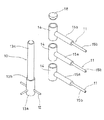
この目地用遮断柵1は、目地sを介して立設された一対の支持杆10,10と、該両支持杆10,10に、上下方向に所定間隔で横架された複数の伸縮杆11とからなり、各伸縮杆11の端部は、前記両支持杆10,10に対して連結手段を介して少なくとも水平方向に回動可能に連結されている。
【0015】
各支持杆10は、アンカー12が側方突成された円柱状の基部13aと、その上部に段部13bを介して若干小径に形成された円柱状の回動支持部13cとを備えてなり、基部13aを通路5の床に埋設して立設されている。また、回動支持部13cには、伸縮杆11の数に応じて上下方向に分割された円筒状の複数の回動管14が水平方向に回動可能に外嵌されている。ここで、最上部に位置する回動管14の上端に円形キャップ18を被着して、その上端開口部を遮蔽するようにしてもよい。
【0016】
一方、前記各伸縮杆11は、両側端部に配置された円筒状の基管15a,15aと、該基管15a,15aの対向する先端部から該基管15a,15a内に端部が夫々進退可能に嵌挿されて両基管15a,15aを繋ぐ連繋杆15bとからなり、該連繋杆15bの端部を基管15a,15a内で相対的に進退させることによって、その全体長を伸縮し得るようになっている。また、図3に示すように、基管15a,15a内に嵌挿された連繋杆15bの両側端には円形の鍔縁16,16が夫々固着されており、伸縮杆11の伸長時に、該鍔縁16,16を基管15a,15aの先端部に形成された抜け止め縁17,17に当接させて、その抜け止めを行うようにしている。
【0017】
前記各伸縮杆11は、その基管15a,15aの基部側の端部が、前記各支持杆10の回動支持部13cに外嵌された複数の回動管14の外周面に溶接等を介して夫々固定されている。そして、この伸縮杆11の端部を固定した回動管14によって、各伸縮杆11の端部を支持杆10に対して水平方向に回動可能に連結する連結手段が構成されている。尚、回動管14は上記のように複数に分割することなく、図5に示すように、単一の円筒管によって構成することも可能である。
【0018】
かかる構成からなる目地用遮断柵1にあって、地震時に、隣接する建物が離近方向(目地に直交する方向)に相対変位すると、両支持杆10,10間に横架された各伸縮杆11がその変位量に応じて伸縮して、前記離近方向の相対変位に追従する。また、隣接する建物が前後方向(目地に沿う方向)に相対変位すると、各伸縮杆11が伸縮するとともに、回動管14の回動作用を介して各伸縮杆11の端部が支持杆10,10に対して水平方向に回動して、その相対変位に追従する。これにより、目地用遮断柵1は、隣接する建物の離近方向及び前後方向の各相対変位に無理なく追従し、支持杆10,10間に横架された複数の伸縮杆11によって、通路5の側部の間隙部9を支障なく遮断することができる。
【0019】
図6は第2の実施例を示し、この実施例は、上記第1実施例における連結手段の構成を変更したものである。目地sを介して立設される一対の支持杆10,10は、図面に示すように、夫々アンカー12が側方突成された基部13aからその上端まで同一径の円柱状に形成されており、両支持杆10,10の対向する外周面に上下で一対の軸受片19,19が上下方向に所定間隔で複数対配設されている。各一対の軸受片19,19には、支軸20の上下両端が回動可能に枢結されており、該支軸20から側方に延成された取付け軸21に、伸縮杆11を構成する基管15aの基部側の端部が溶接,螺子止め等の固定手段を介して固定されている。
【0020】
そして、隣接する建物の前後方向の相対変位時に、支軸20の回動作用を介して、各伸縮杆11の端部が支持杆10,10に対して水平方向に回動し得るようになっている。これにより、各伸縮杆11の端部を支持杆10に対して水平方向に回動可能に連結する連結手段が構成されている。尚、支軸20から側方に延成された取付け軸21は必ずしも必要ではなく、基管15aの端部を直接支軸20に固定することも可能である。
【0021】
かかる構成からなる連結手段を備えた目地用遮断柵1にあっても、前記第1実施例のものと同様に、隣接する建物の離近方向及び前後方向の各相対変位に追従することができる。
【0022】
図7,図8は第3の実施例を示し、この実施例は、上記第1実施例における連結手段の構成を変更し、伸縮杆11の端部を支持杆10,10に対して水平方向及び上下方向に回動し得るようにしたものである。目地sを介して立設される一対の支持杆10,10は、図面に示すように、アンカー12が側方突成された円柱状の基部13aと、その上部に段部13bを介して若干小径に形成された円柱状の回動支持部13cとを備えてなり、該回動支持部13cには、伸縮杆11の数に応じて上下方向に分割された円筒状の複数の回動管14が水平方向に回動可能に外嵌される。ここで、最上部に位置する回動管14の上端に円形キャップ18を被着して、その上端開口部を遮蔽するようにしてもよい。
【0023】
また、各回動管14の外周面には、左右で一対の軸受片19’,19’が夫々配設されている。この各一対の軸受片19’,19’には、支軸20の左右両端が回動可能に枢結されており、該支軸20から側方に延成された取付け軸21に、伸縮杆11を構成する基管15aの基部側の端部が溶接,螺子止め等の固定手段を介して固定されている。
【0024】
そして、隣接する建物の前後方向の相対変位時に、回動管14の回動作用を介して、各伸縮杆11の端部が支持杆10,10に対して水平方向に回動するとともに、隣接する建物の上下方向の相対変位時に、支軸20の上下方向の回動作用を介して、各伸縮杆11の端部が支持杆10,10に対して上下方向に回動し得るようになっている。これにより、各伸縮杆11の端部を支持杆10に対して水平方向及び上下方向に回動可能に連結する連結手段が構成されている。尚、この実施例にあっても、支軸20から側方に延成された取付け軸21は必ずしも必要ではなく、基管15aの端部を直接支軸20に固定するようにしてもよい。また、回動管14は上記のように複数に分割することなく、単一の円筒管(図5参照)によって構成することも可能である。
【0025】
かかる構成からなる連結手段を備えた目地用遮断柵1にあっては、前記第1,第2実施例のものと同様に、隣接する建物の離近方向及び前後方向の各相対変位に追従することができるとともに、隣接する建物の上下方向の相対変位にも追従し得るものとなる。
【0026】
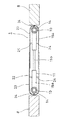
図9,図10は第4の実施例を示し、この実施例は、上記第1実施例の目地用遮断柵1をカバー体22によって被覆したものである。該カバー体22は、目地用遮断柵1の、少なくともその前後及び上面を覆い得る横断面略コ字形の左右のカバー23,23からなる。このカバー23,23は、先端側が対向状に延出され、その先端部分を摺動可能に重ね合わることにより、伸縮可能に設けられている。また、両カバー23,23の基部側は、図10に示すように、支持杆10,10に外嵌された回動管14,14と、各伸縮杆11の基管15a,15aとに複数の連結杆24,24を介して夫々支持されており、各伸縮杆11の水平方向の回動に対して、追従回動し得るようになっている。
【0027】
かかる構成にあって、地震時に、隣接する建物が離近方向(目地に直交する方向)に相対変位し、両支持杆10,10間に横架された各伸縮杆11がその変位量に応じて伸縮すると、カバー23,23も同様に伸縮して、その相対変位に追従する。また、隣接する建物が前後方向(目地に沿う方向)に相対変位し、各伸縮杆11の端部が支持杆10,10に対して水平方向に回動すると、カバー23,23も同様に回動して、その相対変位に追従する。これにより、カバー23,23は、目地用遮断柵1の追従機能を損なうことなく、通路5の側部の間隙部9を遮蔽することができる。また、目地用遮断柵1を覆い隠すことができ、その美観を向上させることができる。
【0028】
尚、前記カバー23,23は、第2実施例の目地用遮断柵1にも適用することが可能である。この場合には、両カバー23,23の基部側を、各伸縮杆11の基管15a,15aに支持させることにより、各伸縮杆11の水平回動に両カバー23,23を追従させることができる。
【0029】
また、本発明にかかる目地用遮断柵1は、免震装置によって下部が支持された免震構造の建物以外の一般的な建物にも適用することが可能である。
【0030】
【発明の効果】
本発明は上述のように、目地sを介して一対の支持杆10,10を立設し、該両支持杆10,10に前記目地sを横断する複数の伸縮杆11を上下方向に所定間隔で横架するとともに、各伸縮杆11の端部を、前記両支持杆10,10に対して連結手段を介して少なくとも水平方向に回動可能に連結し、その連結手段を、外周面に伸縮杆11の端部が固定され、前記各支持杆10に外嵌して水平方向に回動可能とした単一もしくは上下方向に分割された複数の回動管14によって構成したり、あるいは、両支持杆10,10の対向する外周面に上下方向に所定間隔で複数対配設された上下で一対の軸受片19,19と、伸縮杆11の端部が固定され、前記各一対の軸受片19,19に上下両端が回動可能に枢結された支軸20とにより構成するようにしたから、隣接する建物が離近方向及び前後方向に相対変位しても、その相対変位に目地用遮断柵1が追従し、支持杆10,10間に横架された複数の伸縮杆11によって、通路5の側部の間隙部9を支障なく遮断することができる。
【0031】
また、前記連結手段を、両支持杆10,10に外嵌して水平方向に回動可能とした単一もしくは上下方向に分割された複数の回動管14と、該回動管14の外周面に上下方向に所定間隔で複数対配設された左右で一対の軸受片19’,19’と、伸縮杆11の端部が固定され、前記各一対の軸受片19’,19’に左右両端が回動可能に枢結された支軸20とにより構成して、伸縮杆11の端部を水平方向及び上下方向に回動可能とすることにより、隣接する建物の離近方向及び前後方向の相対変位に加えて、上下方向の相対変位に対しても目地用遮断柵1を追従させることができる。
【0032】
さらに、先端側が対向状に延出され、その先端部分を摺動可能に重ね合わせることにより、伸縮可能に設けられた左右のカバー23,23を、前記両支持杆10,10及び各伸縮杆11に追従回動可能に被覆するようにしたから、隣接する建物の離近方向及び前後方向の相対変位に対する目地用遮断柵1の追従機能を損なうことなく、通路5の側部の間隙部9を遮蔽することができるとともに、目地用遮断柵1を覆い隠すことができ、美観を向上させ得る等の優れた効果がある。
【図面の簡単な説明】
【図1】本発明に係る目地用遮断柵の第1実施例の施工状態の縦断正面図である。
【図2】同上の施工状態の平面図である。
【図3】第1実施例の一部切欠正面図である。
【図4】同上の支持杆及び連結手段を示す分解斜視図である。
【図5】回動管の他の構成を示す分解斜視図である。
【図6】第2実施例の支持杆及び連結手段を示す斜視図である。
【図7】第3実施例の支持杆及び連結手段を示す斜視図である。
【図8】同上の平面図である。
【図9】第4実施例の施工状態の正面図である。
【図10】同上の横断平面図である。
【符号の説明】
s 目地
x 建物
1 目地用遮断柵
5 通路
9 間隙部
10 支持杆
11 伸縮杆
14 回動管
19 軸受片
19’軸受片
20 支軸
23 カバー[0001]
BACKGROUND OF THE INVENTION
The present invention relates to a joint barrier fence disposed at a joint position on a side portion of a passage connecting two buildings across a joint located between adjacent buildings.
[0002]
[Prior art]
In recent years, in order to keep damage caused by earthquakes to a minimum, some buildings have been constructed that support the lower part with a seismic isolation device having a buffer function.
[0003]
[Problems to be solved by the invention]
In such a base-isolated structure, when a joint cover device is arranged on the joint portion of a passage such as a passageway that connects the two buildings across the joint located between adjacent buildings, A known floor joint cover device can be applied, but there are few joint cover devices that can be applied to the gap portion on the side of the passage, and in particular, there is no barrier fence that can be used to block the gap portion. It is.
[0004]
The object of the present invention is to provide a joint fence for joints that can solve the conventional problems.
[0005]
[Means for Solving the Problems]
The present invention is arranged at a joint position on a side portion of a passage connecting two buildings across a joint located between adjacent buildings, and a pair of support rods are provided via the joint. A plurality of telescopic rods crossing the joints are horizontally mounted on the two support rods at predetermined intervals in the vertical direction, and the end portions of the respective telescopic rods are at least connected to the both support rods via a connecting means. It is the jointing fence for joints characterized by being connected so that rotation in a horizontal direction is possible.
[0006]
In such a configuration, the present invention divides the connecting means in a single or vertical direction in which an end of an expansion / contraction rod is fixed to the outer peripheral surface and is fitted on the support rod so as to be horizontally rotatable. Or a pair of upper and lower bearing pieces arranged at predetermined intervals in the vertical direction on the opposing outer peripheral surfaces of the two support rods, and ends of the expansion and contraction rods. The upper and lower ends are pivotally connected to the pair of bearing pieces so as to be pivotable .
[0007]
In such a configuration, when an adjacent building is relatively displaced in a close-up direction (a direction perpendicular to the joint) at the time of an earthquake, the expansion / contraction bar extends and follows the relative displacement. When the adjacent building is relatively displaced in the front-rear direction (in the direction along the joint), the telescopic heel expands and contracts, and the end of the telescopic heel rotates in the horizontal direction with respect to the support heel to follow the relative displacement. To do. Thereby, even if the adjacent building is relatively displaced in the direction of separation and front-rear direction, the gap portion on the side of the passage can be shut off without any trouble by the plurality of telescopic rods installed horizontally between the support rods.
[0008]
Further, in the above-described configuration, the connecting means is fitted with both support rods so as to be rotatable in the horizontal direction, and a plurality of rotating tubes divided in the vertical direction or the outer periphery of the rotating tubes A pair of left and right bearing pieces, which are arranged in pairs on the surface at predetermined intervals in the vertical direction, and the ends of the telescopic rods are fixed, and the left and right ends are pivotally connected to the pair of bearing pieces. It can also be constituted by a shaft. In this configuration, the end of each telescopic rod can be rotated in the horizontal direction and the vertical direction, and the telescopic rod can follow the relative displacement of the adjacent building in the direction of separation, front-back direction, and vertical direction. .
[0009]
Further, in the above-described configuration, the distal end side is extended in an opposing manner, and the distal end portions are slidably overlapped, so that the left and right covers provided in an extendable manner are attached to the both support rods and the respective extendable rods. You may make it coat | cover so that a follow-up rotation is possible. In this configuration, the gap portion on the side of the passage can be shielded without impairing the follow-up function of the blocking fence, and the aesthetic appearance can be improved by covering the blocking fence.
[0010]
DETAILED DESCRIPTION OF THE INVENTION
A first embodiment of the present invention will be described with reference to FIGS.
[0011]
In the drawings,
[0012]
As shown in FIG. 2, the building x is formed with a corridor 4 that is continuous with the passage corridor y. The corridor 4 and the passage corridor y allow the two buildings to cross the joint s located between adjacent buildings. A connecting
[0013]
[0014]
This
[0015]
Each
[0016]
On the other hand, each of the
[0017]
Each of the
[0018]
In the
[0019]
FIG. 6 shows a second embodiment, which is a modification of the configuration of the connecting means in the first embodiment. As shown in the drawing, the pair of
[0020]
Then, at the time of relative displacement in the front-rear direction of the adjacent building, the end portions of the
[0021]
Even in the
[0022]
7 and 8 show a third embodiment. In this embodiment, the configuration of the connecting means in the first embodiment is changed, and the end of the
[0023]
A pair of bearing
[0024]
And when the relative displacement of the adjacent building in the front-rear direction, the end of each
[0025]
In the
[0026]
9 and 10 show a fourth embodiment. In this embodiment, the
[0027]
In such a configuration, at the time of an earthquake, adjacent buildings are relatively displaced in the direction of separation (a direction perpendicular to the joint), and each
[0028]
In addition, the said covers 23 and 23 are applicable also to the interruption | blocking
[0029]
Further, the
[0030]
【The invention's effect】
In the present invention, as described above, a pair of
[0031]
Further, the connecting means is fitted around the
[0032]
Further, the left and right covers 23, 23 are provided so that they can extend and contract by extending the tip side so as to face each other and slidably superimposing the tip parts, so that the
[Brief description of the drawings]
FIG. 1 is a longitudinal front view of a construction state of a first embodiment of a joint barrier according to the present invention.
FIG. 2 is a plan view of the construction state of the above.
FIG. 3 is a partially cutaway front view of the first embodiment.
FIG. 4 is an exploded perspective view showing the support rod and connecting means.
FIG. 5 is an exploded perspective view showing another configuration of the rotating tube.
FIG. 6 is a perspective view showing a support rod and connecting means of a second embodiment.
FIG. 7 is a perspective view showing a support rod and connecting means of a third embodiment.
FIG. 8 is a plan view of the same.
FIG. 9 is a front view of a construction state of the fourth embodiment.
FIG. 10 is a transverse plan view of the above.
[Explanation of symbols]
s
Claims (4)
前記目地を介して一対の支持杆を立設し、該両支持杆に前記目地を横断する複数の伸縮杆を上下方向に所定間隔で横架するとともに、各伸縮杆の端部は、前記両支持杆に対して連結手段を介して少なくとも水平方向に回動可能に連結されてなり、
さらに前記連結手段を、外周面に伸縮杆の端部が固定され、前記支持杆に外嵌して水平方向に回動可能とした単一もしくは上下方向に分割された複数の回動管によって構成したものであることを特徴とする目地用遮断柵。It is arranged at the joint position on the side of the passage connecting the two buildings across the joint located between adjacent buildings,
A pair of support rods are erected through the joints, and a plurality of telescopic rods crossing the joints are horizontally mounted on the two support rods at predetermined intervals in the vertical direction. It is connected to the support rod via a connecting means so as to be rotatable at least in the horizontal direction ,
Further, the connecting means is constituted by a single or a plurality of vertically divided rotating pipes which are fixed to the outer peripheral surface with end portions of the expansion and contracting rods and are fitted on the supporting rods so as to be horizontally rotatable. joint for blocking fence, characterized in that to those were.
Priority Applications (1)
| Application Number | Priority Date | Filing Date | Title |
|---|---|---|---|
| JP20962897A JP3929558B2 (en) | 1997-07-17 | 1997-07-17 | Intersection fence |
Applications Claiming Priority (1)
| Application Number | Priority Date | Filing Date | Title |
|---|---|---|---|
| JP20962897A JP3929558B2 (en) | 1997-07-17 | 1997-07-17 | Intersection fence |
Publications (2)
| Publication Number | Publication Date |
|---|---|
| JPH1136545A JPH1136545A (en) | 1999-02-09 |
| JP3929558B2 true JP3929558B2 (en) | 2007-06-13 |
Family
ID=16575954
Family Applications (1)
| Application Number | Title | Priority Date | Filing Date |
|---|---|---|---|
| JP20962897A Expired - Fee Related JP3929558B2 (en) | 1997-07-17 | 1997-07-17 | Intersection fence |
Country Status (1)
| Country | Link |
|---|---|
| JP (1) | JP3929558B2 (en) |
Families Citing this family (2)
| Publication number | Priority date | Publication date | Assignee | Title |
|---|---|---|---|---|
| JP4398715B2 (en) * | 2003-12-24 | 2010-01-13 | 株式会社日立製作所 | Passenger conveyor |
| GB2416369B (en) * | 2004-07-16 | 2009-03-04 | Antwise Ltd | Modular expandable plastic safety enclosure for the construction industry |
-
1997
- 1997-07-17 JP JP20962897A patent/JP3929558B2/en not_active Expired - Fee Related
Also Published As
| Publication number | Publication date |
|---|---|
| JPH1136545A (en) | 1999-02-09 |
Similar Documents
| Publication | Publication Date | Title |
|---|---|---|
| CN207998949U (en) | A kind of construction of fire-proof and thermal-insulation wallboard | |
| JP3929558B2 (en) | Intersection fence | |
| JPH03166452A (en) | Expansion and contraction structure for roof connection | |
| JP3806519B2 (en) | Protective fence mounting structure | |
| JP2000110414A (en) | Shutoff fence | |
| KR101310006B1 (en) | Bracket for fence and fence having the same | |
| JP4216955B2 (en) | Seismic isolation piping system and bellows type expansion joint with legs | |
| JPH1150629A (en) | Handrail mechanism of passage between adjacent ridge | |
| JP3276066B2 (en) | Floor joint equipment | |
| JP7365867B2 (en) | frame | |
| JP2020079607A (en) | Universal joint for long body covers | |
| JP7024993B2 (en) | Joint cover device for walls | |
| KR102512568B1 (en) | Soundproof tunnel with seismic structure | |
| KR102272051B1 (en) | a Shutter Consisting of Two Different Types of Slats | |
| JP4976981B2 (en) | Ceiling joint cover device | |
| JP3079365B2 (en) | Seismic isolation structure | |
| JP3630530B2 (en) | Building with telescopic passage | |
| JPH0528299Y2 (en) | ||
| JP2829710B2 (en) | Protective fence | |
| JP2020079644A (en) | Universal joint for long body covers | |
| JPH1181499A (en) | Cutoff screen device | |
| KR20170087757A (en) | Assembly type soundproof unit and soundproof barrier | |
| JP4890156B2 (en) | Access blocking device and installation structure thereof | |
| KR102651890B1 (en) | Anti-seismic cable tray | |
| JPH0755179A (en) | Drain piping structure for air conditioner in preassembled type building and method for piping |
Legal Events
| Date | Code | Title | Description |
|---|---|---|---|
| A621 | Written request for application examination |
Free format text: JAPANESE INTERMEDIATE CODE: A621 Effective date: 20040715 |
|
| A977 | Report on retrieval |
Free format text: JAPANESE INTERMEDIATE CODE: A971007 Effective date: 20060209 |
|
| A131 | Notification of reasons for refusal |
Free format text: JAPANESE INTERMEDIATE CODE: A131 Effective date: 20060929 |
|
| A521 | Written amendment |
Free format text: JAPANESE INTERMEDIATE CODE: A523 Effective date: 20061101 |
|
| TRDD | Decision of grant or rejection written | ||
| A01 | Written decision to grant a patent or to grant a registration (utility model) |
Free format text: JAPANESE INTERMEDIATE CODE: A01 Effective date: 20070205 |
|
| A61 | First payment of annual fees (during grant procedure) |
Free format text: JAPANESE INTERMEDIATE CODE: A61 Effective date: 20070307 |
|
| R150 | Certificate of patent or registration of utility model |
Free format text: JAPANESE INTERMEDIATE CODE: R150 |
|
| FPAY | Renewal fee payment (event date is renewal date of database) |
Free format text: PAYMENT UNTIL: 20130316 Year of fee payment: 6 |
|
| FPAY | Renewal fee payment (event date is renewal date of database) |
Free format text: PAYMENT UNTIL: 20130316 Year of fee payment: 6 |
|
| FPAY | Renewal fee payment (event date is renewal date of database) |
Free format text: PAYMENT UNTIL: 20160316 Year of fee payment: 9 |
|
| R250 | Receipt of annual fees |
Free format text: JAPANESE INTERMEDIATE CODE: R250 |
|
| LAPS | Cancellation because of no payment of annual fees |