JP3920742B2 - Abnormal sound source search method and sound source search apparatus - Google Patents
Abnormal sound source search method and sound source search apparatus Download PDFInfo
- Publication number
- JP3920742B2 JP3920742B2 JP2002249004A JP2002249004A JP3920742B2 JP 3920742 B2 JP3920742 B2 JP 3920742B2 JP 2002249004 A JP2002249004 A JP 2002249004A JP 2002249004 A JP2002249004 A JP 2002249004A JP 3920742 B2 JP3920742 B2 JP 3920742B2
- Authority
- JP
- Japan
- Prior art keywords
- sound source
- sound
- abnormal
- waveform
- microphone
- Prior art date
- Legal status (The legal status is an assumption and is not a legal conclusion. Google has not performed a legal analysis and makes no representation as to the accuracy of the status listed.)
- Expired - Fee Related
Links
Images


Description
【0001】
【発明の属する技術分野】
本発明は、異常音の音源探査方法及び音源探査装置、特に、所定の音源探査領域内で発生している異常音の音源特定を高精度に行うことのできる異常音の音源探査方法及び音源探査装置の改良に関する。
【0002】
【従来の技術】
工場等における設備や装置等を含む機器の稼働状態の異常は迅速に発見する必要がある。通常、機器の異常は、設備や装置が個別に有している自己診断機能によって、動作異常を検出し、警報出力処理や動作停止処理等を行っている。また、機械的な駆動部を含む機器においては、現実の動作不良に至る前の段階で、駆動部を構成するモータ部分やベアリング部分等で摩耗や形状変形、潤滑剤の欠乏等により摩擦が増加し、正常動作時には発生しない異常音を発生することがある。このような異常音は、初期の段階では機器の正常動作に影響しないが、徐々に影響が拡大し、突然の警報出力や動作停止を招く。
【0003】
このような異常音の検出は、現場管理者等が自らの聴覚によって異常音の認識を行い、さらに、異常音発生位置の探査を行うことで対応する場合が多い。また、この異常音検出を検出器によって行う場合もある。この検出器を用いた方法は、例えば複数のマイクロフォンにより機器の設置された施設内で現在発せられている現在音波形を収集し、この収集した現在音波形と予め収集しておいた異常音を含まない基準音波形との比較を行うことにより、異常音の発生の検出を行うと共に、異常音源から異常音が各マイクロフォンに到達するまでの時間差を求め、この時間差に基づいて、異常音発生位置を逆算し特定している。このような異常音検出システムは、例えば特開2000−214052号公報に開示されている。このシステムによれば、周囲音に影響されることのない異常音源探査を行うことができる。
【0004】
【発明が解決しようとする課題】
しかし、各マイクロフォンから異常音源までの距離が個々に異なるため、各マイクロフォンに到達する波形が減衰してしまい、同一の音源から発せられた波形であるにも関わらず、異なる波形(異なる音)であると誤認識してしまう場合がある。つまり、複数の異常音波形の比較をそのまま行おうとすると、音の伝搬時に発生した減衰がノイズ成分となり、同じ音源から発せられた音の波形であるにも関わらず、比較する両者の波形の相関性が低下するためである。さらに、同一の音源探査領域内に複数の異常音発生源が存在する場合、異常音と認識される波形が複数存在し、各波形に対する相関精度の信頼性がさらに低下してしまう。異常音を発生している音源が1つの場合、相関性が低い場合でも同一音源からの異常音であると見なし時間差を算出することもできるが、この処理により、時間差の新たな誤差要因となる。また、異常音を発している音源が多数存在する場合、相関の信頼性がさらに低下し、正確な時間差は算出することができないという問題がある。
【0005】
その結果、音源から異常音が各マイクロフォンに到達するまでの時間差を正確に算出することができず、結果的に異常音源の特定精度の信頼性が低下してしまうという問題がある。
【0006】
本発明は、上記課題に鑑みなされたものであり、異常音の音源特定を容易かつ高精度に行うことのできる異常音の音源探査方法及び音源探査装置を提供することを目的とする。
【0007】
【課題を解決するための手段】
上記のような目的を達成するために、本発明は、音源探査領域内の異なる位置に配置された3本以上のマイクロフォンを用いて音源探査領域内で機器が稼働している時に発生している現在音波形を収集するステップと、前記音源探査領域内で機器が正常稼働している時に各マイクロフォンで収集した基準音波形と前記現在音波形との差分を求め異常音波形を抽出するステップと、抽出した異常音波形の位相情報を求めるステップと、任意の2本のマイクロフォンで収集した現在音波形から抽出された異常音波形の位相情報の相互相関をとり同一音源からの異常音が各マイクロフォンに到達するまでの時間差を求めるステップと、各マイクロフォンの組み合わせで求めた時間差に基づいて、異常音の音源位置を特定するステップと、を含むことを特徴とする。
【0008】
また、上記のような目的を達成するために、本発明は、音源探査領域内の異なる位置に配置され、音源探査領域内で機器が稼働している時に発生している現在音波形を収集する少なくとも3本のマイクロフォンと、前記音源探査領域内で機器が正常稼働している時に発生している基準音波形を記憶する基準音記憶部と、各マイクロフォンに関し、同一位置で収集した現在音波形と基準音波形とを比較し異常音波形を抽出する比較部と、抽出した各異常音波形から位相情報を求める波形処理部と、任意の2本のマイクロフォンで収集し現在音波形から抽出された異常音波形の位相情報の相互相関をとり同一音源からの異常音が各マイクロフォンに到達する時間差を求める時間差算出部と、各マイクロフォンの組み合わせで求めた時間差に基づいて、異常音の音源位置を特定する音源特定部と、を含むことを特徴とする。
【0009】
ここで、現在音波形とは、音源探査領域内に存在する全ての音で構成される波形であり、機器が正常稼働時に発している正常音及び異常稼働時に発せられる異常音(異常稼働に至る前の予兆段階の音も含む)、音源探査領域内に存在するバックグラウンドの音も含むものとする。一方、基準音波形とは、同様に音源探査領域内に存在する全ての音で構成される波形であり、音源探査領域内に存在するバックグラウンドの音や正常音を含むが、異常音は含まないものである。この基準音は、例えば、機器が正常稼働することが確認されている時、例えば、機器全ての一斉メンテナンスが終了した後等に得ることが好ましい。また、音源探査領域内に存在する機器とは、領域内に存在する音を発生する全ての設備や装置を含むものとする。
【0010】
上記構成によれば、ノイズの原因となる振幅情報を排除した残余情報を用いて相互相関をとるので、相互の情報相関性の認識精度が向上し、同一音源からの異常音が各マイクロフォンに到達する時間差を高精度に求めることができる。その結果、異常音の音源位置の特定を正確に行うことができる。この場合、異常音の音源が1つである場合はもとより複数存在する場合も、個々の異常音の相関性を正確に把握することができるので、正確な音源探査を行うことができる。
【0011】
また、上記のような目的を達成するために、本発明は、上記構成において、特定した音源位置に基づいて、音源探査領域内に存在する機器の対応位置を特定するステップと、特定した対応位置の機器に関する情報を記憶部から読み出し提示するステップと、を含むことを特徴とする。
【0012】
また、上記のような目的を達成するために、本発明は、上記構成において、特定した音源位置に対応する音源探査領域内の機器の対応位置に関する情報を検索する検索部と、検索した情報を提示する提示部と、を含むことを特徴とする。
【0013】
ここで、機器の対応位置に関する情報とは、例えば、機器そのものの情報や機器構成部品の詳細(部品の型式、図面、スペック等)やその構成部品の前回交換時期等の履歴、寿命情報等や次回交換予定時期等を含んでいる。
【0014】
この構成によれば、異常音の音源を明確に管理者に提示することが可能であり、迅速なメンテナンスを行うことができる。
【0015】
また、上記のような目的を達成するために、本発明は、上記構成において、特定した音源位置に基づき、音源探査領域内の音源の対応位置の画像を取得する撮像手段を制御するステップと、取得した画像を提示するステップと、を含むことを特徴とする。
【0016】
また、上記のような目的を達成するために、本発明は、上記構成において、特定した音源位置に基づき、音源探査領域内の音源対応位置の画像を取得する撮像部と、撮像した画像を提示する提示部と、を含むことを特徴とする。
【0017】
この構成によれば、異常音の音源をさらに明確に管理者に提示することが可能であり、効率的なメンテナンスを行うことができる。
【0018】
【発明の実施の形態】
以下、本発明の好適な実施の形態(以下、実施形態という)を図面に基づき説明する。
【0019】
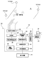
図1は、本実施形態の異常音の音源探査方法を実現する音源探査装置10の構成概念を説明する構成ブロック図である。音源探査装置10は、音源探査領域Aの任意の位置で当該音源探査領域A内に存在する音を収集する少なくとも3本のマイクロフォン12(図1では一例として3本のマイクロフォン12a,12b,12cを図示する)と、収集した現在音波形に基づき、音源探査領域Aに存在する装置や設備等の機器が発している異常音の音源を特定する処理部14と、特定した異常音の音源の提示やその音源に関する情報を提示する提示部としての表示装置16で構成されている。なお、音源探査領域Aは、例えば、工場内で複数の工作機械や組立ロボット等の駆動型設備や装置等が配置された工程や機械室等の特定範囲を意味し、マイクロフォン12は、設備等が稼働している時の音源探査領域Aの音(現在音波形)を収集する。ここで、現在音波形とは、音源探査領域A内に存在する全ての音で構成される波形であり、設備等が正常稼働時に発している正常音及び異常稼働時に発せられる異常音(異常稼働に至る前の予兆段階の音も含む)、音源探査領域A内に存在するバックグラウンドの音も含むものとする。
【0020】
また、本実施形態の音源探査装置10は異常音の音源となっている位置の画像情報、例えば、音源となっている設備の映像や、さらに詳細に音源となっているベアリング等の部品が使用されている位置の映像を提示するために撮像装置としてCCDカメラ18等が接続されている。また、実際に特定した異常音の音源位置に基づいて、CCDカメラ18を音源位置に向けたり、その位置をズームするためのカメラ駆動部20が接続されている。
【0021】
なお、本実施形態の音源探査装置10に用いるマイクロフォン12は無指向性マイクロフォンであり、音源探査領域A内に任意の間隔、望ましくは等間隔で複数本配置されている。また、CCDカメラ18も音源探査領域A内で監視対象となっている設備や装置等機器の全てを撮影できるように各所に複数個配置されていることが望ましい。
【0022】
音源探査装置10の処理部14には、各マイクロフォン12を用いて音源探査領域A内の音波形(音源探査中に収集する現在音波形及び、前準備として異常音が発生していないことが明らかな時に収集する基準音波形)を収集する音波形収集部22と、各マイクロフォン12により、音源探査領域A内の機器が異常音を発すること無く正常稼働している時の音(基準音波形)を予め取得しておき記憶しておく基準音波形記憶部24と、各マイクロフォン12毎に収集した現在音波形と予め記憶しておいた、対応するマイクロフォンにおける基準音波形との比較を行い、その差分を求めて異常音波形のみを抽出する比較部26を含んでいる。
【0023】
また、抽出した異常音波形から振幅情報のみを排除して残余情報を抽出する残余情報抽出部(波形処理部)28と、任意の2本のマイクロフォンで収集した現在音波形に基づく残余情報の相互相関をとり、同一音源からの異常音が各マイクロフォンに到達するまでの時間差を任意の2本のマイクロフォン12の組み合わせ毎に算出する時間差算出部30と、各マイクロフォン12の組み合わせにより算出した時間差に基づいて、異常音の音源位置を特定する音源特定部32を含んでいる。特定した音源位置に関する情報を表示装置16に表示するための表示制御部34には、音源位置に関する情報を記憶した情報記憶部36が接続され、異常音の発生位置の特定だけでなく、異常音を発している部品の具体的な関連情報や、異常音を解消するための処置、例えば、部品の交換や調整等のメンテナンス作業を迅速かつ正確に行うための情報を提供できるようになっている。この情報は、具体的には、機器構成部品の詳細である部品の型式、図面、スペック等やその構成部品の前回交換時期等の履歴情報、寿命情報、また、次回交換予定時期等を含むことが好適である。
【0024】
さらに、音源特定部32には、カメラ制御部38が接続され、カメラ駆動部20を動作させ、特定した異常音の音源の方向にCCDカメラ18を迅速に向けるようになっている。CCDカメラ18により現実に異常音を発生している部分が表示されることにより、管理者に対する視覚的情報を増加することが可能であると共に、部品の交換や調整等のメンテナンス作業をさらに迅速に行うことが可能になる。また、前述したように、情報記憶部36に対象部品の交換方法等のメンテナンス手順を記憶させておき、CCDカメラ18により取得された映像と共に、表示装置16にメンテナンス手順等を表示するようにすれば、不慣れな設備から異常音が発生していたとしても迅速にメンテナンス作業を行うことが可能となる。
【0025】
このように構成される音源探査装置10による異常音の音源探査手順を以下に説明する。
【0026】
まず、異常音の音源探査の前準備として、音波形収集部22は各マイクロフォン12を用いて、音源探査領域A内の機器が正常に稼働している時の音、すなわち、異常音を全く含まない状態の音源探査領域A内の音を基準音波形として、各マイクロフォン12毎に基準音波形記憶部24に記憶する。この基準音波形の収集は、例えば、音源探査領域A内の機器の総点検を行った後に最初に全機器を稼働させた時等に行うことが好ましい。
【0027】
音源探査装置10が実際に異常音の音源探査を行う場合、各マイクロフォン12に、音源探査領域A内の現在音波形の収集を常時行わせる。音波形収集部22は所定のサンプリング周波数で現在音波形を保持し、所定のタイミングで比較部26に、各マイクロフォン12毎のデータとして転送する。この時、比較部26に転送される現在音波形は、常時、音源探査領域A内で正常に稼働している機器から発せられる正常音と、部品の摩耗等が発生している機器から発せられる異常音とが混合されたものである。図2(a)は、正常音と異常音が混合されている現在音波形を模式的に示したもである。
【0028】
一方、比較部26は、マイクロフォン12aで収集された現在音波形が転送されると、基準音波形記憶部24に記憶されているマイクロフォン12aで収集した基準音波形を読み出し、両者の比較を行いその差分を算出する。図2(b)には、基準音波形記憶部24に記憶された基準音波形を模式的に示したものが示され、図2(c)には、現在音波形と基準音波形の差分をとった結果、得られる異常音のみの波形が模式的に示されている。つまり、比較部26は、マイクロフォン12aで収集した音のなかから異常音のみを抽出する処理を行っている。一般的な異常音の抽出は、バンドフィルタ等を用いて行うため所定周波数帯のみのS/N比が向上するが、上述のように、基準波形との比較を行うことにより全周波数帯のS/N比を向上させることが可能となり、後段の波形処理の精度を向上することができる。
【0029】
また、比較部26は、音波形収集部22からマイクロフォン12bで収集した現在音波形に関してもマイクロフォン12bで収集した基準音波形との比較を行いマイクロフォン12bで収集した異常音の抽出を行う。同様に、マイクロフォン12cで収集した現在音波形に関しても同様な処理を行い異常音を抽出する。
【0030】
なお、本実施形態において、異常音とは、機器を構成する部品、特に駆動部を構成するモータ部分やベアリング部分等で摩耗や形状変形、潤滑剤の欠乏等により摩擦が増加し、正常動作時には発生しない音を主として意味するが、その他、機器の不具合により発生する様々な音を含むものとする。
【0031】
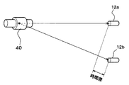
ところで、図3に示すように、ある機器(例えばベアリング40)で異常音が発生する場合、任意の位置に存在する例えばマイクロフォン12aまでの距離と、マイクロフォン12bまでの距離は異なる。つまり、異常音がマイクロフォン12に到達する時間に差が生じる。逆に、この時間差を正確に把握することができれば、異常音の音源位置を数学的手法により算出することができる。この時間差を算出する場合、一般には、波形の相互相関をとることにより、マイクロフォン12aで収集した波形とマイクロフォン12bで収集した波形の時間差を算出するが、音は伝搬中に減衰してしまうので、音源から異なる距離に存在するマイクロフォン12aとマイクロフォン12bでは、全く異なる波形が収集され、同一音源から発せられた波形であるにも関わらず、相互相関を良好にとることができない、言い換えれば信頼性の高い時間差を算出することができないことになる。これは、波形の振幅の減衰がノイズ情報として波形に載ってしまうためである。
【0032】
そこで、本実施形態においては、残余情報抽出部28が、異常音波形から振幅情報を排除する処理を行い、ノイズ成分が無い状態のデータから時間差を算出することにより精度及び信頼性の向上を図っている。具体的には、図4に示すように、マイクロフォン12aで収集した異常音波形a1をフーリエ変換し、少なくとも振幅情報b1と位相情報c1とに分離する。同様に、マイクロフォン12bで収集した異常音波形a2にフーリエ変換を施し、振幅情報b2と位相情報c2とに分離する。前述したように、マイクロフォン12aで収集した異常音波形a1とマイクロフォン12bで収集した異常音波形a2とは、同一の音源から発せられた異常音であるが、到達距離が異なるため、振幅と到達時間が異なる波形として認識されている。
【0033】
さらに、残余情報抽出部28は分離した位相情報c1と位相情報c2のみを合成し、合成波形dを作成し、時間差算出部30に提供する。時間差算出部30では、取得した合成波形dに対し逆フーリエ変換を施し、相関波形eを作成する。ここで作成される相関波形eでは、図5(a)に示すように、同じ音源から発せられた波形を2本のマイクロフォン12a,12bで収集した場合の時間差t1に相当するところに度数のピークが表れる。つまり、2本のマイクロフォン12aとマイクロフォン12bとでは、異常音の到達時間に例えばt1=10msの時間差があるということが検出される。
【0034】
前述したように、異常音波形が有する位相情報のみを利用し、音源とマイクロフォン12との距離の違いによる減衰の影響を排除することにより、マイクロフォン12a,12bで収集した異常音の相互相関を良好にとることが可能になり、時間差を明確に算出すること可能となる。
【0035】
同様に、残余情報抽出部28及び時間差算出部30では、マイクロフォン12bとマイクロフォン12cで取得した異常音波形に対して処理を行い時間差t2(図5(b)参照)及び、マイクロフォン12cとマイクロフォン12aで取得した異常音波形に対して処理を行い時間差t3(図5(c)参照)を算出し、算出した時間差t1,t2,t3を音源特定部32に供給する。
【0036】
音源特定部32では、時間差t1を取得すると、図6に示すように、マイクロフォン12aと架空の音源42との間の音の到達時間mとマイクロフォン12bと音源42との間の音の到達時間nとの時間差がt1になるような候補点p1,p2,p3・・・を結ぶ回転双曲線面S1を作成する。すなわち、マイクロフォン12a,12bに対して、時間差t1を形成し得る音源42は、回転送曲線面S1のいずれかに位置することになる。
【0037】
音源特定部32では、同様に、マイクロフォン12b,12cに関する時間差t2による回転双曲線面S2及びマイクロフォン12c,12aに関する時間差t3による回転双曲線面S3を作成する。もちろん、音源42は、この回転双曲線面S2,S3上のいずれかに位置することになる。従って、音源特定部32は、図7に示すように、作成した回転双曲線面S1,S2,S3の交わる位置を検索することにより、現実の異常音を発している音源44の位置を確定することができる。
【0038】
音源特定部32は現実の異常音を発している音源44の位置をXYZ座標軸上で確定すると、表示制御部34に対して、確定した異常音を発している音源44の座標を転送する。音源特定部32は音源44の座標に基づき、情報記憶部36を検索し、対応する座標に存在する機器の情報、さらに、その機器で音源44の座標と一致する部品に関する情報を呼び出す。例えば、図8に示すように、「設備Aの主軸ベアリングB:型式=○○○」等を表示装置16に表示させる。また、この時、検索した異常音の音源を構成する部品のCAD図面を情報記憶部36または他のデータベースから呼び出し表示したり、その部品のスペックや、寿命曲線、交換履歴、次回交換予定時期等を併せて表示してもよい。さらには、異常音の音源を構成する部品の交換手順等を示してもよい。
【0039】
また、本実施形態において、音源特定部32で異常音の音源44の座標を特定できたら、その座標をカメラ制御部38に供給している。カメラ制御部38では、取得した異常音の音源44の座標に基づいて、該当座標の近傍にあるCCDカメラ18のカメラ駆動部20を駆動して、CCDカメラ18を該当座標、つまり、異常音を発している機器に向けて、その映像を表示装置16に表示する。なお、表示する画像は、実際に異常音を発している部品のみでもよいし、対象となる機器全体や、機器の特定部分、さらには、各画像の並列表示等を行ってもよい。また、この時、図8に示すように、前述した各種情報と共に表示するようにしてもよい。
【0040】
このように、異常音の音源位置に関する各種情報を表示することにより、異常音の音源を明確に管理者に提示することが可能になると共に、異常音の原因を認識した後のメンテナンス作業を効率的に行うことができる。また、部品のCAD図面、交換方法、現実の部品の映像等を相互に参照することにより、さらにスムーズなメンテナンス作業を行うことができる。もちろん、図8に示す表示内容は一例であり、異常音の音源44の座標に基づいて検索できる情報の種類を適宜増減表示することが望ましい。
【0041】
ところで、音源探査領域Aでは、通常複数の機器が同時に稼働しているので、同じ時期に複数の機器から異常音が発せられる場合がある。つまり、異常音の音源が複数同時に存在する場合がある。この場合も基本的には、上述した異常音が1つの場合と同様な処理を行うことにより個々の異常音の音源位置を特定するとができる。
【0042】
例えば、異常音の音源が3個存在した場合、マイクロフォン12aで収集される現在音波形は、正常音の中に3個の異常音P,Q,Rを含む波形となる。同様に、マイクロフォン12b,12cにおいて収集される波形も正常音の中に3個の異常音P,Q,Rが含む波形となる。
【0043】
その結果、比較部26における比較処理により算出される波形も3個の異常音波形を含むこととなる。ただし、この時、3つの異常音P,Q,Rの出現する順番は各マイクロフォン12までの距離に応じて異なる。
【0044】
残余情報抽出部28では、複数の異常音P,Q,Rを含む波形をフーリエ変換することにより、異常音P,Q,Rに応じた複数の位相情報を取得する。そして、マイクロフォン12a,12bで取得した位相情報に基づき合成波形を作成し、時間差算出部30において、逆フーリエ変換を行うことにより、図9(a)に示すような異なる音源から発せられた波形を2本のマイクロフォン12a,12bで収集した場合に、同一音源の時間差に相当するところに度数のピークが表れる。この場合、3つの位置にピーク値が表れる。同様に、図9(b)、図9(c)に示すように、マイクロフォン12b,12c及びマイクロフォン12c,12aで収集した場合の時間差に相当するところに度数のピークが表れる。なお、音源からマイクロフォン12までの距離は個々に異なるので、各異常音P,Q,Rが各マイクロフォン12に到達する時間も異なる。その結果、図9(a)〜図9(c)に示すように、異常音Pに関するピーク値p、異常音Qに関するピーク値q、異常音Rに関するピーク値rの出現の順番や度数は個々に異なる。ただし、各異常音P,Q,Rの位相情報を参照することにより、図9(a)〜図9(c)で出現したどのピーク値p,q,rがどの異常音P,Q,Rに対応するものかは認識することができる。
【0045】
音源特定部32は、各マイクロフォン12の組み合わせで取得した時間差の中から同一音源の異常音、例えば異常音Pに関するピーク値pに基づく時間差を抽出し、図6、図7で説明したものと同様に、異常音Pに関する回転双曲線面S1,S2,S3を作成し、異常音Pの音源位置の特定を行う。同様に、異常音Qに関するピーク値に基づく時間差を抽出し、回転双曲線面S1,S2,S3を作成し、異常音Qの音源位置の特定を行う。異常音Rに関しても同様である。
【0046】
このように、本実施形態においては、音源探査領域Aの中に異常音を発生している音源が複数存在する場合でも、高精度にその音源位置の特定を行うことができる。
【0047】
この場合も、異常音の音源が特定できた後、その音源に関連する情報を図8に示すように、個々に表示することにより、複数の音源がある場合でも管理担当者を混乱させることなく適切な対処を迅速に行わせることができる。
【0048】
なお、図1に示す構成は一例であり、同様な処理を行う機能を有していれば、各構成は任意であり、本実施形態と同様な効果を得ることが可能である。例えば、パーソナルコンピュータの処理機能を用いて実現したり、既存の波形分析装置に改良を加えて実現してもよい。
【0049】
【発明の効果】
本発明によれば、ノイズの原因となる振幅情報を排除した残余情報を用いて相互相関をとるので、相互の情報相関性の認識精度が向上し、同一音源からの異常音が各マイクロフォンに到達するまでの時間差を高精度に求めることができる。その結果、異常音の音源位置の特定を正確に行うことができる。この場合、異常音の音源が1つである場合はもとより複数存在する場合も、個々の異常音の相関性を正確に把握することができるので、正確な音源探査を行うことができる。
【図面の簡単な説明】
【図1】 本発明の実施形態に係る異常音の音源探査方法を実現する音源探査装置の構成概念を説明する構成ブロック図である。
【図2】 本発明の実施形態に係る異常音の音源探査方法において、収集した現在音波形から異常音波形を抽出することを説明する説明図である。
【図3】 本発明の実施形態に係る異常音の音源探査方法において、任意の2本のマイクロフォンに到達する音に時間差が生じることを説明する説明図である。
【図4】 本発明の実施形態に係る異常音の音源探査方法において、任意の2本のマイクロフォンに到達する音の時間差を算出する手順を説明する説明図である。
【図5】 本発明の実施形態に係る異常音の音源探査方法において、任意の2本のマイクロフォンの組み合わせによって得られる時間差を説明する説明図である。
【図6】 本発明の実施形態に係る異常音の音源探査方法において、任意の2本のマイクロフォンに到達する音の時間差に基づいて音源が存在する可能性のある回転双曲線面を求める手順を説明する説明図ある。
【図7】 本発明の実施形態に係る異常音の音源探査方法において、任意の2本のマイクロフォンの組み合わせによって求めた3個の回転双曲線面によって音源を特定することを説明する説明図である。
【図8】 本発明の実施形態に係る異常音の音源探査方法により特定した音源に関する情報の表示例を説明する説明図である。
【図9】 本発明の実施形態に係る異常音の音源探査方法のおいて、異常音の音源が複数(例えば3個)存在する場合に、任意の2本のマイクロフォンの組み合わせによって得られる時間差を説明する説明図である。
【符号の説明】
10 音源探査装置、12,12a,12b,12c マイクロフォン、14処理部、16 表示装置、18 CCDカメラ、20 カメラ駆動部、22 音波形収集部、24 基準音波形記憶部、26 比較部、28 残余情報抽出部、30 時間差算出部、32 音源特定部、34 表示制御部、36 情報記憶部、38 カメラ制御部。[0001]
BACKGROUND OF THE INVENTION
The present invention relates to an abnormal sound source search method and a sound source search device, and more particularly to an abnormal sound source search method and a sound source search capable of accurately identifying a sound source of an abnormal sound occurring in a predetermined sound source search region. It relates to the improvement of the device.
[0002]
[Prior art]
It is necessary to quickly detect abnormalities in the operating state of equipment including equipment and devices in factories. Normally, an abnormality in equipment is detected by a self-diagnostic function that each facility or apparatus has individually, and an alarm output process or an operation stop process is performed. In addition, in devices that include mechanical drive units, friction increases due to wear, shape deformation, lack of lubricant, etc. at the motor and bearing parts that make up the drive unit before the actual malfunction occurs. In addition, abnormal sounds that do not occur during normal operation may be generated. Such an abnormal sound does not affect the normal operation of the device in the initial stage, but the influence gradually increases, causing a sudden alarm output or an operation stop.
[0003]
In many cases, the detection of such an abnormal sound is dealt with by a site manager or the like recognizing the abnormal sound by his / her own hearing and further exploring the position where the abnormal sound occurs. Moreover, this abnormal sound detection may be performed by a detector. The method using this detector, for example, collects the current sound waveform currently emitted in the facility where the equipment is installed by using a plurality of microphones, and collects the collected current sound waveform and the abnormal sound collected in advance. Abnormal sound generation is detected by comparing with a reference sound waveform not included, and the time difference from the abnormal sound source until the abnormal sound reaches each microphone is obtained. The back is calculated and specified. Such an abnormal sound detection system is disclosed in, for example, Japanese Patent Application Laid-Open No. 2000-214052. According to this system, it is possible to search for an abnormal sound source that is not affected by ambient sounds.
[0004]
[Problems to be solved by the invention]
However, because the distance from each microphone to the abnormal sound source is different, the waveform that reaches each microphone is attenuated, and the waveform is from the same sound source, but it is a different waveform (different sound). It may be misrecognized as being. In other words, if you try to compare multiple abnormal sound waveforms as they are, the attenuation that occurred during the propagation of the sound becomes a noise component, which is the waveform of the sound emitted from the same sound source. This is because the property decreases. Furthermore, when a plurality of abnormal sound sources are present in the same sound source search area, there are a plurality of waveforms recognized as abnormal sounds, and the reliability of correlation accuracy for each waveform is further reduced. If there is one abnormal sound source, even if the correlation is low, the time difference can be calculated by considering it as an abnormal sound from the same sound source, but this process causes a new error factor for the time difference. . In addition, when there are a large number of sound sources emitting abnormal sounds, there is a problem that the reliability of the correlation is further lowered and an accurate time difference cannot be calculated.
[0005]
As a result, there is a problem in that the time difference until the abnormal sound reaches each microphone from the sound source cannot be accurately calculated, and as a result, the reliability of the specific accuracy of the abnormal sound source is lowered.
[0006]
The present invention has been made in view of the above problems, and an object of the present invention is to provide an abnormal sound source search method and a sound source search device capable of easily and accurately specifying an abnormal sound source.
[0007]
[Means for Solving the Problems]
In order to achieve the above object, the present invention occurs when a device is operating in a sound source search region using three or more microphones arranged at different positions in the sound source search region. Collecting the current sound waveform; extracting the abnormal sound waveform by obtaining a difference between the reference sound waveform collected by each microphone and the current sound waveform when the device is operating normally in the sound source exploration region; Extracted abnormal sound waveform phase The step of seeking information and the current sound waveform collected by any two microphones Phase of abnormal sound waveform extracted from Taking a cross-correlation of information, obtaining a time difference until the abnormal sound from the same sound source reaches each microphone, and identifying a sound source position of the abnormal sound based on the time difference obtained by the combination of each microphone, It is characterized by including.
[0008]
In order to achieve the above-described object, the present invention collects current sound waveforms that are arranged at different positions in the sound source search area and are generated when the device is operating in the sound source search area. At least three microphones, a reference sound storage unit for storing a reference sound waveform generated when the device is operating normally in the sound source search area, and a current sound waveform collected at the same position for each microphone; A comparison unit that compares the reference sound waveform and extracts abnormal sound waveforms, and the extracted abnormal sound waveforms phase information The Waveform processing unit to be obtained and any two microphones to collect the current sound waveform Phase of abnormal sound waveform extracted from A time difference calculation unit that obtains a time difference in which abnormal sound from the same sound source reaches each microphone by taking a cross-correlation of information, and a sound source specifying unit that specifies the sound source position of the abnormal sound based on the time difference obtained by the combination of each microphone; , Including.
[0009]
Here, the current sound waveform is a waveform composed of all sounds existing in the sound source exploration area. The normal sound generated when the device is operating normally and the abnormal sound generated when the device is operating abnormally (resulting in abnormal operation). It also includes background sounds that exist within the sound source search area. On the other hand, the reference sound waveform is a waveform composed of all sounds that exist in the sound source exploration area, and includes background sounds and normal sounds that exist in the sound source exploration area, but includes abnormal sounds. There is nothing. The reference sound is preferably obtained, for example, when it is confirmed that the device is operating normally, for example, after the simultaneous maintenance of all the devices is completed. In addition, the devices existing in the sound source search area include all facilities and devices that generate sound existing in the area.
[0010]
According to the above configuration, since cross-correlation is performed using residual information from which amplitude information that causes noise is removed, the recognition accuracy of mutual information correlation is improved, and abnormal sounds from the same sound source reach each microphone. The time difference to be performed can be obtained with high accuracy. As a result, it is possible to accurately identify the sound source position of the abnormal sound. In this case, the correlation between individual abnormal sounds can be accurately grasped even when there is a single abnormal sound source as well as when there are a plurality of abnormal sound sources, so that accurate sound source search can be performed.
[0011]
In order to achieve the above object, the present invention provides a step of specifying a corresponding position of a device existing in the sound source search area based on the specified sound source position in the above configuration, and a specified corresponding position. And reading and presenting information related to the device from the storage unit.
[0012]
In order to achieve the above object, the present invention provides a search unit for searching for information on a corresponding position of a device in a sound source search area corresponding to the specified sound source position, and a searched information in the above configuration. And a presentation unit for presentation.
[0013]
Here, the information on the corresponding position of the device includes, for example, information on the device itself, details of the device component (part type, drawings, specifications, etc.), history of the previous replacement time of the component, life information, etc. The next scheduled replacement time is included.
[0014]
According to this configuration, the sound source of the abnormal sound can be clearly presented to the administrator, and quick maintenance can be performed.
[0015]
In order to achieve the above object, the present invention provides a step of controlling an imaging means for acquiring an image of a corresponding position of a sound source in a sound source search area based on the specified sound source position in the above configuration, Presenting the acquired image.
[0016]
In order to achieve the above object, the present invention provides an image pickup unit that acquires an image of a sound source corresponding position in a sound source search region based on the specified sound source position and a captured image in the above configuration. And a presentation unit.
[0017]
According to this configuration, the sound source of the abnormal sound can be presented more clearly to the administrator, and efficient maintenance can be performed.
[0018]
DETAILED DESCRIPTION OF THE INVENTION
DESCRIPTION OF EXEMPLARY EMBODIMENTS Hereinafter, preferred embodiments of the invention (hereinafter referred to as embodiments) will be described with reference to the drawings.
[0019]
FIG. 1 is a block diagram illustrating a configuration concept of a sound
[0020]
In addition, the sound
[0021]
Note that the
[0022]
It is clear that the
[0023]
Further, a residual information extraction unit (waveform processing unit) 28 that extracts only residual amplitude information by removing only amplitude information from the extracted abnormal sound waveform, and residual information based on the current sound waveform collected by any two microphones. Based on the time difference calculated by the combination of the
[0024]
Further, a
[0025]
An abnormal sound source search procedure by the sound
[0026]
First, as a preparation for abnormal sound source search, the sound
[0027]
When the sound
[0028]
On the other hand, when the current sound waveform collected by the
[0029]
The
[0030]
In this embodiment, abnormal noise means that friction increases due to wear, shape deformation, lack of lubricant, etc. in parts constituting the device, particularly motor parts and bearing parts constituting the drive unit, and during normal operation. It mainly means sound that does not occur, but also includes various sounds that are generated due to malfunctions of equipment.
[0031]
By the way, as shown in FIG. 3, when an abnormal sound occurs in a certain device (for example, bearing 40), the distance to, for example, the
[0032]
Therefore, in the present embodiment, the residual
[0033]
Further, the residual
[0034]
As described above, by using only the phase information of the abnormal sound waveform and eliminating the influence of attenuation due to the difference in distance between the sound source and the
[0035]
Similarly, the residual
[0036]
When the sound
[0037]
Similarly, the sound
[0038]
When the position of the
[0039]
In this embodiment, when the sound
[0040]
In this way, by displaying various information related to the sound source position of abnormal sound, it is possible to clearly present the sound source of abnormal sound to the administrator, and to efficiently perform maintenance work after recognizing the cause of the abnormal sound. Can be done automatically. Further, by referring to the CAD drawing of the part, the replacement method, the image of the actual part, etc., it is possible to perform a smoother maintenance work. Of course, the display content shown in FIG. 8 is an example, and it is desirable to appropriately increase or decrease the types of information that can be searched based on the coordinates of the
[0041]
By the way, in the sound source exploration area A, since a plurality of devices are normally operating at the same time, abnormal sounds may be emitted from a plurality of devices at the same time. That is, there may be a plurality of abnormal sound sources simultaneously. Also in this case, basically, the sound source position of each abnormal sound can be specified by performing the same processing as in the case where there is one abnormal sound.
[0042]
For example, when there are three abnormal sound sources, the current sound waveform collected by the
[0043]
As a result, the waveform calculated by the comparison process in the
[0044]
The residual
[0045]
The sound
[0046]
Thus, in the present embodiment, even when there are a plurality of sound sources that generate abnormal sounds in the sound source search area A, the sound source position can be specified with high accuracy.
[0047]
Also in this case, after the sound source of the abnormal sound is identified, the information related to the sound source is individually displayed as shown in FIG. Appropriate measures can be taken promptly.
[0048]
Note that the configuration shown in FIG. 1 is an example, and each configuration is arbitrary as long as it has a function of performing the same processing, and it is possible to obtain the same effect as the present embodiment. For example, it may be realized using a processing function of a personal computer, or may be realized by improving an existing waveform analysis apparatus.
[0049]
【The invention's effect】
According to the present invention, cross-correlation is performed using residual information from which amplitude information that causes noise is eliminated, so that the recognition accuracy of mutual information correlation is improved, and abnormal sounds from the same sound source reach each microphone. The time difference until the time can be obtained with high accuracy. As a result, it is possible to accurately identify the sound source position of the abnormal sound. In this case, the correlation between individual abnormal sounds can be accurately grasped even when there is a single abnormal sound source as well as when there are a plurality of abnormal sound sources, so that accurate sound source search can be performed.
[Brief description of the drawings]
FIG. 1 is a configuration block diagram illustrating a configuration concept of a sound source search device that realizes an abnormal sound source search method according to an embodiment of the present invention.
FIG. 2 is an explanatory diagram for explaining that an abnormal sound waveform is extracted from a collected current sound waveform in the abnormal sound source search method according to the embodiment of the present invention;
FIG. 3 is an explanatory diagram for explaining that a time difference occurs between sounds that reach any two microphones in the abnormal sound source search method according to the embodiment of the present invention.
FIG. 4 is an explanatory diagram illustrating a procedure for calculating a time difference between sounds that reach any two microphones in the abnormal sound source search method according to the embodiment of the present invention.
FIG. 5 is an explanatory diagram for explaining a time difference obtained by a combination of two arbitrary microphones in the abnormal sound source search method according to the embodiment of the present invention.
FIG. 6 illustrates a procedure for obtaining a rotating hyperbolic surface in which a sound source may exist based on a time difference between sounds reaching two arbitrary microphones in the abnormal sound source search method according to the embodiment of the present invention. It is explanatory drawing to do.
FIG. 7 is an explanatory diagram for explaining that a sound source is specified by three rotating hyperbolic surfaces obtained by a combination of two arbitrary microphones in the abnormal sound source searching method according to the embodiment of the present invention.
FIG. 8 is an explanatory diagram illustrating a display example of information on a sound source specified by the abnormal sound source search method according to the embodiment of the present invention.
FIG. 9 shows a time difference obtained by a combination of two arbitrary microphones when there are a plurality of abnormal sound sources (for example, three) in the abnormal sound source search method according to the embodiment of the present invention. It is explanatory drawing demonstrated.
[Explanation of symbols]
10 sound source exploration device, 12, 12a, 12b, 12c microphone, 14 processing unit, 16 display device, 18 CCD camera, 20 camera drive unit, 22 sound waveform collection unit, 24 reference sound waveform storage unit, 26 comparison unit, 28 remaining Information extraction unit, 30 time difference calculation unit, 32 sound source identification unit, 34 display control unit, 36 information storage unit, 38 camera control unit.
Claims (6)
前記音源探査領域内で機器が正常稼働している時に各マイクロフォンで収集した基準音波形と前記現在音波形との差分を求め異常音波形を抽出するステップと、
抽出した異常音波形の位相情報を求めるステップと、
任意の2本のマイクロフォンで収集した現在音波形から抽出された異常音波形の位相情報の相互相関をとり同一音源からの異常音が各マイクロフォンに到達するまでの時間差を求めるステップと、
各マイクロフォンの組み合わせで求めた時間差に基づいて、異常音の音源位置を特定するステップと、
を含むことを特徴とする異常音の音源探査方法。Using three or more microphones arranged at different positions in the sound source search area to collect current sound waveforms generated when the device is operating in the sound source search area;
Obtaining a difference between the reference sound waveform collected by each microphone when the device is operating normally in the sound source exploration region and the current sound waveform, and extracting an abnormal sound waveform;
Obtaining phase information of the extracted abnormal sound waveform;
Obtaining a time difference until the abnormal sound from the same sound source reaches each microphone by cross-correlating the phase information of the abnormal sound waveform extracted from the current sound waveform collected by any two microphones;
Identifying the sound source position of the abnormal sound based on the time difference obtained by the combination of each microphone;
An abnormal sound source search method characterized by comprising:
特定した音源位置に基づいて、音源探査領域内に存在する機器の対応位置を特定するステップと、
特定した対応位置の機器に関する情報を記憶部から読み出し提示するステップと、
を含むことを特徴とする異常音の音源探査方法。The method of claim 1, wherein
Identifying a corresponding position of the device existing in the sound source search area based on the identified sound source position;
Reading and presenting information about the device at the identified corresponding position from the storage unit;
An abnormal sound source search method characterized by comprising:
特定した音源位置に基づき、音源探査領域内の音源の対応位置の画像を取得する撮像手段を制御するステップと、
取得した画像を提示するステップと、
を含むことを特徴とする異常音の音源探査方法。The method according to claim 1 or claim 2, wherein
Controlling an imaging means for acquiring an image of a corresponding position of the sound source in the sound source search area based on the identified sound source position;
Presenting the acquired image; and
An abnormal sound source search method characterized by comprising:
前記音源探査領域内で機器が正常稼働している時に発生している基準音波形を記憶する基準音記憶部と、
各マイクロフォンに関し、同一位置で収集した現在音波形と基準音波形とを比較し異常音波形を抽出する比較部と、
抽出した各異常音波形から位相情報を求める波形処理部と、
任意の2本のマイクロフォンで収集した現在音波形から抽出された異常音波形の位相情報の相互相関をとり同一音源からの異常音が各マイクロフォンに到達する時間差を求める時間差算出部と、
各マイクロフォンの組み合わせで求めた時間差に基づいて、異常音の音源位置を特定する音源特定部と、
を含むことを特徴とする異常音の音源探査装置。At least three microphones that are arranged at different locations within the sound source search area and collect the current sound waveform generated when the device is operating in the sound source search area;
A reference sound storage unit that stores a reference sound waveform generated when the device is operating normally in the sound source search area;
For each microphone, a comparison unit that compares the current sound waveform collected at the same position with the reference sound waveform and extracts an abnormal sound waveform;
A waveform processing unit for obtaining the phase information from the abnormal sound waveform extracted,
A time difference calculation unit that obtains a time difference in which abnormal sound from the same sound source reaches each microphone by cross-correlating the phase information of the abnormal sound wave extracted from the current sound wave shape collected by any two microphones;
A sound source identifying unit that identifies the sound source position of the abnormal sound based on the time difference obtained by the combination of each microphone;
A sound source exploration device for abnormal sounds characterized by comprising:
特定した音源位置に対応する音源探査領域内の機器の対応位置に関する情報を検索する検索部と、
検索した情報を提示する提示部と、
を含むことを特徴とする異常音の音源探査装置。The apparatus of claim 4.
A search unit for searching for information on the corresponding position of the device in the sound source search area corresponding to the specified sound source position;
A presentation unit for presenting the retrieved information;
A sound source exploration device for abnormal sounds characterized by comprising:
特定した音源位置に基づき、音源探査領域内の音源対応位置の画像を取得する撮像部と、
撮像した画像を提示する提示部と、
を含むことを特徴とする異常音の音源探査装置。The device according to claim 4 or claim 5,
An imaging unit that acquires an image of a sound source corresponding position in the sound source search area based on the identified sound source position;
A presentation unit for presenting the captured image;
A sound source exploration device for abnormal sounds characterized by comprising:
Priority Applications (1)
| Application Number | Priority Date | Filing Date | Title |
|---|---|---|---|
| JP2002249004A JP3920742B2 (en) | 2002-08-28 | 2002-08-28 | Abnormal sound source search method and sound source search apparatus |
Applications Claiming Priority (1)
| Application Number | Priority Date | Filing Date | Title |
|---|---|---|---|
| JP2002249004A JP3920742B2 (en) | 2002-08-28 | 2002-08-28 | Abnormal sound source search method and sound source search apparatus |
Publications (2)
| Publication Number | Publication Date |
|---|---|
| JP2004085455A JP2004085455A (en) | 2004-03-18 |
| JP3920742B2 true JP3920742B2 (en) | 2007-05-30 |
Family
ID=32056231
Family Applications (1)
| Application Number | Title | Priority Date | Filing Date |
|---|---|---|---|
| JP2002249004A Expired - Fee Related JP3920742B2 (en) | 2002-08-28 | 2002-08-28 | Abnormal sound source search method and sound source search apparatus |
Country Status (1)
| Country | Link |
|---|---|
| JP (1) | JP3920742B2 (en) |
Cited By (1)
| Publication number | Priority date | Publication date | Assignee | Title |
|---|---|---|---|---|
| JPWO2020255358A1 (en) * | 2019-06-20 | 2020-12-24 |
Families Citing this family (14)
| Publication number | Priority date | Publication date | Assignee | Title |
|---|---|---|---|---|
| JP5063005B2 (en) * | 2006-02-01 | 2012-10-31 | 株式会社ジェイテクト | Sound or vibration abnormality diagnosis method and sound or vibration abnormality diagnosis device |
| JP2007304956A (en) * | 2006-05-12 | 2007-11-22 | Kansai Electric Power Co Inc:The | Position specifying system and security system |
| JP5350914B2 (en) * | 2009-06-30 | 2013-11-27 | 西松建設株式会社 | Noise monitoring system and noise monitoring method |
| JP4998960B2 (en) * | 2009-07-29 | 2012-08-15 | 飛島建設株式会社 | Sound or vibration location detection device |
| JP2011203146A (en) * | 2010-03-26 | 2011-10-13 | Fujitsu Fsas Inc | Method and system of monitoring sound |
| KR20120002801A (en) * | 2010-07-01 | 2012-01-09 | 엘지전자 주식회사 | Monitering camera and method for tracking audio source thereof |
| EP2413115A1 (en) | 2010-07-30 | 2012-02-01 | Technische Universiteit Eindhoven | Generating a control signal based on acoustic data |
| JP2015102486A (en) * | 2013-11-27 | 2015-06-04 | 積水化学工業株式会社 | Identification method of defect position |
| JP6370182B2 (en) * | 2014-09-24 | 2018-08-08 | セイコーインスツル株式会社 | Security system |
| JP6553462B2 (en) * | 2015-09-17 | 2019-07-31 | 一般財団法人電力中央研究所 | Semiconductor power converter having a method of specifying a failure site of a semiconductor power converter, a failure site specifying device, a failure site specifying program, and a failure site specifying function |
| FI20165388A (en) * | 2016-05-06 | 2017-11-07 | Procemex Oy Ltd | Acoustic analysis of a functional state of process machines |
| KR20190053055A (en) * | 2017-11-09 | 2019-05-17 | 삼성전자주식회사 | Method of determining position of fault of equipment and determining system of fault of equipment using the same |
| WO2019160070A1 (en) * | 2018-02-16 | 2019-08-22 | 日本電気株式会社 | Abnormal-sound detection device and abnormal-sound detection method |
| JP7269742B2 (en) * | 2019-01-24 | 2023-05-09 | 株式会社フジタ | position detection system |
-
2002
- 2002-08-28 JP JP2002249004A patent/JP3920742B2/en not_active Expired - Fee Related
Cited By (3)
| Publication number | Priority date | Publication date | Assignee | Title |
|---|---|---|---|---|
| JPWO2020255358A1 (en) * | 2019-06-20 | 2020-12-24 | ||
| WO2020255358A1 (en) * | 2019-06-20 | 2020-12-24 | 日本電気株式会社 | Optical fiber sensing system and sound source position identifying method |
| JP7318706B2 (en) | 2019-06-20 | 2023-08-01 | 日本電気株式会社 | Optical fiber sensing system and sound source localization method |
Also Published As
| Publication number | Publication date |
|---|---|
| JP2004085455A (en) | 2004-03-18 |
Similar Documents
| Publication | Publication Date | Title |
|---|---|---|
| JP3920742B2 (en) | Abnormal sound source search method and sound source search apparatus | |
| US11605308B2 (en) | Weld training systems to synchronize weld data for presentation | |
| Gebru et al. | Audio-visual speaker diarization based on spatiotemporal bayesian fusion | |
| US7317994B2 (en) | Method and apparatus for signal signature analysis for event detection in rotating machinery | |
| US11480461B2 (en) | Compact system and method for vibration and noise mapping | |
| US10670657B2 (en) | System for monitoring operation status of electric machine and mobile phone therefor and server-based system using the same | |
| US20130010068A1 (en) | Augmented reality system | |
| US11048917B2 (en) | Method, electronic device, and computer readable medium for image identification | |
| US20210224752A1 (en) | Work support system and work support method | |
| JP2018518768A5 (en) | ||
| JP2011130204A (en) | Video information processing method, and video information processing apparatus | |
| JP6105180B1 (en) | Work support device, work support method and program | |
| US10916259B2 (en) | Extracting overall equipment effectiveness by analysis of a vibro-acoustic signal | |
| JP2019206074A (en) | Preliminary working apparatus, working apparatus and worked condition detection device | |
| JP3632099B2 (en) | Robot audio-visual system | |
| JP2021081364A (en) | Abnormal sound generation cause specifying system | |
| CN109326348B (en) | Analysis prompting system and method | |
| WO2020246082A1 (en) | Work monitoring device and work monitoring method | |
| JP2004173108A (en) | Database generation method, check support system, and program for check support of sensor information | |
| CN114567535A (en) | Product interaction and fault diagnosis method based on augmented reality | |
| JP7313895B2 (en) | Acoustic diagnostic equipment | |
| CN113326713A (en) | Action recognition method, device, equipment and medium | |
| JP2021163089A (en) | Skill degree evaluation system | |
| Ko et al. | Demo abstract: acoustic signal processing for anomaly detection in machine room environments | |
| US20240135525A1 (en) | Method and system of providing assistance during an operation performed on an equipment |
Legal Events
| Date | Code | Title | Description |
|---|---|---|---|
| A621 | Written request for application examination |
Free format text: JAPANESE INTERMEDIATE CODE: A621 Effective date: 20050304 |
|
| A977 | Report on retrieval |
Free format text: JAPANESE INTERMEDIATE CODE: A971007 Effective date: 20061018 |
|
| A131 | Notification of reasons for refusal |
Free format text: JAPANESE INTERMEDIATE CODE: A131 Effective date: 20061031 |
|
| A521 | Written amendment |
Free format text: JAPANESE INTERMEDIATE CODE: A523 Effective date: 20061226 |
|
| TRDD | Decision of grant or rejection written | ||
| A01 | Written decision to grant a patent or to grant a registration (utility model) |
Free format text: JAPANESE INTERMEDIATE CODE: A01 Effective date: 20070123 |
|
| A61 | First payment of annual fees (during grant procedure) |
Free format text: JAPANESE INTERMEDIATE CODE: A61 Effective date: 20070215 |
|
| FPAY | Renewal fee payment (event date is renewal date of database) |
Free format text: PAYMENT UNTIL: 20110223 Year of fee payment: 4 |
|
| FPAY | Renewal fee payment (event date is renewal date of database) |
Free format text: PAYMENT UNTIL: 20110223 Year of fee payment: 4 |
|
| FPAY | Renewal fee payment (event date is renewal date of database) |
Free format text: PAYMENT UNTIL: 20120223 Year of fee payment: 5 |
|
| FPAY | Renewal fee payment (event date is renewal date of database) |
Free format text: PAYMENT UNTIL: 20120223 Year of fee payment: 5 |
|
| FPAY | Renewal fee payment (event date is renewal date of database) |
Free format text: PAYMENT UNTIL: 20130223 Year of fee payment: 6 |
|
| FPAY | Renewal fee payment (event date is renewal date of database) |
Free format text: PAYMENT UNTIL: 20130223 Year of fee payment: 6 |
|
| FPAY | Renewal fee payment (event date is renewal date of database) |
Free format text: PAYMENT UNTIL: 20140223 Year of fee payment: 7 |
|
| R250 | Receipt of annual fees |
Free format text: JAPANESE INTERMEDIATE CODE: R250 |
|
| R250 | Receipt of annual fees |
Free format text: JAPANESE INTERMEDIATE CODE: R250 |
|
| LAPS | Cancellation because of no payment of annual fees |