JP3920719B2 - Content playback device - Google Patents
Content playback device Download PDFInfo
- Publication number
- JP3920719B2 JP3920719B2 JP2002180714A JP2002180714A JP3920719B2 JP 3920719 B2 JP3920719 B2 JP 3920719B2 JP 2002180714 A JP2002180714 A JP 2002180714A JP 2002180714 A JP2002180714 A JP 2002180714A JP 3920719 B2 JP3920719 B2 JP 3920719B2
- Authority
- JP
- Japan
- Prior art keywords
- file
- mpeg
- variable
- index
- video
- Prior art date
- Legal status (The legal status is an assumption and is not a legal conclusion. Google has not performed a legal analysis and makes no representation as to the accuracy of the status listed.)
- Expired - Fee Related
Links
- 238000000034 method Methods 0.000 description 57
- 230000008569 process Effects 0.000 description 57
- 230000005236 sound signal Effects 0.000 description 6
- 239000002131 composite material Substances 0.000 description 5
- 230000007704 transition Effects 0.000 description 4
- 230000002950 deficient Effects 0.000 description 3
- 230000008859 change Effects 0.000 description 2
- 230000009471 action Effects 0.000 description 1
- 238000006243 chemical reaction Methods 0.000 description 1
- 238000010586 diagram Methods 0.000 description 1
- 230000000694 effects Effects 0.000 description 1
- 239000000284 extract Substances 0.000 description 1
- 230000001360 synchronised effect Effects 0.000 description 1
Images


Classifications
-
- H—ELECTRICITY
- H04—ELECTRIC COMMUNICATION TECHNIQUE
- H04N—PICTORIAL COMMUNICATION, e.g. TELEVISION
- H04N21/00—Selective content distribution, e.g. interactive television or video on demand [VOD]
- H04N21/40—Client devices specifically adapted for the reception of or interaction with content, e.g. set-top-box [STB]; Operations thereof
- H04N21/43—Processing of content or additional data, e.g. demultiplexing additional data from a digital video stream; Elementary client operations, e.g. monitoring of home network or synchronising decoder's clock; Client middleware
- H04N21/44—Processing of video elementary streams, e.g. splicing a video clip retrieved from local storage with an incoming video stream or rendering scenes according to encoded video stream scene graphs
- H04N21/4402—Processing of video elementary streams, e.g. splicing a video clip retrieved from local storage with an incoming video stream or rendering scenes according to encoded video stream scene graphs involving reformatting operations of video signals for household redistribution, storage or real-time display
- H04N21/440281—Processing of video elementary streams, e.g. splicing a video clip retrieved from local storage with an incoming video stream or rendering scenes according to encoded video stream scene graphs involving reformatting operations of video signals for household redistribution, storage or real-time display by altering the temporal resolution, e.g. by frame skipping
-
- H—ELECTRICITY
- H04—ELECTRIC COMMUNICATION TECHNIQUE
- H04N—PICTORIAL COMMUNICATION, e.g. TELEVISION
- H04N21/00—Selective content distribution, e.g. interactive television or video on demand [VOD]
- H04N21/40—Client devices specifically adapted for the reception of or interaction with content, e.g. set-top-box [STB]; Operations thereof
- H04N21/41—Structure of client; Structure of client peripherals
- H04N21/414—Specialised client platforms, e.g. receiver in car or embedded in a mobile appliance
- H04N21/4147—PVR [Personal Video Recorder]
-
- H—ELECTRICITY
- H04—ELECTRIC COMMUNICATION TECHNIQUE
- H04N—PICTORIAL COMMUNICATION, e.g. TELEVISION
- H04N21/00—Selective content distribution, e.g. interactive television or video on demand [VOD]
- H04N21/80—Generation or processing of content or additional data by content creator independently of the distribution process; Content per se
- H04N21/83—Generation or processing of protective or descriptive data associated with content; Content structuring
- H04N21/845—Structuring of content, e.g. decomposing content into time segments
- H04N21/8455—Structuring of content, e.g. decomposing content into time segments involving pointers to the content, e.g. pointers to the I-frames of the video stream
-
- H—ELECTRICITY
- H04—ELECTRIC COMMUNICATION TECHNIQUE
- H04N—PICTORIAL COMMUNICATION, e.g. TELEVISION
- H04N5/00—Details of television systems
- H04N5/76—Television signal recording
-
- H—ELECTRICITY
- H04—ELECTRIC COMMUNICATION TECHNIQUE
- H04N—PICTORIAL COMMUNICATION, e.g. TELEVISION
- H04N5/00—Details of television systems
- H04N5/76—Television signal recording
- H04N5/78—Television signal recording using magnetic recording
- H04N5/782—Television signal recording using magnetic recording on tape
- H04N5/783—Adaptations for reproducing at a rate different from the recording rate
Landscapes
- Engineering & Computer Science (AREA)
- Multimedia (AREA)
- Signal Processing (AREA)
- Television Signal Processing For Recording (AREA)
- Indexing, Searching, Synchronizing, And The Amount Of Synchronization Travel Of Record Carriers (AREA)
- Management Or Editing Of Information On Record Carriers (AREA)
- Signal Processing For Digital Recording And Reproducing (AREA)
- Information Retrieval, Db Structures And Fs Structures Therefor (AREA)
- Compression Or Coding Systems Of Tv Signals (AREA)
Description
【0001】
【発明の属する技術分野】
この発明は、コンテンツ記録装置に関し、特にたとえばハードディスクビデオレコーダに適用され、第1ファイルに循環的に記録されたかつ基準画面が間欠的に定義された映像コンテンツを第2ファイルに循環的に記録された前記基準画面のインデックス情報に基づいて再生する、コンテンツ再生装置に関する。
【0002】
【従来技術】
従来のこの種のハードディスクレコーダでは、受信した番組映像信号および番組音声信号がMPEGフォーマットに従ってビデオESおよびオーディオES(ES: Elementary Stream)に符号化され、ビデオESおよびオーディオESはパケット化によってビデオPESおよびオーディオPES(PES: Packetized Elementary Stream)に変換される。ビデオPESおよびオーディオPESの多重化によってMPEG−PS(PS: Program Stream)が生成されると、当該MPEG−PSを含むMPEGファイルがハードディスクに記録される。また、ビデオESを形成するIピクチャ,BピクチャおよびPピクチャを特定できるように、各々のピクチャのインデックス情報(フレームサイズ,フレームタイプ,先頭からのオフセット,タイムスタンプ)が作成され、当該インデックス情報を含むインデックスファイルがハードディスクに記録される。
【0003】
【発明が解決しようとする課題】
しかし、MPEGフォーマットがVBR方式(VBR: Variable Bit Rate)を採用する場合、MPEG−PSのデータサイズは番組映像の性質に応じて変動する。これに対して、インデックス情報のデータサイズは固定である。したがって、MPEGファイルおよびインデックスファイルのファイルサイズを予め規定し、MPEG−PSおよびインデックス情報をMPEGファイル内およびインデックスファイル内でリング状に更新するようにすると、MPEG−PSの先頭とインデックス情報の先頭とが互いに対応しなくなり、MPEG−PSを先頭部分から再生できない可能性がある。
【0004】
それゆえに、この発明の主たる目的は、ファイルに格納された映像コンテンツを先頭部分から再生することができる、コンテンツ再生装置を提供することである。
【0005】
【課題を解決するための手段】
この発明に従うコンテンツ再生装置は、第1ファイルに循環的に書き込まれたかつ基準画面が間欠的に定義された映像コンテンツを第2ファイルに循環的に書き込まれた基準画面のインデックス情報に基づいて再生するコンテンツ再生装置において、インデックス情報に基づいて映像コンテンツの先頭部分から基準画面を特定する特定手段、および特定手段によって特定された基準画面から映像コンテンツを再生する再生手段を備え、インデックス情報は映像コンテンツの先頭から各々の基準画面までのオフセット値を含み、特定手段は、第1ファイルに残存する映像コンテンツの先頭位置を検出する先頭位置検出手段、第2ファイルからオフセット値を検出するオフセット値検出手段、および先頭位置検出手段によって検出された先頭位置とオフセット検出手段によって検出されたオフセット値とに基づいて基準画面の特定を行う基準画面特定手段を含むことを特徴とする。
【0006】
【作用】
第1ファイルには、基準画面が間欠的に定義された映像コンテンツが循環的に書き込まれている。また、第2ファイルには、基準画面のインデックス情報が循環的に書き込まれている。特定手段は、第2ファイルのインデックス情報に基づいて映像コンテンツの先頭部分から基準画面を特定し、再生手段は、特定された基準画面から映像コンテンツを再生する。
【0007】
インデックス情報は、好ましくは、映像コンテンツの先頭から各々の基準画面までのオフセット値を含む。このとき、特定手段は、第1ファイルに残存する映像コンテンツの先頭位置を検出し、第2ファイルからオフセット値を検出し、そして検出された先頭位置とオフセット値とに基づいて映像コンテンツの先頭部分から基準画面を特定する。
【0008】
【発明の効果】
この発明によれば、第2ファイルのインデックス情報に基づいて映像コンテンツの先頭部分から基準画面を特定するようにしたため、書き込みが循環的に行われる第1ファイルに格納された映像コンテンツを先頭部分から再生することができる。
【0009】
この発明の上述の目的,その他の目的,特徴および利点は、図面を参照して行う以下の実施例の詳細な説明から一層明らかとなろう。
【0010】
【実施例】
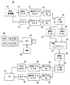
図1を参照して、この実施例のハードディスクビデオレコーダ10は、アナログ受信機12を含む。アナログ受信機12は、アンテナ(図示せず)から高周波テレビジョン信号を受け、所望のチャネルのコンポジットビデオ信号およびオーディオ信号を出力する。コンポジットビデオ信号はNTSCデコーダ14に与えられ、オーディオ信号はA/D変換器22に与えられる。
【0011】
NTSCデコーダ14は、与えられたコンポジットビデオ信号をデコードしてビデオデータを出力する。デコードされたビデオデータは、MPEGビデオエンコーダ16の符号化処理によってビデオESに変換され、変換されたビデオESは、パケット化回路26のパケット化処理によってビデオPESに変換される。一方、A/D変換器20は、オーディオ信号にA/D変換を施し、オーディオデータをMPEGオーディオエンコーダ22に与える。オーディオデータは、MPEGオーディオエンコーダ22の符号化によってオーディオESに変換され、オーディオESはパケット化回路24のパケット化によってオーディオPESに変換される。
【0012】
マルチプレクサ26は、パケット化回路18および24から出力されたビデオPESおよびオーディオPESを多重してMPEG−PSを生成するとともに、MPEG−PSに含まれるビデオフレームのインデックスデータを生成する。MPEG−PSおよびインデックスデータは、MPEGバッファ28およびINDEXバッファ30を介してHDD32に与えられる。HDD32は、MPEG−PSが格納されたMPEGファイルおよびインデックスデータが格納されたINDEXファイルをハードディスク34上に作成する。こうして、所望の番組の映像と音声とがハードディスク34に記録される。
【0013】
ハードディスク34に記録されたMPEGファイルからHDD32によってMPEG−PSが再生されると、当該MPEG−PSはMPEGバッファ36を介してデマルチプレクサ38に与えられる。デマルチプレクサ38は、与えられたMPEG−PSからビデオPESパケットおよびオーディオPESパケットを抽出し、ビデオPESパケットを非パケット化回路40に、オーディオPESパケットを非パケット化回路46にそれぞれ与える。非パケット化回路40および46はそれぞれ、ビデオPESおよびオーディオPESをビデオESおよびオーディオESに変換し、変換したビデオESおよびオーディオESをMPEGビデオデコーダ42およびMPEGオーディオデコーダ48に与える。
【0014】
MPEGビデオデコーダ42は、与えられたビデオESをデコードしてビデオデータを生成し、生成したビデオデータをNTSCエンコーダ44に与える。ビデオデータは、NTSCエンコーダ44によってコンポジットビデオ信号に変換され、変換されたコンポジットビデオ信号はテレビジョン受像機52に出力される。この結果、所望の番組の再生映像が、テレビジョン受像機52のモニタ画面に表示される。
【0015】
MPEGオーディオエンコーダ48は、与えられたオーディオESをデコードしてオーディオデータを生成する。生成されたオーディオデータはD/A変換器50によってアナログオーディオ信号に変換され、変換されたオーディオ信号はテレビジョン受像機52に出力される。この結果、所望の番組の再生音声が、テレビジョン受像機52のスピーカから出力される。
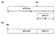
【0016】
MPEG−PSおよびインデックスデータは、図2に示すようなデータ構造を有する。図2によれば、MPEG−PSは複数のパックによって形成され、各々のパックにはパックヘッダ,システムヘッダ,ビデオPESパケットおよびオーディオPESパケットが含まれる。
【0017】
MPEGフォーマットでは、Iピクチャ,BピクチャおよびPピクチャの3つのフレームタイプが規定されており、1つのピクチャを形成するビデオPESパケットが異なるパックに跨ることはない。つまり、ある画面のIピクチャを形成する複数のビデオPESパケットは同じパックに含まれ、ある画面のBピクチャを形成する複数のビデオPESパケットは同じパックに含まれ、そしてある画面のPピクチャを形成する複数のビデオPESパケットは同じパックに含まれる。
【0018】
また、MPEG−PSを形成する最初のパックにのみシステムヘッダを付加すれば、MPEGフォーマットの条件は満たされる。しかし、この実施例のMPEGビデオエンコーダ24はVBR方式を採用しており、ビットレートはピクチャ毎に変動する。このため、いずれのパックにもシステムヘッダが割り当てられ、このシステムヘッダにビットレート情報が埋め込まれる。
【0019】
なお、オーディオPESパケットは、再生映像と再生音声との間で互いに同期がとられるように、ビデオPESパケットの間に間欠的に挿入される。
【0020】
インデックスデータは、各々のピクチャに24バイトずつ割り当てられる。この24バイトによって、対応するピクチャのフレームサイズ値,MPEG−PSの先頭からのオフセット値,フレームタイプおよび時間情報が表現される。
【0021】
この実施例のハードディスクビデオレコーダ10は、常時録画機能を有する。この機能をオン状態にすると、電源の投入と同時に番組録画が開始される。常時録画時にハードディスク34上に作成されるMPEGファイルおよびINDEXファイルには、それぞれ“RINGBUFF.mpg”および“RINGBUFF.ndx”のファイル名が割り当てられる。
【0022】
ただし、常時録画によって作成されるMPEGファイルのサイズは予め規定されており、取り込まれたMPEG−PSのサイズがこの規定サイズを超えると、先行するMPEG−PSは、後続のMPEG−PSによって上書きされる。つまり、MPEG−PSのサイズが規定サイズを超えた時点で、MPEGファイルはいわゆるリングファイルとなる。MPEGファイルがリングファイルとなると、INDEXファイルもまたリングファイルとなり、INDEXファイルに書き込まれたインデックスデータは、後続のインデックスデータによって上書きされる。
【0023】
常時録画が行われている途中で、操作パネル56に設けられた録画開始キー56cが操作されると、常時録画によって作成されたMPEGファイルとINDEXファイルとに終端揃え処理が施される。つまり、MPEGファイルに格納されたMPEG−PSの末尾フレームとINDEXデータに格納されたインデックスデータの末尾24ビットの対応関係が確保されるように、不足データがMPEGファイルまたはINDEXファイルに補充される。
【0024】
終端揃え処理が完了すると、MPEGファイルおよびINDEXファイルがクローズされ、各々のファイルのリング状態を特定するためのリング情報ファイルがハードディスク34上に作成される。リング情報ファイルには、ファイル名“RINGBUFF.loop”が割り当てられる。常時録画によって作成されたMPEGファイル,INDEXファイルおよびリング情報ファイルは、正規保存のためにファイル名の変更を施される。具体的には、MPEGファイルのファイル名が“RINGBUFF.mpg”から“SAN****.mpg”に変更され、INDEXファイルのファイル名が“RINGBUFF.ndx”から“SAN****.ndx”に変更され、そしてリング情報ファイルのファイル名が“RINGBUFF.loop”から“SAN****.loop”に変更される(****:ファイル番号)。ファイル名の変更によって、MPEGファイル,INDEXファイルおよびリング情報ファイルの各々は、テンポラリファイルから正規ファイルに変化する。
【0025】
ファイル名の変更が完了すると、正規録画が開始される。正規録画によって作成されるMPEGファイルおよびINDEXファイルには、正規ファイル名である“SAN****.mpg”および“SAN****.ndx”が割り当てられる。なお、正規録画によって作成されるMPEGファイルおよびINDEXファイルにおいては、MPEG−PSおよびインデックスデータがリング状に上書きされることはない。
【0026】
正規録画が開始された後に操作パネル56の録画停止キー56dが操作されると、正規録画によって作成されたMPEGファイルおよびINDEXファイルについて上述と同様の終端揃え処理が実行され、その後、当該MPEGファイルおよびインデックスファイルがクローズされる。ファイルクローズが完了すると、録画モードは正規録画から常時録画に移行する。
【0027】
なお、常時録画または正規録画の途中で、操作パネル56に設けられたメニューキー56aによって任意のMPEGファイルが選択され、かつ再生キー56bが操作されると、当該MPEGファイルが録画処理と並行して再生される。
【0028】
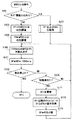
CPU54は、電源の投入によってシステム全体が起動したとき、ROM58に記憶された制御プログラムに基づいて、図3〜図10に示すフロー図を処理する。なお、システム全体の起動によって、マルチプレクサ26からMPEG−PSおよびインデックスデータが出力され、MPEG−PSはMPEGバッファ28に、インデックスデータはINDEXバッファ30に、それぞれ蓄積されていく。
【0029】
図3に示すステップS1では、常時録画用のファイルを作成するとともに、作成されたファイルをオープンする。具体的には、ファイル名が“RINGBUFF.mpg”のMPEGファイルとファイル名が“RINGBUFF.ndx”のINDEXファイルとをハードディスク34上に新規に作成し、作成したMPEGファイルおよびINDEXファイルをオープンする。
【0030】
続くステップS3では、常時録画用の変数を設定する。具体的には、MPEGファイルに関して、書込位置を示す変数WPm,MPEGファイルの上書き回数(リング回数)を示す変数RNGm,および記録されたMPEG−PSのサイズを示す変数RMSを“0”に設定し、ファイルサイズを示す変数FSmを所定値TRSに設定し、そしてMPEG−PSの1回あたりの書き込みサイズを示す変数MSを128Kバイトに設定する。また、INDEXファイルについて、書込位置を示す変数WPi,上書き回数を示す変数RNGi,およびファイルサイズを示す変数FSiを“0”に設定する。
【0031】
なお、変数RMSは、詳しくは、MPEGファイルに記録されたMPEG−PSの積算値である。したがって、数値は、書き込みに伴って増加し続け、MPEGファイルの上書きによって減少することはない。
【0032】
ステップS5ではMPEGファイル録画を行い、ステップS7ではINDEXファイル録画を行う。これによって、MPEGバッファ28に蓄積されたMPEG−PSおよびINDEXバッファ30に蓄積されたインデックスデータがHDD32に与えられ、ステップS1で作成されたMPEGファイルおよびINDEXファイルにそれぞれ書き込まれる。また、MPEG−PSの書き込みに伴って、変数WPmおよびRMSが更新され、かつ必要に応じて変数RNGmが更新される。さらに、インデックスデータの書き込みに伴って、変数WPiが更新され、かつ必要に応じて変数RNGiおよびFSiが更新される。
【0033】
ステップS9では、オペレータによって任意に選択されたMPEGファイルの再生を行う。ここで、選択可能なMPEGファイルには、現時点で常時録画が行われているMPEGファイルも含まれる。ステップS11では録画開始キー56cの操作の有無を判別し、NOであればステップS5〜S9の処理を繰り返すが、YESであればステップS13〜S27で終端揃え処理を実行する。
【0034】
まずステップS13でINDEXファイルに格納された最新24バイトのインデックスデータからオフセット値およびフレームサイズ値を取得する。この最新24バイトは、変数WPiに先行する24バイトである。また、取得されるオフセット値は、取り込まれたMPEG−PSの先頭から最新24バイトのインデックスデータに対応するピクチャの先頭までの距離であり、取得されるフレームサイズ値は、最新24バイトのインデックスデータに対応するピクチャのサイズである。ステップS15ではこのようなオフセット値およびフレームサイズ値を加算して加算値CRMSを求め、ステップS17およびS19では加算値CRMSを変数RMSと比較する。
【0035】
変数RMSはMPEGファイルに記録されたMPEG−PSの積算値であり、MPEGファイルに書き込まれた最終フレームとINDEXファイルに書き込まれた最新24バイトのインデックスデータとの対応関係が確保されると、加算値CRMSと変数RMSとが互いに一致する。換言すれば、変数RMSが加算値CRMSを下回るときは図16(A)に示すようにMPEG−PSが不足し、変数RMSが加算値CRMSを上回るときは図16(B)に示すようにインデックスデータが不足する。
【0036】
このため、RMS>CRMSの条件が成立すれば、ステップS19でNOと判断し、ステップS21でINDEXファイル録画を実行する。ステップS21の処理が完了すると、ステップS13に戻る。
【0037】
一方、RMS<CRMSの条件が成立すれば、ステップS19でYESと判断し、ステップS23で加算値CRMSと変数RMSとの差分値“CRMS−RMS”が128Kバイト未満であるかどうか判断する。そして、128Kバイト以上であればそのままステップS27に進むが、128Kバイト未満であれば、ステップS25で変数MSを差分値“CRMS−RMS”に更新してからステップS27に進む。ステップS27ではMPEGファイル録画処理を行い、処理が完了するとステップS17に戻る。
【0038】
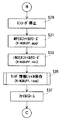
かかる処理によって不足データが補充され、変数RMSが加算値CRMSと一致すると、ステップS17からステップS29に進み、図1に示すMPEGビデオエンコーダ16およびMPEGオーディオエンコーダ22を停止する。この停止処理の結果、マルチプレクサ26からのMPEG−PSの出力が中断される。
【0039】
ステップS31およびS33では常時録画用のMPEGファイルおよびINDEXファイルをクローズする。ステップS35では、MPEGファイルおよびINDEXファイルがリングファイルである場合に、上述の変数FSm,WPm,RNGm,FSi,WPiおよびRNGiが格納されたリング情報ファイルを作成する。作成されたリング情報ファイルには“RINGBUFF.loop”のファイル名が割り当てられ、このリング情報ファイルはハードディスク34に保存される。
【0040】
ステップS37では、常時録画用のMPEGファイルおよびINDEXファイルについて、ファイル名を“RINGBUFF.mpg”から“SAN****.mpg”に変更するとともに、“RINGBUFF.ndx”から“SAN****.ndx”に変更する。さらに、リング情報ファイルが作成されたときは、当該リング情報ファイルのファイル名を“RINGBUFF.loop”から“SAN****.loop”に変更する。常時録画によって得られたMPEGファイル,INDEXファイルおよびリング情報ファイルは、ファイル名の変更によってハードディスク34に正規に保存されることとなる。
【0041】
ステップS39では正規録画用のファイルを作成し、かつ作成されたファイルをオープンする。具体的には、ファイル名が“SAN****.mpg”のMPEGファイルとファイル名が“SAN****.ndx”のINDEXファイルとをハードディスク34上に新規に作成し、作成したMPEGファイルおよびINDEXファイルをオープンする。なお、新規に作成されたMPEGファイルおよびINDEXファイルのファイル名には、新規のファイル番号が割り当てられる。
【0042】
続くステップS41では、正規録画用の変数を設定する。具体的には、MPEGファイルに関して、変数WPm,RNGmおよびRMSを“0”に設定し、変数FSmを所定値RRSに設定し、そして変数MSを128Kバイトに設定する。また、INDEXファイルについて、変数WPiおよびRNGiを“0”に設定する。
【0043】
ステップS3における変数設定と異なるのは、所定値TRSに代えて所定値RRSが変数FSmとして設定される点、およびINDEXファイルのサイズを示す変数FSiが不定とされる点である。なお、所定値RRSは所定値TRSよりも格段に大きく、正規録画用のMPEGファイルがリングファイルとなることはない。
【0044】
ステップS43〜S47では、上述のステップS5〜S9と同様の処理を実行する。ただし、ステップS43におけるMPEG−PSの書き込み先およびステップS45におけるインデックスデータの書き込み先は、ステップS39で作成されたMPEGファイルおよびINDEXファイルである。
【0045】
ステップS49では録画停止キー56dの操作の有無を判別し、NOであればステップS43〜S47の処理を繰り返す。これに対して、YESと判断されれば、ステップS51〜S65で終端揃え処理を実行する。ただし、ステップS51〜S65の処理は、不足データの書き込み先が正規録画用のMPEGファイルまたはINDEXファイルである点を除き、上述のステップS13〜S27と同様であるため、重複した説明は省略する。
【0046】
終端揃え処理が完了すると、ステップS67およびS69で正規録画用のMPEGファイルおよびINDEXファイルをクローズし、常時録画を再開すべくステップS1に戻る。
【0047】
なお、前回の常時録画によって作成されたMPEGファイルおよびINDEXファイルはファイル名の変更によって正規に保存されたため、今回の常時録画用のMPEGファイルおよびINDEXファイルはステップS1で新規に作成される。
【0048】
図3に示すステップS5または図6に示すステップS43のMPEGファイル録画処理は、図8に示すフロー図に従う。まずステップS71でMPEGバッファ30に蓄積されたMPEG−PSのサイズを変数MSと比較し、当該サイズが変数MS以上となったときにYESと判断する。ステップS73およびS91では、変数MSおよびWPmの加算値を変数FSmと比較する。具体的には、WPm+MS>FSmの条件が成立するかどうかをステップS73で判別し、WPm+MS=FSmの条件が成立するかどうかをステップS91で判別する。
【0049】
図13(A)に示すように、変数MSに相当するサイズのMPEG−PSをMPEGファイルの変数WPmに対応する位置以降に格納できないとき、WPm+MS>FSmの条件が成立する。このときは、図8に示すステップS73からステップS75に進み、変数WPmに対応する位置から末尾位置までのファイルサイズTSm(=FSm−WPm)を算出する。ステップS77では算出されたサイズTSmに相当するMPEG−PSをMPEGファイルの変数WPmに対応する位置以降に書き込み、ステップS79では変数RMSに変数TSmを加算し、そしてステップS81では変数WPmを“0”に設定する。MPEGファイルの記録状態および変数WPmの位置は、図13(A)から図13(B)に遷移する。
【0050】
ステップS83では変数RNGmをインクリメントし、ステップS85では“MS−TSm”に相当するサイズのMPEG−PSをMPEGファイルに書き込む。変数WPmは“0”であるため、当該MPEG−PSはMPEGファイルの先頭から上書きされる。ステップS87では変数RMSに“MS−TSm”を加算し、ステップS89では変数WPmに“MS−TSm”を加算する。MPEGファイルの記録状態および変数WPmの位置は、図13(B)から図13(C)に遷移する。ステップS89の処理が完了すると、上階層のルーチンに復帰する。
【0051】
図14(A)に示すように、変数MSに相当するサイズが変数WPmに対応するファイル位置からファイル末尾までの容量に等しいとき、WPm+MS=FSmの条件が成立する。このときは、図8に示すステップS91からステップS93に進み、変数MSに相当するサイズのMPEG−PSをMPEGファイルの変数WPmに対応する位置以降に書き込む。ステップS95では変数RMSに変数MSを加算し、ステップS97では変数WPmを“0”とし、そしてステップS99では変数RNGmをインクリメントする。MPEGファイルの記録状態および変数WPiの位置は、図14(A)から図14(B)に遷移する。ステップS99の処理が完了すると、上階層のルーチンに復帰する。
【0052】
図15(A)に示すように、変数MSに相当するサイズが変数WPmに対応するファイル位置からファイル末尾までの容量よりも小さいときは、WPm+MS>FSmおよびWPm+MS=FSmのいずれの条件も成立しない。このときはステップS91でNOと判断し、ステップS101およびS103でステップS93およびS95と同様の処理を実行し、ステップS105で変数WPmに変数MSを加算する。MPEGファイルの記録状態は、図15(A)から図15(B)に遷移する。ステップS105の処理が完了すると、上階層のルーチンに復帰する。
【0053】
なお、所定値RRSは、上述のように所定値TRSよりも格段に大きい。このため、図6に示すステップS43から図8に示すサブルーチンに移行したときは、ステップS101〜S105が常に実行され、変数RNGmが更新されることはない。
【0054】
図3に示すステップS7または図6に示すステップS45のINDEXファイル録画処理は、図9に示すサブルーチンに従う。まずステップS111およびS113で変数RNGmの値を判別する。変数RNGmが“0”であれば、ステップS141に進み、INDEXバッファ30に蓄積されたインデックスデータのサイズISを取得し、ステップS143で当該サイズISに相当するインデックスデータをINDEXファイルの変数WPiに対応する位置以降に書き込み、そしてステップS145で変数WPiにサイズISを加算する。ステップS145の処理が完了すると、上階層のルーチンに復帰する。
【0055】
変数RNGmが“1”であれば、ステップS113でYESと判断し、ステップS115における変数FSiの更新処理を経てステップS117に進む。変数RNGmが“2”以上であれば、ステップS113からステップS117に移行する。
【0056】
ステップS115では、具体的には、“WPi+360バイト”を変数FPiとして設定する。変数RNGmが“1”を示すのは、MPEGファイルが1回目の上書きを施されるときであり、このとき、INDEXファイルのサイズを“WPi+360バイト”に規定する。1フレームに相当するインデックスデータのサイズは24バイトであるため、ステップS115の処理によって、現時点の変数WPiに15フレーム(=1GOP)分のマージンを加算したサイズが、INDEXファイルのサイズとなる。
【0057】
ステップS117以降では、上述のMPEG録画処理と同様の処理を行う。具体的には、ステップS119でWPi+IS>FSiの条件が成り立つかどうか判断し、ステップS133でWPi+IS=FSiの条件が成り立つかどうか判断し、各々の判断結果に応じて異なるステップに進む。
【0058】
ステップS119でYESと判断されると、ステップS121で変数WPiに対応する位置から末尾位置までのファイルサイズTSi(=FSi−WPi)を算出する。ステップS123では算出されたサイズTSiに相当するインデックスデータをINDEXファイルの変数WPiに対応する位置以降に書き込み、ステップS125では変数WPiを“0”に設定する。ステップS127では変数RNGiをインクリメントし、ステップS129では“IS−TSi”に相当するサイズのインデックスデータをINDEXファイルに書き込む。変数WPiは“0”であるため、当該インデックスデータはINDEXファイルの先頭から上書きされる。ステップS131では変数WPiに“IS−TSi”を加算し、その後上階層のルーチンに復帰する。
【0059】
ステップS133でYESと判断されるとステップS135に進み、変数ISに相当するサイズのインデックスデータをINDEXファイルの変数WPiに対応する位置以降に書き込む。ステップS137では変数WPiを“0”とし、ステップS139では変数RNGmをインクリメントする。ステップS139の処理が完了すると、上階層のルーチンに復帰する。
【0060】
ステップS133でNOと判断されると、ステップS143で変数ISに相当するサイズのインデックスデータをINDEXファイルの変数WPiに対応する位置以降に書き込む。その後、ステップS145で変数WPiにサイズISを加算し、上階層のルーチンに復帰する。
【0061】
なお、所定値RRSは所定値TRSよりも格段に大きく、変数RNGmが“0”以外の値をとることはないため、図6に示すステップS45から図9に示すサブルーチンに移行したときは、ステップS141〜S145の処理が常に実行される。
【0062】
図5に示すステップS35のリング情報ファイル保存処理は、図10に示すサブルーチンに従う。まずステップS151で変数RNGmを“0”と比較し、RNGm=0であれば、リング情報ファイルを作成することなく、上階層のルーチンに復帰する。一方、RNGm>0であれば、ステップS153に進み、ファイル名が“RINGBUFF.loop”のリング情報ファイルを作成し、かつ当該リング情報ファイルをオープンする。
【0063】
ステップS155ではMPEGファイルに関連する変数FSm,WPmおよびRNGmをリング情報ファイルに書き込み、ステップS157ではINDEXファイルに関連する変数FSi,WPiおよびRNGiを同じリング情報ファイルに書き込む。変数書き込みが完了すると、ステップS159でリング情報ファイルをクローズし、上階層のルーチンに復帰する。
【0064】
図3に示すステップS9または図6に示すステップS47のMPEGファイル再生処理において、正規に保存されたMPEGファイルつまり“SAN****.mpg”が選択された場合、CPU54は図11に示すサブルーチンを実行する。
【0065】
まずステップS161で、所望のMPEGファイルに対応するリング情報ファイルがハードディスク34上に存在するかどうか判断する。ここでNOであればステップS163に進み、所望のMPEGファイルに対応するINDEXファイルの先頭値をインデックスデータの読み出し位置を示す変数RPiとして設定する。続くステップS165では、所望のMPEGファイルの先頭値をMPEG−Sの読み出し位置を示す変数RPmとして設定する。
【0066】
一方、ステップS161でYESと判断されたときは、ステップS167で図12に示すサブルーチンを処理し、変数RPiおよびRPmを決定する。
【0067】
ステップS169では、HDD32を通してハードディスク34にアクセスし、所望のMPEGファイルの変数RPmに対応する位置から128KバイトのMPEG−PSを読み出す。読み出されたMPEG−PSは、MPEGバッファ36に蓄積され、再生処理を施される。ステップS171では、変数RPmに128Kバイトを加算し、ステップS173およびS175ではキー操作の有無をそれぞれ判断する。具体的には、再生停止キー56eの操作の有無をステップS173で判別し、特殊再生キー56fの操作の有無をステップS175で判別する。
【0068】
再生停止キー56eおよび特殊再生キー56fのいずれも操作されなかったときは、そのままステップS169に戻る。この結果、連続する再生映像および再生音声がテレビジョン受像機52から出力される。
【0069】
再生停止キー56eが操作されたときは、ステップS173でYESと判断し、上階層のルーチンに復帰する。
【0070】
特殊再生キー56fが操作されたときは、ステップS177で変数RPiを更新し、ステップS178で更新後の変数RPiが示す位置以降の24バイトのインデックスデータからオフセット値を取得する。ステップS179では取得したオフセット値を変数RPmとして設定し、設定が完了するとステップS169に戻る。この結果、早送り映像,巻き戻し映像,スチル映像などの特殊映像がテレビジョン受像機52から出力される。
【0071】
ステップS167から図12に示すサブルーチンに移行すると、まずステップS181でリング情報ファイルをオープンする。ステップS183では、オープンされたリング情報ファイルに含まれる変数WPmおよびWPiを変数RPmおよびRPiとして設定する。ステップS185では、所望のMPEGファイルに対応するINDEXファイルを特定し、当該INDEXファイルの変数RPmに対応する位置以降の24バイトからオフセット値およびフレームタイプを取得する。
【0072】
ステップS187では、リング情報ファイルに含まれる変数FSmおよびRNGmとステップS183で設定された変数RPmとステップS185で取得されたオフセット値との間で、数1に示す条件が満足されるかどうかを判断する。
【0073】
【数1】
オフセット値≧RPm+FSm*RNGm
変数FSmは所望のMPEGファイルのサイズを示し、変数RNGmは所望のMPEGファイルの上書き回数を示し、そして変数RPm(=WPm)は所望のMPEGファイルの書込終了位置の次のバイトを示す。これらの変数はいずれもMPEGファイルの実際の記録状態を表す変数であり、“RPm+FSm*RNGm”は、上書きされることなくMPEGファイルに残っているMPEG−PSの先頭位置を示す。
【0074】
一方、オフセット値は、INDEXファイルから取得した情報である。MPEGファイルおよびINDEXファイルのいずれもリングファイルであること、およびMPEG−PSのビットレートが可変であることを考慮すると、ステップS165で取得されたオフセット値から始まるフレームが後続のMPEG−PSによって上書きされている可能性がある。
【0075】
そこで、取得されたオフセット値から始まるフレームがMPEGファイルに残っているかどうかをステップS187で判別するようにしている。
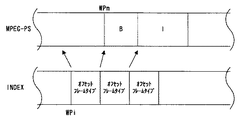
【0076】
図17に示す記録状態では、変数WPi以降の24バイトから取得されたオフセット値に対応するフレームが、上書きによって消失している。このときは数1の条件が満たされず、ステップS187でNOと判断される。
【0077】
ステップS187でNOと判断されると、ステップS191で変数RPiに24バイトを加算してからステップS185に戻る。ステップS185では、更新された変数RPi以降の24バイトからオフセット値およびフレームタイプを取得し、続くステップS187では、新規に取得したオフセット値およびフレームタイプを用いて、数1の条件が満たされるかどうかを判断する。
【0078】
図17の記録状態では、更新された変数RPi(=WPi+24バイト)以降の24バイトから取得されたオフセット値に対応するフレームがMPEGファイル上に存在する。このときは数1の条件が満たされ、ステップS187でYESと判断される。
【0079】
ステップS187でYESと判断されると、直前のステップS185で取得されたフレームタイプを判別する。そして、フレームタイプが“I”でなければ、ステップS191で変数RPiを更新してからステップS185〜S189の処理を再度実行する。
【0080】
図17の記録状態では、再度更新された変数RPi(=WPi+48バイト)以降の24バイトから取得されたオフセット値に対応するフレームが、Iピクチャである。このため、2回目のステップS189の処理では、YESと判断される。
【0081】
ステップS189でYESと判断されるとステップS193に進み、直前のステップS185で取得されたオフセット値を変数RPmとして設定する。設定が完了すると、ステップS195でリング情報ファイルをクローズしてから上階層のルーチンに復帰する。
【0082】
以上の説明から分かるように、MPEGファイルには、Iピクチャが間欠的に挿入されたMPEG−PSが循環的に書き込まれる。また、INDEXファイルには、少なくともIピクチャを特定できるインデックスデータが循環的に書き込まれる。CPU54は、INDEXファイルに格納されたインデックスデータに基づいてMPEG−PSの先頭部分からIピクチャを検出し、検出したIピクチャからMPEG−PSを再生する。このように、INDEXファイルに格納されたインデックスデータに基づいてMPEG−PSの先頭部分からIピクチャを特定するようにしたため、書き込みが循環的に行われるMPEGファイルに格納されたMPEG−PSを先頭部分から再生することができる。
【0083】
また、終端部分においては、終端揃え処理によってMPEG−PSとインデックスデータとの対応関係が確保されるため、MPEG−PSの終端部分から特殊再生を開始することができる。
【図面の簡単な説明】
【図1】この発明の一実施例を示すブロック図である。
【図2】インデックスデータおよびMPEG−PSのデータ構造の一例を示す図解図である。
【図3】図1実施例の動作の一部を示すフロー図である。
【図4】図1実施例の動作の他の一部を示すフロー図である。
【図5】図1実施例の動作のその他の一部を示すフロー図である。
【図6】図1実施例の動作のさらにその他の一部を示すフロー図である。
【図7】図1実施例の動作の他の一部を示すフロー図である。
【図8】図1実施例の動作のその他の一部を示すフロー図である。
【図9】図1実施例の動作のさらにその他の一部を示すフロー図である。
【図10】図1実施例の動作の他の一部を示すフロー図である。
【図11】図1実施例の動作のその他の一部を示すフロー図である。
【図12】図1実施例の動作のさらにその他の一部を示すフロー図である。
【図13】図1実施例の動作の一部を示す図解図である。
【図14】図1実施例の動作の他の一部を示す図解図である。
【図15】図1実施例の動作のその他の一部を示す図解図である。
【図16】図1実施例の動作のさらにその他の一部を示す図解図である。
【図17】図1実施例の動作の他の一部を示す図解図である。
【符号の説明】
10…ハードディスクビデオレコーダ
16…MPEGビデオエンコーダ
22…MPEGオーディオエンコーダ
26…マルチプレクサ
28,36…MPEGバッファ
30…INDEXバッファ
32…HDD
42…MPEGビデオデコーダ
48…MPEGオーディオデコーダ[0001]
BACKGROUND OF THE INVENTION
The present invention relates to a content recording apparatus, and in particular, is applied to, for example, a hard disk video recorder, and video content that is cyclically recorded in a first file and whose reference screen is defined intermittently is cyclically recorded in a second file. The present invention also relates to a content playback apparatus that plays back based on the index information of the reference screen.
[0002]
[Prior art]
In a conventional hard disk recorder of this type, a received program video signal and program audio signal are encoded into a video ES and an audio ES (ES: Elementary Stream) according to the MPEG format, and the video ES and the audio ES are converted into a video PES and an audio ES by packetization. Audio PES (PES: Packetized Elementary Stream) is converted. When MPEG-PS (PS: Program Stream) is generated by multiplexing video PES and audio PES, an MPEG file including the MPEG-PS is recorded on the hard disk. Also, index information (frame size, frame type, offset from the beginning, time stamp) of each picture is created so that the I picture, B picture, and P picture that form the video ES can be specified. The included index file is recorded on the hard disk.
[0003]
[Problems to be solved by the invention]
However, when the MPEG format adopts the VBR system (VBR: Variable Bit Rate), the data size of the MPEG-PS varies depending on the nature of the program video. On the other hand, the data size of the index information is fixed. Accordingly, when the file sizes of the MPEG file and the index file are defined in advance and the MPEG-PS and index information are updated in a ring shape within the MPEG file and the index file, the top of the MPEG-PS and the top of the index information May not be compatible with each other, and there is a possibility that the MPEG-PS cannot be reproduced from the beginning.
[0004]
Therefore, a main object of the present invention is to provide a content reproduction apparatus capable of reproducing video content stored in a file from the beginning.
[0005]
[Means for Solving the Problems]
This inventionContent playback deviceIs a content playback device that plays back video content that is cyclically written to the first file and whose reference screen is intermittently defined based on the index information of the reference screen that is cyclically written to the second file. Specific means for specifying the reference screen from the head portion of the video content based on the index information, and reproduction means for reproducing the video content from the reference screen specified by the specification means, The index information includes an offset value from the beginning of the video content to each reference screen, the specifying means includes a leading position detecting means for detecting the leading position of the video content remaining in the first file, and an offset value from the second file. An offset value detecting means for detecting, and a reference screen specifying means for specifying the reference screen based on the head position detected by the head position detecting means and the offset value detected by the offset detecting means.It is characterized byThe
[0006]
[Action]
In the first file, video content in which the reference screen is intermittently defined is cyclically written. Further, the index information of the reference screen is cyclically written in the second file. The specifying unit specifies the reference screen from the head portion of the video content based on the index information of the second file, and the playback unit plays the video content from the specified reference screen.
[0007]
The index information preferably includes an offset value from the beginning of the video content to each reference screen. At this time, the specifying means detects the start position of the video content remaining in the first file, detects the offset value from the second file, and based on the detected start position and offset value, the start portion of the video content The reference screen is specified from the above.
[0008]
【The invention's effect】
According to the present invention, since the reference screen is specified from the head portion of the video content based on the index information of the second file, the video content stored in the first file in which writing is performed cyclically is started from the head portion. Can be played.
[0009]
The above object, other objects, features and advantages of the present invention will become more apparent from the following detailed description of embodiments with reference to the drawings.
[0010]
【Example】
Referring to FIG. 1, the hard
[0011]
The
[0012]
The
[0013]
When the MPEG-PS is reproduced from the MPEG file recorded on the
[0014]
The MPEG
[0015]
The
[0016]
MPEG-PS and index data have a data structure as shown in FIG. According to FIG. 2, the MPEG-PS is formed by a plurality of packs, and each pack includes a pack header, a system header, a video PES packet, and an audio PES packet.
[0017]
In the MPEG format, three frame types of I picture, B picture, and P picture are defined, and video PES packets forming one picture do not straddle different packs. That is, a plurality of video PES packets forming an I picture of a screen are included in the same pack, a plurality of video PES packets forming a B picture of a screen are included in the same pack, and a P picture of a screen is formed. A plurality of video PES packets to be included in the same pack.
[0018]
Also, if the system header is added only to the first pack forming the MPEG-PS, the MPEG format condition is satisfied. However, the
[0019]
The audio PES packet is intermittently inserted between the video PES packets so that the reproduced video and the reproduced audio are synchronized with each other.
[0020]
The index data is assigned 24 bytes to each picture. These 24 bytes represent the frame size value of the corresponding picture, the offset value from the beginning of the MPEG-PS, the frame type, and time information.
[0021]
The hard
[0022]
However, the size of the MPEG file created by continuous recording is specified in advance, and if the size of the imported MPEG-PS exceeds this specified size, the preceding MPEG-PS is overwritten by the subsequent MPEG-PS. The That is, when the MPEG-PS size exceeds the specified size, the MPEG file becomes a so-called ring file. When the MPEG file becomes a ring file, the INDEX file also becomes a ring file, and the index data written in the INDEX file is overwritten by subsequent index data.
[0023]
When the recording start key 56c provided on the
[0024]
When the end alignment process is completed, the MPEG file and the INDEX file are closed, and a ring information file for specifying the ring state of each file is created on the
[0025]
When the file name change is completed, regular recording is started. The regular file names “SAN ****. Mpg” and “SAN ****. Ndx” are assigned to the MPEG file and the INDEX file created by the regular recording. Note that MPEG-PS and index data are not overwritten in a ring shape in MPEG files and INDEX files created by regular recording.
[0026]
When the recording stop key 56d of the
[0027]
When an arbitrary MPEG file is selected by the menu key 56a provided on the
[0028]
The
[0029]
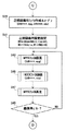
In step S1 shown in FIG. 3, a file for continuous recording is created and the created file is opened. Specifically, an MPEG file with the file name “RINGBUFF.mpg” and an INDEX file with the file name “RINGBUFF.ndx” are newly created on the
[0030]
In the subsequent step S3, a variable for constant recording is set. Specifically, for the MPEG file, a variable WPm indicating the writing position, a variable RNGm indicating the number of overwrites (ring times) of the MPEG file, and a variable RMS indicating the size of the recorded MPEG-PS are set to “0”. Then, a variable FSm indicating the file size is set to a predetermined value TRS, and a variable MS indicating the writing size per MPEG-PS is set to 128 Kbytes. For the INDEX file, a variable WPi indicating the writing position, a variable RNGi indicating the number of overwrites, and a variable FSi indicating the file size are set to “0”.
[0031]
The variable RMS is an integrated value of MPEG-PS recorded in the MPEG file in detail. Therefore, the numerical value continues to increase with writing and does not decrease due to overwriting of the MPEG file.
[0032]
In step S5, MPEG file recording is performed, and in step S7, INDEX file recording is performed. As a result, the MPEG-PS stored in the
[0033]
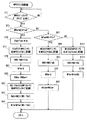
In step S9, the MPEG file arbitrarily selected by the operator is reproduced. Here, the selectable MPEG file includes an MPEG file which is always recorded at the present time. In step S11, it is determined whether or not the recording start key 56c has been operated. If NO, the processing in steps S5 to S9 is repeated. If YES, end alignment processing is executed in steps S13 to S27.
[0034]
First, in step S13, an offset value and a frame size value are acquired from the latest 24-byte index data stored in the INDEX file. The latest 24 bytes are the 24 bytes preceding the variable WPi. The acquired offset value is the distance from the start of the captured MPEG-PS to the start of the picture corresponding to the latest 24-byte index data, and the acquired frame size value is the latest 24-byte index data. Is the size of the picture corresponding to. In step S15, such an offset value and a frame size value are added to obtain an added value CRMS, and in steps S17 and S19, the added value CRMS is compared with the variable RMS.
[0035]
The variable RMS is an integrated value of MPEG-PS recorded in the MPEG file, and is added when the correspondence between the last frame written in the MPEG file and the latest 24-byte index data written in the INDEX file is secured. The value CRMS and the variable RMS match each other. In other words, when the variable RMS is lower than the added value CRMS, MPEG-PS is insufficient as shown in FIG. 16A, and when the variable RMS is higher than the added value CRMS, the index is set as shown in FIG. Insufficient data.
[0036]
Therefore, if the condition of RMS> CRMS is satisfied, NO is determined in step S19, and INDEX file recording is executed in step S21. When the process of step S21 is completed, the process returns to step S13.
[0037]
On the other hand, if the condition RMS <CRMS is satisfied, YES is determined in step S19, and it is determined in step S23 whether the difference value “CRMS−RMS” between the added value CRMS and the variable RMS is less than 128 Kbytes. If it is 128 Kbytes or more, the process proceeds directly to step S27. If it is less than 128 Kbytes, the variable MS is updated to the difference value “CRMS-RMS” in step S25, and then the process proceeds to step S27. In step S27, an MPEG file recording process is performed. When the process is completed, the process returns to step S17.
[0038]
When the deficient data is replenished by such processing and the variable RMS matches the added value CRMS, the process proceeds from step S17 to step S29, and the
[0039]
In steps S31 and S33, the MPEG file and INDEX file for continuous recording are closed. In step S35, when the MPEG file and the INDEX file are ring files, a ring information file storing the above-described variables FSm, WPm, RNGm, FSi, WPi, and RNGi is created. A file name “RINGBUFF.loop” is assigned to the created ring information file, and this ring information file is stored in the
[0040]
In step S37, the file name is changed from “RINGBUFF.mpg” to “SAN ****. Mpg” for the MPEG and INDEX files for continuous recording, and from “RINGBUFF.ndx” to “SAN ****”. Change to “.ndx”. Further, when the ring information file is created, the file name of the ring information file is changed from “RINGBUFF.loop” to “SAN ****. Loop”. The MPEG file, the INDEX file, and the ring information file obtained by regular recording are properly stored in the
[0041]
In step S39, a file for regular recording is created and the created file is opened. Specifically, an MPEG file with a file name “SAN ****. Mpg” and an INDEX file with a file name “SAN ****. Ndx” are newly created on the
[0042]
In a succeeding step S41, variables for regular recording are set. Specifically, for the MPEG file, variables WPm, RNGm, and RMS are set to “0”, variable FSm is set to a predetermined value RRS, and variable MS is set to 128 Kbytes. For the INDEX file, variables WPi and RNGi are set to “0”.
[0043]
The difference from the variable setting in step S3 is that the predetermined value RRS is set as the variable FSm instead of the predetermined value TRS, and the variable FSi indicating the size of the INDEX file is indefinite. Note that the predetermined value RRS is much larger than the predetermined value TRS, and the normal recording MPEG file does not become a ring file.
[0044]
In steps S43 to S47, processing similar to that in steps S5 to S9 described above is executed. However, the MPEG-PS write destination in step S43 and the index data write destination in step S45 are the MPEG file and INDEX file created in step S39.
[0045]
In step S49, it is determined whether or not the recording stop key 56d is operated. If NO, the processes in steps S43 to S47 are repeated. On the other hand, if YES is determined, termination alignment processing is executed in steps S51 to S65. However, the processing in steps S51 to S65 is the same as that in steps S13 to S27 described above except that the destination of the deficient data is an MPEG file or an INDEX file for regular recording, and thus a duplicate description is omitted.
[0046]
When the end alignment process is completed, the normal recording MPEG file and the INDEX file are closed in steps S67 and S69, and the process returns to step S1 to resume normal recording.
[0047]
Since the MPEG file and the INDEX file created by the previous continuous recording are properly stored by changing the file name, the current continuous recording MPEG file and the INDEX file are newly created in step S1.
[0048]
The MPEG file recording process in step S5 shown in FIG. 3 or step S43 shown in FIG. 6 follows the flowchart shown in FIG. First, in step S71, the size of the MPEG-PS stored in the
[0049]
As shown in FIG. 13A, when MPEG-PS having a size corresponding to the variable MS cannot be stored after the position corresponding to the variable WPm of the MPEG file, the condition of WPm + MS> FSm is satisfied. At this time, the process proceeds from step S73 shown in FIG. 8 to step S75, and the file size TSm (= FSm−WPm) from the position corresponding to the variable WPm to the end position is calculated. In step S77, MPEG-PS corresponding to the calculated size TSm is written after the position corresponding to the variable WPm of the MPEG file. In step S79, the variable TSm is added to the variable RMS. In step S81, the variable WPm is set to “0”. Set to. The recording state of the MPEG file and the position of the variable WPm transition from FIG. 13 (A) to FIG. 13 (B).
[0050]
In step S83, the variable RNGm is incremented, and in step S85, MPEG-PS having a size corresponding to “MS-TSm” is written into the MPEG file. Since the variable WPm is “0”, the MPEG-PS is overwritten from the top of the MPEG file. In step S87, “MS-TSm” is added to the variable RMS, and in step S89, “MS-TSm” is added to the variable WPm. The recording state of the MPEG file and the position of the variable WPm transition from FIG. 13 (B) to FIG. 13 (C). When the process of step S89 is completed, the process returns to the upper-level routine.
[0051]
As shown in FIG. 14A, when the size corresponding to the variable MS is equal to the capacity from the file position corresponding to the variable WPm to the end of the file, the condition of WPm + MS = FSm is satisfied. At this time, the process proceeds from step S91 shown in FIG. 8 to step S93, and the MPEG-PS having the size corresponding to the variable MS is written after the position corresponding to the variable WPm of the MPEG file. In step S95, the variable MS is added to the variable RMS. In step S97, the variable WPm is set to “0”. In step S99, the variable RNGm is incremented. The recording state of the MPEG file and the position of the variable WPi transition from FIG. 14 (A) to FIG. 14 (B). When the process of step S99 is completed, the process returns to the upper layer routine.
[0052]
As shown in FIG. 15A, when the size corresponding to the variable MS is smaller than the capacity from the file position corresponding to the variable WPm to the end of the file, neither of the conditions of WPm + MS> FSm and WPm + MS = FSm is satisfied. . At this time, NO is determined in step S91, processing similar to that in steps S93 and S95 is executed in steps S101 and S103, and variable MS is added to variable WPm in step S105. The recording state of the MPEG file transitions from FIG. 15 (A) to FIG. 15 (B). When the process of step S105 is completed, the process returns to the upper layer routine.
[0053]
Note that the predetermined value RRS is much larger than the predetermined value TRS as described above. Therefore, when the process proceeds from step S43 shown in FIG. 6 to the subroutine shown in FIG. 8, steps S101 to S105 are always executed, and the variable RNGm is not updated.
[0054]
The INDEX file recording process in step S7 shown in FIG. 3 or step S45 shown in FIG. 6 follows a subroutine shown in FIG. First, in steps S111 and S113, the value of the variable RNGm is determined. If the variable RNGm is “0”, the process proceeds to step S141, the size IS of the index data stored in the
[0055]
If the variable RNGm is “1”, “YES” is determined in the step S113, and the process proceeds to the step S117 through the update process of the variable FSi in the step S115. If the variable RNGm is “2” or more, the process proceeds from step S113 to step S117.
[0056]
In step S115, specifically, “WPi + 360 bytes” is set as the variable FPi. The variable RNGm indicates “1” when the MPEG file is overwritten for the first time. At this time, the size of the INDEX file is defined as “WPi + 360 bytes”. Since the size of the index data corresponding to one frame is 24 bytes, the size of the INDEX file is obtained by adding a margin of 15 frames (= 1 GOP) to the current variable WPi by the processing in step S115.
[0057]
In step S117 and subsequent steps, processing similar to the above-described MPEG recording processing is performed. Specifically, it is determined whether or not the condition of WPi + IS> FSi is satisfied in step S119, and whether or not the condition of WPi + IS = FSi is satisfied in step S133, and the process proceeds to a different step depending on each determination result.
[0058]
If YES is determined in the step S119, a file size TSi (= FSi−WPi) from the position corresponding to the variable WPi to the end position is calculated in a step S121. In step S123, index data corresponding to the calculated size TSi is written after the position corresponding to the variable WPi of the INDEX file, and in step S125, the variable WPi is set to “0”. In step S127, the variable RNGi is incremented, and in step S129, index data having a size corresponding to “IS-TSi” is written into the INDEX file. Since the variable WPi is “0”, the index data is overwritten from the top of the INDEX file. In step S131, "IS-TSi" is added to the variable WPi, and then the process returns to the upper layer routine.
[0059]
If “YES” is determined in the step S133, the process proceeds to a step S135, and the index data having the size corresponding to the variable IS is written after the position corresponding to the variable WPi of the INDEX file. In step S137, the variable WPi is set to “0”, and in step S139, the variable RNGm is incremented. When the process of step S139 is completed, the routine returns to the upper hierarchy routine.
[0060]
If NO is determined in step S133, index data having a size corresponding to the variable IS is written after the position corresponding to the variable WPi of the INDEX file in step S143. Thereafter, in step S145, the size IS is added to the variable WPi, and the process returns to the upper layer routine.
[0061]
The predetermined value RRS is much larger than the predetermined value TRS, and the variable RNGm does not take a value other than “0”. Therefore, when the routine proceeds from step S45 shown in FIG. 6 to the subroutine shown in FIG. The processes of S141 to S145 are always executed.
[0062]
The ring information file storage process in step S35 shown in FIG. 5 follows a subroutine shown in FIG. First, in step S151, the variable RNGm is compared with “0”. If RNGm = 0, the process returns to the upper layer routine without creating the ring information file. On the other hand, if RNGm> 0, the process advances to step S153 to create a ring information file with the file name “RINGBUFF.loop” and open the ring information file.
[0063]
In step S155, variables FSm, WPm and RNGm related to the MPEG file are written to the ring information file, and in step S157, variables FSi, WPi and RNGi related to the INDEX file are written to the same ring information file. When the variable writing is completed, the ring information file is closed in step S159, and the process returns to the upper layer routine.
[0064]
In the MPEG file reproduction process in step S9 shown in FIG. 3 or step S47 shown in FIG. 6, when a normally stored MPEG file, that is, “SAN ****. Mpg” is selected, the
[0065]
First, in step S161, it is determined whether or not a ring information file corresponding to a desired MPEG file exists on the
[0066]
On the other hand, if YES is determined in the step S161, the subroutine shown in FIG. 12 is processed in a step S167 to determine variables RPi and RPm.
[0067]
In step S169, the
[0068]
If neither the reproduction stop key 56e nor the special reproduction key 56f is operated, the process directly returns to step S169. As a result, continuous playback video and playback audio are output from the
[0069]
When the reproduction stop key 56e is operated, YES is determined in the step S173, and the process returns to the upper hierarchy routine.
[0070]
When the special reproduction key 56f is operated, the variable RPi is updated in step S177, and the offset value is acquired from the 24-byte index data after the position indicated by the updated variable RPi in step S178. In step S179, the acquired offset value is set as a variable RPm. When the setting is completed, the process returns to step S169. As a result, special images such as fast-forward images, rewind images, and still images are output from the
[0071]
When the process proceeds from step S167 to the subroutine shown in FIG. 12, first, a ring information file is opened in step S181. In step S183, variables WPm and WPi included in the opened ring information file are set as variables RPm and RPi. In step S185, an INDEX file corresponding to the desired MPEG file is specified, and an offset value and a frame type are acquired from 24 bytes after the position corresponding to the variable RPm of the INDEX file.
[0072]
In step S187, it is determined whether the condition shown in
[0073]
[Expression 1]
Offset value ≧ RPm + FSm * RNGm
The variable FSm indicates the size of the desired MPEG file, the variable RNGm indicates the number of times of overwriting of the desired MPEG file, and the variable RPm (= WPm) indicates the next byte after the writing end position of the desired MPEG file. These variables are variables representing the actual recording state of the MPEG file, and “RPm + FSm * RNGm” indicates the head position of the MPEG-PS remaining in the MPEG file without being overwritten.
[0074]
On the other hand, the offset value is information acquired from the INDEX file. Considering that both the MPEG file and the INDEX file are ring files and that the bit rate of MPEG-PS is variable, the frame starting from the offset value acquired in step S165 is overwritten by the subsequent MPEG-PS. There is a possibility.
[0075]
Therefore, in step S187, it is determined whether or not a frame starting from the acquired offset value remains in the MPEG file.
[0076]
In the recording state shown in FIG. 17, the frame corresponding to the offset value acquired from the 24 bytes after the variable WPi is lost due to overwriting. At this time, the condition of
[0077]
If NO is determined in the step S187, 24 bytes are added to the variable RPi in a step S191, and then the process returns to the step S185. In step S185, the offset value and the frame type are acquired from the 24 bytes after the updated variable RPi, and in the subsequent step S187, whether or not the condition of
[0078]
In the recording state of FIG. 17, a frame corresponding to an offset value acquired from 24 bytes after the updated variable RPi (= WPi + 24 bytes) exists on the MPEG file. At this time, the condition of
[0079]
If YES is determined in the step S187, the frame type acquired in the immediately preceding step S185 is determined. If the frame type is not “I”, the variable RPi is updated in step S191, and then the processes in steps S185 to S189 are executed again.
[0080]
In the recording state of FIG. 17, the frame corresponding to the offset value acquired from 24 bytes after the renewed variable RPi (= WPi + 48 bytes) is an I picture. For this reason, YES is determined in the second process of step S189.
[0081]
If “YES” is determined in the step S189, the process proceeds to a step S193, and the offset value acquired in the immediately preceding step S185 is set as the variable RPm. When the setting is completed, the ring information file is closed in step S195, and then the process returns to the upper hierarchy routine.
[0082]
As can be seen from the above description, MPEG-PS in which I pictures are intermittently inserted is cyclically written in the MPEG file. Also, index data that can identify at least an I picture is cyclically written in the INDEX file. The
[0083]
In the end portion, the correspondence between the MPEG-PS and the index data is secured by the end alignment process, so that the special reproduction can be started from the end portion of the MPEG-PS.
[Brief description of the drawings]
FIG. 1 is a block diagram showing an embodiment of the present invention.
FIG. 2 is an illustrative view showing an example of data structure of index data and MPEG-PS.
FIG. 3 is a flowchart showing a part of the operation of FIG. 1 embodiment;
FIG. 4 is a flowchart showing another part of the operation of FIG. 1 embodiment;
FIG. 5 is a flowchart showing another part of the operation of the embodiment in FIG. 1;
6 is a flowchart showing still another part of the operation of the embodiment in FIG. 1; FIG.
7 is a flowchart showing another part of the operation of the embodiment in FIG. 1; FIG.
FIG. 8 is a flowchart showing still another part of the operation of the embodiment in FIG. 1;
FIG. 9 is a flowchart showing still another part of the operation of the embodiment in FIG. 1;
10 is a flowchart showing another portion of the operation of the embodiment in FIG. 1; FIG.
FIG. 11 is a flowchart showing still another part of the operation of the embodiment in FIG. 1;
12 is a flowchart showing yet another part of the operation of the embodiment in FIG. 1; FIG.
FIG. 13 is an illustrative view showing one portion of operation of FIG. 1 embodiment;
14 is an illustrative view showing another portion of the operation of the embodiment in FIG. 1; FIG.
FIG. 15 is an illustrative view showing still another portion of the operation of the embodiment in FIG. 1;
FIG. 16 is an illustrative view showing still another portion of the operation of the embodiment in FIG. 1;
FIG. 17 is an illustrative view showing another portion of the operation of the embodiment in FIG. 1;
[Explanation of symbols]
10 ... Hard disk video recorder
16. MPEG video encoder
22. MPEG audio encoder
26. Multiplexer
28, 36 ... MPEG buffer
30 ... INDEX buffer
32 ... HDD
42. MPEG video decoder
48 ... MPEG audio decoder
Claims (2)
前記インデックス情報に基づいて前記映像コンテンツの先頭部分から前記基準画面を特定する特定手段、および
前記特定手段によって特定された基準画面から前記映像コンテンツを再生する再生手段を備え、
前記インデックス情報は前記映像コンテンツの先頭から各々の基準画面までのオフセット値を含み、
前記特定手段は、前記第1ファイルに残存する映像コンテンツの先頭位置を検出する先頭位置検出手段、前記第2ファイルから前記オフセット値を検出するオフセット値検出手段、および前記先頭位置検出手段によって検出された先頭位置と前記オフセット検出手段によって検出されたオフセット値とに基づいて前記基準画面の特定を行う基準画面特定手段を含むことを特徴とする、コンテンツ再生装置。In a content playback apparatus for playing back video content that is cyclically written to a first file and whose reference screen is defined intermittently based on the index information of the reference screen that is cyclically written to a second file,
A specifying means for specifying the reference screen from the head portion of the video content based on the index information, and a playback means for playing back the video content from the reference screen specified by the specifying means ,
The index information includes an offset value from the top of the video content to each reference screen,
The specifying means is detected by a head position detecting means for detecting the head position of video content remaining in the first file, an offset value detecting means for detecting the offset value from the second file, and the head position detecting means. And a reference screen specifying means for specifying the reference screen based on the head position and the offset value detected by the offset detecting means .
Priority Applications (2)
| Application Number | Priority Date | Filing Date | Title |
|---|---|---|---|
| JP2002180714A JP3920719B2 (en) | 2002-06-21 | 2002-06-21 | Content playback device |
| US10/465,728 US7505669B2 (en) | 2002-06-21 | 2003-06-19 | Content reproduction apparatus |
Applications Claiming Priority (1)
| Application Number | Priority Date | Filing Date | Title |
|---|---|---|---|
| JP2002180714A JP3920719B2 (en) | 2002-06-21 | 2002-06-21 | Content playback device |
Publications (2)
| Publication Number | Publication Date |
|---|---|
| JP2004032009A JP2004032009A (en) | 2004-01-29 |
| JP3920719B2 true JP3920719B2 (en) | 2007-05-30 |
Family
ID=29728265
Family Applications (1)
| Application Number | Title | Priority Date | Filing Date |
|---|---|---|---|
| JP2002180714A Expired - Fee Related JP3920719B2 (en) | 2002-06-21 | 2002-06-21 | Content playback device |
Country Status (2)
| Country | Link |
|---|---|
| US (1) | US7505669B2 (en) |
| JP (1) | JP3920719B2 (en) |
Families Citing this family (5)
| Publication number | Priority date | Publication date | Assignee | Title |
|---|---|---|---|---|
| EP1683364A1 (en) * | 2003-11-13 | 2006-07-26 | Matsushita Electric Industrial Co., Ltd. | Packetization of variable bit rate encoded data based on rate control |
| EP1713252A1 (en) * | 2004-01-22 | 2006-10-18 | Semiconductores Investigaci n Y Diseno S.A. -(SIDSA) | Integrated circuit for the processing and subsequent routing of motion picture expert group (mpeg) data between interfaces |
| US20100043038A1 (en) * | 2008-08-14 | 2010-02-18 | Zoran Corporation | System and method for efficient video and audio instant replay for digital television |
| CN105847825A (en) * | 2015-01-16 | 2016-08-10 | 杭州海康威视数字技术股份有限公司 | Encoding, index storage and access methods for video encoding code stream and corresponding apparatus |
| CN109325032B (en) * | 2018-09-18 | 2020-10-27 | 厦门市美亚柏科信息股份有限公司 | Index data storage and retrieval method, device and storage medium |
Family Cites Families (9)
| Publication number | Priority date | Publication date | Assignee | Title |
|---|---|---|---|---|
| US4742479A (en) * | 1985-03-25 | 1988-05-03 | Motorola, Inc. | Modulo arithmetic unit having arbitrary offset and modulo values |
| US5249148A (en) * | 1990-11-26 | 1993-09-28 | Motorola, Inc. | Method and apparatus for performing restricted modulo arithmetic |
| US5584037A (en) * | 1994-03-01 | 1996-12-10 | Intel Corporation | Entry allocation in a circular buffer |
| DE69515337T2 (en) * | 1994-12-23 | 2000-08-24 | Imedia Corp., San Francisco | Providing video recorder trick functions in a video distribution system |
| US5636224A (en) * | 1995-04-28 | 1997-06-03 | Motorola Inc. | Method and apparatus for interleave/de-interleave addressing in data communication circuits |
| US6363470B1 (en) * | 1998-10-06 | 2002-03-26 | Texas Instruments Incorporated | Circular buffer management |
| WO2000059214A1 (en) * | 1999-03-30 | 2000-10-05 | Tivo, Inc. | Multimedia schedule presentation system |
| US6647479B1 (en) * | 2000-01-03 | 2003-11-11 | Avid Technology, Inc. | Computer file system providing looped file structure for post-occurrence data collection of asynchronous events |
| US7263280B2 (en) * | 2002-06-10 | 2007-08-28 | Lsi Corporation | Method and/or apparatus for retroactive recording a currently time-shifted program |
-
2002
- 2002-06-21 JP JP2002180714A patent/JP3920719B2/en not_active Expired - Fee Related
-
2003
- 2003-06-19 US US10/465,728 patent/US7505669B2/en not_active Expired - Fee Related
Also Published As
| Publication number | Publication date |
|---|---|
| US20030235400A1 (en) | 2003-12-25 |
| JP2004032009A (en) | 2004-01-29 |
| US7505669B2 (en) | 2009-03-17 |
Similar Documents
| Publication | Publication Date | Title |
|---|---|---|
| JP5285028B2 (en) | Data decoding apparatus for providing browseable slide show, decoding method thereof, and information storage medium therefor | |
| WO2006033279A1 (en) | Data processing device | |
| JP4299836B2 (en) | Data processing device | |
| WO2006054590A1 (en) | Data processing apparatus | |
| JP7052733B2 (en) | Information processing equipment, information recording media, information processing methods, and programs | |
| JP3920719B2 (en) | Content playback device | |
| TW200809787A (en) | Reproduction device for optical recording medium, reproduction method for optical recording medium, and reproduction program for optical recording medium | |
| CN1961522B (en) | Transport stream processing device and transport stream processing method | |
| JP2002152688A (en) | Digital broadcast recording/reproducing device | |
| WO2006033275A1 (en) | Data processing device | |
| JP2010192949A (en) | Buffer control device, buffer control method and program | |
| WO2000027113A1 (en) | Recording/reproducing apparatus and method | |
| JP3475074B2 (en) | Data processing device | |
| JP7024787B2 (en) | Information processing equipment, information processing methods, and programs | |
| JP2004032607A (en) | Digital video reproducing apparatus | |
| JP3986973B2 (en) | AV data recording method, AV data recording apparatus, data recording medium, and program | |
| EP1930903A1 (en) | Recording method | |
| EP1930904A1 (en) | Recording method | |
| JP4207304B2 (en) | Information input device and method, information output device and method, and recording medium | |
| JP2003009085A (en) | Device and method for recording digital signal and device and method for reproducing digital signal | |
| JPWO2006075457A1 (en) | Recording device | |
| JP3892759B2 (en) | Recording / reproducing apparatus, recording apparatus, reproducing apparatus, and recording / reproducing method | |
| JP4245107B2 (en) | Digital broadcast receiver | |
| JP4241220B2 (en) | Digital recording / reproducing apparatus and reproducing rate control method | |
| JP4312783B2 (en) | AV data reproducing method, AV data reproducing apparatus, program, and recording medium |
Legal Events
| Date | Code | Title | Description |
|---|---|---|---|
| A621 | Written request for application examination |
Free format text: JAPANESE INTERMEDIATE CODE: A621 Effective date: 20050519 |
|
| A977 | Report on retrieval |
Free format text: JAPANESE INTERMEDIATE CODE: A971007 Effective date: 20061102 |
|
| A131 | Notification of reasons for refusal |
Free format text: JAPANESE INTERMEDIATE CODE: A131 Effective date: 20061114 |
|
| A521 | Request for written amendment filed |
Free format text: JAPANESE INTERMEDIATE CODE: A523 Effective date: 20070110 |
|
| TRDD | Decision of grant or rejection written | ||
| A01 | Written decision to grant a patent or to grant a registration (utility model) |
Free format text: JAPANESE INTERMEDIATE CODE: A01 Effective date: 20070206 |
|
| A61 | First payment of annual fees (during grant procedure) |
Free format text: JAPANESE INTERMEDIATE CODE: A61 Effective date: 20070215 |
|
| FPAY | Renewal fee payment (event date is renewal date of database) |
Free format text: PAYMENT UNTIL: 20110223 Year of fee payment: 4 |
|
| FPAY | Renewal fee payment (event date is renewal date of database) |
Free format text: PAYMENT UNTIL: 20110223 Year of fee payment: 4 |
|
| FPAY | Renewal fee payment (event date is renewal date of database) |
Free format text: PAYMENT UNTIL: 20120223 Year of fee payment: 5 |
|
| FPAY | Renewal fee payment (event date is renewal date of database) |
Free format text: PAYMENT UNTIL: 20120223 Year of fee payment: 5 |
|
| FPAY | Renewal fee payment (event date is renewal date of database) |
Free format text: PAYMENT UNTIL: 20130223 Year of fee payment: 6 |
|
| LAPS | Cancellation because of no payment of annual fees |