JP3918805B2 - Air conditioner - Google Patents
Air conditioner Download PDFInfo
- Publication number
- JP3918805B2 JP3918805B2 JP2003386635A JP2003386635A JP3918805B2 JP 3918805 B2 JP3918805 B2 JP 3918805B2 JP 2003386635 A JP2003386635 A JP 2003386635A JP 2003386635 A JP2003386635 A JP 2003386635A JP 3918805 B2 JP3918805 B2 JP 3918805B2
- Authority
- JP
- Japan
- Prior art keywords
- suction nozzle
- filter
- air conditioner
- air
- shaft
- Prior art date
- Legal status (The legal status is an assumption and is not a legal conclusion. Google has not performed a legal analysis and makes no representation as to the accuracy of the status listed.)
- Expired - Fee Related
Links
Images


Description
本発明は、エアーフィルターの清掃を自動的に行うようにした空気調和機に関するものである。 The present invention relates to an air conditioner that automatically cleans an air filter .
従来の空気調和機では、熱交換器の前面に、空気調和機の本体内部へ埃が侵入することを防ぐためのエアーフィルターが設けられており、このエアーフィルターは付着した塵埃を手で清掃できるように着脱自在に取り付けられていた。 In a conventional air conditioner, an air filter for preventing dust from entering the inside of the air conditioner main body is provided on the front surface of the heat exchanger, and this air filter can clean the attached dust by hand. It was attached so as to be detachable.
こうしたエアーフィルターは頻繁なメンテナンスが必要となるだけでなく、メンテナンスが行われるまでの間にエアーフィルターが徐々に目詰まりしていき、その結果、熱交換器を通過する風量が低下し、空調能力が低下して消費電力の増大につながることとなる。 These air filters not only require frequent maintenance, but the air filters gradually become clogged until maintenance is performed, resulting in a reduction in the amount of air passing through the heat exchanger and air conditioning capacity. Decreases, leading to an increase in power consumption.
このため、フィルターのメンテナンスの手間を低減する目的で、駆動軸に張架したベルト状のエアーフィルターと、前記エアーフィルターの表面に接する回転ブラシを設け、前記駆動軸を回転させてエアーフィルターを移動させながら、その表面に堆積した塵埃を回転ブラシを回転させて掻きとるようにした空気調和機もある(例えば、特許文献1参照)。
しかしながら、上記従来技術ではブラシとエアーフィルターがお互いにこすられるためブラシに塵埃が絡みついたり、ブラシが摩耗もしくは変形してエアーフィルターに付着した塵埃除去機能が著しく低下するなどの問題があった。 However, in the above prior art, the brush and the air filter are rubbed against each other, so that there is a problem that dust is entangled with the brush, or the function of removing the dust attached to the air filter due to wear or deformation of the brush is significantly lowered.
本発明は、前記従来の課題を解決するもので、エアーフィルターを空気調和機本体から外すことなく、エアーフィルターに付着した塵埃を自動吸引するメンテナンスの容易な空気調和機を提供することを目的とする。 An object of the present invention is to solve the above-described conventional problems, and to provide an easy-to-maintain air conditioner that automatically sucks dust adhering to the air filter without removing the air filter from the air conditioner body. To do.
前記従来の課題を解決するために、本発明の空気調和機は、熱交換器と、前記熱交換器に流入する空気の塵埃を捕集する略L字形状のエアーフィルターと、前記エアーフィルターを支持固定するフィルターワクと、前記エアーフィルターの上流側表面に沿って左右に移動可能な吸引ノズルと、前記吸引ノズルに連結され前記吸引ノズルで吸引された塵埃を吸引排出する吸引装置とを備えた空気調和機であって、前記吸引ノズルは、前記吸引ノズルの移動方向と直交する方向に長手方向を有すると共に前記エアーフィルターと対向する略L字形状を有し、前記フィルターワクの上端に設けた第一のガイドレールと前記フィルターワクの下端に設け前記空気調和機の長手方向に沿って配したシャフトとで支持され、前記フィルターワクの下端における前記シャフト近傍には水平方向に形成し互いに離間した二つの面を有する第二のガイドレールを備え、前記吸引ノズルの前記シャフトが貫通している部分の近傍にリブを設け、前記リブは前記二つの面と当接するように噛合させたもので、前記エアーフィルターを空気調和機に取り付けたままで、前記吸引ノズルを前記エアーフィルターの上流側表面に沿って左右に移動させながら吸引装置を運転するだけで、エアーフィルターの全面に渡って付着した塵埃を簡単に除去することができるとともに、吸引装置が内蔵されているので、塵埃吸引用に外部の電気掃除機を使う必要も無い。 In order to solve the conventional problems, an air conditioner of the present invention includes a heat exchanger, a substantially L-shaped air filter that collects dust of air flowing into the heat exchanger, and the air filter. A filter piece for supporting and fixing, a suction nozzle movable to the left and right along the upstream surface of the air filter , and a suction device connected to the suction nozzle and sucking and discharging dust sucked by the suction nozzle . In the air conditioner, the suction nozzle has a longitudinal direction in a direction orthogonal to the moving direction of the suction nozzle and has a substantially L shape facing the air filter, and is provided at an upper end of the filter wax. A first guide rail and a shaft provided at the lower end of the filter casing and arranged along the longitudinal direction of the air conditioner are supported by the lower end of the filter casing. In the vicinity of the shaft, there is provided a second guide rail formed in a horizontal direction and having two surfaces spaced apart from each other, and a rib is provided in the vicinity of the portion of the suction nozzle through which the shaft passes. one obtained by meshed to the two surfaces contact, the air filter remains attached to the air conditioner, operating the suction device while moving the suction nozzle horizontally along the upstream surface of the air filter just to together to be able to easily remove dust adhered over the entire surface of the air filter, since the suction device is incorporated, there is no need to use an external vacuum cleaner for dust suction.
本発明の空気調和機は、エアーフィルターを取り外すことなく、それに付着した塵埃の
吸引清掃を、自動的に且つ良好に行うことができる。
The air conditioner of the present invention can automatically and satisfactorily clean the dust attached to it without removing the air filter .
第1の発明は、熱交換器と、前記熱交換器に流入する空気の塵埃を捕集する略L字形状のエアーフィルターと、前記エアーフィルターを支持固定するフィルターワクと、前記エアーフィルターの上流側表面に沿って左右に移動可能な吸引ノズルと、前記吸引ノズルに連結され前記吸引ノズルで吸引された塵埃を吸引排出する吸引装置とを備えた空気調和機であって、前記吸引ノズルは、前記吸引ノズルの移動方向と直交する方向に長手方向を有すると共に前記エアーフィルターと対向する略L字形状を有し、前記フィルターワクの上端に設けた第一のガイドレールと前記フィルターワクの下端に設け前記空気調和機の長手方向に沿って配したシャフトとで支持され、前記フィルターワクの下端における前記シャフト近傍には水平方向に形成し互いに離間した二つの面を有する第二のガイドレールを備え、前記吸引ノズルの前記シャフトが貫通している部分の近傍にリブを設け、前記リブは前記二つの面と当接するように噛合させたもので、前記エアーフィルターを空気調和機に本体に取り付けたままで、前記吸引ノズルを前記エアーフィルターの上流側表面に沿って左右に移動させながら吸引装置を運転するだけで、エアーフィルターの全面に渡って付着した塵埃を簡単に除去することができるとともに、吸引装置が内蔵されているので、吸引用に外部の電気掃除機を使う必要も無い。 According to a first aspect of the present invention, there is provided a heat exchanger, a substantially L-shaped air filter that collects dust of air flowing into the heat exchanger, a filter wax that supports and fixes the air filter, and an upstream of the air filter An air conditioner comprising: a suction nozzle that can move left and right along a side surface; and a suction device that is connected to the suction nozzle and sucks and discharges the dust sucked by the suction nozzle. It has a longitudinal direction in a direction orthogonal to the moving direction of the suction nozzle and has a substantially L-shape facing the air filter, and a first guide rail provided at the upper end of the filter cloth and a lower end of the filter cloth. It is supported by a shaft arranged along the longitudinal direction of the air conditioner, and is formed in the horizontal direction near the shaft at the lower end of the filter wax. A second guide rail having two surfaces that are spaced apart from each other, and a rib is provided in the vicinity of the portion of the suction nozzle through which the shaft passes, and the rib is engaged so as to abut against the two surfaces. as hereinbefore, the air filter remains attached to the body in an air conditioner, the suction nozzle only operating the suction device while moving right and left along the upstream surface of the air filter, the entire surface of the air filter to together the dust adhered over can be easily removed, since the suction device is incorporated, there is no need to use an external vacuum cleaner for suction.
第2の発明は、特に、第1の発明の吸引ノズルのガイドレールに沿って摺動する部位に滑車を設けたもので、それにより摩擦が軽減され吸引ノズルを円滑に移動させる事ができる。 In the second invention, in particular, a pulley is provided at a portion that slides along the guide rail of the suction nozzle according to the first invention, whereby friction is reduced and the suction nozzle can be moved smoothly.
第3の発明は、特に、第1または第2の発明のシャフトを中空構造にしたもので、シャフトが軽くなり、シャフトの自重による撓みを軽減することができるため、このシャフトに支持されている吸引ノズルを安定した動作で移動させる事ができる。 In the third aspect of the invention, in particular, the shaft of the first or second aspect of the invention has a hollow structure, and the shaft becomes lighter and can be bent by its own weight, so that it is supported by this shaft. The suction nozzle can be moved with stable operation.
第4の発明は、特に、第1の発明のシャフトの中心部を金属材料で、おねじ部分を樹脂材料でそれぞれ形成したもので、シャフトが軽くなり、シャフトの自重による撓みが軽減され、吸引ノズルを円滑に移動できると共に、おねじ部も樹脂成形で得られるので、製造コストも低減できる。 In the fourth invention, the central portion of the shaft of the first invention is made of a metal material and the male screw portion is made of a resin material, respectively. The shaft becomes lighter and the bending due to the weight of the shaft is reduced. The nozzle can be moved smoothly, and the male screw part can be obtained by resin molding, so that the manufacturing cost can be reduced.
第5の発明は、特に、第1〜4のいずれか1つの発明の吸引装置の排気側と室外とを連通させたもので、吸引ノズルによるエアーフィルターの清掃の都度、吸引された塵埃が室外に排出されるので、塵埃の処理の手間が省け、極めて使用勝手の良い空気調和機を提供する事ができる。 In particular, the fifth aspect of the present invention is such that the exhaust side of the suction device according to any one of the first to fourth aspects communicates with the outdoor side, and the dust that has been sucked in the outdoor unit every time the air filter is cleaned by the suction nozzle. Therefore, it is possible to provide an air conditioner that is extremely easy to use and saves time and labor for dust treatment.
以下、本発明の実施の形態について、図面を参照しながら説明する。なお、この実施の形態によって本発明が限定されるものではない。 Hereinafter, embodiments of the present invention will be described with reference to the drawings. Note that the present invention is not limited to the embodiments.
(実施の形態1)
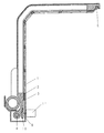
図1は、本発明の実施の形態1における空気調和機のエアーフィルターの取り付け部の構成を示す斜視図、図2は、同空気調和機の吸引ノズルの断面図(図1のA−A断面)である。
(Embodiment 1)
1 is a perspective view showing a configuration of an air filter mounting portion of an air conditioner according to
図1、図2において、2は、熱交換器(図示せず)の上流側に配され熱交換器に流入する空気の塵埃を除去するエアーフィルターで、フィルターワク1に支持固定され、そのエアーフィルター2の上流側の表面に沿って左右に駆動可能な吸引ノズル3が設けられる。
1 and 2, 2, the heat exchanger in an air filter for removing dust from air is disposed in the upstream side flows into the heat exchanger (not shown), fixedly supported on the
吸引ノズル3は、フィルターワク1の下端に設置したシャフト4と、上端に設置したガ
イドレール5により、エアーフィルター2の表面と極めて狭い隙間を保って支持されて摺動可能としている。また、吸引ノズル3にはワイヤー10が連結されており、このワイヤー10はフィルターワク1の左右端に設けたローラー9で支持されて、どちらか一方のローラー9には駆動モータ11が連結されている。吸引ノズル3の裏面には、図3に示すようにエアーフィルター2の表面に対向して開口するスリット状の吸引孔12が設けられている。
The
6は、吸引ダクトで一端が吸引ノズル3に、他端は吸引装置7に連結される。吸引ダクト6は吸引ノズル3の移動に差し支えないように折り曲げ可能な可撓性の富んだ蛇腹ホースなどで形成されている。吸引装置7には電動送風機(図示せず)が内蔵され、前記電動送風機の排気は後部に接続された排気ダクト8を通して室外に排気される。
A
このように構成された空気調和機の動作、作用について説明する。なお、本空気調和機の冷・暖房運転は、従来のものと同一なので、その説明は省略する。 The operation and action of the air conditioner thus configured will be described. In addition, since the cooling / heating operation of this air conditioner is the same as the conventional one, its description is omitted.
空気調和機本体の運転停止後に、吸引装置7の運転を開始すると、吸引ダクト6が連結された吸引ノズル3の裏面に設けた吸引孔12から空気が吸い込まれる。そして、エアーフィルター2の右端に位置していた吸引ノズル3は、駆動モータ11を運転することにより、それに連結されたワイヤー10によって、エアーフィルター2に沿って左端まで移動する。この時、エアーフィルター2の表面に付着した塵埃は吸引ノズル3に設けた吸引孔12から吸込まれ、塵埃は吸引ダクト6、吸引装置7、排気ダクト8を経由して室外へ排出されるため、エアーフィルター全面に付着した塵埃を吸引清掃することができものである。また、駆動モータ11を逆回転させると吸引ノズル3は右方向へ移動して元の位置(エアーフィルター2の右端)へ戻すことができる。
When the operation of the
そして、前述のような吸引清掃を良好に行うためには、エアーフィルター2と吸引ノズル3の隙間を一定に保つことが重要となるが、この実施の形態では、吸引ノズル3はフィルターワク1の下端に設けたシャフト4とフィルターワク1の上端に設けたガイドレール5でしっかりと支持され摺動可能としたため、エアーフィルター2との隙間を一定に保ちながら安定した動作を得ることができ、良好な吸引清掃を行うことが可能となる。
In order to perform the above-described suction cleaning satisfactorily, it is important to keep the gap between the
尚、このフィルター2の自動吸引清掃動作は、空気調和機の運転中に行なってもかまわない。
The automatic suction cleaning operation of the
(実施の形態2)
図4は、本発明の実施の形態2における空気調和機のエアーフィルターの取り付け部の断面図である。なお上記実施の形態と同一部分については同一符号を付してその説明を省略する。
(Embodiment 2)
FIG. 4 is a cross-sectional view of the air filter attachment portion of the air conditioner according to
吸引ノズル3の上端部にピン13を固着し、そのピン13に滑車14を回転自在に設け、さらにこの滑車14の外周に凹形状の溝14aを形成したものである。一方、フィルターワク1には滑車14の溝14aに相対する位置にガイドレール5が配されており、このガイドレール5に滑車14が噛合わされて、吸引ノズル3を支持する構造となっている。
A
この実施の形態によれば、吸引ノズル3がエアーフィルター2に沿って移動するとき、吸引ノズル3の上端に設けた滑車14がフィルターワク1に設けたガイドレール5に沿って回転するため、ガイドレール5と吸引ノズル3間の摺動抵抗が低減され、吸引ノズル3はさらに円滑に移動することができる。
According to this embodiment, when the
尚、上記滑車14は、吸引ノズル3の可動方向に複数個設けてもかまわない。
A plurality of
また、図5に示すように、フィルターワク1に設けたシャフト4を中空構造にすれば、シャフト4の自重による撓みが軽減されるため、このシャフト4に支持されて移動する吸引ノズル3は、エアーフィルター2との隙間をより一層一定に保ちながら移動することができる。
Further, as shown in FIG. 5, if the
また、図6に示すように、吸引ノズル3のシャフト4が貫通している部分の近傍にリブ16を形成し、フィルターワク1のリブ16に対向する部位に第2のガイドレール5aを設け、リブ16を第2のガイドレール5aで支持すると共に摺動可能に噛合せるようにすれば、吸引ノズル3の自重を前記第2のガイドレール5aが受け持つことになるため、吸引ノズル3を支えているシャフト4の撓みが上記の例と同様軽減され、吸引ノズル3は、エアーフィルター2との隙間をより一定に保ちながら移動することができる。
Further, as shown in FIG. 6, a
尚、上記リブ16をフィルターワク1に、第2のガイドレール5aを吸引ノズル3側に設けても同様の効果を得ることができる。
The same effect can be obtained by providing the
(実施の形態3)
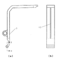
図7は、本発明の実施の形態3におけるフィルター装置の断面図である。なお上記実施の形態と同一部分については同一符号を付してその説明を省略する。
(Embodiment 3)
FIG. 7 is a cross-sectional view of the filter device according to
上記実施の形態では、吸引ノズル3を左右方向に移動させる手段として、駆動モータ11で回転駆動されるローラー9で移動するワイヤ10を用いたが、本実施の形態では、ベルト17を用いるものである。ベルト17はフィルターワク1の左右端に設けたローラー9に環状に張架され、その一部が吸引ノズル3に連結されている。
In the above embodiment, the
この実施の形態によれば、ベルト17とローラー9との掛り代(接触面積)をワイヤー10の場合に較べ大きく取ることができるため、駆動モータ11からの駆動力がスリップすることなく吸引ノズル3に伝達され、吸引ノズル3を安定して移動させることができる。
According to this embodiment, since the contact amount (contact area) between the
(実施の形態4)
図8は、本発明の実施の形態4における空気調和機のエアーフィルターの取り付け部の要部断面図である。
(Embodiment 4)
FIG. 8 is a cross-sectional view of a main part of an air filter attachment part of an air conditioner according to
なお上記実施の形態と同一部分については同一符号を付してその説明を省略する。 The same parts as those in the above embodiment are denoted by the same reference numerals and the description thereof is omitted.
上記実施の形態1、2、3では、吸引ノズル3を移動させる手段として、ローラー9を介在させたが、本実施の形態では、図8に示すように、外周におねじを形成したシャフト4の端部と駆動モーター11とを連結し、前記吸引ノズル3のシャフト4が貫通する部分に前記おねじにねじ嵌合するめねじを形成して、シャフト4と嵌合させて吸引ノズル3を支持したものである。
In the first, second and third embodiments, the
上記構成によれば、シャフト4と吸引ノズル3がねじ嵌合しているので、駆動モータ11でシャフト4を回転させることにより、吸引ノズル3をエアーフィルター2に沿って移動させる事ができる。本実施の形態によれば、上記実施の形態で述べたワイヤー10やベルト17、それらを保持するローラー9などを無くすことができるとともに、その部分でのロスが無いので、駆動モータ11からの伝達力をさらに向上させることがでる。
According to the above configuration, since the
また、図9に示すように、上記実施の形態4におけるシャフト4の中心部を金属材料で形成して、その表面に樹脂材料でおねじを成形するようにすれば、シャフト4の全体を金
属で形成するよりも軽量化が図られるので、シャフト4の自重による撓みも軽減でき、吸引ノズル3の良好な駆動動作を得ることが可能となる。しかもシャフト4の表面のおねじを樹脂成形で形成できるので、製造時間が短縮され、安価に形成することができる。
Further, as shown in FIG. 9, if the central portion of the
以上のように、本発明にかかる空気調和機は、エアーフィルターを外すことなく、エアーフィルターに付着した塵埃の吸引清掃を自動的に且つ良好に行うことができるので、各種空調機器、送風機器、空気清浄機等に広く適用できるものである。 As described above, the air conditioner according to the present invention, without removing the air filter, it is possible to perform suction cleaning of dust adhered to the air filter automatically and favorably, various air-conditioning equipment, blown equipment, It can be widely applied to air cleaners and the like.
1 フィルターワク
2 エアーフィルター
3 吸引ノズル
4 シャフト
5 ガイドレール
5a 第2のガイドレール
6 吸引ダクト
7 吸引装置
8 排気ダクト
9 ローラー
10 ワイヤー
11 駆動モータ
12 吸引孔
14 滑車
16 リブ
17 ベルト
1
Claims (5)
Priority Applications (1)
| Application Number | Priority Date | Filing Date | Title |
|---|---|---|---|
| JP2003386635A JP3918805B2 (en) | 2003-11-17 | 2003-11-17 | Air conditioner |
Applications Claiming Priority (1)
| Application Number | Priority Date | Filing Date | Title |
|---|---|---|---|
| JP2003386635A JP3918805B2 (en) | 2003-11-17 | 2003-11-17 | Air conditioner |
Publications (2)
| Publication Number | Publication Date |
|---|---|
| JP2005147546A JP2005147546A (en) | 2005-06-09 |
| JP3918805B2 true JP3918805B2 (en) | 2007-05-23 |
Family
ID=34694268
Family Applications (1)
| Application Number | Title | Priority Date | Filing Date |
|---|---|---|---|
| JP2003386635A Expired - Fee Related JP3918805B2 (en) | 2003-11-17 | 2003-11-17 | Air conditioner |
Country Status (1)
| Country | Link |
|---|---|
| JP (1) | JP3918805B2 (en) |
Families Citing this family (9)
| Publication number | Priority date | Publication date | Assignee | Title |
|---|---|---|---|---|
| JP4484875B2 (en) * | 2004-10-26 | 2010-06-16 | パナソニック株式会社 | Air conditioner with indoor unit with automatic air filter cleaning function |
| CN101243291B (en) * | 2005-08-12 | 2010-09-08 | 东芝开利株式会社 | Indoor unit of air-conditioner |
| JP2007101103A (en) * | 2005-10-06 | 2007-04-19 | Matsushita Electric Ind Co Ltd | Air conditioner |
| JP4701978B2 (en) * | 2005-10-06 | 2011-06-15 | パナソニック株式会社 | Air conditioner filter device |
| JP2007107803A (en) * | 2005-10-13 | 2007-04-26 | Matsushita Electric Ind Co Ltd | Air conditioner |
| JP2007107808A (en) * | 2005-10-13 | 2007-04-26 | Matsushita Electric Ind Co Ltd | Air conditioner |
| JP2007107804A (en) * | 2005-10-13 | 2007-04-26 | Matsushita Electric Ind Co Ltd | Air conditioner |
| JP2009180465A (en) * | 2008-01-31 | 2009-08-13 | Kowa Co Ltd | Air conditioner |
| WO2016143010A1 (en) * | 2015-03-06 | 2016-09-15 | 三菱電機株式会社 | Air conditioner |
-
2003
- 2003-11-17 JP JP2003386635A patent/JP3918805B2/en not_active Expired - Fee Related
Also Published As
| Publication number | Publication date |
|---|---|
| JP2005147546A (en) | 2005-06-09 |
Similar Documents
| Publication | Publication Date | Title |
|---|---|---|
| KR20070072829A (en) | Air conditioning apparatus provided with indoor unit having air filter automatic cleaning function | |
| JP3918805B2 (en) | Air conditioner | |
| JP4050774B2 (en) | Air conditioner | |
| JPWO2004081461A1 (en) | Air conditioner with indoor unit with automatic air filter cleaning function | |
| JP2007330652A (en) | Rotating rotor, floor suction tool for vacuum cleaner, vacuum cleaner, and air-conditioner | |
| JP3807451B2 (en) | Air conditioner | |
| TWI344531B (en) | Air conditioner with indoor unit having automatic filter cleaning function | |
| JP2005024134A (en) | Air conditioner | |
| JP4645059B2 (en) | Filter device and air conditioner | |
| JP4665604B2 (en) | Air conditioner | |
| JP2008061785A (en) | Rotor, floor suction tool for vacuum cleaner, vacuum cleaner and air conditioner | |
| JP2006289235A (en) | Air cleaner | |
| JP3918802B2 (en) | Air conditioner | |
| JP5284762B2 (en) | Filter cleaning device and air conditioning device | |
| JP4946452B2 (en) | Air conditioner filter device | |
| KR100625593B1 (en) | Filter equipment | |
| JP3807452B2 (en) | Air conditioner | |
| JP2007127337A (en) | Air conditioner | |
| JP2008032249A (en) | Cleaning device for filter | |
| JP2006105591A (en) | Filter device for air-conditioner | |
| JP4599970B2 (en) | Air conditioner | |
| JP4599982B2 (en) | Air conditioner filter device | |
| JP5061837B2 (en) | Air conditioner | |
| JP2009092272A (en) | Cleaning mechanism of air conditioner | |
| JP4507758B2 (en) | Air conditioner filter device |
Legal Events
| Date | Code | Title | Description |
|---|---|---|---|
| A621 | Written request for application examination |
Free format text: JAPANESE INTERMEDIATE CODE: A621 Effective date: 20060719 |
|
| A871 | Explanation of circumstances concerning accelerated examination |
Free format text: JAPANESE INTERMEDIATE CODE: A871 Effective date: 20060727 |
|
| A975 | Report on accelerated examination |
Free format text: JAPANESE INTERMEDIATE CODE: A971005 Effective date: 20060803 |
|
| A131 | Notification of reasons for refusal |
Free format text: JAPANESE INTERMEDIATE CODE: A131 Effective date: 20060808 |
|
| RD01 | Notification of change of attorney |
Free format text: JAPANESE INTERMEDIATE CODE: A7421 Effective date: 20060821 |
|
| A521 | Request for written amendment filed |
Free format text: JAPANESE INTERMEDIATE CODE: A523 Effective date: 20061004 |
|
| TRDD | Decision of grant or rejection written | ||
| A01 | Written decision to grant a patent or to grant a registration (utility model) |
Free format text: JAPANESE INTERMEDIATE CODE: A01 Effective date: 20070123 |
|
| A61 | First payment of annual fees (during grant procedure) |
Free format text: JAPANESE INTERMEDIATE CODE: A61 Effective date: 20070205 |
|
| FPAY | Renewal fee payment (event date is renewal date of database) |
Free format text: PAYMENT UNTIL: 20100223 Year of fee payment: 3 |
|
| FPAY | Renewal fee payment (event date is renewal date of database) |
Free format text: PAYMENT UNTIL: 20110223 Year of fee payment: 4 |
|
| FPAY | Renewal fee payment (event date is renewal date of database) |
Free format text: PAYMENT UNTIL: 20120223 Year of fee payment: 5 |
|
| FPAY | Renewal fee payment (event date is renewal date of database) |
Free format text: PAYMENT UNTIL: 20130223 Year of fee payment: 6 |
|
| FPAY | Renewal fee payment (event date is renewal date of database) |
Free format text: PAYMENT UNTIL: 20140223 Year of fee payment: 7 |
|
| LAPS | Cancellation because of no payment of annual fees |