JP3916438B2 - Latent heat recovery type water heater - Google Patents
Latent heat recovery type water heater Download PDFInfo
- Publication number
- JP3916438B2 JP3916438B2 JP2001332082A JP2001332082A JP3916438B2 JP 3916438 B2 JP3916438 B2 JP 3916438B2 JP 2001332082 A JP2001332082 A JP 2001332082A JP 2001332082 A JP2001332082 A JP 2001332082A JP 3916438 B2 JP3916438 B2 JP 3916438B2
- Authority
- JP
- Japan
- Prior art keywords
- water
- drain
- pipe
- heating system
- latent heat
- Prior art date
- Legal status (The legal status is an assumption and is not a legal conclusion. Google has not performed a legal analysis and makes no representation as to the accuracy of the status listed.)
- Expired - Fee Related
Links
Images


Description
【0001】
【発明の属する技術分野】
本発明は、燃焼排ガスの潜熱エネルギを回収して水を加熱する潜熱回収型給湯器に関する。特には、水蒸気が復水して生じたドレインの排出系統に改良を加え、配管工事の手間がかからないようにした潜熱回収型給湯器に関する。
【0002】
【従来の技術】
潜熱回収型給湯器は、近年では熱効率が90%以上のものも開発されつつあり、省エネ機器として注目されている。
図3は、従来の代表的な潜熱回収型給湯器の本体の構成と主たる配管の系統を模式的に示す図である。
この給湯器本体50は、台所や洗面所へ温水を供給する主給湯系統51と、浴室暖房乾燥機や室内放熱器等の暖房機器103に温水を供給する暖房系統53と、風呂137の追い焚きを行う風呂追い焚き系統55と、を有する。
【0003】
主給湯系統51の燃焼室57内には、一次熱交換器59、二次(潜熱回収)熱交換器61、バーナ63、燃焼ファン(図示されず)等が備えられている。暖房系統53の燃焼室65内にも、一次熱交換器67、二次(潜熱回収)熱交換器69、バーナ71等が備えられている。追い焚き系統55は、暖房系統53から給熱を受ける水−水熱交換器73を有する。
【0004】
各バーナ63、71には、ガス供給源からガス供給管(図示されず)を通って燃焼用ガスが供給される。ガス供給管から各バーナへの分岐部には元ガス電磁弁(図示されず)が備えられている。各バーナへ分岐したガス供給管には、各々ガス比例弁とガス電磁弁(いずれも図示されず)が備えられている。各給湯系統のバーナへ供給されるガスの量はガス比例弁で制御され、各バーナへの供給のオンオフはガス電磁弁で操作される。
各バーナには点火プラグ、フレームロッド(いずれも図示されず)が備えられている。各点火プラグはイグナイター(図示されず)で点火されて、各バーナに供給された燃焼用ガスを燃焼させる。フレームロッドは火炎の有無を検知して、不完全燃焼を防ぐ。
【0005】
主給湯系統51は、水源から水が供給される給水配管75と、台所や洗面所に温水を供給する給湯配管77を有する。給水配管75は、燃焼室57内の二次熱交換器61を通過し、燃焼室57を出て、再度燃焼室内の一次熱交換器59を通過し、給湯配管77に繋がっている。燃焼室55内では、順に、バーナ63、一次熱交換器59、二次熱交換器61が、燃焼ガスの流れ方向に沿って並ぶように配置されている。
【0006】
燃焼室55内の二次熱交換器61の下方には、受け皿79が取り付けられている。この受け皿79はドレイン配管81を介してドレイン受け83に連通している。ドレイン受け83の底面には水抜き栓85が設けられ、上部には排水管87が設けられている。
【0007】
次に、一次熱交換器59と二次熱交換器61による潜熱回収作用について説明する。
給水配管75から供給された水は、最初に二次熱交換器61を通過する。そして、次に一次熱交換器59を通過する。ここで、一次熱交換器59の下方のバーナ63に燃焼用ガスが供給されており、点火プラグで点火される。そして燃焼ファンから燃焼用空気が送られて燃焼し、火炎と燃焼ガスを発生する。この火炎による輻射熱と燃焼ガスによって一次熱交換器59が加熱され、管内を流れる水が加熱される。そして、燃焼ガスはファンによって上方、すなわち、二次熱交換器61方向へ送られる。燃焼ガス中に含まれる水蒸気が二次熱交換器61に接し、二次熱交換器61の配管を流れる水が水蒸気の潜熱を吸収する。これにより、水蒸気は凝縮し、水に変化する。
【0008】
水蒸気から変化した水は、受け皿79に滴下し、ドレイン配管81を通ってドレイン受け83に溜まる。ドレイン受け83が所定の水位に達すると排水管87から排水される。また、燃焼ガスは、二次熱交換器61の側方に設けられた排気口89から排気される。
【0009】
一方、二次熱交換器61内を通過している水は、燃焼ガスの凝縮熱を吸収して温度が上昇する。そして、温度が上昇した水が一次熱交換器59へ送られるため、最終的に供給される温水は効率的に加熱される。
【0010】
給水配管75と給湯配管77はバイパス電磁弁91が付設されたバイパス管93で接続している。給水配管75、二次熱交換器出側の給湯配管77a、バイパス管下流の給湯配管77bには各々サーミスタ95が備えられている。これらのサーミスタ95は各配管内の水の温度を検知する。これらの温度から給湯配管77から供給される温水の温度が適宜な温度となるように、バイパス管93のバイパス電磁弁91を調整して、温水と水の混合量を変化させる。
【0011】
また、二次熱交換器61出側の給水配管75には水量センサ97が備えられており、配管内の水の量を調整している。さらに、給湯配管77aには給湯ハイリミットスイッチ99が備えられている。ハイリミットスイッチ99は、燃焼室57の温度が異常に高くなった場合に作動し、給湯器50の電気回路を遮断する。給湯配管77bにはまた水制御弁101が備えられ、給湯配管77から供給される温水の圧力を制御する。
【0012】
次に、暖房系統53について説明する。
暖房系統53の燃焼室65内には、一次熱交換器67、二次熱交換器69、バーナ71等が備えられている。暖房系統53は、燃焼室65から暖房装置103へ往く往き配管105と、暖房装置103から燃焼室65へ戻る戻り配管107とを有する。各暖房装置103への往き配管105及び戻り配管107はヘッダ109から分岐している。往き配管105と戻り配管107は、暖房装置103と燃焼室65間の循環管路を構成しており、循環管路内に設けられたポンプ111により管路内の水が循環する。
【0013】
戻り配管107は、燃焼室65内の二次熱交換器69を通過し、燃焼室65を出て、一次シスターン113に貯留される。そしてシスターン113から出て、ポンプ111の下流で高温往き配管105Hと低温往き配管105Lに分岐している。高温往き配管105Hはその後再度燃焼室65内の一次熱交換器67を通過して暖房装置に接続し、低温往き配管105Lはそのまま暖房装置に接続する。
【0014】
シスターン113にはこの例では3本の電極からなる水位センサ115が備えられている。また、シスターン113には主給湯系統51の給水配管75から分岐した水補給水管117と、末端が外部に開いた排水管119が接続している。水補給水管117には補給水電磁弁118が設けられている。そして、水位センサ115で検知されたシスターン113の水位が高水位に達すると、排水管119から排水される。また、低水位まで下がると、補給水電磁弁118が開かれて給水配管75から水補給水管117を通って水が補給される。このように、シスターン113内の水位は所定範囲内に維持される。
【0015】
燃焼室65内では、順に、バーナ71、一次熱交換器67、二次熱交換器69が、燃焼ガスの流れ方向に並ぶように配置されている。燃焼室65内の二次熱交換器69の下方には、受け皿121が取り付けられている。この受け皿121はドレイン配管123を介してドレイン受け83に連通している。
【0016】
一次熱交換器57と二次熱交換器59による潜熱回収作用は、給湯系統の潜熱回収作用と同様である。
【0017】
高温往き配管105Hと低温往き配管105Lは、低温逆止弁125を備えたバイパス管127で接続している。二次熱交換器出側の配管107a、一次熱交換器出側の高温往き配管105H、バイパス管下流の低温往き配管105Lにはサーミスタ129が備えられている。これらのサーミスタ129は各配管内の水の温度を検知する。これらの温度から往き配管105から供給される温水の温度が適宜な温度となるように、バーナ71の燃焼度合い等を制御する。
【0018】
さらに、一次熱交換器出側の高温往き配管105Hには給湯ハイリミットスイッチ131が備えられている。ハイリミットスイッチ131は、燃焼室65内の温度が以上に高くなった場合に作動し、給湯器50の電気回路を遮断する。
【0019】
また、戻り配管107と高温往き配管105H間には、熱動弁133を備えたバイパス管135が接続している。このバイパス管135は、凍結防止運転時に、燃焼部を作動させずに水を循環させるためのものである。このバイパス管135は、風呂追い焚き系統55と水−水熱交換器73を形成している。
【0020】
次に、風呂追い焚き系統55について説明する。
風呂追い焚き系統55は、給湯器50から風呂137への往き配管139と風呂137からの戻り配管141を有する。往き配管139と戻り配管141は、風呂137と給湯器50間の循環管路を構成しており、循環管路内に設けられたポンプ143により水が循環する。
【0021】
循環管路には主給湯系統51の給湯配管77から分岐した注湯管145と、給水配管75から分岐した注水管147が合流した給湯管151が、往き戻り切替弁153を介して接続している。注湯配管145には逆止弁155、注湯電磁弁157が備えられている。注水管147にはバキュームブレーカ156と注水電磁弁161が備えられている。バキュームブレーカ156と逆止弁155は、断水等で給水圧が負圧になった場合に作動して、循環管路の水が逆流することを防ぐ。注水電磁弁161、注湯電磁弁157は風呂給湯系統55への水又は温水の供給をオンオフする。
【0022】
給湯管151には注湯量センサ163と逆止弁165が備えられている。注湯量センサ163は、給湯管151から風呂137へ供給される温水の量を検知する。逆止弁155は、循環管路の水の逆流を防ぐ。
【0023】
給湯管151と循環管路の合流点の上流には水位センサ167と、水流スイッチ169を備えたポンプ143が備えられている。水位センサ167は、風呂戻り配管141から循環管路へ供給される温水の量を検知する。ポンプ143には過圧防止安全装置171が備えられ、循環水の温度変化に伴う循環管路内の水圧を制御している。水流スイッチ169は循環管路内の循環水の流れ方向を検知して循環水の逆流を防ぐ。
戻り配管141には、サーミスタ173が備えられている。
【0024】
往き配管139の一部は、上述のように暖房系統53と水−水熱交換器73を形成している。この水−水熱交換器73で循環管路内の水が、暖房系統の温水と熱交換する。
【0025】
給湯器50の本体内には複数の温度ヒューズ177が備えられており、機器内部の温度が以上に高くなった場合に作動して給湯器50の電気回路を遮断する。また、上述のサーミスタで検知されて温度信号は本体内に設けられた電装基板179に入力されて、各弁、ファン等の制御が行われる。電装基板179は浴室リモコンや台所リモコンに接続しており、各部の操作や温度設定をリモコン操作で行うことができる。
【0026】
【発明が解決しようとする課題】
従来の潜熱回収型給湯器は、上述のように、水蒸気の凝縮によって発生した凝縮水(ドレイン)を排水するための排水管87、119が設けられている。そしてこれらの排水管を排水場所まで引く必要がある。ところが、例えば近年の集合住宅のように、片側が廊下に面するパイプシャフト内に給湯器を設置するような場合には、給湯器の近傍に排水設備が存在しないため、ドレイン排出用の配管工事を行うのは非常に手間がかかる。
【0027】
本発明は上記の問題点に鑑みてなされたものであって、ドレイン排水の配管工事が不要な潜熱回収型給湯器を提供することを目的とする。
【0028】
【課題を解決するための手段】
本発明の潜熱回収型給湯器は、 給湯器本体と、該本体から暖房装置に温水を供給する循環管路を有する暖房系統と、を備え、 前記給湯器本体が、 ガスバーナと、 該バーナの燃焼排ガス中の水蒸気の潜熱によって水を加熱する潜熱回収熱交換器と、 該熱交換器で生じる凝縮水を含むドレインを受けるドレイン受けと、 該ドレイン受けに溜まったドレインを前記暖房系統の循環管路に送るドレイン送出系統と、を備え、 前記ドレイン受けが、前記暖房系統のシスターンであり、 前記暖房系統に、開閉機構を備えた端末が設けられており、 前記シスターンに水位センサが付設され、該水位センサで検知された水位が所定の水位に達すると前記開閉機構を開いて前記端末から前記暖房系統内の排水を行うことを特徴とする。
ドレインを暖房系統の循環管路に送出するため、給湯器本体から排水場所までドレインを送る排水設備が不要になる。
【0029】
本発明においては、 前記ドレイン受けを、前記暖房系統のシスターンと兼用させれば、新たにドレイン受けを設ける必要がない。
【0030】
本発明においては、 前記シスターンに中和剤が封入されている、もしくは、中和剤注入手段が付設されている、もしくは、 前記シスターンに水道水注入手段が付設されていることが好ましい。
ドレイン排水を中和してPHを低下させることができる。または、 前記ドレイン受けに水道水補給手段を付設すれば、ドレインを水道水で中和させることができる。ここで、水道水注入手段は、シスターンの水補給手段と兼用できる。
【0031】
本発明においては、 前記暖房系統に、開閉機構を備えた端末が設けられており、 前記シスターンに水位センサが付設され、該水位センサで検知された水位が所定の水位に達すると前記開閉機構を開いて前記端末から前記暖房系統水の排水を行うことが好ましい。
ドレインの注入によりシスターンの水位が上昇した場合、暖房系統中の端末から暖房系統をパージすることでシスターンの水位を一定に保つことができる。なお、端末は台所のシンクや洗濯機の防水パン等の排水設備の既に備わっている部分とすれば、ドレイン排水のための新たな設備は不要である。
【0032】
本発明においては、 さらに、前記暖房系統と風呂循環水との水−水熱交換器を備えることとすれば、風呂の追い焚きも行うことができる。
【0033】
以下、図面を参照しつつ説明する。
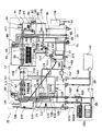
図1は、本発明の第1の実施の形態に係る潜熱回収型給湯器の本体の構成と主たる配管の系統を模式的に説明する図である。
この給湯器10は、ドレイン受けの構造やドレイン受け近傍の配管、またシスターン近傍の配管と暖房装置往き配管が、図3の給湯器と異なるのみで、他の部分は図3の給湯器と同じ構造・作用である。そこで、以下では異なる部分を中心に説明する。
【0034】
この給湯器10においては、ドレイン受け83及びシスターン113に従来の排水管が設けられていない。そして、ドレイン受け83から延びた排水管11が暖房系統のシスターン113の出側の戻り管路107bに接続している。この排水管11には、排水電磁弁13が備えられている。
【0035】
また、暖房系統53において、戻り管路107のヘッダ109の上流で端末排水管15が分岐している。端末排水管15には電磁弁17が設けられており、末端は開放されている。ここで、末端は排水が容易な台所のシンクや洗濯機の防水パン等につながっている。このような場所には、近傍の暖房系統から簡単に排水管を引くことができる。
【0036】
ドレイン受け83には、水位センサ(図示されず)が設けられており、ドレイン受け83内のドレイン水の水位を検知する。ドレイン受け83には、中和剤として炭酸カルシウム(固体)を封入しておいてもよい。
【0037】
ドレイン受け83内のドレイン水の水位が所定の水位に達すると、排水管11の排水電磁弁13を開き、ドレインを暖房系統の戻り管路107に排水する。戻り管路107に入ったドレイン水はシスターン113に送られ、暖房系統内を循環する。ここで、ドレイン水は、暖房系統内を循環している水で薄められるため、配管等の腐食を防ぐことができる。また、シスターン113には水補給水管117が接続しており、シスターン113内のドレインは適宜な量の水道水と混合されて、アルカリ性を緩和できる。また、シスターン113に中和剤として炭酸カルシウムが封入されていてもよい。
【0038】
ドレイン水の合流により暖房系統内の水量が増えて、シスターン113の水位が高水位に達すると、暖房戻り管路107から分岐した端末排水管15に設けられた電磁弁17を開いて、水位が所定値に下がるまで、端末排水管15から暖房系統内の水をシンクや防水パン等に排水する。
【0039】
このような構成により、ドレイン水やシスターンのオーバーフローを、給湯器から排水場所まで延びる長い排水管を設けずに排水することができる。
【0040】
図2は、本発明の第2の実施の形態に係る潜熱回収型給湯器の本体の構成と主たる配管の系統を模式的に示す図である。
この給湯器30は、ドレイン受けの構造やドレイン受け近傍の配管、またシスターン近傍の配と暖房装置往き配管が、図1の給湯器と異なるのみで、他の部分は図1の給湯器と同じ構造・作用である。
【0041】
この給湯器30は、ドレイン受けが設けられておらず、また、シスターン113に排水管が設けられていない。そして、ドレイン受け皿79、121から延びたドレイン管81、123が直接シスターン113に接続している。また、暖房系統53において、戻り管路107のヘッダ109の上流から端末排水管15が分岐している。端末排水管15には電磁弁17が設けられており、末端は開放されている。ここで、末端は排水が容易な台所のシンクや洗濯機の防水パン等につながっている。このような場所には、近傍の暖房系統から簡単に排水管を引くことができる。
【0042】
このような構成により、受け皿79、121に溜まったドレインはシスターン113に貯留される。シスターン113の水位が高水位に達すると、暖房戻り管路107から分岐した端末排水管15に設けられた電磁弁17を開いて、水位が所定値に下がるまで、端末排水管15から暖房系統内の水をシンクや防水パン等に排水する。
【0043】
【発明の効果】
以上の発明から明らかなように、本発明によれば、ドレイン受けに溜まったドレインを暖房系統へ送出するため、ドレイン排水用の配管工事が不要な潜熱回収型給湯器を提供することができる。また、ドレイン受けをシスターンと兼用すれば部品を共通化することができ、コンパクト化及びコストダウンできる。
【図面の簡単な説明】
【図1】本発明の第1の実施の形態に係る潜熱回収型給湯器の本体の構成と主たる配管の系統を模式的に示す図である。
【図2】本発明の第2の実施の形態に係る潜熱回収型給湯器の本体の構成と主たる配管の系統を模式的に示す図である。
【図3】従来の代表的な潜熱回収型給湯器の本体の構成と主たる配管の系統を模式的に示す図である。
【符号の説明】
10、30 給湯器 11 排水管
13 排水電磁弁 15 端末排水管
17 電磁弁 79、121 受け皿
81、123 ドレイン管[0001]
BACKGROUND OF THE INVENTION
The present invention relates to a latent heat recovery type water heater that recovers latent heat energy of combustion exhaust gas and heats water. In particular, the present invention relates to a latent heat recovery type hot water heater in which a drain discharge system generated by condensing water vapor is improved so that piping work is not required.
[0002]
[Prior art]
In recent years, a latent heat recovery type water heater has been developed with a thermal efficiency of 90% or more, and is attracting attention as an energy-saving device.
FIG. 3 is a diagram schematically showing a configuration of a main body of a typical typical latent heat recovery type water heater and a main piping system.
The water heater
[0003]
In the
[0004]
Each
Each burner is provided with a spark plug and a frame rod (both not shown). Each spark plug is ignited by an igniter (not shown) to burn the combustion gas supplied to each burner. The flame rod detects the presence of a flame and prevents incomplete combustion.
[0005]
The main hot
[0006]
A
[0007]
Next, the latent heat recovery action by the
The water supplied from the
[0008]
The water changed from the water vapor is dropped on the
[0009]
On the other hand, the water passing through the
[0010]
The
[0011]
In addition, the
[0012]
Next, the
In the
[0013]
The
[0014]
In this example, the
[0015]
In the
[0016]
The latent heat recovery action by the
[0017]
The high temperature
[0018]
Furthermore, a hot water supply
[0019]
Further, a
[0020]
Next, the
The
[0021]
A hot-
[0022]
The hot
[0023]
A
The
[0024]
Part of the
[0025]
A plurality of temperature fuses 177 are provided in the main body of the
[0026]
[Problems to be solved by the invention]
As described above, the conventional latent heat recovery type water heater is provided with
[0027]
This invention is made | formed in view of said problem, Comprising: It aims at providing the latent-heat-recovery type hot water heater which does not need piping construction of drain drainage.
[0028]
[Means for Solving the Problems]
The latent heat recovery type water heater of the present invention includes a water heater body and a heating system having a circulation line for supplying hot water from the body to the heating device, the water heater body includes a gas burner, and combustion of the burner A latent heat recovery heat exchanger that heats water by the latent heat of water vapor in the exhaust gas, a drain receiver that receives a drain containing condensed water generated in the heat exchanger, and a drain that accumulates in the drain receiver is connected to a circulation line of the heating system the drain and delivery lines, Bei give a send, the drain receiving is a cistern of the heating system, the heating system, and terminal provided with an opening and closing mechanism is provided, the water level sensor is attached to the cistern, When the water level detected by the water level sensor reaches a predetermined water level, the opening / closing mechanism is opened to drain the heating system from the terminal .
Since the drain is sent to the circulation line of the heating system , a drainage facility for sending the drain from the water heater body to the drainage place becomes unnecessary.
[0029]
In the present invention, if the drain receiver is also used as a cistern of the heating system, it is not necessary to newly provide a drain receiver.
[0030]
In the present invention, it is preferable that a neutralizing agent is enclosed in the cistern, or a neutralizing agent injecting unit is attached, or a tap water injecting unit is attached to the cistern.
The drainage can be neutralized to reduce PH. Alternatively, if a tap water supply means is attached to the drain receptacle, the drain can be neutralized with tap water. Here, the tap water injection means can also be used as a water supply means for cistern.
[0031]
In the present invention, the heating system is provided with a terminal having an opening / closing mechanism, a water level sensor is attached to the systern, and the opening / closing mechanism is opened when a water level detected by the water level sensor reaches a predetermined water level. it is preferred to carry out the drainage of the heating system water from the previous SL end end open.
When the water level of the cistern rises due to the drain injection, the water level of the cistern can be kept constant by purging the heating system from the terminal in the heating system. If the terminal is already equipped with a drainage facility such as a kitchen sink or a waterproof pan for a washing machine, a new facility for drainage drainage is unnecessary.
[0032]
In the present invention, if a water-water heat exchanger of the heating system and bath circulating water is further provided, the bath can be reheated.
[0033]
Hereinafter, it demonstrates, referring drawings.
FIG. 1 is a diagram schematically illustrating the configuration of the main body of the latent heat recovery type hot water heater and the main piping system according to the first embodiment of the present invention.
The
[0034]
In the
[0035]
In the
[0036]
The
[0037]
When the drain water level in the
[0038]
When the amount of water in the heating system increases due to the confluence of the drain water and the water level of the
[0039]
With such a configuration, the drain water or the overflow of the cistern can be drained without providing a long drain pipe extending from the water heater to the drainage place.
[0040]
FIG. 2 is a diagram schematically showing a configuration of a main body and a main piping system of a latent heat recovery type hot water heater according to a second embodiment of the present invention.
This
[0041]
The
[0042]
With such a configuration, the drain accumulated in the
[0043]
【The invention's effect】
As apparent from the above invention, according to the present invention, since the drain accumulated in the drain receiver is sent to the heating system, it is possible to provide a latent heat recovery type water heater that does not require piping work for drain drainage. Further, if the drain receiver is also used as a cistern, the parts can be shared, and the size and cost can be reduced.
[Brief description of the drawings]
FIG. 1 is a diagram schematically showing a configuration of a main body and a main piping system of a latent heat recovery type hot water heater according to a first embodiment of the present invention.
FIG. 2 is a diagram schematically showing a configuration of a main body and a main piping system of a latent heat recovery type hot water heater according to a second embodiment of the present invention.
FIG. 3 is a diagram schematically showing a configuration of a main body and a main piping system of a conventional representative latent heat recovery type water heater.
[Explanation of symbols]
10, 30
Claims (3)
前記給湯器本体が、
ガスバーナと、
該バーナの燃焼排ガス中の水蒸気の潜熱によって水を加熱する潜熱回収熱交換器と、
該熱交換器で生じる凝縮水を含むドレインを受けるドレイン受けと、
該ドレイン受けに溜まったドレインを前記暖房系統の循環管路に送るドレイン送出系統と、
を備え、
前記ドレイン受けが、前記暖房系統のシスターンであり、
前記暖房系統に、開閉機構を備えた端末が設けられており、
前記シスターンに水位センサが付設され、該水位センサで検知された水位が所定の水位に達すると前記開閉機構を開いて前記端末から前記暖房系統内の排水を行うことを特徴とする潜熱回収型給湯器。A water heater body, and a heating system having a circulation line for supplying hot water from the body to the heating device,
The water heater body is
With a gas burner,
A latent heat recovery heat exchanger that heats water by the latent heat of water vapor in the combustion exhaust gas of the burner;
A drain receiver for receiving a drain containing condensed water generated in the heat exchanger;
A drain delivery system for sending the drain accumulated in the drain receptacle to the circulation line of the heating system;
Bei to give a,
The drain receiver is a systern of the heating system;
The heating system is provided with a terminal having an opening / closing mechanism,
A latent heat recovery type hot water supply, wherein a water level sensor is attached to the systern, and when the water level detected by the water level sensor reaches a predetermined water level, the opening / closing mechanism is opened to drain the heating system from the terminal. vessel.
Priority Applications (1)
| Application Number | Priority Date | Filing Date | Title |
|---|---|---|---|
| JP2001332082A JP3916438B2 (en) | 2001-10-30 | 2001-10-30 | Latent heat recovery type water heater |
Applications Claiming Priority (1)
| Application Number | Priority Date | Filing Date | Title |
|---|---|---|---|
| JP2001332082A JP3916438B2 (en) | 2001-10-30 | 2001-10-30 | Latent heat recovery type water heater |
Publications (3)
| Publication Number | Publication Date |
|---|---|
| JP2003130464A JP2003130464A (en) | 2003-05-08 |
| JP2003130464A5 JP2003130464A5 (en) | 2005-06-09 |
| JP3916438B2 true JP3916438B2 (en) | 2007-05-16 |
Family
ID=19147553
Family Applications (1)
| Application Number | Title | Priority Date | Filing Date |
|---|---|---|---|
| JP2001332082A Expired - Fee Related JP3916438B2 (en) | 2001-10-30 | 2001-10-30 | Latent heat recovery type water heater |
Country Status (1)
| Country | Link |
|---|---|
| JP (1) | JP3916438B2 (en) |
Families Citing this family (3)
| Publication number | Priority date | Publication date | Assignee | Title |
|---|---|---|---|---|
| JP3931162B2 (en) * | 2003-08-08 | 2007-06-13 | リンナイ株式会社 | Hot water heater |
| JP2006090564A (en) * | 2004-09-21 | 2006-04-06 | Tokyo Gas Co Ltd | Latent heat recovery type hot water heating device |
| JP4546850B2 (en) * | 2005-02-18 | 2010-09-22 | 高木産業株式会社 | Drain discharge method of heat source device and heat source device |
-
2001
- 2001-10-30 JP JP2001332082A patent/JP3916438B2/en not_active Expired - Fee Related
Also Published As
| Publication number | Publication date |
|---|---|
| JP2003130464A (en) | 2003-05-08 |
Similar Documents
| Publication | Publication Date | Title |
|---|---|---|
| JP3801885B2 (en) | Latent heat recovery type water heater | |
| JP2005337710A (en) | Draining device for water heater and unit bath wall penetration joint | |
| US4699091A (en) | Method and apparatus for utilizing waste heat in hot water heaters | |
| JP2002267254A (en) | Hot-water supply apparatus | |
| JP3916438B2 (en) | Latent heat recovery type water heater | |
| JP6297886B2 (en) | Water heater | |
| JP2011047566A (en) | Water heater | |
| JP3759444B2 (en) | Drain discharge device for water heater | |
| JP2006275309A (en) | Hot-water supply heating device | |
| JP2006090564A (en) | Latent heat recovery type hot water heating device | |
| JP5606140B2 (en) | Heat source device, heating device, freeze prevention control method thereof, and freeze prevention control program | |
| JP3907032B2 (en) | Water heater | |
| RU2715877C1 (en) | Method of heating boiler operation in heating system | |
| JP2017122533A (en) | Bath water heater | |
| JP4407783B2 (en) | Exhaust gas drain treatment equipment for latent heat recovery type heat source machine | |
| JP6863724B2 (en) | Hot water supply system | |
| JP5061153B2 (en) | Hot water storage hot water supply system and cogeneration system | |
| EP0635683B1 (en) | High-efficiency combined boiler | |
| JP2002048413A (en) | Water heater | |
| JP4602062B2 (en) | Water heater | |
| JP4624091B2 (en) | Water heater | |
| JP2007107742A (en) | Water heater | |
| JP2017122535A (en) | Bath water heater | |
| JP2004150680A (en) | Water heater | |
| JP2917582B2 (en) | Automatic hot water bath equipment |
Legal Events
| Date | Code | Title | Description |
|---|---|---|---|
| A521 | Written amendment |
Free format text: JAPANESE INTERMEDIATE CODE: A523 Effective date: 20040906 |
|
| A621 | Written request for application examination |
Free format text: JAPANESE INTERMEDIATE CODE: A621 Effective date: 20040906 |
|
| A131 | Notification of reasons for refusal |
Free format text: JAPANESE INTERMEDIATE CODE: A131 Effective date: 20060529 |
|
| A521 | Written amendment |
Free format text: JAPANESE INTERMEDIATE CODE: A523 Effective date: 20060706 |
|
| A131 | Notification of reasons for refusal |
Free format text: JAPANESE INTERMEDIATE CODE: A131 Effective date: 20061205 |
|
| A521 | Written amendment |
Free format text: JAPANESE INTERMEDIATE CODE: A523 Effective date: 20070118 |
|
| TRDD | Decision of grant or rejection written | ||
| A01 | Written decision to grant a patent or to grant a registration (utility model) |
Free format text: JAPANESE INTERMEDIATE CODE: A01 Effective date: 20070206 |
|
| A61 | First payment of annual fees (during grant procedure) |
Free format text: JAPANESE INTERMEDIATE CODE: A61 Effective date: 20070206 |
|
| R150 | Certificate of patent or registration of utility model |
Free format text: JAPANESE INTERMEDIATE CODE: R150 |
|
| FPAY | Renewal fee payment (event date is renewal date of database) |
Free format text: PAYMENT UNTIL: 20100216 Year of fee payment: 3 |
|
| FPAY | Renewal fee payment (event date is renewal date of database) |
Free format text: PAYMENT UNTIL: 20110216 Year of fee payment: 4 |
|
| FPAY | Renewal fee payment (event date is renewal date of database) |
Free format text: PAYMENT UNTIL: 20120216 Year of fee payment: 5 |
|
| FPAY | Renewal fee payment (event date is renewal date of database) |
Free format text: PAYMENT UNTIL: 20120216 Year of fee payment: 5 |
|
| FPAY | Renewal fee payment (event date is renewal date of database) |
Free format text: PAYMENT UNTIL: 20130216 Year of fee payment: 6 |
|
| FPAY | Renewal fee payment (event date is renewal date of database) |
Free format text: PAYMENT UNTIL: 20140216 Year of fee payment: 7 |
|
| R250 | Receipt of annual fees |
Free format text: JAPANESE INTERMEDIATE CODE: R250 |
|
| LAPS | Cancellation because of no payment of annual fees |