JP3911239B2 - Finder superimpose board - Google Patents
Finder superimpose board Download PDFInfo
- Publication number
- JP3911239B2 JP3911239B2 JP2003009663A JP2003009663A JP3911239B2 JP 3911239 B2 JP3911239 B2 JP 3911239B2 JP 2003009663 A JP2003009663 A JP 2003009663A JP 2003009663 A JP2003009663 A JP 2003009663A JP 3911239 B2 JP3911239 B2 JP 3911239B2
- Authority
- JP
- Japan
- Prior art keywords
- finder
- microprism
- plate
- microprisms
- micro
- Prior art date
- Legal status (The legal status is an assumption and is not a legal conclusion. Google has not performed a legal analysis and makes no representation as to the accuracy of the status listed.)
- Expired - Fee Related
Links
Images


Description
【0001】
【発明の属する技術分野】
本発明は、一眼レフカメラのファインダ内において、例えば合焦点を表示するための投光装置に関する。
【0002】
【従来の技術】
従来一眼レフカメラにおいて、撮影画面に複数の測距点を設け、これらの測距点において、合焦状態にある点の位置をファインダ内で被写体像に重ねて表示するスーパーインポーズ表示機能を備えたものが知られている(例えば特許文献1)。すなわちペンタミラーの下側にピント板とスーパーインポーズ板が重合して配設されており、合焦可能な点の数が7であれば、スーパーインポーズ板には7箇所に小さな合焦マークが形成される。ペンタミラーの背面すなわち射出口において、接眼光学系の上方には投光光学系が配設されており、撮影動作において、被写体上のいずれかの点に合焦すると、投光光学系から照明光が対応する合焦マークに対して照射され、撮影者は合焦点を認識することができる。
【0003】
スーパーインポーズ板に形成される各合焦マークは多数の微小プリズムから成り、微小プリズムはスーパーインポーズ板の面に対して、その合焦マークの位置に応じた傾斜角で傾斜する。すなわち、ペンタミラーの射出口側に設けられた投光光学系の光源から照明光が斜めに照射され、この照明光の照射角度は合焦マークの位置によって大きく異なり、微小プリズムは照明光を効率よく受光できるような角度で傾斜する。
【0004】
【特許文献1】
特開2002−268128号公報
【0005】
【発明が解決しようとする課題】
このように微小プリズムの傾斜角が合焦マーク毎に異なると、その製造が複雑になり、製造工程の管理が困難になるだけでなく、製造コストが増大するという問題を生じる。
【0006】
本発明は、微小プリズムの傾斜角の種類を減少させることによって、微小プリズムの製造を簡単化することを目的としている。
【0007】
【課題を解決するための手段】
本発明に係るファインダのスーパーインポーズ板は、表面に形成された複数の微小プリズムを備え、複数の微小プリズムはそれぞれ、横断面が三角形を成し、三角形の頂角は全ての微小プリズムにおいて同一であり、かつ各微小プリズムの稜線はファインダ画面の左右方向に平行であることを特徴としている。
【0008】
複数の微小プリズムによって構成される微小プリズム群は例えば、ファインダ画面に表示される1つのマークに対応する。微小プリズム群は、相対的に大きい第1の微小プリズムと、相対的に小さい第2の微小プリズムとを有していてもよいが、同じ大きさの微小プリズムから成るものであってもよい。微小プリズムの外形は例えば、スーパーインポーズ板を上から見ると台形である。
【0009】
稜線は、好ましくはスーパーインポーズ板の表面に対して傾斜している。また、複数の微小プリズムによって構成される微小プリズム群が複数設けられでいる場合、複数の微小プリズム群の稜線の傾斜角は、ファインダ画面の左右方向の位置によって異なり、またファインダ画面において上下方向に並ぶ複数の微小プリズム群の稜線の傾斜角は同じであることが好ましい。
【0010】
【発明の実施の形態】
以下、図面を参照して本発明の一実施形態について説明する。図1と図2は、一眼レフカメラのミラーボックスとファインダ光学系の断面図であり、図1は投光プリズムを取り外した状態、図2は接眼光学系を取り外した状態を示す。図3はルーフペンタを後側すなわち接眼光学系側から見た斜視図である。
【0011】
ミラーボックス11の前側(図1および図2において左側)には、図示しない撮影光学系を介して入射する光を取り込むための開口12が形成され、ミラーボックス11の上方にはルーフペンタ21が設けられている。ミラーボックス11の中には、開口12から入射した光をルーフペンタ21に向かって反射させるクイックリターンミラー13が設けられている。クイックリターンミラー13は、ミラーボックス11の後端部の上方に設けられたピン14に回動自在に支持されている。
【0012】
ミラーボックス11の上端部に位置するルーフペンタ21の入射口には、撮影光学系により得られた被写体像が結像されるピント板31と、後述するように合焦マークが形成されたスーパーインポーズ板(SI板)32とが重合して設けられている。ピント板31とSI板32は、カメラ本体を水平に置いた状態において、前方側すなわち撮影光学系側が低くなるように数度(例えば約5°)だけ傾斜している。一方、ルーフペンタ21の射出口22には接眼光学系23が対向している。射出口22は略三角形を呈し、射出口22の上端部に近接した部位には測光光学系24が設けられている。なお、図3において測光光学系24は省略されている。
【0013】
ルーフペンタ21は、上部に位置するダハ反射面41と、前方に位置する第3反射面42とを有する。撮影光学系を通りクイックリターンミラー13において反射した光B1は、ピント板31とSI板32を透過してダハ反射面41において反射し、第3反射面42に導かれる。第3反射面42における反射光B2は、射出口22を通って接眼光学系23に入射する。
【0014】
射出口22の外側には、投光光学系である光源25と投光プリズム26が設けられている。光源25は測光光学系24の側方であって、射出口22の上端部に近接した部位に配設されている。投光プリズム26は光源25の下方であって、接眼光学系23の横に配置され、投光プリズム26は、ルーフペンタ21の枠に一体的に形成された取付け部43に直接固定されている。光源25と投光プリズム26の間の光軸Aはルーフペンタ21の略上下方向に延び、測光光学系24の光路に干渉しない。
【0015】
投光プリズム26の射出面すなわち投光面26aは、射出口22の下端部の角部に対向し、接眼光学系23の光軸よりも下方に位置している。光源25から投光プリズム26に向けて出力される照明光C1は、投光プリズム26において反射し、投光面26aから射出口22に対して投光される。照明光C1は水平面に対して若干上方を向いており、射出口22を通って第3反射面42の略中央に導かれる。第3反射面42において反射した照明光C2は、ダハ反射面41において反射し、SI板32に対して略垂直に照射される。
【0016】
図4はSI板32に形成された合焦マークMの配置を示しており、本実施形態では、撮影者が接眼光学系23を覗くと、ファインダ画面には被写体像に重ね合わせて11個の合焦マークMが観察される。撮影光学系は被写体像に対し11個の合焦マークMに対応した位置において合焦可能であり、撮影動作において合焦すると、その合焦点に対応した合焦マークMが例えば赤く光るように構成されている。すなわち、被写体上のいずれかの点において合焦したことが合焦センサによって検出されると、その合焦点に対応した合焦マークMが光源25から投光された照明光C2によって照射される。
【0017】
光源25には、合焦マークMに対応させて11個の発光部すなわち発光ダイオード(LED)27が設けられている。各LED27はそれぞれ1つの合焦マークMに対応している。すなわち、各LED27から出力された照明光はSI板32の異なる部位に照射される。図5に示されるように光源25の枠体28には、各発光ダイオード27から出力される照明光を投光プリズム26に導くために、テーパ状に形成された孔29が設けられている。
【0018】
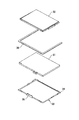
図6はピント板31とSI板32を分解して示している。矩形の枠体であるピント板枠33は、後端部34においてミラーボックス11(図1)の上端に枢支され、また前端に形成された係合部35において、ミラーボックス11の所定部位に係合可能である。ピント板31はピント板枠33に嵌め込まれる。ピント板31の上には、コの字型のピント調整ワッシャ36を介してSI板32が載置される。すなわちピント調整ワッシャ36によって、ピント板31とSI板32の間に所定の大きさの間隙が設けられ、これらは重合した状態で、ピント板枠33によって支持され、ミラーボックス11の上端に固定される。
【0019】
図7はSI板32を拡大して示す斜視図である。SI板32は合成樹脂から一体的に成形される透明部材である。SI板32は平行平面板37と、この平行平面板37を囲繞する外枠38とを有し、外枠38の短辺の外周面にはリブ39が形成される。平行平面板37は外枠38に対して角度θ(例えば1〜3°)だけ傾斜している。すなわち平行平面板37は、ピント板31よりも、撮影光学系側(図1および図2において左側)が相対的に低くなるように傾斜している。
【0020】
図8は、SI板32を下方から見たときのSI板32の中央付近を拡大して示し、図4の中央部分の拡大図でもある。すなわち図8における左側は、撮影者がファインダ画面の左側に対応する。
【0021】
SI板32の下面には、多数の微小プリズム52a、52bが突出して形成されており、微小プリズムの外形はSI板32を上あるいは下から見ると細長い台形である。微小プリズムは後述するように横断面が三角形を呈し、各微小プリズムの稜線51c、52c、53cはファインダ画面の左右方向に平行である。換言すれば、各微小プリズムの長手方向はファインダ画面において左右方向に一致している。微小プリズムは本実施形態において11個の群を構成しており、各微小プリズム群51〜61は、ファインダ画面に表示される合焦マークM(図4)に対応している。すなわち各合焦マークMは複数の微小プリズムの集合によって構成される。
【0022】
ファインダ画面において、第1微小プリズム群51は最も左側に位置している。第2、第3および第4微小プリズム群52、53、54は第1微小プリズム群51の右側に位置している。第5、第6および第7微小プリズム群55、56、57は全体の中央に位置している。第8、第9および第10微小プリズム群58、59、60は、その右側に位置し、第11微小プリズム群61は最も右側に位置している。
【0023】
第2微小プリズム群52を例にとって、その構成を説明する。第2微小プリズム群52は複数の微小プリズムによって構成され、相対的に大きい第1の微小プリズム52aと相対的に小さい第2の微小プリズム52bとを有している。
【0024】
第1の微小プリズム52aは、図8において左右方向に3つ並んで第1のプリズム列R1を形成している。第1のプリズム列R1において、隣接する微小プリズム52a同士は互いに接している。すなわち中央に位置する微小プリズム52aの台形の上底は左側に隣接する微小プリズム52aの台形の下底に接しており、また中央に位置する微小プリズム52aの台形の下底は右側に隣接する微小プリズム52aの台形の上底に接している。
【0025】
第1のプリズム列R1は4つ設けられ、各第1のプリズム列R1の間に形成される隙間には、第2の微小プリズム52bから成る第2のプリズム列R2が設けられている。第2の微小プリズム列R2は2つの第2の微小プリズム52bを図8において左右方向に2つ並べて構成され、左側に位置する微小プリズム52bの台形の下底は右側に隣接する微小プリズム52bの台形の上底に接している。
【0026】
第2の微小プリズム52bは、第1のプリズム列R1の隣接する2つの第1の微小プリズム52aの間に対応した位置に設けられ、第2の微小プリズム52bの台形の斜辺は、第1の微小プリズム52aの台形の下底の端点に接している。同様に、第2の微小プリズム52bの台形の下底の端点は、第1の微小プリズム52aの台形の斜辺に接している。すなわち、微小プリズム52a、52bは千鳥状に配置されている。
【0027】
図9および図10は、第2微小プリズム群52を示している。図9は図8のIX−IX線に沿う横断面図、図10は図8のX−X線に沿う縦断面図である。第1および第2の微小プリズム52a、52bの横断面の形状は略二等辺三角形であり、上方から照射された入射光は微小プリズム52a、52bにおいて反射し、入射光に対して平行に戻る。なお、各微小プリズム52a、52bの三角形の頂角は共に約90°である。
【0028】
第1の微小プリズム52aの反射面の稜線52cは、図10から理解されるように、SI板32の下面32aに対して傾斜している。この傾斜角αは、ルーフペンタ21のダハ反射面41から照射された照明光C2(図2)を、効率よく受光できるように定められている。照明光C2は図8において符号C3で示す光源対応位置の上方からSI板32に対して照射される。したがって、光源対応位置C3から離間するほど照射光のビームは大きく傾斜する。
【0029】
すなわち、各微小プリズム群における稜線の傾斜角αに関し、第1微小プリズム群51が最も大きい。第2、第3および第4微小プリズム群52、53、54の傾斜角αは相互に等しく、第1微小プリズム群51の傾斜角αよりも小さい。第5、第6および第7微小プリズム群55、56、57の傾斜角αも相互に等しく、第2、第3および第4微小プリズム群52、53、54の傾斜角αよりも小さい。第8、第9および第10微小プリズム群58、59、60の傾斜角αも相互に等しく、第5、第6および第7微小プリズム群55、56、57の傾斜角αよりも小さい。
【0030】
第11微小プリズム群61は、光源対応位置C3を挟んで第9微小プリズム群59の反対側に位置している。したがって第11微小プリズム群61の傾斜角αは第8、第9および第10微小プリズム群58、59、60の傾斜角αとは逆向きであり、大きさは略等しい。
【0031】
以上のように、第1〜第11微小プリズム群51〜61の稜線の傾斜角αの大きさは全部で5種類である。また傾斜角αは、ファインダ画面の左右方向の位置によって異なり、ファインダ画面において上下方向に並ぶ複数の微小プリズム群(例えば微小プリズム群52、53、54)の稜線の傾斜角αは同じである。
【0032】
このようにSI板32の下面32aには、光源25から投光されて照明光を受光する部位に、微小プリズム群51〜61が形成され、これらは合焦マークMに対応している。撮影動作において、撮影光学系が被写体のいずれかの点において合焦すると、その点に対応したLED27(図5)が点灯する。このLED27から出力された照明光C2(図2)によって、対応する微小プリズム群51〜61すなわち合焦マークMが照明されて赤く光るので、撮影者は合焦点を認識することができる。
【0033】
なお図8において、第2〜第5微小プリズム群51〜55と第7〜第10微小プリズム群57〜60はそれぞれ、正方形状を成すように構成され、第6微小プリズム群56は枠状を成すように構成されており、また第1および第11微小プリズム群51、61は長方形状を呈しているが、これらの形状は目的に応じて自由に変形することができる。
【0034】
多数の微小プリズムを有するSI板32を製造するための成形金型は、樹脂成形用の金型に刃物の先端を押し付けることによって得られる。刃物は微小プリズムを成形するためであり、その先端は断面形状が三角形を有し、また先端の表面は鏡面加工されている。例えば第2微小プリズム群52に対応した部分は、先端が第1の微小プリズム52aと同じ形状を有する刃物を金型に押し付けることによって成形される。すなわち、第1の微小プリズム52aの対応部分は所定の深さまで刃物を押し付け、第2の微小プリズム52bの対応部分は、第1の微小プリズム52aよりも浅く刃物を押し付ければよい。
【0035】
上述したように微小プリズムの傾斜角αの大きさは全部で5種類である。したがって刃物も5種類だけ製造すればよく、例えば第2、第3および第4微小プリズム群52、53、54に関しては、傾斜角αが共通であるので、同じ形状の刃物が使用される。
【0036】
図11は微小プリズム群の変形例を示している。この微小プリズム群62では、図8に示される第2微小プリズム群52と比較することから明らかなように、全ての微小プリズム62aは同じ形状および大きさを有している。すなわち、第1のプリズム列R3を構成する3つの微小プリズム62aは、第2のプリズム列R4を構成する2つの微小プリズム62aと同じ大きさを有している。第2のプリズム列R4は2つの第1のプリズム列R3の間に設けられ、第2のプリズム列R4の各微小プリズム62aは、第1のプリズム列R3の隣接する2つの微小プリズム62aの間に対応した位置に設けられている。すなわち、各微小プリズム62aは千鳥状に配置されている。その他の構成は第2の微小プリズム群52と同様である。
【0037】
以上のように本実施形態では、ルーフペンタ21の射出口22の上部に光源25を、また下部に投光プリズム26を設け、光源25から出射された照明光を投光プリズム26において反射させ、射出口22からルーフペンタ21内に導いている。したがって撮影動作時、被写体上のいずれかの点において合焦したことが合焦センサによって検出され、その合焦点に対応したLED27が点灯すると、照明光は第3反射面42とダハ反射面41において反射し、SI板32に導かれて所定の微小プリズム群が照明される。
【0038】
本実施形態では、微小プリズムの傾斜角αが5種類だけであり、微小プリズム群毎に傾斜角を変化させる必要がない。したがって、SI板32の製造工程が簡単化され、その管理が簡単になり、製造コストを抑えることができる。
【0039】
【発明の効果】
以上のように本発明によれば、微小プリズムの傾斜角の種類を極力少なくすることによって、微小プリズムの製造を簡単化することができる。
【図面の簡単な説明】
【図1】ミラーボックスとファインダ光学系を示し、投光プリズムを取り外した状態の断面図である。
【図2】ミラーボックスとファインダ光学系を示し、接眼光学系を取り外した状態の断面図である。
【図3】ルーフペンタを後側から見た斜視図である。
【図4】SI板に形成された合焦マークの配置を示す図である。
【図5】光源を示す断面図である。
【図6】ピント板とSI板を分解して示す斜視図である。
【図7】SI板を拡大して示す斜視図である。
【図8】SI板の中央付近を拡大して示す平面図である。
【図9】図8のIX−IX線に沿う横断面図である。
【図10】図8のX−X線に沿う縦断面図である。
【図11】微小プリズム群の変形例を示す平面図である。
【符号の説明】
21 ルーフペンタ
31 ピント板
32 スーパーインポーズ板
51c、52c、53c 稜線
52a、52b、62a 微小プリズム
M 合焦マーク[0001]
BACKGROUND OF THE INVENTION
The present invention relates to a light projecting device for displaying, for example, a focal point in a finder of a single-lens reflex camera.
[0002]
[Prior art]
In conventional single-lens reflex cameras, a superimpose display function is provided to display multiple focus points on the shooting screen and display the position of the focused point at these focus points on the subject image in the viewfinder. Are known (for example, Patent Document 1). In other words, if the focus plate and superimpose plate are superposed on the lower side of the pentamirror, and the number of focusable points is seven, the superimpose plate has seven small focus marks. Is formed. A projection optical system is disposed above the eyepiece optical system on the back surface of the pentamirror, that is, at the exit port. When a point on the subject is focused in the shooting operation, illumination light is emitted from the projection optical system. Is irradiated to the corresponding in-focus mark, and the photographer can recognize the in-focus point.
[0003]
Each focusing mark formed on the superimpose plate is composed of a large number of microprisms, and the microprisms are inclined with respect to the surface of the superimposing plate at an inclination angle corresponding to the position of the focusing mark. In other words, illumination light is emitted obliquely from the light source of the projection optical system provided on the exit side of the pentamirror, and the illumination angle of this illumination light varies greatly depending on the position of the focus mark, and the microprisms efficiently use the illumination light. Tilt at an angle that allows good light reception.
[0004]
[Patent Document 1]
Japanese Patent Laid-Open No. 2002-268128
[Problems to be solved by the invention]
As described above, when the inclination angle of the micro prism is different for each in-focus mark, the manufacturing becomes complicated, and it becomes difficult not only to manage the manufacturing process but also to increase the manufacturing cost.
[0006]
The present invention aims to simplify the manufacture of microprisms by reducing the type of tilt angle of the microprisms.
[0007]
[Means for Solving the Problems]
The superimposing plate of the finder according to the present invention includes a plurality of microprisms formed on the surface, and each of the plurality of microprisms has a triangular cross section, and the apex angle of the triangle is the same for all the microprisms. And the ridgeline of each microprism is parallel to the horizontal direction of the finder screen.
[0008]
A microprism group constituted by a plurality of microprisms corresponds to, for example, one mark displayed on the finder screen. The microprism group may include a relatively large first microprism and a relatively small second microprism, but may include microprisms of the same size. The external shape of the micro prism is, for example, a trapezoid when the superimpose plate is viewed from above.
[0009]
The ridge line is preferably inclined with respect to the surface of the superimposing plate. In addition, when a plurality of micro prism groups each including a plurality of micro prisms are provided, the inclination angle of the ridge lines of the plurality of micro prism groups varies depending on the position of the finder screen in the left-right direction, and in the vertical direction on the finder screen. It is preferable that the inclination angles of the ridgelines of the plurality of arranged microprism groups are the same.
[0010]
DETAILED DESCRIPTION OF THE INVENTION
Hereinafter, an embodiment of the present invention will be described with reference to the drawings. 1 and 2 are cross-sectional views of a mirror box and a finder optical system of a single-lens reflex camera. FIG. 1 shows a state where a projection prism is removed, and FIG. 2 shows a state where an eyepiece optical system is removed. FIG. 3 is a perspective view of the roof penta seen from the rear side, that is, the eyepiece optical system side.
[0011]
An
[0012]
At the entrance of the
[0013]
The
[0014]
A
[0015]
The exit surface of the
[0016]
FIG. 4 shows the arrangement of the focus marks M formed on the
[0017]
The
[0018]
FIG. 6 shows the focusing
[0019]
FIG. 7 is an enlarged perspective view showing the
[0020]
Figure 8 is an enlarged view of a vicinity of the center of
[0021]
A large number of
[0022]
In the viewfinder screen, the
[0023]
The configuration of the
[0024]
The
[0025]
Four first prism rows R1 are provided, and a second prism row R2 including a
[0026]
The
[0027]
9 and 10 show the
[0028]
The ridgeline 52c of the reflection surface of the
[0029]
That is, the
[0030]
The
[0031]
As described above, the sizes of the inclination angles α of the ridge lines of the first to
[0032]
Thus, on the
[0033]
In FIG. 8, the second to fifth
[0034]
A molding die for manufacturing the
[0035]
As described above, the inclination angle α of the micro prism has five types in total. Accordingly, only five types of blades need to be manufactured. For example, the second, third, and
[0036]
FIG. 11 shows a modification of the small prism group. In this
[0037]
As described above, in the present embodiment, the
[0038]
In the present embodiment, there are only five types of inclination angles α of the micro prisms, and there is no need to change the inclination angle for each micro prism group. Therefore, the manufacturing process of the
[0039]
【The invention's effect】
As described above, according to the present invention, it is possible to simplify the manufacture of the microprisms by reducing the types of inclination angles of the microprisms as much as possible.
[Brief description of the drawings]
FIG. 1 is a cross-sectional view showing a mirror box and a viewfinder optical system, with a projection prism removed.
FIG. 2 is a cross-sectional view showing a mirror box and a finder optical system, with an eyepiece optical system removed.
FIG. 3 is a perspective view of the roof penta viewed from the rear side.
FIG. 4 is a diagram showing an arrangement of focusing marks formed on an SI plate.
FIG. 5 is a cross-sectional view showing a light source.
FIG. 6 is an exploded perspective view showing a focus plate and an SI plate.
FIG. 7 is an enlarged perspective view showing an SI plate.
FIG. 8 is an enlarged plan view showing the vicinity of the center of the SI plate.
9 is a transverse sectional view taken along line IX-IX in FIG.
10 is a longitudinal sectional view taken along line XX of FIG.
FIG. 11 is a plan view showing a modification of the microprism group.
[Explanation of symbols]
21
Claims (6)
表面に形成された複数の微小プリズムを備え、前記複数の微小プリズムはそれぞれ、横断面が三角形を成し、前記三角形の頂角は全ての微小プリズムにおいて同一であり、かつ各微小プリズムの稜線は前記ファインダ画面の左右方向に平行であり、
前記稜線は前記スーパーインポーズ板の表面に対して傾斜しており、
前記複数の微小プリズムによって構成される微小プリズム群が複数設けられ、前記ファインダ画面において上下方向に並ぶ複数の微小プリズム群の稜線の傾斜角は同じであることを特徴とするファインダのスーパーインポーズ板。A superimpose plate provided by being superimposed on a focus plate on which an object image obtained by a photographing optical system is formed at an entrance of a roof penta;
A plurality of microprisms formed on the surface, each of the plurality of microprisms has a triangular cross section, the apex angle of the triangle is the same in all the microprisms, and the ridgeline of each microprism is Ri parallel der in the lateral direction of the finder screen,
The ridge line is inclined with respect to the surface of the superimposing plate,
A finder superimpose plate , wherein a plurality of microprism groups each including the plurality of microprisms are provided, and the ridge lines of the plurality of microprism groups arranged in the vertical direction on the finder screen have the same inclination angle. .
Priority Applications (2)
| Application Number | Priority Date | Filing Date | Title |
|---|---|---|---|
| JP2003009663A JP3911239B2 (en) | 2003-01-17 | 2003-01-17 | Finder superimpose board |
| US10/759,022 US7046925B2 (en) | 2003-01-17 | 2004-01-20 | Superimpose-plate for view finder |
Applications Claiming Priority (1)
| Application Number | Priority Date | Filing Date | Title |
|---|---|---|---|
| JP2003009663A JP3911239B2 (en) | 2003-01-17 | 2003-01-17 | Finder superimpose board |
Publications (3)
| Publication Number | Publication Date |
|---|---|
| JP2004219916A JP2004219916A (en) | 2004-08-05 |
| JP2004219916A5 JP2004219916A5 (en) | 2005-10-27 |
| JP3911239B2 true JP3911239B2 (en) | 2007-05-09 |
Family
ID=32899094
Family Applications (1)
| Application Number | Title | Priority Date | Filing Date |
|---|---|---|---|
| JP2003009663A Expired - Fee Related JP3911239B2 (en) | 2003-01-17 | 2003-01-17 | Finder superimpose board |
Country Status (1)
| Country | Link |
|---|---|
| JP (1) | JP3911239B2 (en) |
Families Citing this family (1)
| Publication number | Priority date | Publication date | Assignee | Title |
|---|---|---|---|---|
| WO2011070817A1 (en) * | 2009-12-09 | 2011-06-16 | 株式会社村田製作所 | Device for spectrometry having void-arranged structure held thereto, frame member used for same, and spectrometer |
-
2003
- 2003-01-17 JP JP2003009663A patent/JP3911239B2/en not_active Expired - Fee Related
Also Published As
| Publication number | Publication date |
|---|---|
| JP2004219916A (en) | 2004-08-05 |
Similar Documents
| Publication | Publication Date | Title |
|---|---|---|
| US6941069B2 (en) | Light-projecting device | |
| US7548688B2 (en) | Optical apparatus | |
| JP3920781B2 (en) | Finder projector | |
| JP3947474B2 (en) | Finder superimpose board | |
| JP3911239B2 (en) | Finder superimpose board | |
| US6903885B2 (en) | Light-projecting device | |
| JP4324997B2 (en) | camera | |
| JP4576155B2 (en) | Viewfinder display device | |
| US7046925B2 (en) | Superimpose-plate for view finder | |
| US7280751B2 (en) | In-finder display device | |
| JP4566804B2 (en) | Display device in viewfinder and camera having the same | |
| JP2005037493A (en) | Display device for optical apparatus | |
| JP2503519Y2 (en) | Information display device | |
| JP2004219909A (en) | Light projection device for finder | |
| JP2004219885A (en) | Light projector for finder | |
| JP2002055384A (en) | Finder device and camera using the same | |
| JPH0274936A (en) | Single-lens reflex camera body for executing display in finder | |
| JP2012093628A (en) | Finder internal display device for camera | |
| US20100027985A1 (en) | In-finder display apparatus | |
| JP5665506B2 (en) | Imaging device | |
| JP4324995B2 (en) | camera | |
| JP4418607B2 (en) | Viewfinder display device | |
| JP4324996B2 (en) | camera | |
| JP4335638B2 (en) | Camera viewfinder lighting device | |
| JP5418880B2 (en) | Display device and optical apparatus provided with the same |
Legal Events
| Date | Code | Title | Description |
|---|---|---|---|
| A521 | Request for written amendment filed |
Free format text: JAPANESE INTERMEDIATE CODE: A523 Effective date: 20050819 |
|
| A621 | Written request for application examination |
Free format text: JAPANESE INTERMEDIATE CODE: A621 Effective date: 20050819 |
|
| A977 | Report on retrieval |
Free format text: JAPANESE INTERMEDIATE CODE: A971007 Effective date: 20061005 |
|
| A131 | Notification of reasons for refusal |
Free format text: JAPANESE INTERMEDIATE CODE: A131 Effective date: 20061031 |
|
| A521 | Request for written amendment filed |
Free format text: JAPANESE INTERMEDIATE CODE: A523 Effective date: 20061208 |
|
| TRDD | Decision of grant or rejection written | ||
| A01 | Written decision to grant a patent or to grant a registration (utility model) |
Free format text: JAPANESE INTERMEDIATE CODE: A01 Effective date: 20070116 |
|
| A61 | First payment of annual fees (during grant procedure) |
Free format text: JAPANESE INTERMEDIATE CODE: A61 Effective date: 20070126 |
|
| R150 | Certificate of patent or registration of utility model |
Free format text: JAPANESE INTERMEDIATE CODE: R150 |
|
| FPAY | Renewal fee payment (event date is renewal date of database) |
Free format text: PAYMENT UNTIL: 20110202 Year of fee payment: 4 |
|
| FPAY | Renewal fee payment (event date is renewal date of database) |
Free format text: PAYMENT UNTIL: 20120202 Year of fee payment: 5 |
|
| FPAY | Renewal fee payment (event date is renewal date of database) |
Free format text: PAYMENT UNTIL: 20120202 Year of fee payment: 5 |
|
| S111 | Request for change of ownership or part of ownership |
Free format text: JAPANESE INTERMEDIATE CODE: R313111 |
|
| FPAY | Renewal fee payment (event date is renewal date of database) |
Free format text: PAYMENT UNTIL: 20120202 Year of fee payment: 5 |
|
| R350 | Written notification of registration of transfer |
Free format text: JAPANESE INTERMEDIATE CODE: R350 |
|
| FPAY | Renewal fee payment (event date is renewal date of database) |
Free format text: PAYMENT UNTIL: 20130202 Year of fee payment: 6 |
|
| S533 | Written request for registration of change of name |
Free format text: JAPANESE INTERMEDIATE CODE: R313533 |
|
| R350 | Written notification of registration of transfer |
Free format text: JAPANESE INTERMEDIATE CODE: R350 |
|
| LAPS | Cancellation because of no payment of annual fees |