JP3910071B2 - Internal stopper mechanism for liquid containers - Google Patents
Internal stopper mechanism for liquid containers Download PDFInfo
- Publication number
- JP3910071B2 JP3910071B2 JP2002014008A JP2002014008A JP3910071B2 JP 3910071 B2 JP3910071 B2 JP 3910071B2 JP 2002014008 A JP2002014008 A JP 2002014008A JP 2002014008 A JP2002014008 A JP 2002014008A JP 3910071 B2 JP3910071 B2 JP 3910071B2
- Authority
- JP
- Japan
- Prior art keywords
- lid
- liquid
- valve
- shoulder member
- operating rod
- Prior art date
- Legal status (The legal status is an assumption and is not a legal conclusion. Google has not performed a legal analysis and makes no representation as to the accuracy of the status listed.)
- Expired - Fee Related
Links
Images


Description
【0001】
【発明の属する技術分野】
本発明は液体容器の開口に装着する中栓であって、中栓そのものに液通路を形成するとともに液通路を開閉する弁を設け、該弁を開閉することによって中栓を装着した状態で注液することができる液体容器の中栓機構、特に中栓から流出する注液部分の上方を覆う蓋を備えた中栓機構に関する発明である。
【0002】
【従来の技術】
魔法びんなどの液体容器の開口に装着する中栓には、図9に示すように中栓Aの内部に弁Bを備えた液通路Cを形成し、弁の開閉によって中栓を装着した状態で液体容器全体を傾けることによって、液体容器の肩部材Dに形成した注液口Eから注液可能とするものが知られている。液通路Cに配置した弁Bは、バネJによって常時液通路を閉鎖する方向に付勢されており、操作部Kを手指で操作することによって弁を開放する。操作部Kは係止手段を備えており、一旦弁を開放すると、次に操作を行うまでその状態を維持する。なお、図9に示す液体容器は内容器として真空二重びんGを使用する魔法びんであり、肩部材Dと一体に把手Fを形成している。
図10に示す従来の液体容器は、開口部分に着脱可能な中栓Aを装着し、その上方を水平方向の軸Hによって回動する蓋Iによって覆っている。
図11に示す従来の液体容器用中栓は、前方部分を支点として回動するレバーLを設け、このレバーLによって弁Bを押し下げ、液通路Cを開放することができるようにしている。
【0003】
また、実開昭61-184546号公報に開示されるように、中栓から流出する内容液の注液部分上方を覆う蓋を配置し、蓋の水平方向の動きに連動させて弁を開閉する思想も知られている。さらに、実開昭51-109459号に開示されるように、弁機構を備えていない中栓の内部に液通路を形成し、液通路を延長した注液パイプの先端部分を注液口とするとともに、注液口を水平方向に軸支される蓋によって開閉する思想が知られている。
【0004】
【発明が解決しようとする課題】
実開昭61-184546号公報に開示される従来の液体容器の中栓機構は、蓋あるいはカバーを常に水平方向に移動させることによって注液部分の上方を開閉するとともに、カム機構によって蓋の水平方向の移動と中栓の弁の動きを連動させている。したがって、蓋を開けて注液可能な状態にするには、常に両手による操作を必要とし、注ぎ終わって液体容器を置いた後にもう一度蓋を閉じる動作をしなければならないという不便さがあった。実開昭51-109459号に開示される中栓構造では、例えば取っ手を握った手の指で蓋を開閉させて注液することができるが、中栓の液通路は常に開放された状態であるため転倒などに際して液漏れを生じるといった不具合がある。
【0005】
上記、従来の液体容器の中栓機構の欠点に鑑み、本発明は内部に液通路を形成し、液体容器から取らずに注液することができる中栓であって、注液部分の上方を覆う蓋の開閉操作を片手で行うことができ、蓋の開閉操作に連動させて液通路に設けた弁を開閉し、液体容器を片手で持ち、指で蓋を開けるだけで注液し、かつ注液後には自然に衝撃のない状態で蓋が閉じて液通路が閉鎖され、安全で使い易い液体容器の中栓機構を提供することを目的とするものである。
【0006】
【課題を解決するための手段】
上記目的を達成するため本発明は、バネ13によって液通路11を常時閉鎖する方向に付勢される弁12を備えた中栓の一部に、注液部分の上方を覆う蓋16を水平方向の軸17により軸支し、該水平方向の軸17を中心として回動する蓋 16 の軸支位置よりも背面方向部分の手指操作によって、蓋の前端部分で注液口 15 を開閉自在とする。
【0007】
前記弁 12 の弁杆 12a は上方に突出させる。そして、蓋 16 を軸支する軸 17 と弁杆 12a の中間位置に、中栓の一部に軸支させてシーソー運動をする作動杆 19 を配置し、作動杆 19 の一部を蓋 16 に係合させることによって、蓋 16 の開閉動作に作動杆 19 を連動させ、作動杆 19 によって上方に突出している弁杆 12a を押し下げて注液可能な状態とする。
【0008】
作動杆 19 に上方へ突出するバネ片 21 を形成して蓋 16 の裏面に当接させる。蓋 16 の裏面には、蓋が注液部分を閉鎖する直前位置において、作動杆 19 に形成したバネ片 21 が当接し、かつ乗り越えることによって抵抗となる突起 22 を形成し、衝撃的に蓋が閉まるのを防止する。
【0009】
【発明の実施の形態】
以下、本発明に係る液体容器の中栓機構の実施形態を、添付の図面に基づいて説明する。
図1は本発明に係る中栓機構を備えた液体容器の一例として真空二重びんを使用する魔法びんの縦断面図、図2は図1の上部のみの拡大図である。
【0010】
図1に示す液体容器は、外胴1の内部に液体容器2として真空二重びんを配置し、外胴1の上端に肩部材3を装着するとともに肩部材3によって液体容器2の上端部を保持させている。4は肩部材に螺着し外胴の上端に肩部材を保持させるための締め上げ環であり、肩部材3に別に成型した把手5を装着している。肩部材の中心部分には、液体容器の開口と対応する開口7を形成し、この開口7に中栓6を装着している。すなわち、肩部材の上面に大径の凹所8を形成し、該凹所8に中栓6を螺着することによって開口7を密閉する。
【0011】
肩部材に螺着する中栓6は開口7に入り込む小径部6aと、肩部材3の凹所8に嵌まり込む大径部6bが形成され、大径部6bに形成した雄ネジと凹所8に形成した雌ネジを螺合させ、小径部6aの基部に装着したパッキン9が開口7部分に押圧されて密接することによって液体容器の密閉状態が実現する。中栓の上端は肩部材の上面から突出し、該突出部分に肩部材の外形と一致させて体裁を整えた栓カバー10を固着している。
【0012】
開口7に入り込む小径部6aは筒状であって、その内部を液通路11とするとともに小径部6aの下端開口部分に、液通路11を閉鎖する弁12を配置している。弁12の弁杆12aは、中栓6の中心筒6cを貫通しその上端部分が上方に突出している。弁12そのものは、小径部の内径よりも大きな円板状であってバネ13によって上方に付勢することで液通路11の下端開口部分に下から密着させ常時液通路を閉鎖している。換言すれば、上方に突出している弁杆12aを押し下げることによって、液通路の下端開口を閉鎖している弁が下方に移動し、中栓6の小径部6a下端開口が開放されるものである。
【0013】
中栓6の上端部に固着される栓カバー10は、構造上中栓6と別体で成型し、組み立てによって一体化している。このような栓カバー10に、中栓6の液通路11を延長させる態様で注液パイプ14を形成し、その先端部分を注液口15とする。中栓6の上面を覆う栓カバー10のうち注液パイプ14を含み、中心を通る前後方向に天壁を省略して中央溝部分を形成し、この中央溝の上方を覆う如く一定幅の板状であるレバー形状に形成した蓋16を配置する。
【0014】
レバー形状の蓋16は、弁杆12aよりも背面寄りの位置において水平方向の軸17によって中栓6もしくは中栓と一体的である中栓カバー10に軸着し、軸17よりも背面方向の部分を押すことにより正面側の部分を持ち上げることができるようにしている。すなわち、レバー形状の背面部分に形成されているレバー部16aを、把手5を持った手の親指などで操作することにより、軸17を中心として上下方向に回動させ、注液パイプ14先端の注液口15を覆っている蓋前端部分を開放し、液体容器全体を傾けることによって注液を可能とする。蓋16を軸支する軸17は、必ずしも貫通する一本の軸である必要はなく、図示していないが、栓カバー10の一部に形成された凹所に枢着するべき枢軸とすることができる。
【0015】
蓋16を支持する軸17と弁杆12aの中間位置に、前記軸17と平行な方向の軸18によって軸支されてシーソー運動を行う作動杆19を配置する。シーソー運動を行う作動杆19の、軸18よりも背面側の先端部分は、軸17と18の中間位置において蓋16の一部に形成した操作爪20に係合させるとともに、作動杆19の軸18よりも正面側の部分を弁杆12aの上方に接近させて配置している。したがって、図3に示すように蓋16のレバー部16aを押し下げ、図面上右方向に回動させて蓋を開くと、蓋16の操作爪20によって作動杆19の軸18よりも右端側が持ち上げられて左方向に回動する。作動杆19が左方向に回動すると、軸18よりも左側(正面側)が下がり弁杆12aの上端に当接する。そして、蓋16を開ける力によってバネ13の力に抗して弁杆12aを押し下げ液通路11の入り口である中栓下端を開放する。
【0016】
注液後、蓋16のレバー部16aの押圧を開放すると、バネ13の弾発力によって作動杆19が押し戻されて図面上右方向に回動し、この作動杆19の回動によって蓋16に形成した操作爪20を押し下げ、蓋16が自然に閉鎖される。このとき、作動杆19及び蓋16が自由に回動し得る状態であると、使用者の意思に反して蓋16が勢い良く閉じてしまうことになる。この問題を解決するため、蓋の開閉動作に対して注液部分の上方を閉鎖する直前位置において抵抗を与える抵抗手段を設けることにより、蓋16は静かに閉じられる。
【0017】
前記抵抗手段について、図1ないし図3に示す実施形態では、作動杆19に上方へ突出するバネ片21を形成し、このバネ片21を蓋16の裏面に当接させるとともに、蓋が注液部分の上方を閉鎖する直前位置においてバネ片21が当たる突起22を蓋の裏面に形成している。これにより、バネ片21が突起22を乗り越えるときに抵抗力が発生し、蓋が衝撃的に閉じられるのを防止している。なお、作動杆19を合成樹脂材で成型する場合は、単にバネ片21を一体成型することによって樹脂バネを形成することができる。
【0018】
従来の液体容器、主としてハンドポットタイプの魔法びんでは、肩部材に把手を一体に成型するものが広く普及している。ところが、このようなものでは金型が大型となるとともに、成型材料としてハンドルの強度と肩部材としての精度などを備えた材質のものを選択する必要がありコストアップの一因となっている。また、把手を肩部材と離れた位置の胴にビス止めするものも知られているが、このようなものでは肩部材との一体感がなく、デザイン的には全く違った印象を与える製品である。
【0019】
上記従来の肩部材に把手が一体に成型される形態の製品に対して、図示実施形態の液体容器は、別部品として成型した肩部材3と把手5を簡単な構造で固定する構造を採用している。肩部材3と把手5の取付け構造として図4ないし図8に三つの取付け構造を例示している。
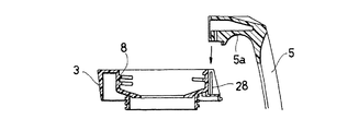
図4、図5に示す構造は、肩部材3の背面上部に切欠凹所27を形成するとともに、ハンドル5の上端に前記切欠凹所27に嵌まり込む形状の嵌合部5aを形成し、切欠凹所27の左右内側面に垂直方向のリブ28を形成するとともに、ハンドル5の嵌合部5a側面にリブ28が嵌まり込む凹溝29を設けている。このハンドル構造を組み立てるには、肩部材に形成した切欠凹所27のリブ28をハンドル5に形成した凹溝29に嵌め込んだ状態でハンドル5の嵌合部5aを切欠凹所27に挿入し、肩部材の下方からビス30で固定する。この構造とすることによって、リブと凹溝の嵌合によって前後左右の動きが規制され、ビス30止めすることによってハンドルの取付け強度を向上させることができる。
【0020】
図6及び図7に示す構造は、肩部材5の背面上部に背面方向に向けて左右一対の掛け爪31,31を突出させるとともに、把手5の上部先端部分に水平方向の嵌合孔32を穿設し、嵌合孔32の左右両側壁に係止部を設けている。この形態は、肩部材の掛け爪31をハンドル5の嵌合孔32に挿入し、掛け爪31を係止部33に係合させた状態で肩部材3の下方からビス30で両者を固定する。また、掛け爪31の座31a部分が少し突出し、この座31a部分が嵌合孔32に嵌まり込むことによって、ガタツキを防止する効果を向上させる。上記、図6及び図7に示す実施形態に係るハンドル取付け構造では、掛け爪による係止強度及び係止方向と、ビス30による係止強度及び係止方の相乗的な取付け強度によってハンドルが肩部材に強固に固定される。
【0021】
図8に示す実施形態は、肩部材3の背面に水平方向の嵌合筒34を突出成型するとともに、把手の前端面から背面方向に向けて嵌合孔35を形成し、嵌合筒34と嵌合孔35が比較的緊密に嵌合するようにしたものである。嵌合筒34と嵌合孔35が嵌合することによって筒方向、すなわち正背面方向の移動以外の動きが規制され、かつビス30によって、前記正背面方向の動きが確実に規制され、しっかりと固定される。
以上述べたように、図4ないし図8に記載した肩部材3と把手5の取付け構造は、別部材として成型した肩部材3と把手5を保持方向が異なる複合的な係止手段によって結合させて組み立てるため、ガタツキなく強固に組み立てることができるとともに肩部材3と把手5をそれぞれに好ましい材質を選定して成型することができる。
【0022】
【発明の効果】
請求項1記載の本発明液体容器の中栓機構によれば、液体容器を持った手の指で操作することによって注液部分の上方を覆う蓋を開閉させ、蓋の開閉に連動させて中栓の液通路を閉鎖している弁を開放させることができる。したがって、常時液通路を閉鎖する中栓を備えた液体容器を片手で持って、そのまま傾けることによって注液することができ、注液後に手を離せば弁機構のバネの力で弁と蓋が閉じられるといった、取扱いに便利なものとすることができる。
【0023】
このとき、シーソー運動を行う作動杆を配置するという、比較的簡単な構造で実施することができるとともに、作動の際に中栓に内蔵されているバネの力によって、弁ひいては蓋が衝撃的に閉じられるようなことがなく、安心して使用することができる効果がある。
【0024】
【図面の簡単な説明】
【図1】本発明に係る中栓を装着した、液体容器全体の縦断面図、
【図2】図1に示す液体容器の上部のみの拡大断面図、
【図3】蓋を開けた状態の液体容器の上部のみの縦断面図、
【図4】肩部材と把手上部の分解斜視図、
【図5】図4の縦断面図、
【図6】図4とは別の肩部材と把手上部の分解斜視図、
【図7】図4の縦断面図、
【図8】肩部材と把手の別の取付け構造を備えた液体容器の上部のみの縦断面図、
【図9】従来の中栓機構を備えた液体容器の上部のみの縦断面図、
【図10】従来の蓋付きの一例を示す液体容器の上部のみの縦断面図、
【図11】従来の中栓の別の一例を示す縦断面図。
【符号の説明】
1…外胴、 2…液体容器、 3…肩部材、 4…締め上げ環、 5…把手、 6…中栓、 7…開口、 8…凹所、 9…パッキン、 10…栓カバー、 11…液通路、 12…弁、 13…バネ、 14…注液パイプ、 15…注液口、 16…蓋、 17,18…軸、 19 …作動杆、 20…操作爪、 21…バネ片、 22…突起、 27…切欠凹所、 28…リブ、 29…凹溝、 30…ビス、 31…掛け爪、 32…嵌合孔、 33…係止部、 34…嵌合筒、 35…嵌合孔。[0001]
BACKGROUND OF THE INVENTION
The present invention relates to an inner plug to be attached to the opening of a liquid container, wherein the inner plug itself has a liquid passage and a valve for opening and closing the liquid passage, and the inner plug is attached by opening and closing the valve. The invention relates to an inner stopper mechanism for a liquid container that can be liquefied, in particular, an inner stopper mechanism that includes a lid that covers an upper part of a liquid injection portion that flows out from the inner stopper.
[0002]
[Prior art]
As shown in FIG. 9 , a liquid passage C having a valve B is formed inside the inner stopper A, and the inner stopper is attached by opening and closing the valve. It is known that liquid can be injected from a liquid injection port E formed in a shoulder member D of the liquid container by tilting the entire liquid container. The valve B disposed in the liquid passage C is always urged by a spring J in a direction to close the liquid passage, and the valve is opened by operating the operation unit K with fingers. The operation unit K includes a locking means, and once the valve is opened, the state is maintained until the next operation is performed. The liquid container shown in FIG. 9 is a magic bottle that uses a vacuum double bottle G as an inner container, and a handle F is formed integrally with the shoulder member D.
The conventional liquid container shown in FIG. 10 is provided with a detachable inner plug A at the opening, and the upper part is covered with a lid I that is rotated by a horizontal axis H.
The conventional liquid container inner plug shown in FIG. 11 is provided with a lever L that rotates with the front portion as a fulcrum, and the lever B pushes down the valve B so that the liquid passage C can be opened.
[0003]
Further, as disclosed in Japanese Utility Model Publication No. 61-184546, a lid is provided to cover the top of the liquid injection portion of the content liquid flowing out from the inner plug, and the valve is opened and closed in conjunction with the horizontal movement of the lid. Thoughts are also known. Further, as disclosed in Japanese Utility Model Laid-Open No. 51-109459, a liquid passage is formed inside the inner plug not provided with a valve mechanism, and a tip portion of a liquid injection pipe extending the liquid passage is used as a liquid injection port. At the same time, the idea of opening and closing the liquid injection port with a lid pivotally supported in the horizontal direction is known.
[0004]
[Problems to be solved by the invention]
In the conventional stopper mechanism of a liquid container disclosed in Japanese Utility Model Laid-Open No. 61-184546, the lid or cover is always moved in the horizontal direction to open and close the upper part of the liquid injection portion, and the cam mechanism horizontally opens the lid. The movement of the direction is linked with the movement of the valve of the inner plug. Therefore, in order to open the lid and make it possible to inject liquid, it is necessary to always operate with both hands, and there is an inconvenience that after the pouring is finished and the liquid container is placed, the lid must be closed again. In the inner plug structure disclosed in Japanese Utility Model Publication No. 51-109459, for example, liquid can be injected by opening and closing the lid with the finger of the hand holding the handle, but the liquid passage of the inner plug is always open. Therefore, there is a problem that a liquid leaks during a fall.
[0005]
In view of the above drawbacks of the conventional stopper mechanism for liquid containers, the present invention is an inner stopper that forms a liquid passage inside and can be injected without taking it out of the liquid container. The cover can be opened and closed with one hand, the valve provided in the liquid passage is opened and closed in conjunction with the opening and closing of the cover, the liquid container is held with one hand, and the liquid can be injected simply by opening the cover with a finger, and An object of the present invention is to provide a safe and easy-to-use internal stopper mechanism for a liquid container, with the lid closed and the liquid passage closed in a state where there is no impact naturally after injection.
[0006]
[Means for Solving the Problems]
In order to achieve the above object, the present invention provides a horizontal cover with a
[0007]
The
[0008]
A
[0009]
DETAILED DESCRIPTION OF THE INVENTION
DETAILED DESCRIPTION OF THE PREFERRED EMBODIMENTS Embodiments of an internal stopper mechanism for a liquid container according to the present invention will be described below based on the attached drawings.
FIG. 1 is a longitudinal sectional view of a magic bottle using a vacuum double bottle as an example of a liquid container equipped with an inner stopper mechanism according to the present invention, and FIG. 2 is an enlarged view of only the upper part of FIG.
[0010]
In the liquid container shown in FIG. 1, a vacuum double bottle is disposed as a
[0011]
The
[0012]
The small-
[0013]
The
[0014]
The lever-
[0015]
At an intermediate position between the
[0016]
After the injection, when the
[0017]
In the embodiment shown in FIGS. 1 to 3, the resistance means is formed with a
[0018]
In conventional liquid containers, mainly hand pot type magic bottles, those in which a handle is formed integrally with a shoulder member are widely used. However, in such a case, the mold becomes large, and it is necessary to select a material having the strength of the handle and the accuracy as the shoulder member as a molding material, which causes an increase in cost. It is also known that the handle is screwed to the body at a position distant from the shoulder member, but with such a product there is no sense of unity with the shoulder member and it is a product that gives a completely different impression in terms of design. is there.
[0019]
In contrast to the conventional product in which the handle is integrally formed with the shoulder member, the liquid container of the illustrated embodiment employs a structure in which the
The structure shown in FIGS. 4 and 5 is formed with a
[0020]
6 and 7 , a pair of left and right hooking
[0021]
In the embodiment shown in FIG. 8 , a horizontal
As described above, the mounting structure of the
[0022]
【The invention's effect】
According to the inside stopper mechanism of the liquid container of the present invention, the lid covering the upper part of the liquid injection part is opened and closed by operating with the finger of the hand holding the liquid container, and the inside is interlocked with the opening and closing of the lid. A valve closing the liquid passage of the stopper can be opened. Therefore, it is possible to inject liquid by holding a liquid container equipped with an inner stopper that always closes the liquid passage with one hand and tilting it as it is. such as closed, Ru can be made more convenient to handle.
[0023]
At this time, of placing the actuating rod of performing seesaw motion, it is possible real Hodokosuru a relatively simple structure, by the force of a spring incorporated in the inside plug upon actuation, the valve thus lid shocking There is an effect that can be used with confidence without being closed.
[0024]
[Brief description of the drawings]
FIG. 1 is a longitudinal sectional view of an entire liquid container equipped with an inner stopper according to the present invention,
FIG. 2 is an enlarged cross-sectional view of only the upper part of the liquid container shown in FIG.
[Figure 3] a vertical section of only the upper portion of the liquid container in a state where the lid open view,
FIG. 4 is an exploded perspective view of the shoulder member and the upper part of the handle ,
FIG. 5 is a longitudinal sectional view of FIG.
6 is an exploded perspective view of a shoulder member and a handle upper part different from those in FIG . 4;
7 is a longitudinal sectional view of FIG.
FIG. 8 is a longitudinal sectional view of only the upper part of a liquid container having another mounting structure for a shoulder member and a handle;
FIG. 9 is a longitudinal sectional view of only the upper part of a liquid container equipped with a conventional inner stopper mechanism;
FIG. 10 is a longitudinal sectional view of only the upper part of a liquid container showing an example with a conventional lid;
FIG. 11 is a longitudinal sectional view showing another example of a conventional inner plug.
[Explanation of symbols]
DESCRIPTION OF
Claims (1)
前記弁の弁杆を上方に突出させるとともに、前記蓋を軸支する軸と弁杆の中間位置に中栓の一部に軸支させてシーソー運動をする作動杆を配置し、該作動杆の一部を蓋に係合させることによって蓋の開閉動作に作動杆を連動させ、該作動杆によって上方に突出している弁杆を押し下げて注液可能な状態とするとともに、
前記作動杆に上方へ突出するバネ片を形成して蓋の裏面に当接させ、蓋が注液部分を閉鎖する直前位置において、前記バネ片が乗り越えて抵抗となる突起を蓋の裏面に形成したことを特徴とする液体容器の中栓機構。A lid that covers the top of the liquid injection part is pivotally supported by a horizontal axis on a part of the inner plug provided with a valve that is biased in a direction that always closes the liquid passage by a spring, and the horizontal axis is the center. The liquid injection port can be opened and closed at the front end portion of the lid by finger operation in the back direction part from the pivotal support position of the rotating lid ,
An operating rod that makes the seesaw motion by pivotally supporting a part of the inner plug is disposed at a middle position between the shaft that pivotally supports the lid and the valve rod, and protruding the valve rod of the valve. By engaging a part with the lid, the operating rod is linked to the opening and closing operation of the lid, and the valve rod protruding upward is pushed down by the operating rod so that the liquid can be injected.
A spring piece projecting upward is formed on the operating rod and brought into contact with the back surface of the lid, and a projection is formed on the back surface of the lid that the spring piece gets over and resists just before the lid closes the liquid injection part. inside plug mechanism of the liquid container, characterized in that it has.
Priority Applications (1)
| Application Number | Priority Date | Filing Date | Title |
|---|---|---|---|
| JP2002014008A JP3910071B2 (en) | 2002-01-23 | 2002-01-23 | Internal stopper mechanism for liquid containers |
Applications Claiming Priority (1)
| Application Number | Priority Date | Filing Date | Title |
|---|---|---|---|
| JP2002014008A JP3910071B2 (en) | 2002-01-23 | 2002-01-23 | Internal stopper mechanism for liquid containers |
Publications (2)
| Publication Number | Publication Date |
|---|---|
| JP2003212260A JP2003212260A (en) | 2003-07-30 |
| JP3910071B2 true JP3910071B2 (en) | 2007-04-25 |
Family
ID=27650817
Family Applications (1)
| Application Number | Title | Priority Date | Filing Date |
|---|---|---|---|
| JP2002014008A Expired - Fee Related JP3910071B2 (en) | 2002-01-23 | 2002-01-23 | Internal stopper mechanism for liquid containers |
Country Status (1)
| Country | Link |
|---|---|
| JP (1) | JP3910071B2 (en) |
Families Citing this family (3)
| Publication number | Priority date | Publication date | Assignee | Title |
|---|---|---|---|---|
| JP6007424B2 (en) * | 2013-05-17 | 2016-10-12 | 象印マホービン株式会社 | Beverage container |
| JP6018563B2 (en) * | 2013-11-18 | 2016-11-02 | 象印マホービン株式会社 | Cooking device |
| HUP1600126A2 (en) | 2016-02-24 | 2017-08-28 | Zoltan Pethoe | Liquid dispensing cap |
-
2002
- 2002-01-23 JP JP2002014008A patent/JP3910071B2/en not_active Expired - Fee Related
Also Published As
| Publication number | Publication date |
|---|---|
| JP2003212260A (en) | 2003-07-30 |
Similar Documents
| Publication | Publication Date | Title |
|---|---|---|
| US5791525A (en) | Liquid soap dispenser | |
| JP2005193944A (en) | Stopper of drink container | |
| JP2003212258A (en) | Inner stopper for drink container | |
| WO1998056677A1 (en) | Cap for beverage container | |
| JP3910071B2 (en) | Internal stopper mechanism for liquid containers | |
| JP5333812B2 (en) | Container with trigger pump | |
| JP6848509B2 (en) | Plug and beverage container | |
| US20180215514A1 (en) | Lid assembly for a beverage container | |
| JP2009023712A (en) | Beverage container lid | |
| JP7090489B2 (en) | Cap unit and container with cap | |
| JP3178393U (en) | Beverage container closure | |
| JPS631962Y2 (en) | ||
| JP7236278B2 (en) | Cap unit and container with cap | |
| US20070119878A1 (en) | Kettle with retained spout lid | |
| JPS5925334Y2 (en) | Lid opening/closing device for thermos bottles, etc. | |
| JPH0451173Y2 (en) | ||
| JP3362252B2 (en) | Mouth plug for liquid container | |
| JPS6327647Y2 (en) | ||
| JP3150119U (en) | Beverage container stopper and beverage container having the same | |
| JPH0355407Y2 (en) | ||
| JPH0736621Y2 (en) | Liquid container | |
| JP6979223B2 (en) | Lid | |
| JPS63205Y2 (en) | ||
| JPS627235Y2 (en) | ||
| JPH0736622Y2 (en) | Liquid container |
Legal Events
| Date | Code | Title | Description |
|---|---|---|---|
| A977 | Report on retrieval |
Free format text: JAPANESE INTERMEDIATE CODE: A971007 Effective date: 20060428 |
|
| A131 | Notification of reasons for refusal |
Free format text: JAPANESE INTERMEDIATE CODE: A131 Effective date: 20060522 |
|
| A521 | Written amendment |
Free format text: JAPANESE INTERMEDIATE CODE: A523 Effective date: 20060710 |
|
| TRDD | Decision of grant or rejection written | ||
| A01 | Written decision to grant a patent or to grant a registration (utility model) |
Free format text: JAPANESE INTERMEDIATE CODE: A01 Effective date: 20070122 |
|
| A61 | First payment of annual fees (during grant procedure) |
Free format text: JAPANESE INTERMEDIATE CODE: A61 Effective date: 20070123 |
|
| R150 | Certificate of patent or registration of utility model |
Free format text: JAPANESE INTERMEDIATE CODE: R150 |
|
| FPAY | Renewal fee payment (event date is renewal date of database) |
Free format text: PAYMENT UNTIL: 20130202 Year of fee payment: 6 |
|
| FPAY | Renewal fee payment (event date is renewal date of database) |
Free format text: PAYMENT UNTIL: 20130202 Year of fee payment: 6 |
|
| FPAY | Renewal fee payment (event date is renewal date of database) |
Free format text: PAYMENT UNTIL: 20160202 Year of fee payment: 9 |
|
| LAPS | Cancellation because of no payment of annual fees |