JP3909443B2 - Inkjet printhead module having a common ink supply - Google Patents
Inkjet printhead module having a common ink supply Download PDFInfo
- Publication number
- JP3909443B2 JP3909443B2 JP54182397A JP54182397A JP3909443B2 JP 3909443 B2 JP3909443 B2 JP 3909443B2 JP 54182397 A JP54182397 A JP 54182397A JP 54182397 A JP54182397 A JP 54182397A JP 3909443 B2 JP3909443 B2 JP 3909443B2
- Authority
- JP
- Japan
- Prior art keywords
- compartment
- liquid
- height
- orifices
- ink
- Prior art date
- Legal status (The legal status is an assumption and is not a legal conclusion. Google has not performed a legal analysis and makes no representation as to the accuracy of the status listed.)
- Expired - Fee Related
Links
Images


Classifications
-
- B—PERFORMING OPERATIONS; TRANSPORTING
- B41—PRINTING; LINING MACHINES; TYPEWRITERS; STAMPS
- B41J—TYPEWRITERS; SELECTIVE PRINTING MECHANISMS, i.e. MECHANISMS PRINTING OTHERWISE THAN FROM A FORME; CORRECTION OF TYPOGRAPHICAL ERRORS
- B41J2/00—Typewriters or selective printing mechanisms characterised by the printing or marking process for which they are designed
- B41J2/005—Typewriters or selective printing mechanisms characterised by the printing or marking process for which they are designed characterised by bringing liquid or particles selectively into contact with a printing material
- B41J2/01—Ink jet
- B41J2/17—Ink jet characterised by ink handling
- B41J2/175—Ink supply systems ; Circuit parts therefor
- B41J2/17566—Ink level or ink residue control
-
- B—PERFORMING OPERATIONS; TRANSPORTING
- B41—PRINTING; LINING MACHINES; TYPEWRITERS; STAMPS
- B41J—TYPEWRITERS; SELECTIVE PRINTING MECHANISMS, i.e. MECHANISMS PRINTING OTHERWISE THAN FROM A FORME; CORRECTION OF TYPOGRAPHICAL ERRORS
- B41J2/00—Typewriters or selective printing mechanisms characterised by the printing or marking process for which they are designed
- B41J2/005—Typewriters or selective printing mechanisms characterised by the printing or marking process for which they are designed characterised by bringing liquid or particles selectively into contact with a printing material
- B41J2/01—Ink jet
- B41J2/17—Ink jet characterised by ink handling
- B41J2/175—Ink supply systems ; Circuit parts therefor
- B41J2/17503—Ink cartridges
- B41J2/17506—Refilling of the cartridge
- B41J2/17509—Whilst mounted in the printer
-
- B—PERFORMING OPERATIONS; TRANSPORTING
- B41—PRINTING; LINING MACHINES; TYPEWRITERS; STAMPS
- B41J—TYPEWRITERS; SELECTIVE PRINTING MECHANISMS, i.e. MECHANISMS PRINTING OTHERWISE THAN FROM A FORME; CORRECTION OF TYPOGRAPHICAL ERRORS
- B41J2/00—Typewriters or selective printing mechanisms characterised by the printing or marking process for which they are designed
- B41J2/005—Typewriters or selective printing mechanisms characterised by the printing or marking process for which they are designed characterised by bringing liquid or particles selectively into contact with a printing material
- B41J2/01—Ink jet
- B41J2/17—Ink jet characterised by ink handling
- B41J2/175—Ink supply systems ; Circuit parts therefor
- B41J2/17503—Ink cartridges
- B41J2/17556—Means for regulating the pressure in the cartridge
Abstract
Description
本発明は一般的にはインクジェットプリンターに関する。特に、本発明は液体インクを適切な静圧で一連のドロップオンデマンド式インクジェットプリントオリフィスに与えるための装置に関する。
周知のように、インクジェットプリント装置は、インク滴を1つ又はそれ以上のオリフィスからターゲット面に放出するプリントヘッドを利用する。インパルスタイプのドロップオンデマンド式印刷では、オリフィスからのインクの放出はプリントヘッド内のインクチャンバー内に圧力パルスを生じさせることによって制御される。先行技術の図1を参照すると、典型的なプリントヘッド2が一列のオフィス3を備え、オリフィスは、ターゲット面がプリントヘッドに対して移動する時ターゲット面に所望の像を形成するインク滴4を放出するように個々に制御される。オリフィスには、流入口6と連通した、各プリントヘッド内の個々のチャンバー5からインクが供給される。インクはリザーバ7からインク供給ライン9を介して各流入口6に毛管作用によって供給される。
適切な静圧、典型的には、小さい負の静圧がインク垂れを回避するために各インクジェットオリフィスに達成されることが重要である。プリントヘッド内の静圧は、所定のプリントヘッド内の毛管力がそのプリントヘッドのオリフィス内の圧力ヘッドの中のいかなる変化をも相殺するから、大部分、プリントヘッドの流入口での流体静圧の関数である。かくして、流入口での静圧は、該流入口に直ぐ近いインクジェットオリフィスにおける圧力に影響を及ぼす。最適な静圧は粘性及び表面張力のようなインクの物理的特性、濡れ性及びオリフィスを構成するのに使用される基板材料によって決定される。
二次的には、インクの最適な静圧は水柱1乃至3インチの負圧である。図1で分かるように、そして水圧理論から知られるように、流入口における静圧は流入口とリザーバのインクレベルとの間の高さ(H)の差の関数である。特に、各オリフィスでの静圧は各オリフィスとリザーバのインクレベルとの間の高さの差の関数である。
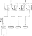
商業的なインクジェットプリント適用では、ターゲット面をプリントヘッドに何回も通すことなく、ターゲット面に大きな像を作ることができるように大きなプリント領域を有するプリント装置を提供することは有利である。これは、多数のプリントヘッドを垂直に積み重ね即ち「縫い付ける」ことによって達成される。しかしながら、垂直に積み重ねたプリントヘッドの構造は静圧の制御と関連した特別の課題を提起し、それらの商業的な利点は、これまではインク貯蔵及び供給に関するコスト又は複雑さを増すことによって限られていた。積み重ねた構造の全てのプリントヘッドに共通のリザーバから供給することは可能ではない、と言うのは均一な静圧が達成し得ないからである。図1で分かるように、リザーバの流体レベルより上に配置されたプリントヘッドは負の静圧を受けるが、リザーバより下に配置されたプリントヘッドは正の静圧を受ける。その上、図2に示すように、各プリントヘッドに別々のレベル制御式リザーバを設けることは可能であるが、そのような構成のコストはひどく高い。加えて、プリントヘッド間の空間の制限及び密な間隔はリザーバ及びレベル制御装置をこの形態で取り付けることを物理的に不可能にする。
先行技術の分配装置は、製造及び保守と関連した複雑さ及びコストのために、積み重ねたプリントヘッド構造に容易に適用できない。かくして、容易且つ安価に構成でき、積み重ねた構造の各プリントヘッドに供給されるインクの静圧の適切且つ信頼できる制御をもたらすインクジェット流体分配装置が望まれる。
本発明によれば、上下に垂直に配置された少なくとも2組のオリフィスを有する複合プリントヘッドにインクを供給するための装置であって、
オリフィスの前記組の各々のためのものであって、オリフィスに液体を流通させる液体区画室を有し、各前記区画室は、余分の液体を前記区画室からその縁を越えて流出させることによって、該区画室内の液体のレベルを所望充填高さに維持するように構成され、前記区画室は液体を区画室から次の下方の区画室に流出させるために、互いに対して位置決めされ、前記インク区画室の最も下の区画室からのインクの流出を受け、液体を区画室の最も上の区画室に供給するためのリザーバをさらに有し、各区画室の所望充填高さは、それぞれの組のオリフィスへの流入口に関してある高さにあり、それによって、流入口内の液体に作用する圧力を生じさせる静的高さの差を定める、上記装置を提供する。
本発明の好ましい実施形態では、数個のプリントヘッドが各々基材にプリントし又はマーク付けするための1組のオリフィスを有する。各プリントヘッドには多区画室リザーバの区画室の1つから別々の供給ラインを経て供給される。区画されたインクリザーバは各区画室内に所定の最適な静圧を維持する堰装置を利用する。各プリントヘッドへの供給圧力は1組のオリフィスに直ぐ近い流入口の高さに対して各区画室における流体柱の相対高さによって制御される。流体の高さはその区画室と関連した堰の高さ又はかかる堰による流体のレベルによって制御されてもよい。
本発明は他のインクジェット流体分配装置に比して顕著な利点を提供する。堰装置が個々の区画室内のインクの所望レベルを自動的に維持するので、区画室毎に個々のレベル検出器の必要がなく、それによって部品及びコストを減少させる。
今、本発明を添付図面を参照して例示として説明する。
図1は上記のごとき先行技術のプリントヘッド及びインク分配装置の図である。
図2は積み重ねたプリントヘッド構造のための独立のレベル制御装置と関連した課題を示すである。
図3は本発明の好ましい実施形態である。
図4は本発明の真空チャンバーの特徴の図である。
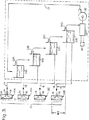
図3を参照すると、本発明を具体化する流体装置は複数のインクジェットプリントヘッド12A−12Dを含む複合プリントヘッド12を有する。複合プリントヘッド12は定置であり、複合プリントヘッドに対して移動するターゲット面(図示せず)に像を印刷するように配列される。変形例として、複合プリントヘッド12はターゲット面に対して移動できてもよいし、或いは複合プリントヘッド12とターゲット面の両方が互いに移動できてもよい。
4つの間隔を隔てたプリントヘッド12A−12Dとして概略的に示したけれども、複合プリントヘッド12は好ましくは、インクがプリントヘッドから射出されるときインクを均一に分配するように一体に取り付けられた3つ又は4つの別個の内部プリントヘッド又はマニホルドを有する、印刷すべき領域の所望幅を作るのに任意の数のプリントヘッドを使用してもよいことが理解されよう。
好ましくは、各プリントヘッド12A−12Dは一組の射出ノズル又はオリフィス14を有し、該ノズル又はオリフィスには各プリントヘッド12A−12D内の共通のチャンバー又はマニホルド16によって流体が供給される。一組のオリフィスは図示したように数が12個あるが、数はそれよりも多くても少なくてもよく、オリフィスの数及びこれらのオリフィスのパターンを選択することは当業者の範囲内である。マニホルド16には関連した流入口18及びプリントヘッド12A−12Dの取り付けられた供給ライン19を介して流体が供給される。オリフィスの各組毎に別々のプリントヘッドを有することが望ましいけれども、単一のプリントヘッドが関連した流入口をもった2組又はそれ以上の組のオリフィスを有してもよい。又、数組のオリフィスが単一列をなすように示されているけれども、一組に多列のオリフィスがあっても良いし或いは他の形態があってもよく、これらの当業者が理解できるところである。
供給ライン19からプリントヘッド12A−12Dにインクを供給するために、各プリントヘッド12A−12Dは堰22A−22Dを使用してインクの一定流体レベルを維持する関連した区画室20A−20Dを備える。各堰22は、一方の区画室から次の下の区画室にインクの流れを可能にするための、或いは、最も下の区画室20Dの場合には、リザーバ24に戻すための開口、ドレイン又は他の出口を有する。ポンプ26がリザーバ24から戻りライン27を経て最も上のリザーバ20Aにインクの低容積流れをもたらす。適切なインク保有量が主貯蔵容器からリザーバ24に確実に供給されるようにする検出装置28も設けられている。適量のインクが区画室に供給されるようにするために、戻りライン27内の流体の流量を制御する装置が設けられる。例えば、バブル又は他の制御装置を利用しても良いし、或いはインクを供給ラインから所望の一定流量で圧送するようにポンプを構成してもよい。
理解されるように、各区画室20内のインクレベルは一定に維持され、従って、関連した区画室内のインクレベルより上の供給ラインの高さHによって決定される、各プリントヘッドの流入口での静圧は各プリントヘッドについて同じである。プリントヘッド12、好ましくはプリントヘッド12毎の全体の組のオリフィスは、供給ライン19内に負圧を生じさせるように、関連した区画室20内のインクレベルより上に配置され、この負圧は供給ラインの毛管力と組合わさって、オリフィス14の直ぐ近くにある流入口18に適切な圧力を生じさせる。
ガスの蒸気圧を下げ、インク中の溶解空気を減少させるために、リザーバの上の膜又は各容器内のインクの上の部分真空のような脱ガス装置が設けられる。変形例として、容器20A−20Dのすべてを図4に示すように、単一の真空チャンバー30内においてもよい。図示したように、容器20はチャンバー30内で積み重ねられ、そしてインク中の溶解空気を減少させる低い負圧を生じさせるための単一のポート32を有する。図示したように、容器20は又、隣接した容器からの流出が反対方向であり、それによって容器を垂直配列に近づけて空間を保存するように積み重ねられる。適量の流体がリザーバ24から容器20A−20Dに供給されるよにする制御装置34が設けられる。
又、区画室20A−20D内のインクのレベルに対するプリントヘッド12A−12D、従って組のオリフィス14の高さを調整する調整機構を設けてもよい。このタイプの調整機構は当該技術で知られており、複合プリントヘッド12をユニットとして謂整するように構成されてもよい。調整機構は又プリントヘッドか互いに一体に接合されていないことを条件に、プリントヘッド12A−12Dの高さを独占に調整するように構成されてもよい。
同様に、プリントヘッド12A−12D及びそれらの関連した組のオリフィス14の高さに対する、区画室20A−20Dの高さ、かくして各区画室内のインクの高さを謂整する移動機構を設けてもよい。区画室20は千鳥配列のユニットとして互いに接合されるならば、移動機構は組立体全体の高さを調整するように構成されてもよい。変形例として、移動機構は区画室の高さを独立に調整するように構成されてもよい。この個々の調整は1996年10月10日出願の米国特許出願第08/728866号に開示された装置のような移動機構によって行われてもよい。
1つ以上の戻りラインを使用して最上の容器20Aに供給するのではなく各容器に個々に供給してもよいことは理解されよう。またバルブ、サイホン又は類似のもののような種々の他の装置を利用して各容器からのインクの排出を制御してもよい。
本発明を概略形態で示したけれども、堰を個々のカートリッジで包囲し又は単一の細長い容器の一部として包囲し、それによってインクジェットプリンターのコンパクトなインク装置を得ることは当業者の範囲内である。各堰が完全に維持されて多数のプリントヘッドに適切な静圧を確保するように、ポンプによって供給されるインクの流れ及び各プリントヘッドへの流れを監視することは本発明の範囲内である。
かくして、容易に且つ安価に構成でき、積み重なった配列の各プリントヘッドに供給されるインクの静圧の適切且つ信頼できる制御をなすインクジェット流体分配装置を提供する。The present invention generally relates to ink jet printers. In particular, the present invention relates to an apparatus for applying liquid ink to a series of drop-on-demand ink jet print orifices with appropriate static pressure.
As is well known, an ink jet printing apparatus utilizes a print head that ejects ink drops from one or more orifices onto a target surface. In impulse type drop-on-demand printing, the ejection of ink from the orifice is controlled by creating a pressure pulse in an ink chamber in the printhead. Referring to the prior art FIG. 1, a
It is important that a suitable static pressure, typically a small negative static pressure, be achieved at each inkjet orifice to avoid ink drooling. The static pressure in a print head is largely due to the static pressure at the print head inlet, because the capillary force in a given print head cancels out any changes in the pressure head in the print head orifice. Is a function of Thus, the static pressure at the inlet affects the pressure at the inkjet orifice immediately adjacent to the inlet. The optimum static pressure is determined by the physical properties of the ink, such as viscosity and surface tension, wettability and the substrate material used to construct the orifice.
Secondary, the optimum static pressure of the ink is a negative pressure of 1 to 3 inches of water. As can be seen in FIG. 1 and as known from hydraulic theory, the static pressure at the inlet is a function of the height (H) difference between the inlet and the ink level of the reservoir. In particular, the static pressure at each orifice is a function of the height difference between each orifice and the ink level in the reservoir.
In commercial ink jet printing applications, it would be advantageous to provide a printing device with a large print area so that a large image can be made on the target surface without having to pass the target surface through the print head many times. This is accomplished by stacking or “stitching” multiple printheads vertically. However, vertically stacked printhead structures present special challenges associated with static pressure control, and their commercial advantages have been limited so far by increasing the cost or complexity of ink storage and supply. It was done. It is not possible to supply all printheads in a stacked structure from a common reservoir, since a uniform static pressure cannot be achieved. As can be seen in FIG. 1, printheads located above the reservoir fluid level are subject to negative static pressure, while printheads located below the reservoir are subject to positive static pressure. Moreover, as shown in FIG. 2, although it is possible to provide a separate level-controlled reservoir in the printhead, the cost of such an arrangement is prohibitive. In addition, the space limitations and tight spacing between the printheads makes it physically impossible to mount the reservoir and level control device in this configuration.
Prior art dispensing devices are not readily applicable to stacked printhead structures due to the complexity and cost associated with manufacturing and maintenance. Thus, it is desirable to have an inkjet fluid dispensing device that can be easily and inexpensively configured and provides adequate and reliable control of the static pressure of ink supplied to each printhead in a stacked configuration.
According to the present invention, there is provided an apparatus for supplying ink to a composite printhead having at least two sets of orifices vertically arranged vertically,
For each of the sets of orifices, each having a liquid compartment through which liquid is circulated to the orifices, each compartment having an excess liquid flowing out of the compartment beyond its edge. Configured to maintain a level of liquid in the compartment at a desired fill height, wherein the compartments are positioned relative to each other to allow liquid to flow from the compartment to the next lower compartment. receiving the outflow of ink from compartments lowermost compartment, it has a reservoir for supplying liquid to the uppermost compartment of the compartment to further, desired fill height of each compartment, each set An apparatus is provided that defines a static height difference that is at a height with respect to the inlet to the orifice of the fluid, thereby creating a pressure acting on the liquid in the inlet .
In a preferred embodiment of the invention, several printheads each have a set of orifices for printing or marking on a substrate. Each print head is fed via a separate feed line from one of the compartments of the multi-compartment reservoir. The partitioned ink reservoir utilizes a weir device that maintains a predetermined optimum static pressure in each compartment. The supply pressure to each print head is controlled by the relative height of the fluid column in each compartment relative to the inlet height close to a set of orifices. The height of the fluid may be controlled by the height of the weir associated with that compartment or the level of fluid by such a weir.
The present invention provides significant advantages over other inkjet fluid dispensing devices. Since the weir device automatically maintains the desired level of ink in each compartment, there is no need for a separate level detector for each compartment, thereby reducing parts and cost.
The present invention will now be described by way of example with reference to the accompanying drawings.
FIG. 1 is a diagram of a prior art printhead and ink dispensing apparatus as described above.
FIG. 2 illustrates the challenges associated with an independent level controller for a stacked printhead structure.
FIG. 3 is a preferred embodiment of the present invention.
FIG. 4 is a diagram of the features of the vacuum chamber of the present invention.
Referring to FIG. 3, a fluidic device embodying the present invention has a
Although shown schematically as four spaced
Preferably, each
In order to supply ink from
As will be appreciated, the ink level in each compartment 20 remains constant, and therefore at each printhead inlet determined by the supply line height H above the ink level in the associated compartment. The static pressure is the same for each print head. The entire set of orifices for each
In order to reduce the vapor pressure of the gas and reduce dissolved air in the ink, a degassing device such as a membrane above the reservoir or a partial vacuum above the ink in each container is provided. Alternatively, all of the
Also, an adjustment mechanism may be provided to adjust the height of the print heads 12A-12D and thus the set of
Similarly, a moving mechanism may be provided that adjusts the height of the
It will be appreciated that one or more return lines may be used to supply each container individually rather than supplying the
Although the invention has been shown in schematic form, it is within the purview of those skilled in the art to enclose the weir with individual cartridges or as part of a single elongated container, thereby obtaining a compact ink device for an ink jet printer. is there. It is within the scope of the present invention to monitor the flow of ink supplied by the pump and the flow to each printhead so that each weir is fully maintained to ensure adequate static pressure for multiple printheads. .
Thus, there is provided an inkjet fluid dispensing apparatus that can be easily and inexpensively configured and that provides adequate and reliable control of the static pressure of ink supplied to each printhead in a stacked array.
Claims (12)
オリフィス(14)の前記組の各々のためのものであって、オリフィスに液体を流通させる液体区画室(20A−20D)を有し、各前記区画室は、余分の液体を前記区画室からその縁を越えて流出させることによって、該区画室内の液体のレベルを所望充填高さに維持するように構成され、前記区画室(20A−D)は液体を区画室から次の下方の区画室に流出させるために、互いに対して位置決めされ、前記インク区画室の最も下の区画室からのインクの流出を受け、液体を区画室の最も上の区画室に供給するためのリザーバ(24)をさらに有し、各区画室(20A−D)の所望充填高さはそれぞれの組のオリフィスへの流入口(18)に関してある高さにあり、それによって、流入口(18)内の液体に作用する圧力を生じさせる静的高さの差を定め、各区画室(20A−D)について定められた静的高さの差は同じであり、且つ区画室(20A−D)は同じ容積の液体を入れるように構成され、それにより、各組のオリフィス(14)への流入口(18)内の液体に作用する負圧は同じである、上記装置。An apparatus for supplying ink to a composite printhead (12) having at least two sets of orifices (14) arranged vertically above and below,
For each of the sets of orifices (14), having liquid compartments (20A-20D) for fluid to flow through the orifices, each compartment having excess liquid from the compartments; By flowing out of the edge, the liquid level in the compartment is configured to maintain a desired fill height, the compartment (20A-D) being liquid from the compartment to the next lower compartment. A reservoir (24) positioned relative to each other for receiving the ink flow from the lowermost compartment of the ink compartment and supplying liquid to the uppermost compartment of the compartment; And the desired fill height of each compartment (20A-D) is at a certain height with respect to the inlet (18) to the respective set of orifices, thereby pressure acting on the liquid in the inlet (18) Cause static Determines the difference in height, the difference in static height defined for each compartment (20A-D) are the same, and the compartments (20A-D) is configured to contain the liquid in the same volume, it Thus, the negative pressure acting on the liquid in the inlet (18) to each set of orifices (14) is the same .
Applications Claiming Priority (5)
| Application Number | Priority Date | Filing Date | Title |
|---|---|---|---|
| US1810996P | 1996-05-22 | 1996-05-22 | |
| US60/018,109 | 1996-05-22 | ||
| US08/854,487 US6196668B1 (en) | 1997-05-12 | 1997-05-12 | Ink jet print head modules with common ink supply |
| US08/854,487 | 1997-05-12 | ||
| PCT/GB1997/001405 WO1997044194A1 (en) | 1996-05-22 | 1997-05-22 | Ink jet print head modules with common ink supply |
Publications (3)
| Publication Number | Publication Date |
|---|---|
| JP2000510780A JP2000510780A (en) | 2000-08-22 |
| JP3909443B2 true JP3909443B2 (en) | 2007-04-25 |
| JP3909443B6 JP3909443B6 (en) | 2007-08-08 |
Family
ID=
Also Published As
| Publication number | Publication date |
|---|---|
| CA2255019A1 (en) | 1997-11-27 |
| DE69708086T2 (en) | 2002-06-20 |
| JP2000510780A (en) | 2000-08-22 |
| EP0902743A1 (en) | 1999-03-24 |
| WO1997044194A1 (en) | 1997-11-27 |
| DE69708086D1 (en) | 2001-12-13 |
| EP0902743B1 (en) | 2001-11-07 |
| ATE208278T1 (en) | 2001-11-15 |
| AU2909697A (en) | 1997-12-09 |
Similar Documents
| Publication | Publication Date | Title |
|---|---|---|
| US6196668B1 (en) | Ink jet print head modules with common ink supply | |
| KR100938475B1 (en) | Droplet Deposition Apparatus | |
| CN109572226B (en) | Liquid ejection head and liquid ejection apparatus | |
| JP3419220B2 (en) | Ink jet recording device | |
| RU2506166C2 (en) | Inkjet printing device | |
| US10766272B2 (en) | Fluid ejection device | |
| US20200079085A1 (en) | Fluid ejection device | |
| US8246153B2 (en) | Bubble control unit, liquid ejecting head, and liquid ejecting apparatus | |
| US11065873B2 (en) | Liquid ejection apparatus | |
| JP4625475B2 (en) | Line-type liquid ejecting head and liquid ejecting apparatus including the same | |
| KR20080057165A (en) | Ink jet recording method | |
| CN107618264B (en) | Liquid ejecting method, liquid ejecting apparatus, and liquid ejecting head | |
| EP0902743B1 (en) | Ink jet print head modules with common ink supply | |
| JP6719920B2 (en) | Liquid ejection head and liquid ejection device | |
| JPWO2018225333A1 (en) | Ink jet head and ink jet recording apparatus | |
| JP3909443B6 (en) | Inkjet printhead module having a common ink supply | |
| JPH04358844A (en) | Ink jet recorder | |
| JPH05261934A (en) | Ink jet printer | |
| US10737501B2 (en) | Liquid discharge apparatus and driving method of liquid discharge apparatus | |
| JP2017144704A (en) | Liquid ejection substrate, liquid ejection head, and liquid ejection apparatus | |
| JP2020049872A (en) | Liquid jet head, liquid jet device, control method for liquid jet head, and control method for liquid jet device | |
| US11084284B2 (en) | Liquid ejection head | |
| JP2008049533A (en) | Inkjet recording head | |
| JP2017077638A (en) | Liquid discharge member and image formation device | |
| JPH04348948A (en) | Ink droplet jet device |
Legal Events
| Date | Code | Title | Description |
|---|---|---|---|
| A621 | Written request for application examination |
Free format text: JAPANESE INTERMEDIATE CODE: A621 Effective date: 20040212 |
|
| A131 | Notification of reasons for refusal |
Free format text: JAPANESE INTERMEDIATE CODE: A131 Effective date: 20040511 |
|
| A521 | Request for written amendment filed |
Free format text: JAPANESE INTERMEDIATE CODE: A523 Effective date: 20040810 |
|
| A131 | Notification of reasons for refusal |
Free format text: JAPANESE INTERMEDIATE CODE: A131 Effective date: 20050329 |
|
| A601 | Written request for extension of time |
Free format text: JAPANESE INTERMEDIATE CODE: A601 Effective date: 20050629 |
|
| A602 | Written permission of extension of time |
Free format text: JAPANESE INTERMEDIATE CODE: A602 Effective date: 20050815 |
|
| A521 | Request for written amendment filed |
Free format text: JAPANESE INTERMEDIATE CODE: A523 Effective date: 20050929 |
|
| A131 | Notification of reasons for refusal |
Free format text: JAPANESE INTERMEDIATE CODE: A131 Effective date: 20060418 |
|
| A601 | Written request for extension of time |
Free format text: JAPANESE INTERMEDIATE CODE: A601 Effective date: 20060718 |
|
| A602 | Written permission of extension of time |
Free format text: JAPANESE INTERMEDIATE CODE: A602 Effective date: 20060904 |
|
| A521 | Request for written amendment filed |
Free format text: JAPANESE INTERMEDIATE CODE: A523 Effective date: 20061018 |
|
| A72 | Notification of change in name of applicant |
Free format text: JAPANESE INTERMEDIATE CODE: A721 Effective date: 20061109 |
|
| TRDD | Decision of grant or rejection written | ||
| A01 | Written decision to grant a patent or to grant a registration (utility model) |
Free format text: JAPANESE INTERMEDIATE CODE: A01 Effective date: 20061212 |
|
| A61 | First payment of annual fees (during grant procedure) |
Free format text: JAPANESE INTERMEDIATE CODE: A61 Effective date: 20070111 |
|
| R150 | Certificate of patent or registration of utility model |
Free format text: JAPANESE INTERMEDIATE CODE: R150 |
|
| LAPS | Cancellation because of no payment of annual fees |