JP3908570B2 - Air conditioner - Google Patents
Air conditioner Download PDFInfo
- Publication number
- JP3908570B2 JP3908570B2 JP2002065964A JP2002065964A JP3908570B2 JP 3908570 B2 JP3908570 B2 JP 3908570B2 JP 2002065964 A JP2002065964 A JP 2002065964A JP 2002065964 A JP2002065964 A JP 2002065964A JP 3908570 B2 JP3908570 B2 JP 3908570B2
- Authority
- JP
- Japan
- Prior art keywords
- fan
- drain pan
- bell mouth
- air conditioner
- opening
- Prior art date
- Legal status (The legal status is an assumption and is not a legal conclusion. Google has not performed a legal analysis and makes no representation as to the accuracy of the status listed.)
- Expired - Lifetime
Links
Images


Landscapes
- Devices For Blowing Cold Air, Devices For Blowing Warm Air, And Means For Preventing Water Condensation In Air Conditioning Units (AREA)
- Air Filters, Heat-Exchange Apparatuses, And Housings Of Air-Conditioning Units (AREA)
Description
【0001】
【発明の属する技術分野】
この発明は、空気調和装置、特にベルマウスを有する空気調和装置に関するものである。
【0002】
【従来の技術】
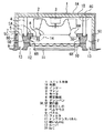
図9は、従来の例えば天井設置形の空気調和装置の概略構成を示す断面図である。この図において、1は装置の箱体を構成するユニット本体で、下方から見た形状がほぼ四角形に形成されている。2は吸い込み形のファンで、ユニット本体内の中央部に装着されたモータ3によって駆動され、前面から空気を吸い込むと共に、側面に吹き出すようにされている。4はファン2の側面に配設された熱交換器で、ファン2を囲むようにユニット本体1の内側に設けられている。
5はドレンパンで、熱交換器4の下部に配設され、ファン2に対向する部分にファンの外径より大きい辺の四角状の開口部6を有すると共に、ユニット本体の外周部1Aとの間に熱交換器4を経た空気の吹き出し口7を形成している。
【0003】
8は板金製のベルマウスで、構成及び固定方法については後述する。9はユニット本体1の下端に設けられ、ドレンパン5及びベルマウス8をカバーするパネル、10はパネル9の中央部に、ベルマウス8に対応して装着されたフィルタ、11はフィルタ10の外方でパネル9に装着されたメンテナンスパネル、12は吸い込み口、13は吹き出し口7のルーバである。
図10は、図9において円14で囲んだ部分を拡大して示す概略構成図である。この図において、板金製のベルマウス8は、ドレンパン5の四角状の開口部6に対応した外形を有する基体部8Aと、この基体部8Aからファン側に折曲され、ファン2に対応した位置で円形の吸い込み口15を形成する周壁部8Bとから構成されている。また、ベルマウスの基体部8Aの端部は、四角状の各辺に風漏れ防止用のシール材16を介して4本のねじ17によってドレンパン5に固定されている。ベルマウス8は板金製であるため、周壁部8Bは容易に形成することができ、周壁部8Bの先端部8Cは内径を拡大するように外側に向けて折曲され、ファン2の吸い込み圧力損を低減するようにしている。
【0004】
図11は、図9において、円14で囲んだ部分の構成の他の例を拡大して示す概略図である。この例では、ベルマウス8は樹脂製であり、周壁部8Bの先端部8Cを図10に示す板金製の場合と同様に、外側に向けて折曲させようとすれば、樹脂成形時にスライド型が必要となり、金型費が増大するため、外側に向けた折曲構造とはせず、基体部8Aの延長方向に対して垂直または吸い込み口15側に僅かに傾斜した構成とし、樹脂成形時の型抜きが容易となるようにしている。
【0005】
【発明が解決しようとする課題】
従来の空気調和装置は以上のように構成されており、図10に示すように、ベルマウス8を板金製としてベルマウス部の圧力損失を低減する構成とした場合には、樹脂製に比べてコストが増大するという問題点があった。
逆に、コスト低減のために図11に示すように、ベルマウス8を樹脂製とした場合には、型抜きを容易にする観点から周壁部8Bの先端部8Cを外側に折曲して内径を拡大できないため、ベルマウス部の圧力損失が板金製に比べて増大するという問題点があった。また、ベルマウス部の風漏れに対するシール性を向上させるために、ドレンパン5とベルマウス8との間にシール材16を設けると共に、固定用のねじ17が必要になるという問題点があった。
この発明は、上記のような問題点を解消するためになされたもので、ベルマウスを樹脂製にしてコスト低減を図ると共に、ベルマウス部の圧力損失も改善することができる空気調和装置を提供することを目的とする。
【0006】
【課題を解決するための手段】
この発明に係る空気調和装置は、箱体を構成するユニット本体内に装着され、前面から空気を吸い込むと共に側面に吹き出すファンと、上記ファンの前面に配設されたベルマウスと、上記ファンの側面に配設された熱交換器とを備えた空気調和装置において、上記ベルマウスは、樹脂によって形成され、吸い込み口を有する基体部と、この基体部と一体成形され上記吸い込み口の周縁から上記基体部に対してほぼ垂直方向に上記ファン側に延在する周壁部とから構成され、上記周壁部の先端部に上記ファンに近づくに従って上記周壁部の内径が次第に大きくなるような傾斜面を形成したものである。
【0007】
この発明に係る空気調和装置は、また、上記傾斜面は上記ベルマウスの周壁部の外側面との接合部が周壁部の内側面との接合部よりファン側に位置するように形成されたものである。
【0008】
この発明に係る空気調和装置は、また、箱体を構成するユニット本体内に装着され、前面から空気を吸い込むと共に側面に吹き出すファンと、上記ファンの側面に配設された熱交換器と、この熱交換器に装着され、上記ファンの前面で上記ファンの外径より大きい開口部を有するドレンパンと、上記ドレンパンの開口部に装着されたベルマウスとを備えた空気調和装置において、上記ベルマウスは、樹脂によって形成され、吸い込み口を有する基体部と、この基体部と一体成形され上記吸い込み口の周縁から上記ファン側に延在する周壁部と、上記基体部のファン側表面に設けられ上記ドレンパンの開口部の内周面に当接する凸部とを有するものである。
【0009】
この発明に係る空気調和装置は、また、上記ベルマウスの凸部を、断面が三角形状に形成するものである。
【0010】
この発明に係る空気調和装置は、また、上記ドレンパンの開口部の上記ベルマウス側の内周面角部を傾斜面にしたものである。
【0011】
この発明に係る空気調和装置は、また、上記ドレンパンが、上記開口部を有する本体部と、この本体部の反熱交換器側で上記開口部より大径の他の開口部を形成するベルマウス取付部とから構成され、上記ベルマウスが、樹脂によって形成され、吸い込み口を有すると共に上記ドレンパンのベルマウス取付部と係合し得るようにされた基体部と、この基体部と一体成形され上記吸い込み口の周縁から上記ファン側に延在する周壁部と、上記基体部の端部から反ファン側に延在する固定部と、この固定部のドレンパン側に設けられた突出部とから構成されるものである。
【0012】
この発明に係る空気調和装置は、また、上記ドレンパンが、上記開口部を有する本体部と、この本体部の反熱交換器側で上記開口部より大径の他の開口部を形成するベルマウス取付部とから構成され、上記ベルマウスが、樹脂によって形成され、吸い込み口を有すると共に上記ドレンパンのベルマウス取付部と係合し得るようにされた基体部と、この基体部と一体成形され上記吸い込み口の周縁から上記ファン側に延在する周壁部と、上記基体部のファン側表面に設けられ上記ドレンパンの開口部の内周面に当接する凸部と、上記基体部の端部から反ファン側に延在する固定部と、この固定部のドレンパン側に設けられた突出部とから構成されるものである。
【0013】
この発明に係る空気調和装置は、また、上記ベルマウスの固定部に設けられる突出部を、ベルマウスの基体部側に向けてなだらかに低下していく形状としたものである。
【0014】
この発明に係る空気調和装置は、また、上記ユニット本体を板金製の外郭と、その内側に重ねて設けられる発泡スチロール製のインナーとで構成すると共に、上記ドレンパンに上記インナーの端面と当接する当接部を設け、上記インナーとドレンパンの当接部との当接面を、上記ドレンパンからインナー側への押圧力の作用時に上記インナーに対して上記外郭と接する方向に力が作用するような斜面としたものである。
【0015】
【発明の実施の形態】
実施の形態1.
以下、この発明の実施の形態1を図にもとづいて説明する。図1は、実施の形態1の概略構成を示す断面図である。この図において、1は装置の箱体を構成するユニット本体で、板金製の外郭1Aと、その内側に重ねて設けられる発泡スチロール製のインナー1Bとで構成され、下方から見た形状がほぼ四角形に形成されている。2は吸い込み形のファンで、ユニット本体1内の中央部に装着されたモータ3によって駆動され、前面から空気を吸い込むと共に、側面に吹き出すようにされている。4はファン2の側面に配設され、U字状に形成された熱交換器で、図2に示すように、2つの直線部4Aとファン2との距離及び湾曲部4Bとファン2との距離が等しくなるように、ファン2を囲むような形でユニット本体1内に設けられている。なお、図1に円4Cで示す熱交換器4とインナー1Bとの当接部は、図3に示すように、インナー1Bの熱交換器4との対向部に突起1Cを熱交換器4の積長に合わせて、また、列ピッチの間隔で数列分、形成し熱交換器4の上面を突起1Cがややつぶれ気味となるまで突起1Cに押し当てて両者間の隙間がなくなるようにしている。
【0016】
5はドレンパンで、熱交換器4の下部に配設され、ファン2に対向する部分にファン2の外径より大きい辺の四角状の開口部6Aを有する本体部5Aと、この本体部の反熱交換器側に位置して上記開口部6Aより大径の他の開口部6Bを形成するベルマウス取付部5Bと、このベルマウス取付部との間に熱交換器4を経た空気の吹き出し口7を形成すると共に、ユニット本体1のインナー1Bの端面と当接する傾斜端面5Cを有する周縁部5Dとから構成されている。なお、傾斜端面5Cはドレンパンのユニット本体1への挿入時に、周縁部5Dをインナー1B側へ押圧してインナー1Bに押圧力を作用させた時、インナー1Bに対して外郭1Aと接する方向に力が作用するように図示のような傾斜面とされている。
8は樹脂成形されたベルマウスで、構成及び固定方法については後述する。
【0017】
9はユニット本体1の下端に設けられ、ドレンパン5及びベルマウス8をカバーするパネル、10はパネル9の中央部に、ベルマウス8に対応して装着されたフィルタ、11はフィルタ10の下方でパネル9に装着されたメンテナンスパネルで、フィルタ10やファン2、モータ3のメンテナンス時に容易に取り外しできる構成とされている。12は室内の空気を吸い込む吸い込み口、13は吹き出し口7のルーバである。また、図2において、20は熱交換器4に結合され、熱交換用の媒体を外部から供給するための配管、21はドレンパン5に溜まったドレン水を機外へ排出するためのドレンポンプセットで、図4に示すように、インナー1Bと一体に成形された発泡スチロール製のインナー1Dにインサートされた板金(図示せず)に固定されたドレンポンプ22とドレンポンプカバー23とから構成され、ユニット本体1の外郭1Aから電気的に絶縁された状態でドレンポンプ22の吸い込み口がドレンパン5のドレン水中に位置するように設けられている。
【0018】
ドレンポンプカバー23は、ドレンポンプ22が異常により高温または万一発火した場合でも、近辺のインナー1Bやドレンパン5に延焼するのを防ぐためのものである。また、ドレンポンプセット21は発泡スチロール製のインナー1D及び1Bを介してユニット本体1の外郭1Aに結合されているため、ドレンポンプ22の振動は両インナー1D及び1Bによって吸収されることになる。
なお、図2の24はメンテナンス用カバーで、ドレンパン5を取り外すことなく、ドレンポンプセット21や配管20のメンテナンスが出来るようにするために設けられたものである。即ち、これらのメンテナンス時には、ユニット本体1の下面からメンテナンスパネル11とフィルタ10を取り外し、更にベルマウス8及びファン2を取り外すことにより、メンテナンス用カバー24を取り外すことができる。
【0019】
図5は、樹脂成形されたベルマウス8の構成を示すもので、(a)は斜視図、(b)は平面図、(c)は(b)のA−A線における断面図である。
これらの図において、8Aは吸い込み口15を有する基体部、8Bは吸い込み口15の周縁から基体部8Aに対してほぼ垂直方向、即ち、ユニット本体1への取付状態においてファン2側に延在する周壁部で、その先端部8Cは先端に向けて、即ちユニット本体1への取付状態においてはファン2に近づくに従って厚さを薄くし、その内径が次第に大きくなるような傾斜面8Dとされている。
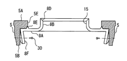
また、8Eは基体部8Aのファン2側表面に設けられた凸部で、図1に円14で囲んだ部分の拡大構成図を図6に示すように、断面が三角形状に形成され、その斜面をドレンパン5の開口部6の内周面5Eに当接させることにより、ベルマウス8の位置決めを容易にしている。
【0020】
また、ドレンパン5の開口部6の内周面5Eは、ベルマウス側の角部5Fを図7に示すように、ベルマウスの凸部8Eの斜面に対応した傾斜面にして、三角形状の凸部8Eとの係合を容易にすることにより、ベルマウスの位置決めを更に容易、確実にしている。8Fは基体部8Aのうち対向する2辺の端部から周壁部8Bの延在方向とは逆方向、即ちユニット本体1への取付状態において反ファン側に延在する板状の固定部、8Gは固定部8Fの外面、即ちベルマウス8の取付時にドレンパン5側となる面に設けられた突出部で、図5(c)、図6等に示されるように、基体部8A側に向けてなだらかに低下していく形状とされている。
図7に示すように、対向する2つの固定部8Fの各突出部8Gの頂点間の寸法L2とドレンパンのベルマウス取付部5Bの開口部6Bの寸法L1との関係は、L2=L1+αとなっており、2つの突出部8Gの合計突出寸法がαに相当する。
【0021】
従って、図7に矢印Xで示すように、ベルマウス8をドレンパン5のベルマウス取付部5Bに挿入すると、突出部8Gがドレンパン5のベルマウス取付部5Bと係合し、その係合位置が挿入の進行につれてなだらかに高くなるため、ベルマウスの固定部8Fには図7に矢印Yで示すように、内側に曲げる力が作用し、その結果、図7に矢印Zで示すように、ベルマウス8の底部を図において上方に押し上げる力が作用し、三角形状の凸部8Eがドレンパン5の開口部6Aの内周面5E側に変位するため図6及び図8に示すように、ドレンパンの内周面5Eとベルマウスの凸部8Eとが密着性を増す。この状態で固定部8Fは、図8に示すように、ねじ30によってドレンパンのベルマウス取付部5Bに固定されるが、上述した曲げ力の作用によってねじ止めされていない個所でもドレンパンに対する密着性が高いため、ねじ止め個所を2個所に抑えることができる。
【0022】
このような構成において、モータ3に給電すると、ファン2が回転駆動されるため、吸い込み口12から室内の空気が吸い込まれ、フィルタ10を通過してベルマウス8により滑らかに縮流されてファン2に吸い込まれる。
吸い込まれた空気は、熱交換器4に向けて吹き出され、熱交換器4で熱交換された後、吹き出し口7から室内に向けて吹き出される。ファン2に吸い込まれる空気はベルマウス8の周壁部8Bの表面に沿う流れとなり、ベルマウス8の形状により吸い込み空気の圧力損失が変化する。特に、急拡大、急縮小は圧力損失が大きいが、この実施の形態では、樹脂成形時に周壁部8Bの板厚を大きめに設定し、その先端部8Cを、ファン2に近づくに従って内径が次第に大きくなるような傾斜面8Dとしているため、樹脂成形時にスライド型を使用することなく、圧力損失を小さく抑えることが出来る。
【0023】
また、この実施の形態では図1に示すように、ユニット本体1が板金製の外郭1Aと発泡スチロール製のインナー1Bとで構成され、インナー1Bは板金よりもたわみやすいため、外郭1Aとインナー1Bとの間に隙間が生じる場合がある。しかし、インナー1Bの端面とドレンパンの周縁部5Dとの当接面を図1に示すような斜面5Cとしているため、ドレンパン5をユニット本体1に挿入する際、図1において上向きの力が斜面5Cで上向きの力と外向きの横方向の力とに分けられ、横方向の力によってインナー1Bが外郭1Aに押圧されるため、インナー1Bと外郭1Aとを密着させることができる。
【0024】
【発明の効果】
この発明に係る空気調和装置は、箱体を構成するユニット本体内に装着され、前面から空気を吸い込むと共に側面に吹き出すファンと、上記ファンの前面に配設されたベルマウスと、上記ファンの側面に配設された熱交換器とを備えた空気調和装置において、上記ベルマウスは、樹脂によって形成され、吸込口を有する基体部と、この基体部と一体成形され上記吸込口の周縁から上記ファン側に延在する周壁部とから構成され、上記周壁部の先端部が上記ファンに近づくに従ってその内径が次第に大きくなるような形状とされているため、ベルマウスの製造が容易となりコストを低減することができ、かつ吸い込み圧力損失を小さく抑えることができる。
【0025】
この発明に係る空気調和装置は、また、箱体を構成するユニット本体内に装着され、前面から空気を吸い込むと共に側面に吹き出すファンと、上記ファンの側面に配設された熱交換器と、この熱交換器に装着され、上記ファンの前面で上記ファンの外径より大きい開口部を有するドレンパンと、上記ドレンパンの開口部に装着されたベルマウスとを備えた空気調和装置において、上記ベルマウスは、樹脂によって形成され、吸込口を有する基体部と、この基体部と一体成形され上記吸込口の周縁から上記ファン側に延在する周壁部と、上記基体部のファン側表面に設けられ上記ドレンパンの開口部の内周面に当接する凸部とを有するものであるため、ベルマウスの位置決めが容易となる他、シール材を使用することなくベルマウスを固定することができる。
【0026】
この発明に係る空気調和装置は、また、上記ドレンパンの開口部の上記ベルマウス側の内周面角部を傾斜面にしたものであるため、ドレンパンとベルマウスとの密着性を更に向上させることができる。
【0027】
この発明に係る空気調和装置は、また、上記ドレンパンが、上記開口部を有する本体部と、この本体部の反熱交換器側で上記開口部より大径の他の開口部を形成するベルマウス取付部とから構成され、上記ベルマウスが、樹脂によって形成され、吸込口を有すると共に上記ドレンパンのベルマウス取付部と係合し得るようにされた基体部と、この基体部と一体成形され上記吸込口の周縁から上記ファン側に延在する周壁部と、上記基体部の端部から反ファン側に延在する固定部と、この固定部のドレンパン側に設けられた突出部とから構成されるものであるため、ベルマウスの装着時にベルマウスの中央部がファン側に凸となるように変形する結果、ベルマウスの固定個所以外の部分もドレンパンに密着し、シール性を上げることができる。このため、ねじ止め等の固定個所を削減することができる。
【0028】
この発明に係る空気調和装置は、また、上記ユニット本体を板金製の外郭と、その内側に重ねて設けられる発泡スチロール製のインナーとで構成すると共に、上記ドレンパンに上記インナーの端面と当接する当接部を設け、上記インナーとドレンパンの当接部との当接面を、上記ドレンパンからインナー側への押圧力の作用時に上記インナーに対して上記外郭と接する方向に力が作用するような斜面としたため、ドレンパンのユニット本体への挿入装着時にドレンパンとインナーとが当接する斜面において、ドレンパンの挿入方向の力と外向きの力とに分かれ、外向きの力によってインナーが外郭に押圧される結果、インナーと外郭とを密着させることができる。
【図面の簡単な説明】
【図1】 この発明の実施の形態1の概略構成を示す断面図である。
【図2】 実施の形態1における内部構成を下面から見た状態を示す概略図である。
【図3】 実施の形態1における熱交換器とユニット本体内面との関係を示す部分拡大図である。
【図4】 実施の形態1におけるドレンポンプセットの取付状態を示す内部構成図である。
【図5】 実施の形態1におけるベルマウスの構成を示すもので、(a)は斜視図、(b)は平面図、(c)は(b)のA−A線における断面図である。
【図6】 図1において円14で囲んだ部分を拡大して示す概略構成図である。
【図7】 実施の形態1におけるベルマウスの取付時の状況を説明するための説明図である。
【図8】 実施の形態1におけるベルマウスの取付状態を示す概略図である。
【図9】 従来の空気調和装置の概略構成を示す断面図である。
【図10】 図9において円14で囲んだ部分を拡大して示す概略構成図である。
【図11】 図9において円14で囲んだ部分の他の構成の例を拡大して示す概略構成図である。
【符号の説明】
1 ユニット本体、 1A 外郭、 1B,1D インナー、 2 ファン、3 モータ、 4 熱交換器、 5 ドレンパン、 6A,6B 開口部、 7 吹き出し口、 8 ベルマウス、 8A 基体部、 8B 周壁部、 8C先端部、 8D 傾斜面、 8E 凸部、 8F 固定部、 8G 突出部、9 パネル、 10 フィルタ、 11 メンテナンスパネル、 12,15吸い込み口、 20 配管、 21 ドレンポンプセット、 22 ドレンポンプ、 23 ドレンポンプカバー、 24 メンテナンス用カバー、 30 ねじ。[0001]
BACKGROUND OF THE INVENTION
The present invention relates to an air conditioner, and more particularly to an air conditioner having a bell mouth.
[0002]
[Prior art]
FIG. 9 is a cross-sectional view showing a schematic configuration of a conventional, for example, ceiling-mounted air conditioner. In this figure, reference numeral 1 denotes a unit main body constituting the box of the apparatus, and the shape viewed from below is formed in a substantially square shape.
A
[0003]
FIG. 10 is a schematic configuration diagram illustrating an enlarged portion surrounded by a
[0004]
FIG. 11 is an enlarged schematic diagram showing another example of the configuration of the portion surrounded by the
[0005]
[Problems to be solved by the invention]
The conventional air conditioner is configured as described above. As shown in FIG. 10, when the
Conversely, as shown in FIG. 11 in order to reduce the cost, when the
The present invention has been made to solve the above problems, and provides an air conditioner that can reduce the cost by making the bell mouth made of resin and can also improve the pressure loss of the bell mouth portion. The purpose is to do.
[0006]
[Means for Solving the Problems]
An air conditioner according to the present invention is mounted in a unit main body constituting a box body, sucks air from the front and blows out to the side, a bell mouth disposed on the front of the fan, and a side of the fan in the air conditioning apparatus and a disposed heat exchanger, the bell mouth is formed by a resin, and a base portion having a suction port, said substrate from the peripheral edge of the base part and is integrally formed above the suction port It is composed of a peripheral wall portion extending in the fan side in a substantially vertical direction with respect to the parts, to form an inclined surface such as the inner diameter of the peripheral wall portion is gradually increased toward the above fan tip end portion of the peripheral wall Is.
[0007]
In the air conditioner according to the present invention, the inclined surface is formed such that a joint portion with the outer side surface of the peripheral wall portion of the bell mouth is located closer to the fan side than a joint portion with the inner side surface of the peripheral wall portion. It is.
[0008]
An air conditioner according to the present invention is also mounted in a unit main body constituting a box, sucks air from the front and blows it to the side, a heat exchanger disposed on the side of the fan, In an air conditioner equipped with a drain pan attached to a heat exchanger and having an opening larger than an outer diameter of the fan on the front surface of the fan, and a bell mouth attached to the opening of the drain pan, the bell mouth is A base portion formed of resin and having a suction port; a peripheral wall portion integrally formed with the base portion and extending from the periphery of the suction port toward the fan side; and the drain pan provided on the fan side surface of the base portion And a convex portion that comes into contact with the inner peripheral surface of the opening.
[0009]
In the air conditioner according to the present invention, the convex portion of the bell mouth is formed to have a triangular cross section.
[0010]
In the air conditioner according to the present invention, the inner peripheral surface corner on the bell mouth side of the opening of the drain pan is inclined.
[0011]
The air conditioner according to the present invention is also a bell mouth in which the drain pan forms a main body having the opening and another opening having a larger diameter than the opening on the side of the counter heat exchanger of the main body. A base portion that is formed of resin, has a suction port, and can be engaged with the bell mouth mounting portion of the drain pan, and is integrally molded with the base portion. It consists of a peripheral wall portion extending from the peripheral edge of the suction port to the fan side, a fixing portion extending from the end portion of the base portion to the anti-fan side, and a protruding portion provided on the drain pan side of the fixing portion. Is.
[0012]
The air conditioner according to the present invention is also a bell mouth in which the drain pan forms a main body having the opening and another opening having a larger diameter than the opening on the side of the counter heat exchanger of the main body. A base portion that is formed of resin, has a suction port, and can be engaged with the bell mouth mounting portion of the drain pan, and is integrally molded with the base portion. A peripheral wall portion extending from the peripheral edge of the suction port to the fan side, a convex portion provided on the fan side surface of the base portion and abutting on the inner peripheral surface of the opening of the drain pan, and opposite from the end portion of the base portion The fixing portion extends to the fan side and a protrusion provided on the drain pan side of the fixing portion.
[0013]
In the air conditioner according to the present invention, the protruding portion provided on the fixed portion of the bell mouth is gradually lowered toward the base portion of the bell mouth.
[0014]
In the air conditioner according to the present invention, the unit main body is configured by a sheet metal outer shell and a foamed polystyrene inner layer provided on the inner side of the unit main body, and the drain pan is in contact with the inner end surface of the inner wall. Provided with a slope, and a contact surface between the inner portion and the contact portion of the drain pan is such that a force acts in a direction in which the inner surface is in contact with the outer shell when the pressing force is applied from the drain pan to the inner side. It is a thing.
[0015]
DETAILED DESCRIPTION OF THE INVENTION
Embodiment 1 FIG.
Embodiment 1 of the present invention will be described below with reference to the drawings. FIG. 1 is a cross-sectional view showing a schematic configuration of the first embodiment. In this figure, reference numeral 1 denotes a unit main body constituting the box of the apparatus, which is composed of a sheet metal
[0016]
A
[0017]
A
[0018]
The
Note that
[0019]
FIGS. 5A and 5B show the configuration of the resin-molded
In these drawings,
Further, 8E is a convex portion provided on the surface of the
[0020]
Further, the inner
As shown in FIG. 7, the relationship between the dimension L2 between the vertices of the protruding
[0021]
Therefore, as shown by an arrow X in FIG. 7, when the
[0022]
In such a configuration, when power is supplied to the motor 3, the
The sucked air is blown out toward the
[0023]
Further, in this embodiment, as shown in FIG. 1, the unit main body 1 is composed of a sheet metal
[0024]
【The invention's effect】
An air conditioner according to the present invention is mounted in a unit main body constituting a box body, sucks air from the front and blows out to the side, a bell mouth disposed on the front of the fan, and a side of the fan The bell mouth is formed of resin and has a base portion having a suction port, and the fan is integrally formed with the base portion from the periphery of the suction port. Since the inner wall gradually increases in size as the tip of the peripheral wall approaches the fan, the bell mouth is easily manufactured and the cost is reduced. And the suction pressure loss can be kept small.
[0025]
An air conditioner according to the present invention is also mounted in a unit main body constituting a box, sucks air from the front and blows it to the side, a heat exchanger disposed on the side of the fan, In an air conditioner equipped with a drain pan attached to a heat exchanger and having an opening larger than an outer diameter of the fan on the front surface of the fan, and a bell mouth attached to the opening of the drain pan, the bell mouth is A base portion formed of resin and having a suction port; a peripheral wall portion integrally formed with the base portion and extending from the periphery of the suction port to the fan side; and the drain pan provided on the fan side surface of the base portion In addition to facilitating positioning of the bell mouth, the bell mouth can be fixed without using a sealing material. Door can be.
[0026]
In the air conditioner according to the present invention, the inner peripheral surface corner on the bell mouth side of the opening of the drain pan is an inclined surface, so that the adhesion between the drain pan and the bell mouth is further improved. Can do.
[0027]
The air conditioner according to the present invention is also a bell mouth in which the drain pan forms a main body having the opening and another opening having a larger diameter than the opening on the side of the counter heat exchanger of the main body. A base portion made of resin, having a suction port and capable of engaging with the bell mouth mounting portion of the drain pan, and integrally formed with the base portion. It consists of a peripheral wall portion extending from the peripheral edge of the suction port to the fan side, a fixing portion extending from the end portion of the base portion to the non-fan side, and a protruding portion provided on the drain pan side of the fixing portion. As a result, when the bell mouth is mounted, the bell mouth is deformed so that the center of the bell mouth protrudes toward the fan. As a result, the portions other than the fixed portion of the bell mouth are also closely attached to the drain pan, and the sealing performance can be improved. . For this reason, fixing parts, such as screwing, can be reduced.
[0028]
In the air conditioner according to the present invention, the unit main body is configured by a sheet metal outer shell and a foamed polystyrene inner layer provided on the inner side of the unit main body, and the drain pan is in contact with the inner end surface of the inner wall. Provided with a slope, and a contact surface between the inner portion and the contact portion of the drain pan is such that a force acts in a direction in which the inner surface is in contact with the outer shell when the pressing force is applied from the drain pan to the inner side. Therefore, when the drain pan is inserted into the unit body, the drain pan and the inner surface are in contact with each other, and the drain pan is inserted into the force in the insertion direction and the outward force, and the inner force is pressed outward by the outward force. The inner and outer shells can be brought into close contact with each other.
[Brief description of the drawings]
FIG. 1 is a cross-sectional view showing a schematic configuration of a first embodiment of the present invention.
FIG. 2 is a schematic diagram showing a state in which the internal configuration in the first embodiment is viewed from the lower surface.
FIG. 3 is a partially enlarged view showing the relationship between the heat exchanger and the inner surface of the unit body in the first embodiment.
FIG. 4 is an internal configuration diagram showing an attached state of the drain pump set in the first embodiment.
5A and 5B show a configuration of a bell mouth in Embodiment 1, in which FIG. 5A is a perspective view, FIG. 5B is a plan view, and FIG. 5C is a cross-sectional view taken along line AA in FIG.
6 is an enlarged schematic configuration diagram showing a portion surrounded by a
7 is an explanatory diagram for explaining a situation when the bell mouth is attached in Embodiment 1. FIG.
FIG. 8 is a schematic diagram showing how the bell mouth is attached in the first embodiment.
FIG. 9 is a cross-sectional view showing a schematic configuration of a conventional air conditioner.
FIG. 10 is an enlarged schematic configuration diagram showing a portion surrounded by a
11 is an enlarged schematic configuration diagram showing another example of the configuration of the portion surrounded by a
[Explanation of symbols]
1 unit main body, 1A outline, 1B, 1D inner, 2 fan, 3 motor, 4 heat exchanger, 5 drain pan, 6A, 6B opening, 7 outlet, 8 bell mouth, 8A base body, 8B peripheral wall, 8C tip Part, 8D inclined surface, 8E convex part, 8F fixed part, 8G projecting part, 9 panel, 10 filter, 11 maintenance panel, 12, 15 suction port, 20 piping, 21 drain pump set, 22 drain pump cover, 23
Claims (9)
Priority Applications (1)
| Application Number | Priority Date | Filing Date | Title |
|---|---|---|---|
| JP2002065964A JP3908570B2 (en) | 2002-03-11 | 2002-03-11 | Air conditioner |
Applications Claiming Priority (1)
| Application Number | Priority Date | Filing Date | Title |
|---|---|---|---|
| JP2002065964A JP3908570B2 (en) | 2002-03-11 | 2002-03-11 | Air conditioner |
Publications (2)
| Publication Number | Publication Date |
|---|---|
| JP2003262357A JP2003262357A (en) | 2003-09-19 |
| JP3908570B2 true JP3908570B2 (en) | 2007-04-25 |
Family
ID=29198017
Family Applications (1)
| Application Number | Title | Priority Date | Filing Date |
|---|---|---|---|
| JP2002065964A Expired - Lifetime JP3908570B2 (en) | 2002-03-11 | 2002-03-11 | Air conditioner |
Country Status (1)
| Country | Link |
|---|---|
| JP (1) | JP3908570B2 (en) |
Families Citing this family (6)
| Publication number | Priority date | Publication date | Assignee | Title |
|---|---|---|---|---|
| KR100768861B1 (en) | 2006-04-06 | 2007-10-22 | 엘지전자 주식회사 | Cassette type air conditioner |
| ES2378205B2 (en) * | 2007-03-14 | 2013-02-15 | Mitsubishi Electric Corporation | AIR CONDITIONER. |
| JP5293684B2 (en) * | 2010-06-03 | 2013-09-18 | 三菱電機株式会社 | Air conditioner indoor unit |
| JP2013213621A (en) * | 2012-04-02 | 2013-10-17 | Daikin Industries Ltd | Ceiling embedded type air conditioner |
| JP6690256B2 (en) * | 2016-01-26 | 2020-04-28 | 株式会社富士通ゼネラル | Ceiling embedded air conditioner |
| CN211650468U (en) * | 2019-02-20 | 2020-10-09 | 三菱电机株式会社 | Indoor unit and air conditioner |
Family Cites Families (1)
| Publication number | Priority date | Publication date | Assignee | Title |
|---|---|---|---|---|
| JP2001221455A (en) * | 2000-02-10 | 2001-08-17 | Toshiba Kyaria Kk | Ceiling cassette type air conditioner |
-
2002
- 2002-03-11 JP JP2002065964A patent/JP3908570B2/en not_active Expired - Lifetime
Also Published As
| Publication number | Publication date |
|---|---|
| JP2003262357A (en) | 2003-09-19 |
Similar Documents
| Publication | Publication Date | Title |
|---|---|---|
| JP3908570B2 (en) | Air conditioner | |
| CN106403232A (en) | Ceiling-embedded air conditioner | |
| JP5220076B2 (en) | Outdoor unit and air conditioner equipped with the same | |
| WO2012130100A1 (en) | Ventilating fan | |
| CN100504195C (en) | Outdoor machine of air conditioner | |
| CN1143994C (en) | Air conditioner and production method thereof | |
| JP3279490B2 (en) | Ceiling cassette type air conditioner | |
| JP2011106801A (en) | Indoor unit for air conditioner | |
| JP2000039170A (en) | Ceiling-mounted air conditioner | |
| CN100523629C (en) | Ceiling-embedded air conditioner | |
| WO2003027576A1 (en) | Air conditioner | |
| CN109237642A (en) | Air-conditioner outdoor unit and air conditioner | |
| CN1273781C (en) | Connecting device of heat exchanger of air conditioner | |
| JP3807088B2 (en) | Embedded ceiling air conditioner | |
| JP2017110834A (en) | Ceiling embedded type indoor unit | |
| CN114111117A (en) | Heat exchanger and air conditioner indoor unit with same | |
| JP5329165B2 (en) | Embedded ceiling air conditioner | |
| JP6509432B2 (en) | Recessed ceiling air conditioner | |
| JPH0972300A (en) | Blower | |
| JP4080278B2 (en) | Ceiling-embedded air conditioner and bellmouth | |
| CN221648714U (en) | Air treatment device | |
| JP3250903B2 (en) | Air conditioner | |
| JP3027797B2 (en) | Air conditioner | |
| CN100412452C (en) | Indoor unit of air conditioner | |
| JPS5827311Y2 (en) | Air conditioner indoor unit |
Legal Events
| Date | Code | Title | Description |
|---|---|---|---|
| A977 | Report on retrieval |
Free format text: JAPANESE INTERMEDIATE CODE: A971007 Effective date: 20060526 |
|
| A131 | Notification of reasons for refusal |
Free format text: JAPANESE INTERMEDIATE CODE: A131 Effective date: 20060704 |
|
| A521 | Request for written amendment filed |
Free format text: JAPANESE INTERMEDIATE CODE: A523 Effective date: 20060810 |
|
| TRDD | Decision of grant or rejection written | ||
| A01 | Written decision to grant a patent or to grant a registration (utility model) |
Free format text: JAPANESE INTERMEDIATE CODE: A01 Effective date: 20070116 |
|
| A61 | First payment of annual fees (during grant procedure) |
Free format text: JAPANESE INTERMEDIATE CODE: A61 Effective date: 20070118 |
|
| R150 | Certificate of patent or registration of utility model |
Ref document number: 3908570 Country of ref document: JP Free format text: JAPANESE INTERMEDIATE CODE: R150 Free format text: JAPANESE INTERMEDIATE CODE: R150 |
|
| FPAY | Renewal fee payment (event date is renewal date of database) |
Free format text: PAYMENT UNTIL: 20100126 Year of fee payment: 3 |
|
| FPAY | Renewal fee payment (event date is renewal date of database) |
Free format text: PAYMENT UNTIL: 20110126 Year of fee payment: 4 |
|
| FPAY | Renewal fee payment (event date is renewal date of database) |
Free format text: PAYMENT UNTIL: 20120126 Year of fee payment: 5 |
|
| FPAY | Renewal fee payment (event date is renewal date of database) |
Free format text: PAYMENT UNTIL: 20130126 Year of fee payment: 6 |
|
| FPAY | Renewal fee payment (event date is renewal date of database) |
Free format text: PAYMENT UNTIL: 20130126 Year of fee payment: 6 |
|
| R250 | Receipt of annual fees |
Free format text: JAPANESE INTERMEDIATE CODE: R250 |
|
| R250 | Receipt of annual fees |
Free format text: JAPANESE INTERMEDIATE CODE: R250 |
|
| R250 | Receipt of annual fees |
Free format text: JAPANESE INTERMEDIATE CODE: R250 |
|
| R250 | Receipt of annual fees |
Free format text: JAPANESE INTERMEDIATE CODE: R250 |
|
| R250 | Receipt of annual fees |
Free format text: JAPANESE INTERMEDIATE CODE: R250 |
|
| R250 | Receipt of annual fees |
Free format text: JAPANESE INTERMEDIATE CODE: R250 |
|
| R250 | Receipt of annual fees |
Free format text: JAPANESE INTERMEDIATE CODE: R250 |
|
| EXPY | Cancellation because of completion of term |