JP3908321B2 - Sleeve type carton - Google Patents
Sleeve type carton Download PDFInfo
- Publication number
- JP3908321B2 JP3908321B2 JP05115897A JP5115897A JP3908321B2 JP 3908321 B2 JP3908321 B2 JP 3908321B2 JP 05115897 A JP05115897 A JP 05115897A JP 5115897 A JP5115897 A JP 5115897A JP 3908321 B2 JP3908321 B2 JP 3908321B2
- Authority
- JP
- Japan
- Prior art keywords
- type carton
- bottom plate
- top plate
- sleeve
- locking
- Prior art date
- Legal status (The legal status is an assumption and is not a legal conclusion. Google has not performed a legal analysis and makes no representation as to the accuracy of the status listed.)
- Expired - Fee Related
Links
Images
Landscapes
- Packages (AREA)
Description
【0001】
【発明の属する技術分野】
本発明は、スリーブ形式のカートンに関し、更に詳しくは、デザート食品などが充填、密封されたフランジ付きのカップ型容器を包装するスリーブ型カートンであって、包装された容器が、確実に保持され、抜け落ちることがなく、且つ意匠性にも優れたスリーブ型カートンに関する。
【0002】
【従来の技術】
従来、スリーブ形式のカートンは、ヨーグルト、プリン、各種ゼリーなどデザート食品が充填、密封されたカップ型容器、或いは、小型の缶やボトルなどを複数個まとめて包装する集積包装用に主に使用されており、その強度や被包装物の保持性が重視されるため、カートンの形態が画一的になり、変化に乏しく、意匠性の面では満足できるものがなかった。
【0003】
また、個包装に用いるスリーブ型カートンも、高級なデザート食品の容器用などに、意匠性を高めるために一部で使用されているが、カートン表面への美麗な印刷は可能であっても、容器の保持手段としては、例えば、スリーブ型カートンの上部の両側コーナー部に、切目線を設けて容器のフランジ部と嵌合させて保持するとか、底部の両側コーナー部の端縁部に切目線と折目線とを設け、この部分を内側に折り返して係止部とするなどの方法が採られており、これらは、外観、或いは、容器の保持性、更には、包装作業の手間などの点で、何らかの欠点があり、満足できるものではなかった。
【0004】
【発明が解決しようとする課題】
本発明は、上記のような背景に鑑みてなされたものであり、その目的とするところは、外観がスマートで造形的な楽しさがあり、意匠性に優れると共に、内容物、即ち、容器の収納が容易に行え、また、その保持性にも優れ、更に、使用前後は嵩張らず、輸送、保管が容易であり、使用後の廃棄性にも優れるという、意匠性、使用適性、性能のいずれにも優れたスリーブ型カートンを生産性よく提供することにある。
【0005】
【課題を解決するための手段】
上記の課題は、以下の本発明により解決することができる。即ち、請求項1に記載した発明は、フランジ付き容器を包装するスリーブ型カートンであって、四角形の底板と、該底板の対向する一対の辺の各々に折目線を介して連接された係止片と、前記底板の対向する他の一対の辺の各々に折目線を介して連接された側壁板と、該側壁板に折目線を介して連接されると共に、ロック構造を有する天板形成片とを備えたブランク板から組み立てられ、ブランクの状態で、前記係止片を前記折目線で折り返して、前記係止片と前記底板とを前記折目線の近傍の一部の領域で接着し、前記係止片の先端部と前記底板との間に一定幅の非接着部からなる係止部を形成し、前記ロック構造同士を係合すると共に、前記係止部にフランジを係止して前記底板に載置した容器を包装するようにしたことを特徴とするスリーブ型カートンからなる。
【0006】
このような構成を採ることにより、デザート食品などが充填され、上部のフランジ部に蓋材がヒートシールされて密封されたフランジ付き容器を、スリーブ型カートンで包装する際、容器のフランジ部を下にして、スリーブ型カートンの側壁板が連接されている方向から、容器をスライドさせて、両側の係止片の非接着部の底板と係止片との間にフランジ部を挿入するようにして底板上に容器を置き、次いで、両側の側壁板および天板形成片を、容器を包み込むように折目線で順次折り曲げて、容器の上部に重ね、両側の天板形成片に設けられたロック構造で両者を固定することにより、天板が形成され包装が完了する。
【0007】
このように包装することにより、容器の上部が天板で覆われ、且つ、下部では前後左右が側壁板と係止片とで固定されるため、容器がスリーブ型カートンから抜け落ちることなく、確実に容器を保持できるものである。
また、カートンの側壁板を容器の側壁に沿って傾斜を有するように形成できるので、カートン形状に変化が加わり、意匠性も向上させることができる。
そして、容器の保持手段が、従来品のように、スリーブ型カートンの側壁板の上下の折目線部などに切目線を設けて、この部分に容器のコーナー部を嵌合させて保持させる形態ではないので、カートンから容器の一部が突き出ることもなく、外観が損なわれることもない。
【0008】
請求項2に記載した発明は、前記ロック構造が、前記天板形成片の端縁から内部に向けて形成された切目線で構成されたことを特徴とする請求項1記載のスリーブ型カートンからなる。
【0009】
このような構成を採ることにより、前記請求項1に記載した発明の作用、効果に加えて、容器の包装に際して、接着剤を使用しなくても天板形成片の切目線同士を互いに差し込んで係合させるだけで、カートン上部を閉鎖することができるため、包装作業が容易になり、また、上部で重なり合う天板形成片の端縁部の形状を自由にデザインできるため、カートンに造形的な楽しさを付与することができ、意匠性も一層向上させることができる。
【0010】
請求項3に記載した発明は、前記ロック構造が、前記天板形成片の端縁から内部に向けて形成された切目線と、該切目線の終端から前記天板形成片の他の端縁に向けて形成された折目線とから構成されたことを特徴とする請求項1記載のスリーブ型カートンからなる。
【0011】
このような構成を採ることにより、前記請求項1または2に記載した発明の作用、効果に加えて、天板形成片の切目線同士を係合させる際、前記折目線を折り曲げることにより切目線が開くため、切目線同士の係合を一層容易に行うことができ、包装の作業性が向上する。
【0012】
また、請求項4に記載した発明は、前記切目線が、前記側壁板に天板形成片を連接する折目線と平行に設けられたことを特徴とする請求項2または3に記載のスリーブ型カートンからなる。
【0013】
このような構成を採ることにより、前記請求項2または3に記載した発明の作用、効果に加えて、前記切目線同士を差し込む際、動作を横方向に一定できるため、差し込みが容易になると共に、形成された天板形成片の係合部がはずれにくくなり、安定した天板が形成される。
【0014】
そして、請求項5に記載した発明は、前記ブランク板が、前記非接着部となる領域に予め離型層が設けられていることを特徴とする請求項1乃至4のいずれかに記載のスリーブ型カートンからなる。
このような離型層は、接着剤に対して剥離性を有する樹脂組成物などを所定のパターンで印刷することにより、容易に設けることができる。
【0015】
そして、このような構成を採ることにより、前記請求項1乃至4に記載した発明の作用、効果に加えて、前記係止片を折目線に沿う近傍の一部の領域のみで底板に接着する際、万一、接着剤が広がって非接着部にはみ出した場合でも、容器のフランジ部が非接着部に差し込まれることにより、容易に剥離するため支障なく包装することができ、係止片の貼り作業も容易に行うことができる。
【0016】
【発明の実施の形態】
以下に本発明のスリーブ型カートンの実施の形態について説明する。
本発明のスリーブ型カートンに使用する材料は、紙が主体であり、適度の厚さと剛性を有する板紙であれば何でも使用できる。
只、外観、意匠性をよくするためには、印刷などにより表面、または表裏両面に絵柄その他の装飾を施すことが好ましく、このためには印刷適性に優れた各種の白板紙が好ましい。
【0017】
また、板紙単独以外では、例えば、表面にアルミニウム箔や、ポリプロピレン、ポリエチレン、ポリエチレンテレフタレート、ポリ塩化ビニルなどのプラスチックフィルムを積層した板紙も使用することができる。
このようなラミネート板紙を使用することにより、表面の光沢、平滑性などの外観のほか、耐水性、更には、強度などの性能を向上させることができる。
【0018】
このような材料を用いて製造される本発明のスリーブ型カートンの製造方法は、通常の折り畳みカートン(Folding Carton)と同様に、印刷、打抜き、製凾(具体的にはサイド貼り)の工程で公知の設備により能率よく製造することができる。
即ち、印刷は、平版印刷、グラビア印刷、フレキソ印刷、スクリーン印刷などいずれの版式でもよく、板紙仕様の印刷機であれば自由に選択し、多面付けの版を用いて片面でも、両面でも生産性よく印刷することができる。
【0019】
打抜きについても、通常の折り畳みカートン用の打抜き機を用いて、例えば、図1に示したようなパターンで多面付けした抜型を使用することにより、筋押しと打抜きとを同時に行い、スリーブ型カートン用のブランク板(抜き生地)を生産性よく製造することができる。
【0020】
また、製凾(サイド貼り)についても、スリーブ型カートンのブランク板(抜き生地)が、例えば図1に示したような形状である場合、サイド貼り機などにより、底板の両側の係止片または底板の接着部にエマルジョンタイプなどの接着剤を塗布し、折目線で係止片を内側に折り畳んで圧着することにより、スリーブ型カートンを生産性よく製造することができる。
【0021】
【実施例】
以下に、図面を用いて本発明を更に具体的に説明する。
但し、本発明は図面に示す実施例に限定されるものではない。また、異なる図においても同じ部分には同じ符号を付した。
【0022】
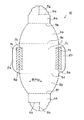
図1は、本発明のスリーブ型カートンの一実施例の内面側の構成を説明する展開図(ブランク板の図)である。
図1の展開図において、スリーブ型カートンのブランク板10は、長方形の底板1を中心として、その左右両側に、それぞれ折目線5a 、5b を介して係止片2a 、2b が連接され、また、上下の両側には、それぞれ折目線5c 、5d を介して側壁板3a 、3b が連接され、更に、該側壁板3a 、3b の先端部には、それぞれ折目線5e 、5f を介して、それぞれ天板形成片4a 、4b が連接されて本体部分が構成されている。
【0023】
そして、上下両側の天板形成片4a 、4b には、それぞれ切目線6a 、6b が設けられており、折目線5c 、5e および折目線5d 、5f を、それぞれ谷折りして側壁板3a 、3b を立ち上げ、また、底板1の上部で天板形成片4a 、4b を重ね合わせた時、天板形成片4a 、4b を互いに差し込んで係合し、天板を形成するための切目線6a と切目線6b とによるロック構造が設けられている。
尚、前記ロック構造を形成する切目線6a 、6b の天板形成片4a 、4b の中心部側の先端部近傍には、この部分から天板形成片4a 、4b のそれぞれの先端部に至る折目線5g と折目線5h とが設けられている。
【0024】
この折目線5g 、5h は、前記切目線6a 、6b を、互いに差し込んで天板形成片4a 、4b を係止する際、それぞれを折り曲げて切目線部が開くようにし、切目線6a と切目線6b との差し込みを容易にするために設けたものである。
従って、前記折目線5g 、5h は、必須ではないが、包装の作業を容易にできる点で設けることが好ましい。
【0025】
また、上下両側の天板形成片4a 、4b の切目線6a 、6b より先の部分は、本実施例では花びら形状としたが、この部分の形状は自由に設計することができ、包装される内容物にマッチした形状を採り、それに応じた表面の絵柄印刷を施すことにより、意匠効果を一層高めることができる。
【0026】
尚、底板1の左右両側の折目線5a 、5b のそれぞれの両側に斜線で示した接着部7a 、7b 、および接着部7c 、7d の領域は、係止片2a 、2b を、それぞれ折目線5a 、5b で底板1側に折り返して接着剤で接着される領域の例を示したものである。
このように係止片2a 、2b は、それぞれの先端部近傍に一定幅の非接着部が形成されるように底板1に接着し、その非接着部を容器の係止部として利用するものである。即ち、前記非接着部の係止片2a 、2b の先端の一定幅の端縁部と底板1との間に形成される間隙部に、包装される容器の両側のフランジ部が差し込まれて保持されるように構成したものである。
【0027】
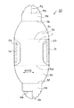
図2は、図1の展開図に示した構成のスリーブ型カートンの底板の左右両側の係止片を接着した仕上がり状態のスリーブ型カートンの内面側を示す平面図である。
即ち、図2において、スリーブ型カートン20は、底板1の左右両側に折目線5a 、5b を介して連接された係止片2a 、2b を、それぞれ折目線5a 、5b により、内側に折り返して、斜線で示す領域を接着剤を介して接着し、接着部7e 、7f が構成されている。その他の各部の構成は、図1の展開図に示したものと同一であるため、説明を省略する。
【0028】
尚、図2に示したスリーブ型カートン20は、先にも説明したように、デザート食品などが充填、密封されたカップ型などのフランジ付き容器を包装するものであり、包装に際しては、容器の上下を逆にして、即ち、フランジ部を下にして、底板1に連接されるいずれか一方の側壁板上に容器を置き、次いで、底板1上にスライドさせて、容器の両側のフランジ部を、スリーブ型カートン20の両側の係止片2a 、2b の各先端部と、底板1との間に形成された非接着部(係止部)に差し込んで、底板1の中央部に配置し、その後、両側の側壁板3a 、3b および天板形成片4a 、4b で容器を包み込むように、折目線5c 、5d および折目線5e 、5f を順次内側に折り曲げて、上部で天板形成片4a 、4b を重ね合わせると共に、天板形成片4a 、4b に設けられたロック構造、即ち、切目線6a と切目線6b とを、折目線5g 、5h を軽く折り曲げながら、互いに差し込んで嵌合させることにより、両側の天板形成片4a 、4b がロックされて上部が閉鎖され包装が完了するものである。
【0029】
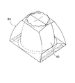
図3は、図2に示した形状のスリーブ型カートンを用いて、フランジ付き容器を、そのフランジ部を下側にして包装した時の状態を示す斜視図である。
図3において、デザート食品などが充填、密封されたフランジ付き容器40は、そのフランジ部を下にして、底板1が四角形状のスリーブ型カートン30で包装され、且つ、そのフランジ部が、スリーブ型カートン30の下部の二方において、両側の係止片2a 、2b の下に差し込まれて底板1との間で保持されると共に、残りの二方が側壁板3a 、3b で閉鎖され、更に、上部が両側の天板形成片4a 、4b をロックして形成される天板により、閉鎖されて包装されているため、スリーブ型カートン30から抜け落ちることがなく、安全に包装される。
【0030】
また、スリーブ型カートン30の側壁板3a 、3b は、紙の目が横方向になるように構成されているので、包装される容器の側壁が曲面で形成されている場合には、これに沿って曲線状に形成することができ、カートン形状にも変化を持たせることができるため、天板形成片4a 、4b の先端部の形状と合わせて、スリーブ型カートン30に造形的な楽しさを加えられ意匠性を向上できる。
【0031】
尚、天板形成片4a 、4b に設けるロック構造は、前記実施例の図における切目線6a 、6b の組合せのほか、一方の天板形成片にフック(鉤)状など戻り止めの付いた差し込み片を設け、もう一方の天板形成片にこれを差し込んで止められる切目線または切り欠きによる受け部を設けて構成することもできる。
【0032】
【発明の効果】
以上詳しく説明したように、請求項1に記載した発明は、フランジ付き容器を包装するために用いるスリーブ型カートンであって、四角形の底板と、該底板の対向する一方の辺の各々に折目線を介して連接された係止片と、前記底板の対抗する他方の辺の各々に折目線を介して連接された側壁板と、該側壁板に折目線を介して連接されると共にロック構造を有する天板形成片とを備えたブランク板からなり、該ブランク板は、前記係止片を前記折目線で折り返して前記係止片と前記底板とを前記折目線の近傍の一部の領域で接着され、前記係止片の先端部と前記底板との間に非接着部からなる係止部が形成され、前記底板に載置した容器を、前記ロック構造同士を係合すると共に、前記係止部に容器のフランジ部を係止して包装するようにしたことを特徴とするスリーブ型カートンである。
このような構成を採ることにより、以下に列記するような、生産性、輸送、保管、経済性、使用後の廃棄性、包装作業の容易性、内容物の保持性、意匠性など総合的に優れた性能のスリーブ型カートンを容易に提供できる効果を奏する。
【0033】
▲1▼スリーブ型カートンの材料が板紙または板紙を基材とする積層シートであるため、加工適性に優れており、通常の折り畳み函(Folding Carton)と同様に、印刷、打抜き、製函(貼り)の工程で自動化された公知の設備を利用して製造できるため生産性に優れており、また、使用後は、焼却も容易で廃棄性にも優れている。
【0034】
▲2▼スリーブ型カートンは、材料の使用量が少なく、製造時、フラットな状態に仕上げられるため嵩張らず、輸送、保管が容易で、コストも安価であり、経済性に優れている。
【0035】
▲3▼使用に際しては、包装する容器を、そのフランジ部を下にして、スリーブ型カートンの底板の両側の係止片の非接着部が形成する両側の係止部の間に、横方向からスライドさせて、フランジ部を底板と係止片の間に挿入し、底板の中央部に置き、次いで、両側の側壁板および天板形成片を、順次折目線で容器を包み込むように折り曲げて、容器の上部で天板形成片を重ね合わせ、両側の天板形成片に設けられたロック構造で両者をロックすることにより、上部が閉鎖され、包装を終了することができる。
このように包装することにより、包装作業が容易であると同時に、被包装物である容器は、上下がスリーブ型カートンの底板と天板で覆われ、側面においては、二方が側壁板で閉鎖され、残りの二方では容器のフランジ部が係止部で挟み込まれて保持されるため、スリーブ型カートンから抜け落ちることがなく、安全に包装される。
【0036】
▲4▼スリーブ型カートンの両側の側壁板は、それぞれの両側が切り放しの形態であるため、自由な形状にデザインすることができ、また、容器の側面の形状に応じて傾斜状、或いは曲線状に形成することもできる。更に、天板形成片の先端部の形状についても、自由な形状にデザインすることができるので、スリーブ型カートンに造形的な美しさを付与することができる。また、上記構造面の特徴に合わせて表面に印刷による加飾を施すことにより、一層優れた意匠性のスリーブ型カートンを提供できる。
【0037】
また、請求項2に記載した発明は、前記ロック構造が、前記天板形成片の端縁から内部に向けて形成された切目線で構成されたことを特徴とする請求項1記載のスリーブ型カートンである。
このような構成を採ることにより、前記請求項1に記載した発明の効果に加えて、内容物の包装に際して、接着剤を使用しなくても、両側の天板形成片の切目線同士を互いに差し込んで係合させるだけで、スリーブ型カートンの上部を閉鎖することができるため、包装作業が容易となり、また、上部で重なり合う天板形成片の端縁部の形状を自由にデザインできるため、カートンに造形的な美しさを付与することができ、意匠性も一層向上させることができる。
【0038】
請求項3に記載した発明は、前記ロック構造が、前記天板形成片の端縁から内部に向けて形成された切目線と、該切目線の終端から前記天板形成片の他の端縁に向けて形成された折目線とから構成されたことを特徴とする請求項1記載のスリーブ型カートンである。
このような構成を採ることにより、前記請求項1または2に記載した発明の効果に加えて、天板形成片の切目線同士を係合させる際、前記折目線を折り曲げることにより切目線が開くため、切目線同士の係合を一層容易に行うことができ、包装の作業性が更に向上する。
【0039】
また、請求項4に記載した発明は、前記切目線が、前記側壁板に天板形成片を連接する折目線と平行に設けられたことを特徴とする請求項2または3に記載のスリーブ型カートンである。
このような構成を採ることにより、前記請求項2または3に記載した発明の効果に加えて、前記切目線同士の差し込みが、横方向への動きに一定されるため、差し込み操作が容易になると共に、形成された天板形成片の係合部がはずれにくくなり、安定した天板を形成できる。
【0040】
そして、請求項5に記載した発明は、前記ブランク板が、前記非接着部となる領域に予め離型層が設けられていることを特徴とする請求項1乃至4のいずれかに記載のスリーブ型カートンである。
このような構成を採ることにより、前記請求項1乃至4に記載した発明の効果に加えて、両側の係止片を、一部の領域(所定の接着部)で底板に接着する際、万一、接着剤が広がって非接着部にはみ出した場合でも、包装に際して、この部分に容器のフランジ部が差し込まれることにより、容易に剥離するので支障なく包装することができ、係止片の貼り作業を安心して高速で行えると共に、包装作業も能率よく行えるようになる。
【図面の簡単な説明】
【図1】本発明のスリーブ型カートンの一実施例の内面側の構成を説明する展開図(ブランク板の図)である。
【図2】図1の展開図に示した構成のスリーブ型カートンの底板の両側の係止片を接着した仕上がり状態のスリーブ型カートンの内面側を示す平面図である。
【図3】図2に示した形状のスリーブ型カートンを用いて、フランジ付き容器を、そのフランジ部を下側にして包装した時の状態を示す斜視図である。
【符号の説明】
1 底板
2a 、2b 係止片
3a 、3b 側壁板
4a 、4b 天板形成片
5a 、5b 、5c 、5d 、5e 、5f 、5g 、5h 折目線
6a 、6b 切目線
7a 、7b 、7c 、7d 、7e 、7f 接着部
10 スリーブ型カートンのブランク板
20 スリーブ型カートン(両側係止片接着済み)
30 スリーブ型カートン
40 フランジ付き容器[0001]
BACKGROUND OF THE INVENTION
The present invention relates to a sleeve-type carton, and more particularly, a sleeve-type carton for packaging a flanged cup-type container filled and sealed with dessert food or the like, wherein the packaged container is securely held, The present invention relates to a sleeve-type carton that does not fall out and is excellent in design.
[0002]
[Prior art]
Conventionally, sleeve-type cartons are mainly used for cup-type containers filled with and sealed with dessert foods such as yogurt, pudding, and various jelly, or for integrated packaging that wraps multiple small cans and bottles together. Since the strength and retention of the packaged items are important, the shape of the carton is uniform, the change is scarce, and there is nothing satisfactory in terms of design.
[0003]
In addition, the sleeve type carton used for individual packaging is also used in part to enhance the design for containers for high-class dessert foods, etc., even if beautiful printing on the carton surface is possible, As the container holding means, for example, a cut line is provided in the corners on both sides of the upper part of the sleeve type carton and held by fitting with the flange part of the container, or a cut line is formed at the edge of the both side corners of the bottom part. And a crease line are provided, and this portion is folded inward to form a locking portion. These are points such as appearance, container holding ability, and troublesome packaging work. However, it had some drawbacks and was not satisfactory.
[0004]
[Problems to be solved by the invention]
The present invention has been made in view of the background as described above, and the object of the present invention is to have a smart appearance and a fun of modeling, excellent design, and contents, that is, a container. It can be easily stored, has excellent retention, is not bulky before and after use, is easy to transport and store, and has excellent disposability after use. In addition, it is to provide an excellent sleeve type carton with high productivity.
[0005]
[Means for Solving the Problems]
The above problems can be solved by the following present invention. That is, the invention described in claim 1 is a sleeve-type carton for packaging a flanged container, and is a rectangular bottom plate and a latch connected to each of a pair of opposing sides of the bottom plate via a crease line. And a side plate connected to each of a pair of opposite sides of the bottom plate via a crease line, and a top plate forming piece connected to the side wall plate via a crease line and having a lock structure In a blank state, the locking piece is folded back at the fold line, and the locking piece and the bottom plate are bonded to each other in the vicinity of the fold line, A locking part composed of a non-adhesive part with a constant width is formed between the tip of the locking piece and the bottom plate, and the locking structures are engaged with each other, and a flange is locked to the locking part. The container placed on the bottom plate is packaged. Consisting of over blanking type carton.
[0006]
By adopting such a configuration, when packaging a flanged container filled with dessert food, etc. and the upper flange part is heat-sealed and sealed with a sleeve-type carton, the container flange part is lowered. Then, the container is slid from the direction in which the side wall plates of the sleeve type carton are connected, and the flange portion is inserted between the bottom plate and the locking piece of the non-bonding portion of the locking pieces on both sides. Place the container on the bottom plate, then fold the side wall plates and top plate forming pieces on both sides in order so as to wrap the container, and overlap the upper part of the container, and the lock structure provided on the top plate forming pieces on both sides By fixing both, the top plate is formed and the packaging is completed.
[0007]
By wrapping in this way, the upper part of the container is covered with the top plate, and in the lower part, the front, rear, left and right are fixed by the side wall plate and the locking piece, so that the container does not fall out of the sleeve type carton. The container can be held.
Further, since the side wall plate of the carton can be formed so as to have an inclination along the side wall of the container, the carton shape is changed, and the design can be improved.
And, in the form in which the container holding means is provided with a score line in the upper and lower crease line portions of the side wall plate of the sleeve type carton, and the corner portion of the container is fitted and held in this portion as in the conventional product Since there is no part, a part of the container does not protrude from the carton, and the appearance is not impaired.
[0008]
According to a second aspect of the present invention, in the sleeve type carton according to the first aspect, the lock structure is constituted by a score line formed inwardly from an end edge of the top plate forming piece. Become.
[0009]
By adopting such a configuration, in addition to the operation and effect of the invention described in claim 1, the packaging lines of the top plate forming pieces can be inserted into each other without using an adhesive when packaging the container. By simply engaging, the top of the carton can be closed, facilitating the packaging operation, and the shape of the edge of the top plate forming piece that overlaps the top can be freely designed, so that the carton can be shaped Fun can be imparted and design can be further improved.
[0010]
According to a third aspect of the present invention, the lock structure includes a cut line formed inwardly from an end edge of the top plate forming piece, and another end edge of the top plate forming piece from the end of the cut line. The sleeve-type carton according to claim 1, wherein the sleeve-type carton is formed of a crease line formed toward the head.
[0011]
By adopting such a configuration, in addition to the operation and effect of the invention described in claim 1 or 2, when the cut lines of the top plate forming pieces are engaged with each other, the cut line is folded by bending the crease line. Therefore, the cut lines can be more easily engaged with each other, and the workability of packaging is improved.
[0012]
According to a fourth aspect of the present invention, in the sleeve type according to the second or third aspect, the cut line is provided in parallel to a crease line connecting the top plate forming pieces to the side wall plate. Consists of cartons.
[0013]
By adopting such a configuration, in addition to the operation and effect of the invention described in claim 2 or 3, when inserting the cut lines, the operation can be fixed in the lateral direction, so that the insertion becomes easy. The engaging portion of the formed top plate forming piece is difficult to come off, and a stable top plate is formed.
[0014]
According to a fifth aspect of the present invention, in the sleeve according to any one of the first to fourth aspects, a release layer is provided in advance in a region where the blank plate becomes the non-bonded portion. Made of type carton.
Such a release layer can be easily provided by printing a resin composition having peelability on the adhesive in a predetermined pattern.
[0015]
And by adopting such a configuration, in addition to the operation and effect of the invention described in claims 1 to 4, the locking piece is bonded to the bottom plate only in a part of the vicinity along the crease line. Even if the adhesive spreads and protrudes to the non-adhesive part, the container flange part is inserted into the non-adhesive part, so that it can be easily peeled off and can be wrapped without any trouble. The pasting operation can be easily performed.
[0016]
DETAILED DESCRIPTION OF THE INVENTION
Embodiments of the sleeve type carton of the present invention will be described below.
The material used for the sleeve type carton of the present invention is mainly paper, and any paperboard having an appropriate thickness and rigidity can be used.
In order to improve the wrinkle, appearance, and design, it is preferable to provide a pattern or other decoration on the surface or both front and back surfaces by printing or the like. For this purpose, various white paperboards having excellent printability are preferable.
[0017]
In addition to the paper board alone, for example, a paper board in which a plastic film such as an aluminum foil, polypropylene, polyethylene, polyethylene terephthalate, or polyvinyl chloride is laminated on the surface can be used.
By using such laminated paperboard, in addition to the appearance such as gloss and smoothness of the surface, water resistance and further performance such as strength can be improved.
[0018]
The manufacturing method of the sleeve type carton of the present invention manufactured using such a material is the same as the normal folding carton (Folding Carton) in the steps of printing, punching, and iron making (specifically, side bonding). It can be efficiently produced by known equipment.
In other words, printing may be any plate type such as lithographic printing, gravure printing, flexographic printing, screen printing, etc., as long as it is a paperboard type printing machine, it can be freely selected, and productivity is achieved on one side or both sides using a multi-sided printing plate Can print well.
[0019]
For punching, a normal folding carton punching machine is used, for example, by using a multi-faced punching die with a pattern as shown in FIG. The blank board (drawn dough) can be manufactured with high productivity.
[0020]
Also, with respect to iron making (side pasting), when the blank plate of the sleeve type carton (drawn dough) has a shape as shown in FIG. A sleeve type carton can be manufactured with high productivity by applying an adhesive of an emulsion type or the like to the adhesive portion of the bottom plate, folding the locking piece inward along the crease line, and press-bonding.
[0021]
【Example】
Hereinafter, the present invention will be described more specifically with reference to the drawings.
However, the present invention is not limited to the embodiments shown in the drawings. In the different drawings, the same parts are denoted by the same reference numerals.
[0022]
FIG. 1 is a development view (drawing of a blank plate) for explaining the configuration of the inner surface side of one embodiment of the sleeve type carton of the present invention.
In the developed view of FIG. 1, the
[0023]
The top
In the vicinity of the front end of the top
[0024]
The crease lines 5g and 5h are formed so that when the
Therefore, the
[0025]
Moreover, although the part ahead of the
[0026]
Note that the areas of the
As described above, the locking
[0027]
FIG. 2 is a plan view showing the inner surface side of the sleeve-type carton in a finished state in which the engagement pieces on both the left and right sides of the bottom plate of the sleeve-type carton having the configuration shown in the development view of FIG. 1 are bonded.
That is, in FIG. 2, the
[0028]
As described above, the
[0029]
FIG. 3 is a perspective view showing a state when a flanged container is packaged with the flange portion on the lower side using the sleeve type carton having the shape shown in FIG.
In FIG. 3, a
[0030]
Further, the
[0031]
In addition to the combination of the
[0032]
【The invention's effect】
As described above in detail, the invention described in claim 1 is a sleeve type carton used for packaging a flanged container, and includes a quadrangular bottom plate and a crease line on each of opposite sides of the bottom plate. A locking piece connected via a crease line, a locking plate connected to the side wall plate via a crease line, and a locking structure connected to each of the opposite sides of the bottom plate via a crease line The blank plate is provided with a top plate forming piece, and the blank plate folds the locking piece along the fold line, and the locking piece and the bottom plate are partly in the vicinity of the fold line. A locking portion formed of a non-bonding portion is formed between the tip end portion of the locking piece and the bottom plate, and the container placed on the bottom plate is engaged with the lock structures and Lock the flange part of the container to the stopper and wrap it. It is a sleeve-type carton according to claim.
By adopting such a configuration, productivity, transportation, storage, economy, disposal after use, ease of packaging work, content retention, design, etc., as listed below The effect is that it is possible to easily provide a sleeve type carton having excellent performance.
[0033]
(1) Since the material of the sleeve-type carton is paperboard or a laminated sheet based on paperboard, it is excellent in processability, and in the same way as a normal folding box (Folding Carton), printing, punching, box making (pasting) ), It can be manufactured using known equipment automated in the process of (), so that it is excellent in productivity, and after use, it is easy to incinerate and excellent in disposal.
[0034]
{Circle around (2)} The sleeve type carton has a small amount of material used, is finished in a flat state at the time of manufacture, is not bulky, is easy to transport and store, is inexpensive, and is economical.
[0035]
(3) In use, the container to be packaged is placed from the lateral direction between the engaging parts on both sides formed by the non-adhesive parts of the engaging pieces on both sides of the bottom plate of the sleeve type carton with the flange part facing down. Slide the flange part between the bottom plate and the locking piece, place it in the center of the bottom plate, then fold the side wall plate and the top plate forming piece on both sides so as to wrap the container at the crease line sequentially, By overlapping the top plate forming pieces on the upper part of the container and locking them with the lock structure provided on the top plate forming pieces on both sides, the upper part is closed and the packaging can be finished.
By packaging in this way, the packaging work is easy, and at the same time, the container, which is the package, is covered with the bottom plate and the top plate of the sleeve type carton on the top and bottom, and the two sides are closed with the side wall plate In the remaining two sides, since the flange portion of the container is sandwiched and held by the locking portion, the container can be safely packaged without falling off from the sleeve type carton.
[0036]
(4) The side wall plates on both sides of the sleeve type carton can be designed to have any shape because both sides are cut off, and can be designed to be inclined or curved according to the shape of the side of the container. It can also be formed. Furthermore, since the shape of the tip part of the top plate forming piece can also be designed in a free shape, it is possible to impart a cosmetic beauty to the sleeve type carton. Moreover, the sleeve type carton of the further outstanding design property can be provided by giving the surface decoration according to the characteristic of the said structural surface by printing.
[0037]
According to a second aspect of the present invention, in the sleeve mold according to the first aspect, the lock structure is constituted by a score line formed inwardly from an end edge of the top plate forming piece. A carton.
By adopting such a configuration, in addition to the effect of the invention described in claim 1, the packaging lines of the contents can be connected to each other without using an adhesive, so that the cut lines on the top plate forming pieces on both sides can be connected to each other. The upper part of the sleeve-type carton can be closed simply by inserting and engaging, so the packaging work is easy, and the shape of the edge of the top plate forming piece that overlaps the upper part can be designed freely. It is possible to impart a aesthetic beauty to the skin and to further improve the design.
[0038]
According to a third aspect of the present invention, the lock structure includes a cut line formed inwardly from an end edge of the top plate forming piece, and another end edge of the top plate forming piece from the end of the cut line. 2. The sleeve type carton according to claim 1, wherein the sleeve type carton is formed of a crease line formed toward the head.
By adopting such a configuration, in addition to the effect of the invention described in claim 1 or 2, when the cut lines of the top plate forming pieces are engaged with each other, the cut lines are opened by bending the fold lines. For this reason, the cut lines can be more easily engaged with each other, and the packaging workability is further improved.
[0039]
According to a fourth aspect of the present invention, in the sleeve type according to the second or third aspect, the cut line is provided in parallel to a crease line connecting the top plate forming pieces to the side wall plate. A carton.
By adopting such a configuration, in addition to the effect of the invention described in claim 2 or 3, the insertion between the score lines is fixed to the movement in the lateral direction, so that the insertion operation is facilitated. At the same time, the engaging portions of the formed top plate forming pieces are not easily detached, and a stable top plate can be formed.
[0040]
According to a fifth aspect of the present invention, in the sleeve according to any one of the first to fourth aspects, a release layer is provided in advance in a region where the blank plate becomes the non-bonded portion. Type carton.
By adopting such a configuration, in addition to the effects of the inventions described in the first to fourth aspects, when the locking pieces on both sides are bonded to the bottom plate in some areas (predetermined bonding portions), 1. Even when the adhesive spreads and protrudes to the non-adhesive part, the flange part of the container is inserted into this part when packaging, so it can be easily peeled off and can be wrapped without any trouble. Work can be done at high speed with peace of mind, and packaging can be done efficiently.
[Brief description of the drawings]
FIG. 1 is a development view (drawing of a blank plate) illustrating a configuration of an inner surface side of an embodiment of a sleeve type carton according to the present invention.
2 is a plan view showing an inner surface side of a finished sleeve type carton in which the engagement pieces on both sides of the bottom plate of the sleeve type carton having the configuration shown in the developed view of FIG. 1 are bonded. FIG.
3 is a perspective view showing a state when a flanged container is packaged with the flange portion on the lower side using the sleeve type carton having the shape shown in FIG. 2. FIG.
[Explanation of symbols]
1
10 Sleeve type carton blank board
20 Sleeve type carton
30 sleeve carton
40 Flanged container
Claims (5)
四角形の底板と、該底板の対向する一対の辺の各々に折目線を介して連接された係止片と、前記底板の対向する他の一対の辺の各々に折目線を介して連接された側壁板と、該側壁板に折目線を介して連接されると共に、ロック構造を有する天板形成片とを備えたブランク板から組み立てられ、
ブランクの状態で、前記係止片を前記折目線で折り返して、前記係止片と前記底板とを前記折目線の近傍の一部の領域で接着し、前記係止片の先端部と前記底板との間に一定幅の非接着部からなる係止部を形成し、前記ロック構造同士を係合すると共に、前記係止部にフランジを係止して前記底板に載置した容器を包装するようにしたことを特徴とするスリーブ型カートン。A sleeve-type carton for packaging flanged containers,
A square bottom plate, a locking piece connected to each of a pair of opposing sides of the bottom plate via a crease line, and a pair of opposing sides of the bottom plate connected to each of a pair of opposing sides via a crease line Assembled from a blank plate provided with a side wall plate and a top plate forming piece having a lock structure connected to the side wall plate through a crease line,
In a blank state, the locking piece is folded back at the fold line, and the locking piece and the bottom plate are bonded to each other in a part of the vicinity of the fold line, and the leading end portion of the locking piece and the bottom plate A locking portion composed of a non-adhesive portion having a constant width is formed between the locking structure and the lock structures to engage with each other, and a flange is locked to the locking portion to wrap the container placed on the bottom plate. A sleeve-type carton characterized by doing so.
Priority Applications (1)
| Application Number | Priority Date | Filing Date | Title |
|---|---|---|---|
| JP05115897A JP3908321B2 (en) | 1997-02-20 | 1997-02-20 | Sleeve type carton |
Applications Claiming Priority (1)
| Application Number | Priority Date | Filing Date | Title |
|---|---|---|---|
| JP05115897A JP3908321B2 (en) | 1997-02-20 | 1997-02-20 | Sleeve type carton |
Publications (2)
| Publication Number | Publication Date |
|---|---|
| JPH10236523A JPH10236523A (en) | 1998-09-08 |
| JP3908321B2 true JP3908321B2 (en) | 2007-04-25 |
Family
ID=12879028
Family Applications (1)
| Application Number | Title | Priority Date | Filing Date |
|---|---|---|---|
| JP05115897A Expired - Fee Related JP3908321B2 (en) | 1997-02-20 | 1997-02-20 | Sleeve type carton |
Country Status (1)
| Country | Link |
|---|---|
| JP (1) | JP3908321B2 (en) |
Families Citing this family (2)
| Publication number | Priority date | Publication date | Assignee | Title |
|---|---|---|---|---|
| JP2013154047A (en) * | 2012-01-31 | 2013-08-15 | Dainippon Printing Co Ltd | Package body of round rice cake, packaging material for round rice cake, method for assembling thereof, round rice cake set, and decoration method of round rice cake |
| JP2013154931A (en) * | 2012-01-31 | 2013-08-15 | Dainippon Printing Co Ltd | Packaging body of round rice cakes, packaging material for round rice cakes, method of assembling the same, set of the round rice cakes, and method of decorating round rice cakes |
-
1997
- 1997-02-20 JP JP05115897A patent/JP3908321B2/en not_active Expired - Fee Related
Also Published As
| Publication number | Publication date |
|---|---|
| JPH10236523A (en) | 1998-09-08 |
Similar Documents
| Publication | Publication Date | Title |
|---|---|---|
| GB2209327A (en) | A packing container for liquid contents | |
| KR20060012311A (en) | Product Packing Method | |
| US20100257821A1 (en) | Soap bar wrapper | |
| JP3908321B2 (en) | Sleeve type carton | |
| JP3853457B2 (en) | Liquid paper container | |
| JP3605434B2 (en) | Semi-solid paper container | |
| JPH0826342A (en) | Bi-fold carton | |
| EP1568614B1 (en) | Paper container | |
| JPH0826260A (en) | Bi-fold carton | |
| JP4220086B2 (en) | Paper cup container with paper holder | |
| JPH0880936A (en) | One-touch opening / closing carton | |
| AU2002310184A1 (en) | Soap bar wrapper | |
| JP4580549B2 (en) | Body carton | |
| JP2582654Y2 (en) | Powder packaging container | |
| CN223619136U (en) | Packing box | |
| JP3923554B2 (en) | Liquid paper container | |
| US6471123B1 (en) | Folding carton with pressure-activated closure mechanism | |
| JP7651989B2 (en) | Web corner type paper container | |
| JP3883617B2 (en) | Carton blank with window and carton with window | |
| JP4729790B2 (en) | Body carton | |
| JP3624022B2 (en) | Volume reduction carton | |
| JPH044218B2 (en) | ||
| JP4076600B2 (en) | Tamper-proof carton | |
| JPS61217343A (en) | Packaging paperboard carton and manufacture thereof | |
| JP4498599B2 (en) | Body carton |
Legal Events
| Date | Code | Title | Description |
|---|---|---|---|
| A621 | Written request for application examination |
Free format text: JAPANESE INTERMEDIATE CODE: A621 Effective date: 20040217 |
|
| A131 | Notification of reasons for refusal |
Free format text: JAPANESE INTERMEDIATE CODE: A131 Effective date: 20060711 |
|
| A521 | Written amendment |
Free format text: JAPANESE INTERMEDIATE CODE: A523 Effective date: 20060908 |
|
| A131 | Notification of reasons for refusal |
Free format text: JAPANESE INTERMEDIATE CODE: A131 Effective date: 20060926 |
|
| A521 | Written amendment |
Free format text: JAPANESE INTERMEDIATE CODE: A523 Effective date: 20061127 |
|
| TRDD | Decision of grant or rejection written | ||
| A01 | Written decision to grant a patent or to grant a registration (utility model) |
Free format text: JAPANESE INTERMEDIATE CODE: A01 Effective date: 20061221 |
|
| A61 | First payment of annual fees (during grant procedure) |
Free format text: JAPANESE INTERMEDIATE CODE: A61 Effective date: 20070118 |
|
| R150 | Certificate of patent (=grant) or registration of utility model |
Free format text: JAPANESE INTERMEDIATE CODE: R150 |
|
| LAPS | Cancellation because of no payment of annual fees |