JP3908154B2 - Fuel cell system - Google Patents
Fuel cell system Download PDFInfo
- Publication number
- JP3908154B2 JP3908154B2 JP2002333520A JP2002333520A JP3908154B2 JP 3908154 B2 JP3908154 B2 JP 3908154B2 JP 2002333520 A JP2002333520 A JP 2002333520A JP 2002333520 A JP2002333520 A JP 2002333520A JP 3908154 B2 JP3908154 B2 JP 3908154B2
- Authority
- JP
- Japan
- Prior art keywords
- fuel cell
- flow rate
- cell stack
- refrigerant
- oxidant gas
- Prior art date
- Legal status (The legal status is an assumption and is not a legal conclusion. Google has not performed a legal analysis and makes no representation as to the accuracy of the status listed.)
- Expired - Fee Related
Links
Images


Classifications
-
- Y—GENERAL TAGGING OF NEW TECHNOLOGICAL DEVELOPMENTS; GENERAL TAGGING OF CROSS-SECTIONAL TECHNOLOGIES SPANNING OVER SEVERAL SECTIONS OF THE IPC; TECHNICAL SUBJECTS COVERED BY FORMER USPC CROSS-REFERENCE ART COLLECTIONS [XRACs] AND DIGESTS
- Y02—TECHNOLOGIES OR APPLICATIONS FOR MITIGATION OR ADAPTATION AGAINST CLIMATE CHANGE
- Y02E—REDUCTION OF GREENHOUSE GAS [GHG] EMISSIONS, RELATED TO ENERGY GENERATION, TRANSMISSION OR DISTRIBUTION
- Y02E60/00—Enabling technologies; Technologies with a potential or indirect contribution to GHG emissions mitigation
- Y02E60/30—Hydrogen technology
- Y02E60/50—Fuel cells
Landscapes
- Fuel Cell (AREA)
Description
【0001】
【発明の属する技術分野】
この発明は、燃料電池システムにおける酸化剤ガスに対する加湿制御に関するものである。
【0002】
【従来の技術】
燃料電池自動車等に搭載される燃料電池システムには、固体高分子電解質膜の両側にアノードとカソードを設けた単セルをセパレータを介して複数積層してなる燃料電池スタックを備えるものがある。この燃料電池スタックでは、アノードに燃料ガス(例えば水素ガス)を供給し、カソードに酸化剤ガス(例えば酸素あるいは空気)を供給すると、アノードで水素ガスがイオン化して固体高分子電解質中を移動し、電子は、外部負荷を通ってカソードに移動し、酸素と反応して水を生成する一連の電気化学反応による電気エネルギを取り出すことができる。このようにカソード側に水が生じるため、燃料電池から排出される未反応の酸化剤ガス(以下、酸化剤オフガスという)は水分含量が多い。
【0003】
また、燃料電池スタックは発電する際に発熱を伴うが、燃料電池には作動温度範囲があるため燃料電池が上限温度以上に昇温しないように冷却する必要がある。そのため、燃料電池スタックには冷却流路が設けられており、この冷却流路に冷媒を流して熱を奪い燃料電池を冷却している。
【0004】
ところで、前記燃料電池スタックにあっては、固体高分子電解質膜が乾燥してしまうと、イオン伝導率が低下し、エネルギ変換効率が低下してしまうので、良好なイオン伝導性を保つために固体高分子電解質膜に水分を供給する必要がある。
このため、この種の燃料電池スタックでは、燃料電池に供給する前に予め燃料ガスあるいは酸化剤ガスを加湿器で加湿し、加湿されたこれらガスを固体高分子電解質膜に供給することにより、固体高分子電解質膜に水分を供給している。
【0005】
酸化剤ガスを加湿する加湿器の一つとして、水蒸気透過膜を間に挟んで酸化剤ガスと酸化剤オフガスを流し、水蒸気透過膜を介して酸化剤オフガス中の水分を酸化剤ガスに受け渡す、換言すると、酸化剤オフガスから水分を回収してこの水分を酸化剤ガスに循環させるようにした加湿器が提案されている(例えば、特許文献1参照)。しかしながら、この加湿器では、加湿量の制御が困難で、酸化剤ガスに対する加湿の程度は成り行きにならざるを得なかった。その結果、加湿器内で酸化剤オフガスが冷却され酸化剤オフガス中の水分が凝縮して、酸化剤ガスに対する加湿量が不足したり、その逆に、酸化剤ガスに対する加湿量が過度になって燃料電池スタック内でフラッディングが生じ、発電能力が低下するなどの問題が生じた。
【0006】
この問題を解決するものとして、特許文献2、特許文献3、特許文献4等に開示された燃料電池システムが提案されている。
特許文献2に開示された燃料電池システムでは、前記加湿器をバイパスして酸化剤オフガスを流すことが可能なバイパス流路と、酸化剤オフガスを前記加湿器と前記バイパス流路のいずれに流すか切り換える切替弁を備え、切替弁の切り換えにより酸化剤オフガスの流路制御を行い、酸化剤オフガスを加湿器に流すか、加湿器を迂回させて流すかして、酸化剤ガスに対する加湿量を制御している。
【0007】
また、特許文献3に開示された燃料電池システムでは、前記加湿器をバイパスして酸化剤ガスを流すことが可能なバイパス流路と、このバイパス流路を流れる酸化剤ガスの流量制御を行う流量制御弁を備え、前記流量制御弁を開くことにより、加湿されない酸化剤ガスと加湿器で加湿された酸化剤ガスとを混合して燃料電池スタックに供給可能にし、さらに前記流量制御弁の開度を制御することにより混合比を変え、これにより酸化剤ガス全体としての加湿量を制御にしている。
【0008】
さらに、特許文献4に開示された燃料電池システムでは、燃料電池スタックを出た冷媒を前記加湿器回りに流す加熱流路を備え、この加熱流路に冷媒を流すことにより、燃料電池スタックを冷却したことで昇温した冷媒で前記加湿器を加熱し、加湿器内での酸化剤オフガスの温度低下を防止することにより、酸化剤オフガス中の水分の凝縮を防止して、酸化剤ガスに対する加湿量低下を防止している。
【0009】
【特許文献1】
特開平6−132038号公報
【特許文献2】
特開2000−164231号公報、
【特許文献3】
特開2001−216984号公報、
【特許文献4】
特開2001−216981号公報
【0010】
【発明が解決しようとする課題】
しかしながら、これら特許文献に開示された従来の燃料電池システムにおいては、加湿量の制御は可能になるものの、バイパス流路、切替弁、流量制御弁、加熱流路などの機器類およびこれらを接続する配管が必要になるので、部品点数が多くなり、システムの大型化を招き、コスト増になるなどの問題があった。
そこで、この発明は、簡単な構成ながら、酸化剤ガスに対する加湿量制御が可能な燃料電池システムを提供するものである。
【0011】
【課題を解決するための手段】
上記課題を解決するために、請求項1に記載した発明は、固体高分子電解質膜の両側にアノードとカソードを設けた単セルをセパレータを介して複数積層した燃料電池スタック(例えば、後述する実施の形態における燃料電池スタック1)と、該燃料電池スタックに設けられた冷却流路に冷媒(例えば、後述する実施の形態における冷却水)を供給する冷媒供給手段(例えば、後述する実施の形態における冷却水ポンプ9)と、前記燃料電池スタックのアノードに燃料ガス(例えば、後述する実施の形態における水素ガス)を供給する燃料ガス供給手段(例えば、後述する実施の形態における水素供給装置5)と、前記燃料電池スタックのカソードに酸化剤ガス(例えば、後述する実施の形態における空気)を供給する酸化剤ガス供給手段(例えば、後述する実施の形態におけるエアコンプレッサ2)と、前記カソードに供給される酸化剤ガスと前記カソードから排出された酸化剤オフガス(例えば、後述する実施の形態における空気オフガス)とを水分透過膜を隔てて流通させ前記酸化剤オフガス中の水分を前記酸化剤ガスに回収する水回収循環手段(例えば、後述する実施の形態における加湿器3)と、を備えた燃料電池システムにおいて、酸化剤ガス流量が多いほど必要水蒸気流量が多くなるように設定されたマップを参照して前記燃料電池スタックに供給される前記酸化剤ガスの流量に応じた必要水蒸気流量を算出する必要水蒸気流量算出手段(例えば、後述する実施の形態におけるステップS105,S107,S109)と、前記必要水蒸気流量算出手段で算出された必要水蒸気流量を得るために必要な燃料電池スタック出口の目標冷媒温度を算出する目標冷媒出口温度算出手段(例えば、後述する実施の形態におけるステップS111)と、を備え、前記燃料電池スタックの出口における冷媒温度が前記目標冷媒出口温度算出手段により算出された目標冷媒温度となるように前記冷却流路に供給する冷媒の流量を制御して酸化剤オフガス中の水分量を変化させることにより、前記燃料電池スタックに供給される酸化剤ガスの水分量を制御することを特徴とする。
【0012】
このように構成することにより、バイパス流路等の特別な機器類を設けないで、酸化剤ガスを最適な加湿量に制御することが可能になり、燃料電池スタックに流入する加湿水蒸気量を最適に制御することが可能になる。
【0013】
請求項2に記載した発明は、請求項1に記載の発明において、前記燃料電池スタックの負荷変動の速度に応じた遅れ時間を有して前記冷媒の流量を制御することを特徴とする。
このように構成することにより、燃料電池スタックの負荷増大時における加湿遅れや、負荷減少時における燃料電池スタック内の生成水排除不良を未然に防止することが可能になる。なお、例えば燃料電池自動車駆動用の燃料電池スタックの場合には、燃料電池スタックの負荷変動とは加速あるいは減速に対応し、負荷変動の速度とは加速度あるいは減速度に対応し、定速走行は負荷変動なしに対応する。
【0014】
請求項3に記載した発明は、固体高分子電解質膜の両側にアノードとカソードを設けた単セルをセパレータを介して複数積層した燃料電池スタック(例えば、後述する実施の形態における燃料電池スタック1)と、該燃料電池スタックに設けられた冷却流路に冷媒(例えば、後述する実施の形態における冷却水)を供給する冷媒供給手段(例えば、後述する実施の形態における冷却水ポンプ9)と、前記燃料電池スタックのアノードに燃料ガス(例えば、後述する実施の形態における水素ガス)を供給する燃料ガス供給手段(例えば、後述する実施の形態における水素供給装置5)と、前記燃料電池スタックのカソードに酸化剤ガス(例えば、後述する実施の形態における空気)を供給する酸化剤ガス供給手段(例えば、後述する実施の形態におけるエアコンプレッサ2)と、前記カソードに供給される酸化剤ガスと前記カソードから排出された酸化剤オフガス(例えば、後述する実施の形態における空気オフガス)とを水分透過膜を隔てて流通させ前記酸化剤オフガス中の水分を前記酸化剤ガスに回収する水回収循環手段(例えば、後述する実施の形態における加湿器)と、を備えた燃料電池システムにおいて、酸化剤ガス流量が多いほど必要水蒸気流量が多くなるように設定されたマップを参照して前記燃料電池スタックに供給される前記酸化剤ガスの流量に応じた必要水蒸気流量を算出する必要水蒸気流量算出手段(例えば、後述する実施の形態におけるステップS105,S107,S109)と、前記燃料電池スタックのセル電圧を検出するセル電圧検出手段(例えば、後述する実施の形態におけるセル電圧検出装置15)と、前記セル電圧検出手段により検出されたセル電圧に基づいて前記燃料電池スタックから放出される放熱量を算出する放熱量算出手段(例えば、後述する実施の形態におけるステップS110)と、前記必要水蒸気流量算出手段で算出された必要水蒸気流量を得るために必要な燃料電池スタック出口の目標冷媒温度を算出する目標冷媒出口温度算出手段(例えば、後述する実施の形態におけるステップS111)と、前記燃料電池スタック入口の冷媒温度を検出する冷媒入口温度検出手段(例えば、後述する実施の形態における冷却水入口温度センサ13)と、前記放熱量算出手段により算出された放熱量、および前記冷媒入口温度検出手段で検出された冷媒入口温度と前記目標冷却水出口温度算出手段によって算出された目標冷媒出口温度との温度差に基づいて、前記冷媒が前記冷却流路を流通したときに前記燃料電池スタックから受け取る熱量と前記放熱量とが同じになるように燃料電池スタックに供給すべき目標冷媒流量を算出する冷媒流量算出手段(例えば、後述する実施の形態におけるステップS113)と、前記燃料電池スタックに前記目標冷媒流量の冷媒が供給されるように前記冷媒供給手段を制御する冷媒流量制御手段(例えば、後述する実施の形態におけるステップS201〜S207)と、を備えることを特徴とする。
【0015】
このように構成することにより、放熱量算出手段で算出した放熱量と、冷媒が燃料電池スタックを冷却する際に燃料電池スタックから受け取る熱量が同じになるように制御することができる。そして、冷媒出口温度と酸化剤オフガス出口温度はほぼ比例関係にあるので、冷媒流量制御手段により冷媒流量を制御するだけで、酸化剤ガスを最適な加湿量に制御することが可能になり、燃料電池スタックに流入する加湿水蒸気量を最適に制御することが可能になる。しかも、そのためのバイパス流路等の特別な機器類は不要である。
【0016】
請求項4に記載した発明は、請求項3に記載の発明において、前記燃料電池スタックの負荷変動の速度に応じて、前記冷媒流量制御手段による目標冷媒流量への流量制御開始に遅れ時間を設定する遅れ時間設定手段(例えば、後述する実施の形態におけるステップS105,S107,S109)を備えることを特徴とする。
このように構成することにより、燃料電池スタックの負荷増大時における加湿遅れや、負荷減少時における燃料電池スタック内の生成水排除不良を未然に防止することが可能になる。なお、例えば燃料電池自動車駆動用の燃料電池スタックの場合には、燃料電池スタックの負荷変動とは加速あるいは減速に対応し、負荷増大時とは加速時、負荷減少時とは減速時に対応し、定速走行は負荷変動なしに対応する。
【0017】
【発明の実施の形態】
以下、この発明に係る燃料電池システムの一実施の形態を図1から図10の図面を参照して説明する。
この発明に係る燃料電池システムは、燃料電池スタックのカソードから排出される酸化剤ガスのオフガス(以下、酸化剤オフガスという)から水分を回収し、回収した水分を、カソードに供給される酸化剤ガスに供給する加湿器(水回収循環手段)を備えていて、燃料電池スタックを冷却する冷媒の流量を制御することにより、酸化剤ガスに対する加湿量を最適に制御するようにしているが、初めにその原理について図7および図8を参照して説明する。なお、この原理説明において「燃料電池」は燃料電池スタックと同義である。
【0018】
図7に示すように、燃料電池における発電に伴う発熱を、燃料電池内を流れる冷媒(例えば、冷却水)で冷却する燃料電池システムにおいては、燃料電池内の温度は熱容量の大きい冷媒の温度に大きく依存し、冷媒出口温度は、冷媒流量に敏速に反応する。
ここで、燃料電池における熱収支は次の通りである。
燃料電池における発電に伴う発熱量Qは、次式(1)から求めることができる。
Q=I×(V0−V)×n ・・・ (1)式
ここで、Iは電流、V0は発熱量基準電圧、Vはセル電圧、nはセル数である。
【0019】
また、燃料電池を冷却する冷媒が受け取る熱量Qcは、次式(2)から求めることができる。
Qc=Fc×ρ×c×(Tc2−Tc1) ・・・ (2)式
ここで、Fcは冷媒流量、ρは冷媒の密度、cは冷媒の比熱、Tc2は冷媒出口温度、Tc1は冷媒入口温度である。
また、加湿器により得られる加湿水蒸気量Fvは、次式(3)から求めることができる。
Fv=c1×f(Tg2) ・・・ (3)式
ここで、Tg2は燃料電池から排出される酸化剤オフガスの温度(以下、酸化剤オフガス出口温度という)、c1は係数である。
【0020】
ところで、この燃料電池システムにおいては、酸化剤オフガス出口温度Tg2と冷媒出口温度Tc2はほぼ比例関係にあることが、実験的に判明している。図8は、実験結果の一例であり、この実験結果から、冷媒出口温度Tc2は、燃料ガス(水素ガス)出口温度Th2よりも酸化剤オフガス出口温度Tg2の方により比例関係に近いことがわかる。
したがって、(1),(2),(3)式から、冷媒流量Fcにより、冷媒出口温度Tc2および酸化剤オフガス出口温度Tg2が制御され、燃料電池に流入する加湿水蒸気量を制御することができることとなる。
【0021】
また、燃料電池の負荷に応じた必要水分量Frは、次式(4)から求めることができる。
Fr=Fgin×{Pwin(Tdin)/(Pgin−Pwin(Tdin))} ・・・ (4)式
ここで、Fgin[NLM]はある負荷における入口ガス流量(ドライ基準)、Tdin[゜C]は必要入口ガス露点、Pgin[Pa abs]は入口ガス圧力(ウェット基準)、Pwin(Tdin)[Pa]は露点Tdinにおける水蒸気分圧である。なお、燃料電池車両では燃料電池の負荷はアクセル開度に対応する。
【0022】
したがって、冷媒入口温度Tc1をモニターし、Fv=Frとなるように、冷媒出口温度Tc2を制御すれば、酸化剤ガスを最適な加湿状態に制御することが可能になり、したがって、冷媒出口温度Tc2となるように冷媒流量を制御すれば、酸化剤ガスを最適な加湿状態に制御することが可能になる。これが、本発明における燃料電池の加湿制御の原理である。
【0023】
また、車輌駆動用の燃料電池(燃料電池スタック)では、加速時の負荷変動に対して加湿遅れが生じ、燃料電池の電圧が下がる虞があるので、本発明では、図9に示すように、加速時にはすぐに冷媒流量を増やさず、加速開始から所定時間だけ冷媒流量を減少(現状維持を含む)させることにより、冷媒出口温度を上げて加湿量を増大させ、これにより加湿遅れを防止して、燃料電池の電圧の低下を防止するようにした。そして、前記所定時間経過後に加速の程度に応じた加湿制御を行うようにした。
【0024】
一方、車輌駆動用の燃料電池(燃料電池スタック)では、減速時、反応ガスの流量が減少すると、燃料電池内で生じた生成水を排除できなくなり、フラッディングが起こって電圧が不安定になる虞があるので、本発明では、図10に示すように、減速時にはすぐに冷媒流量を減少させず、減速開始から所定時間だけ冷媒流量を変化させないことにより、冷媒出口温度を下げて加湿量を減少させ、これにより生成水の生成量を減少させて、電圧の安定化を図っている。
【0025】
次に、図1から図6を参照して、本発明に係る燃料電池システムを具体的に説明する。なお、この実施の形態は、燃料電池車両に搭載された燃料電池システムに適用した態様である。
図1は燃料電池システムの概略構成図である。燃料電池スタック1は、例えば固体ポリマーイオン交換膜等からなる固体高分子電解質膜をアノードとカソードとで両側から挟み込んで形成された単セルをセパレータを介して複数積層して構成されており、アノードには燃料ガスとして水素ガスが、カソードには酸化剤ガスとして酸素を含む空気が供給可能になっている。そして、アノードで触媒反応により発生した水素イオンが、固体高分子電解質膜を通過してカソードまで移動して、カソードで酸素と電気化学反応を起こして発電し、水が生成される。
【0026】
また、燃料電池スタック1は、前記セパレータに近接して設けられ冷却液(冷媒)が供給される冷却流路を備えており、発電に伴う発熱により燃料電池1が上限温度を越えないように、前記冷却流路を流れる冷却液で熱を奪い冷却するようになっている。
【0027】
外気はエアコンプレッサ(酸化剤ガス供給手段)2によって加圧され、カソード加湿器(水回収循環手段)3で加湿されて燃料電池スタック1のカソードに供給され、この空気中の酸素が酸化剤として発電に供された後、燃料電池スタック1から空気オフガス(酸化剤オフガス)として排出され、圧力制御弁4を介して大気に放出される。エアコンプレッサ2は、燃料電池スタック1に要求されている出力に応じた質量の空気がカソードに供給されるように回転数制御され、また、圧力制御弁4は、空気極での空気の供給圧が燃料電池スタック1の運転状態に応じた圧力値となるように開度制御される。
【0028】
カソード加湿器3は、例えば中空糸加湿器からなり、空気オフガスから水分を回収し、回収した水分を、燃料電池スタック1へ供給される空気に与えて該空気を加湿する。なお、中空糸加湿器とは、多数の中空糸膜を収容してなり、中空糸膜の内側と外側にそれぞれ水分含量の異なる流体を供給すると、水分含量の多い流体中の水分が中空糸膜を透過して水分含量の少ない流体へと移動する性質を利用して、加湿器としたものである。そして、加湿された空気が燃料電池スタック1に供給されることにより、燃料電池スタック1の固体高分子電解質膜のイオン伝導性が所定の状態に確保されるようになっている。
【0029】
一方、高圧水素タンクなどの水素供給装置(燃料ガス供給手段)5から放出された水素ガスは燃料供給制御弁6により減圧された後、エゼクタ7を通り、燃料電池スタック1のアノードに供給される。この水素ガスは発電に供された後、未反応の水素ガスは燃料電池スタック1から水素オフガスとして排出され、水素オフガス回収路8を通ってエゼクタ7に吸引され、水素供給装置5から供給される水素ガスと合流し再び燃料電池スタック1に供給されるようになっている。
【0030】
また、燃料電池スタック1を冷却するための冷却液は、冷却水ポンプ(冷媒供給手段)9によって昇圧されて燃料電池スタック1に供給され、燃料電池スタック1内の冷却流路を通る際に燃料電池スタック1から熱を奪って燃料電池スタック1を冷却し、これにより熱せられた冷却液はラジエータ10に送られ、ラジエータ10において外部に放熱することにより冷却液は冷却され、再び冷却水ポンプ9に戻るようになっている。
【0031】
また、この燃料電池システムには、加湿器3の入口における空気の温度および圧力を検出するための空気温度センサ11と空気圧力センサ12、燃料電池スタック1の入口における冷却水の温度を検出するための冷却水入口温度センサ(冷媒入口温度検出手段)13、燃料電池スタック1の出口における冷却水の温度を検出するための冷却水出口温度センサ14、燃料電池スタック1の各単セルのセル電圧を検出するセル電圧検出装置15が設置されており、これらセンサ11〜14およびセル電圧検出装置15の出力信号が制御装置20に入力される。また、この制御装置20には、車両のアクセルペダルに連携されてアクセル開度を検出するアクセル開度センサ16の出力信号も入力される。この燃料電池システムでは、アクセル開度が燃料電池スタック1の負荷となる。
【0032】
次に、この燃料電池システムにおける加湿量制御を図2のフローチャートに従って説明する。
まず、ステップS101において、制御装置20は、空気温度センサ11と、空気圧力センサ12と、冷却水入口温度センサ13と、冷却水出口温度センサ14と、セル電圧検出装置15と、アクセル開度センサ16の各出力値を取り込む。
次に、ステップS102に進み、アクセル開度センサ16で検出されたアクセル開度に応じて決定される燃料電池スタック1の空気流量と、空気温度センサ11によって検出された入口空気温度と、空気圧力センサ12によって検出された入口空気圧力から、燃料電池スタック1に供給される空気の質量流量を算出する。
【0033】
次に、ステップS103に進み、アクセル開度センサ16によって検出されたアクセル開度の時間的変化を算出し、その算出結果に基づき、車両が加速状態にあるか、減速状態にあるか、定速状態にあるかを判定する。
ステップS103において「加速状態」であると判定されたとき(ステップS104)には、ステップS105に進み、「加速マップ」を参照して、空気の質量流量と加速の程度(プラス加速度の大きさ)に応じた必要水蒸気流量と、冷却水ポンプ9の制御遅れ時間を算出する。
【0034】
また、ステップS103において「減速状態」であると判定されたとき(ステップS106)には、ステップS107に進み、「減速マップ」を参照して、空気の質量流量と減速の程度(マイナス加速度の大きさ)に応じた必要水蒸気流量と、冷却水ポンプ9の制御遅れ時間を算出する。
また、ステップS103において「定速状態」であると判定されたとき(ステップS108)には、ステップS109に進み、「定速マップ」を参照して、空気の質量流量に応じた必要水蒸気流量を算出する。この「定速状態」では、冷却水ポンプ9の制御に遅れ時間は無いので、制御遅れ時間を算出することはない。
【0035】
ここで、図4は燃料電池の負荷(すなわちアクセル開度)の大きさに対する必要空気量および必要加湿量の関係を示したグラフであり、負荷の増大にしたがって、必要空気量と必要加湿量を増大させる必要がある。
図5は、定速時と加速時と減速時における必要水蒸気量の相対関係を示す模式的グラフであり、加速時には定速時よりも多くの水蒸気量が必要であり、減速時は定速時よりも水蒸気量が少なくてよい。
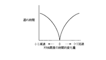
図6は、アクセル開度の時間的変化と制御遅れ時間の関係を示すグラフであり、アクセル開度の時間的変化が「0」の定速状態(アクセル開度は任意)では制御遅れ時間は「0」であり、アクセル開度の時間的変化がプラス側の加速状態、マイナス側の減速状態でともにアクセル開度の時間的変化が大きくなるにしたがい制御遅れ時間を大きくする。
「加速マップ」「減速マップ」「定速マップ」はこれらの関係に基づいて、予め作成される。
【0036】
ステップS105,107,109の処理を実行した後、ステップS110に進み、セル電圧検出装置15によって検出された各セル電圧から平均セル電圧を算出し、この平均セル電圧に基づいて計算あるいは放熱量マップにより燃料電池スタック1の放熱量を算出する。
次に、ステップS111に進み、ステップS105,107,109で算出された必要水蒸気流量が得られる露点(以下、必要露点という)を算出し、必要露点が得られる冷却水出口温度(目標冷却水出口温度という)を算出する。
【0037】
次に、ステップS112に進み、冷却水入口温度センサ13で検出された冷却水入口温度と、ステップS111で算出した目標冷却水出口温度との温度差(以下、目標冷却水温度差という)を算出する。
次に、ステップS113に進み、ステップS110で算出した燃料電池スタック1の放熱量と、ステップS112で算出した目標冷却水温度差から、冷却水ポンプ9の目標流量を算出し、さらに、ステップS114に進んで、この目標流量に対応する冷却水ポンプ9の目標回転数NWPBASEを算出する。
【0038】
次に、冷却水ポンプ9の回転数のフィードバック制御を図3のフローチャートに従って説明する。
まず、ステップS201において、冷却水入口温度センサ13と冷却水出口温度センサ14で検出された冷却水入口温度と冷却水出口温度から、現状の冷却水温度差を算出し、この現状の冷却水温度差とステップS112で算出した目標冷却水温度差との差、すなわち、冷却水温度差のずれ量(TWER)を算出する。
【0039】
次に、ステップS202に進み、前回の冷却水温度差のずれ量(TWERN1)と今回の冷却水温度差のずれ量(TWER)の差、換言すれば、前回と今回の目標冷却水温度差に対するずれ量の差(TWDER)を算出する。
次に、ステップS203において、今回の冷却水温度差のずれ量(TWER)に比例項係数(P項係数)KPNWPを乗じて、比例項(P項)NKPERを算出する。
【0040】
次に、ステップS204に進み、今回の冷却水温度差のずれ量(TWER)に積分項係数(I項係数)KINWPを乗じ、さらに、前回の積分項(I項)NKIERN1を加算して、積分項NKIERを算出する。
次に、ステップS205に進み、ステップS202で算出した前回と今回の目標冷却水温度差に対するずれ量の差TWDERに、微分項係数(D項係数)KDNWPを乗じて、微分項(D項)NKDERを算出する。
【0041】
次に、ステップS206に進み、ステップS203で算出した比例項NKPERと、ステップS204で算出した積分項NKIERと、ステップS205で算出した微分項NKDERを加算してフィードバック量NWPFBを算出する。
次に、ステップS207に進み、ステップS114で算出した冷却水ポンプ9の目標回転数NWPBASEに、ステップS206で算出したフィードバック量NWPFBを乗じて、冷却水ポンプ9の要求回転数NWPCMDを算出して、本ルーチンの実行を一旦終了する。
【0042】
そして、車両が定速状態(ステップS108)のときには直ちに冷却水ポンプ9の目標回転数NWPBASEを変更して、ステップS201〜S207に従い冷却水ポンプ9のフィードバック制御を実行し、一方、車両が加速状態(ステップS104)あるいは減速状態(ステップS106)のときには、ステップS105あるいはステップS107で算出した遅れ時間が経過した後に冷却水ポンプ9の目標回転数NWPBASEを変更して、ステップS201〜S207に従い冷却水ポンプ9のフィードバック制御を実行する。
【0043】
以上のように、この実施の形態の燃料電池システムによれば、バイパス流路や特別な機器、配管などを設けなくても、冷却水流量を制御して冷却水出口温度を制御するだけで燃料電池スタック1に供給される空気を最適な湿度に制御することができ、燃料電池スタック1に流入する加湿水蒸気量を発電に最適に制御することができるので、燃料電池スタック1の発電状態を良好に保持し、発電効率を向上させることができるだけでなく、システム構成が簡単になり、システムの小型・軽量化、コストダウンを図ることができる。
【0044】
また、車両の加速時および減速時には冷却水ポンプ9の制御に遅れ時間を設けているので、加速時における加湿遅れや、減速時における燃料電池スタック内の生成水排除不良を未然に防止することができ、過渡状態においても燃料電池スタック1の発電状態を安定させ、電圧を安定することができる。
【0045】
なお、この実施の形態においては、冷却水入口温度センサ13により冷媒入口温度検出手段が実現され、、図2に示す加湿量制御におけるステップS105,S107,S109によって必要水蒸気流量算出手段および遅れ時間設定手段が実現され、ステップS110により放熱量算出手段が実現され、ステップS111により目標冷媒出口温度算出手段が実現され、ステップS113により冷媒流量算出手段が実現され、図3に示す冷却水ポンプ回転数制御におけるステップS201〜S207により冷媒流量制御手段が実現される。
【0046】
〔他の実施の形態〕
尚、この発明は前述した実施の形態に限られるものではない。
例えば、燃料電池システムは燃料電池車両に搭載されるものに限られない。また、水回収循環手段は中空糸加湿器に限られるものではなく、平状あるいは波状の水蒸気透過膜を用いた加湿器であってもよい。
【0047】
【発明の効果】
以上説明するように、請求項1に記載した発明によれば、バイパス流路等の特別な機器類を設けないで、酸化剤ガスに対する加湿量の最適制御ができて、燃料電池スタックに流入する加湿水蒸気量の最適制御ができるので、システム構成の複雑化や大型化、及びそれに伴うコストアップなどを招くことなく、燃料電池スタックの発電状態を良好に保ち発電効率の向上を図ることができるという優れた効果が奏される。
【0048】
請求項2に記載した発明によれば、燃料電池スタックの負荷増大時における加湿遅れや、負荷減少時における燃料電池スタック内の生成水排除不良を未然に防止することが可能になるので、燃料電池スタックの発電状態の安定化、すなわち、電圧の安定化を図ることができる。
【0049】
請求項3に記載した発明によれば、バイパス流路等の特別な機器類を設けないで、酸化剤ガスに対する加湿量の最適制御ができて、燃料電池スタックに流入する加湿水蒸気量の最適制御ができるので、システム構成の複雑化や大型化、及びそれに伴うコストアップなどを招くことなく、燃料電池スタックの発電状態を良好に保ち発電効率の向上を図ることができるという優れた効果が奏される。
【0050】
請求項4に記載した発明によれば、燃料電池スタックの負荷増大時における加湿遅れや、負荷減少時における燃料電池スタック内の生成水排除不良を未然に防止することが可能になるので、燃料電池スタックの発電状態の安定化、すなわち、電圧の安定化を図ることができる。
【図面の簡単な説明】
【図1】 この発明に係る燃料電池システムの一実施の形態における概略構成図である。
【図2】 前記実施の形態における加湿量制御のフローチャートである。
【図3】 前記実施の形態における冷却水ポンプ回転数制御のフローチャートである。
【図4】 燃料電池の負荷の大きさに対する必要空気量および必要加湿量の関係を示したグラフである。
【図5】 定速時と加速時と減速時における必要水蒸気量の相対関係を示す模式的グラフである。
【図6】 アクセル開度の時間的変化と制御遅れ時間の関係を示すグラフである。
【図7】 本発明の加湿量制御原理を説明するための図である。
【図8】 冷媒出口温度と酸化剤オフガス出口温度との関係を示すグラフである。
【図9】 車両の加速時における冷媒流量制御例を示す図である。
【図10】 車両の減速時における冷媒流量制御例を示す図である。
【符号の説明】
1 燃料電池スタック
2 エアコンプレッサ(酸化剤ガス供給手段)
3 加湿器(水回収循環手段)
5 水素供給装置(燃料ガス供給手段)
9 冷却水ポンプ(冷媒供給手段)
13 冷却水入口温度センサ(冷媒入口温度検出手段)
ステップS105,S107,S109 必要水蒸気流量算出手段、遅れ時間設定手段
ステップS110 放熱量算出手段
ステップS111 目標冷媒出口温度算出手段
ステップS113 冷媒流量算出手段
ステップS201〜S207 冷媒流量制御手段[0001]
BACKGROUND OF THE INVENTION
The present invention relates to humidification control for an oxidant gas in a fuel cell system.
[0002]
[Prior art]
Some fuel cell systems installed in fuel cell vehicles include a fuel cell stack in which a plurality of single cells each provided with an anode and a cathode on both sides of a solid polymer electrolyte membrane are stacked via a separator. In this fuel cell stack, when a fuel gas (for example, hydrogen gas) is supplied to the anode and an oxidant gas (for example, oxygen or air) is supplied to the cathode, the hydrogen gas is ionized at the anode and moves through the solid polymer electrolyte. , The electrons can move through an external load to the cathode and extract electrical energy from a series of electrochemical reactions that react with oxygen to produce water. Since water is generated on the cathode side in this way, the unreacted oxidant gas (hereinafter referred to as oxidant off-gas) discharged from the fuel cell has a high water content.
[0003]
In addition, the fuel cell stack generates heat when generating power, but since the fuel cell has an operating temperature range, it is necessary to cool the fuel cell so that the fuel cell does not rise above the upper limit temperature. Therefore, a cooling flow path is provided in the fuel cell stack, and a coolant is passed through the cooling flow path to remove heat and cool the fuel cell.
[0004]
By the way, in the fuel cell stack, when the solid polymer electrolyte membrane is dried, the ionic conductivity is lowered and the energy conversion efficiency is lowered. It is necessary to supply moisture to the polymer electrolyte membrane.
For this reason, in this type of fuel cell stack, a fuel gas or an oxidant gas is humidified in advance by a humidifier before being supplied to the fuel cell, and the humidified gas is supplied to the solid polymer electrolyte membrane, thereby providing a solid state. Water is supplied to the polymer electrolyte membrane.
[0005]
As one of the humidifiers that humidify the oxidant gas, the oxidant gas and the oxidant off-gas flow through the water vapor permeable membrane, and the moisture in the oxidant off gas is delivered to the oxidant gas through the water vapor permeable film. In other words, a humidifier has been proposed in which moisture is collected from the oxidant off-gas and this moisture is circulated to the oxidant gas (see, for example, Patent Document 1). However, in this humidifier, it is difficult to control the amount of humidification, and the degree of humidification with respect to the oxidant gas has to become a matter of course. As a result, the oxidant off-gas is cooled in the humidifier and the moisture in the oxidant off-gas is condensed, so that the humidification amount for the oxidant gas is insufficient, and conversely, the humidification amount for the oxidant gas becomes excessive. Flooding occurred in the fuel cell stack, resulting in problems such as a decrease in power generation capacity.
[0006]
In order to solve this problem, fuel cell systems disclosed in Patent Document 2,
In the fuel cell system disclosed in Patent Document 2, a bypass flow path that allows the oxidant off gas to flow by bypassing the humidifier, and whether the oxidant off gas flows to the humidifier or the bypass flow path A switching valve is provided to control the flow path of the oxidant off gas by switching the switching valve, and control the humidification amount for the oxidant gas by flowing the oxidant off gas to the humidifier or bypassing the humidifier. is doing.
[0007]
Further, in the fuel cell system disclosed in
[0008]
Furthermore, the fuel cell system disclosed in Patent Document 4 includes a heating flow path for flowing the refrigerant that has left the fuel cell stack around the humidifier, and cooling the fuel cell stack by flowing the refrigerant through the heating flow path. Thus, the humidifier is heated by the refrigerant whose temperature has been increased, and the temperature of the oxidant off-gas in the humidifier is prevented from lowering, thereby preventing the moisture in the oxidant off-gas from condensing and humidifying the oxidant gas. The amount is prevented from decreasing.
[0009]
[Patent Document 1]
JP-A-6-132038
[Patent Document 2]
JP 2000-164231 A,
[Patent Document 3]
JP 2001-216984 A,
[Patent Document 4]
JP 2001-216981 A
[0010]
[Problems to be solved by the invention]
However, in the conventional fuel cell systems disclosed in these patent documents, although the humidification amount can be controlled, devices such as a bypass channel, a switching valve, a flow rate control valve, a heating channel, and the like are connected. Since piping is required, the number of parts is increased, the system is increased in size, and the cost is increased.
Accordingly, the present invention provides a fuel cell system capable of controlling the amount of humidification for an oxidant gas with a simple configuration.
[0011]
[Means for Solving the Problems]
In order to solve the above-mentioned problem, the invention described in
[0012]
By configuring in this way, it becomes possible to control the oxidant gas to an optimal humidification amount without providing special equipment such as a bypass channel, and to optimize the amount of humidified water vapor flowing into the fuel cell stack. It becomes possible to control.
[0013]
The invention described in claim 2 is characterized in that, in the invention described in
By configuring in this way, it becomes possible to prevent the humidification delay when the load of the fuel cell stack is increased and the generated water removal failure in the fuel cell stack when the load is decreased. For example, in the case of a fuel cell stack for driving a fuel cell vehicle, the load fluctuation of the fuel cell stack corresponds to acceleration or deceleration, the speed of the load fluctuation corresponds to acceleration or deceleration, and constant speed running is Corresponds to no load fluctuation.
[0014]
The invention described in
[0015]
With this configuration, it is possible to control so that the heat dissipation amount calculated by the heat dissipation amount calculation unit and the heat amount received from the fuel cell stack when the refrigerant cools the fuel cell stack are the same. Further, since the refrigerant outlet temperature and the oxidant off-gas outlet temperature are in a substantially proportional relationship, the oxidant gas can be controlled to the optimum humidification amount only by controlling the refrigerant flow rate by the refrigerant flow rate control means. It becomes possible to optimally control the amount of humidified water vapor flowing into the battery stack. Moreover, special equipment such as a bypass flow path is not required.
[0016]
According to a fourth aspect of the present invention, in the third aspect of the present invention, a delay time is set in the flow rate control start to the target refrigerant flow rate by the refrigerant flow rate control means in accordance with the load fluctuation speed of the fuel cell stack. Delay time setting means (for example, steps S105, S107, and S109 in the embodiments described later).
By configuring in this way, it becomes possible to prevent the humidification delay when the load of the fuel cell stack is increased and the generated water removal failure in the fuel cell stack when the load is decreased. For example, in the case of a fuel cell stack for driving a fuel cell vehicle, the load variation of the fuel cell stack corresponds to acceleration or deceleration, the load increase corresponds to acceleration, the load decrease corresponds to deceleration, Constant speed driving is supported without load fluctuations.
[0017]
DETAILED DESCRIPTION OF THE INVENTION
An embodiment of a fuel cell system according to the present invention will be described below with reference to the drawings of FIGS.
A fuel cell system according to the present invention recovers moisture from an oxidant gas off-gas (hereinafter referred to as oxidant off-gas) discharged from a cathode of a fuel cell stack, and the recovered moisture is supplied to the cathode as an oxidant gas. Is equipped with a humidifier (water recovery and circulation means) to control the amount of humidification for the oxidant gas by controlling the flow rate of the refrigerant that cools the fuel cell stack. The principle will be described with reference to FIGS. In this explanation of the principle, “fuel cell” is synonymous with fuel cell stack.
[0018]
As shown in FIG. 7, in a fuel cell system that cools heat generated by power generation in a fuel cell with a refrigerant (for example, cooling water) flowing in the fuel cell, the temperature in the fuel cell is the temperature of the refrigerant having a large heat capacity. The refrigerant outlet temperature is highly dependent on the refrigerant flow rate.
Here, the heat balance in the fuel cell is as follows.
The calorific value Q accompanying power generation in the fuel cell can be obtained from the following equation (1).
Q = I × (V0−V) × n (1) Formula
Here, I is a current, V0 is a calorific value reference voltage, V is a cell voltage, and n is the number of cells.
[0019]
The amount of heat Qc received by the refrigerant that cools the fuel cell can be obtained from the following equation (2).
Qc = Fc × ρ × c × (Tc2−Tc1) (2) Formula
Here, Fc is the refrigerant flow rate, ρ is the density of the refrigerant, c is the specific heat of the refrigerant, Tc2 is the refrigerant outlet temperature, and Tc1 is the refrigerant inlet temperature.
Further, the humidified water vapor amount Fv obtained by the humidifier can be obtained from the following equation (3).
Fv = c1 × f (Tg2) (3)
Here, Tg2 is the temperature of the oxidant offgas discharged from the fuel cell (hereinafter referred to as oxidant offgas outlet temperature), and c1 is a coefficient.
[0020]
By the way, in this fuel cell system, it has been experimentally found that the oxidant off-gas outlet temperature Tg2 and the refrigerant outlet temperature Tc2 are substantially proportional. FIG. 8 shows an example of the experimental result. From this experimental result, it can be seen that the refrigerant outlet temperature Tc2 is closer to the proportional relationship of the oxidant off-gas outlet temperature Tg2 than the fuel gas (hydrogen gas) outlet temperature Th2.
Therefore, from equations (1), (2), and (3), the refrigerant outlet temperature Tc2 and the oxidant offgas outlet temperature Tg2 are controlled by the refrigerant flow rate Fc, and the amount of humidified water vapor flowing into the fuel cell can be controlled. It becomes.
[0021]
Further, the required water amount Fr according to the load of the fuel cell can be obtained from the following equation (4).
Fr = Fgin × {Pwin (Tdin) / (Pgin−Pwin (Tdin))} (4)
Here, Fgin [NLM] is an inlet gas flow rate (dry reference) at a certain load, Tdin [° C.] is a necessary inlet gas dew point, Pgin [Pa abs] is an inlet gas pressure (wet reference), and Pwin (Tdin) [Pa ] Is the water vapor partial pressure at the dew point Tdin. In the fuel cell vehicle, the load of the fuel cell corresponds to the accelerator opening.
[0022]
Therefore, by monitoring the refrigerant inlet temperature Tc1 and controlling the refrigerant outlet temperature Tc2 so that Fv = Fr, the oxidant gas can be controlled to the optimum humidified state, and therefore the refrigerant outlet temperature Tc2 If the refrigerant flow rate is controlled so as to satisfy the above, it becomes possible to control the oxidant gas to an optimum humidified state. This is the principle of the humidification control of the fuel cell in the present invention.
[0023]
Further, in a fuel cell for driving a vehicle (fuel cell stack), there is a possibility that a delay in humidification will occur with respect to load fluctuations during acceleration, and the voltage of the fuel cell may decrease. Therefore, in the present invention, as shown in FIG. The refrigerant flow rate is not increased immediately during acceleration, but the refrigerant flow rate is decreased (including maintaining the current status) for a predetermined time from the start of acceleration, thereby increasing the refrigerant outlet temperature and increasing the humidification amount, thereby preventing the humidification delay. In order to prevent the voltage drop of the fuel cell. Then, humidification control is performed according to the degree of acceleration after the predetermined time has elapsed.
[0024]
On the other hand, in a fuel cell for driving a vehicle (fuel cell stack), when the flow rate of the reaction gas decreases at the time of deceleration, the generated water generated in the fuel cell cannot be removed, and flooding may occur, resulting in unstable voltage. Therefore, in the present invention, as shown in FIG. 10, the refrigerant flow rate is not reduced immediately at the time of deceleration, and the refrigerant flow rate is not changed for a predetermined time from the start of deceleration, thereby lowering the refrigerant outlet temperature and reducing the humidification amount. Thus, the amount of generated water is reduced, and the voltage is stabilized.
[0025]
Next, the fuel cell system according to the present invention will be described in detail with reference to FIGS. This embodiment is an aspect applied to a fuel cell system mounted on a fuel cell vehicle.
FIG. 1 is a schematic configuration diagram of a fuel cell system. The
[0026]
The
[0027]
The outside air is pressurized by an air compressor (oxidant gas supply means) 2, humidified by a cathode humidifier (water recovery and circulation means) 3, and supplied to the cathode of the
[0028]
The
[0029]
On the other hand, the hydrogen gas released from the hydrogen supply device (fuel gas supply means) 5 such as a high-pressure hydrogen tank is decompressed by the fuel supply control valve 6, passes through the
[0030]
Further, the coolant for cooling the
[0031]
The fuel cell system also detects an air temperature sensor 11 and an
[0032]
Next, humidification amount control in this fuel cell system will be described with reference to the flowchart of FIG.
First, in step S101, the
Next, it progresses to step S102, the air flow rate of the
[0033]
Next, the process proceeds to step S103, where the temporal change in the accelerator opening detected by the
When it is determined in step S103 that the vehicle is in the “acceleration state” (step S104), the process proceeds to step S105, and the mass flow rate of air and the degree of acceleration (plus acceleration magnitude) are referred to the “acceleration map”. The required water vapor flow rate according to the above and the control delay time of the cooling water pump 9 are calculated.
[0034]
When it is determined in step S103 that the vehicle is in the “deceleration state” (step S106), the process proceeds to step S107, and the “deceleration map” is referenced to refer to the air mass flow rate and the degree of deceleration (the magnitude of negative acceleration). The required water vapor flow rate according to the above and the control delay time of the cooling water pump 9 are calculated.
Further, when it is determined in step S103 that the state is “constant speed state” (step S108), the process proceeds to step S109, and referring to the “constant speed map”, the required water vapor flow rate corresponding to the mass flow rate of air is determined. calculate. In this “constant speed state”, since there is no delay time in the control of the cooling water pump 9, the control delay time is not calculated.
[0035]
Here, FIG. 4 is a graph showing the relationship between the required air amount and the required humidification amount with respect to the magnitude of the load (that is, the accelerator opening) of the fuel cell, and the required air amount and the required humidification amount are increased as the load increases. Need to increase.
FIG. 5 is a schematic graph showing a relative relationship between the required water vapor amount at constant speed, acceleration and deceleration, and requires a larger amount of water vapor than at constant speed during acceleration, and at constant speed during deceleration. The amount of water vapor may be less than that.
FIG. 6 is a graph showing the relationship between the time variation of the accelerator opening and the control delay time. In the constant speed state where the time change of the accelerator opening is “0” (the accelerator opening is arbitrary), the control delay time is It is “0”, and the control delay time is increased as the time change of the accelerator opening increases in both the positive acceleration state and the negative deceleration state.
The “acceleration map”, “deceleration map”, and “constant speed map” are created in advance based on these relationships.
[0036]
After executing the processing of steps S105, 107, and 109, the process proceeds to step S110, where an average cell voltage is calculated from each cell voltage detected by the cell
Next, the process proceeds to step S111, a dew point (hereinafter referred to as a necessary dew point) at which the required water vapor flow rate calculated in steps S105, 107, and 109 is obtained is calculated, and a cooling water outlet temperature (target cooling water outlet) at which the necessary dew point is obtained. Temperature).
[0037]
Next, the process proceeds to step S112, and a temperature difference between the cooling water inlet temperature detected by the cooling water inlet temperature sensor 13 and the target cooling water outlet temperature calculated in step S111 (hereinafter referred to as a target cooling water temperature difference) is calculated. To do.
Next, proceeding to step S113, the target flow rate of the cooling water pump 9 is calculated from the heat radiation amount of the
[0038]
Next, feedback control of the rotational speed of the cooling water pump 9 will be described with reference to the flowchart of FIG.
First, in step S201, the current cooling water temperature difference is calculated from the cooling water inlet temperature and the cooling water outlet temperature detected by the cooling water inlet temperature sensor 13 and the cooling water
[0039]
Next, the process proceeds to step S202, where the difference between the previous cooling water temperature difference deviation (TWERN1) and the current cooling water temperature difference deviation (TWER), in other words, the difference between the previous and current target cooling water temperature difference. A difference in deviation (TWDER) is calculated.
Next, in step S203, a proportional term (P term) NKPER is calculated by multiplying the deviation amount (TWER) of the current cooling water temperature difference by a proportional term coefficient (P term coefficient) KPNWP.
[0040]
Next, the process proceeds to step S204, where the current deviation amount (TWER) of the cooling water temperature difference is multiplied by an integral term coefficient (I term coefficient) KINWP, and the previous integral term (I term) NKIERN1 is added to integrate. The term NKIER is calculated.
Next, proceeding to step S205, the differential term coefficient (D term coefficient) KDNWP is multiplied by the difference TWDER of the deviation amount with respect to the previous and current target cooling water temperature difference calculated at step S202, and the differential term (D term) NKDER. Is calculated.
[0041]
In step S206, the proportional term NKPER calculated in step S203, the integral term NKIER calculated in step S204, and the differential term NKDER calculated in step S205 are added to calculate the feedback amount NWPFB.
Next, the process proceeds to step S207, where the target rotational speed NWPBASE of the cooling water pump 9 calculated in step S114 is multiplied by the feedback amount NWPFB calculated in step S206 to calculate the required rotational speed NWPCMD of the cooling water pump 9. The execution of this routine is temporarily terminated.
[0042]
When the vehicle is in a constant speed state (step S108), the target rotational speed NWPBASE of the cooling water pump 9 is immediately changed, and the feedback control of the cooling water pump 9 is executed according to steps S201 to S207, while the vehicle is in the acceleration state. In step S104 or in a deceleration state (step S106), the target rotational speed NWPBASE of the cooling water pump 9 is changed after the delay time calculated in step S105 or step S107 has elapsed, and the cooling water pump is changed according to steps S201 to S207. 9 feedback control is executed.
[0043]
As described above, according to the fuel cell system of this embodiment, the fuel flow rate can be controlled by controlling the coolant flow rate and controlling the coolant outlet temperature without providing a bypass channel, special equipment, piping, or the like. The air supplied to the
[0044]
In addition, since a delay time is provided in the control of the cooling water pump 9 when the vehicle is accelerated and decelerated, it is possible to prevent a delay in humidification during acceleration and a failure to eliminate generated water in the fuel cell stack during deceleration. Even in a transient state, the power generation state of the
[0045]
In this embodiment, the coolant inlet temperature detection means is realized by the cooling water inlet temperature sensor 13, and the necessary water vapor flow rate calculating means and the delay time setting are performed by steps S105, S107, and S109 in the humidification amount control shown in FIG. Step S110 realizes a heat release amount calculation means, Step S111 realizes a target refrigerant outlet temperature calculation means, Step S113 realizes a refrigerant flow rate calculation means, and cooling water pump rotation speed control shown in FIG. The refrigerant flow rate control means is realized by steps S201 to S207.
[0046]
[Other Embodiments]
The present invention is not limited to the embodiment described above.
For example, the fuel cell system is not limited to the one mounted on the fuel cell vehicle. The water recovery / circulation means is not limited to the hollow fiber humidifier, and may be a humidifier using a flat or wavy water vapor permeable membrane.
[0047]
【The invention's effect】
As described above, according to the first aspect of the invention, it is possible to optimally control the humidification amount with respect to the oxidant gas without providing special equipment such as a bypass flow path, and to flow into the fuel cell stack. Optimal control of the amount of humidified water vapor can be achieved, so that the power generation state of the fuel cell stack can be maintained well and the power generation efficiency can be improved without complicating or increasing the size of the system configuration and the associated cost increase. Excellent effect is achieved.
[0048]
According to the second aspect of the present invention, it is possible to prevent the delay in humidification when the load of the fuel cell stack is increased and the failure to eliminate the generated water in the fuel cell stack when the load is decreased. The power generation state of the stack can be stabilized, that is, the voltage can be stabilized.
[0049]
According to the third aspect of the present invention, the optimum control of the humidification amount with respect to the oxidant gas can be performed without providing special equipment such as a bypass flow path, and the optimum control of the humidified water vapor amount flowing into the fuel cell stack. As a result, the power generation state of the fuel cell stack can be maintained well and the power generation efficiency can be improved without complicating or increasing the size of the system configuration and the associated cost increase. The
[0050]
According to the fourth aspect of the present invention, it is possible to prevent a delay in humidification when the load of the fuel cell stack is increased and a failure to eliminate generated water in the fuel cell stack when the load is decreased. The power generation state of the stack can be stabilized, that is, the voltage can be stabilized.
[Brief description of the drawings]
FIG. 1 is a schematic configuration diagram of an embodiment of a fuel cell system according to the present invention.
FIG. 2 is a flowchart of humidification amount control in the embodiment.
FIG. 3 is a flowchart of cooling water pump rotation speed control in the embodiment.
FIG. 4 is a graph showing the relationship between the required air amount and the required humidification amount with respect to the load size of the fuel cell.
FIG. 5 is a schematic graph showing a relative relationship between required water vapor amounts at constant speed, acceleration and deceleration.
FIG. 6 is a graph showing the relationship between the time variation of the accelerator opening and the control delay time.
FIG. 7 is a diagram for explaining the humidification amount control principle of the present invention.
FIG. 8 is a graph showing the relationship between the refrigerant outlet temperature and the oxidant off-gas outlet temperature.
FIG. 9 is a diagram illustrating an example of refrigerant flow rate control during vehicle acceleration.
FIG. 10 is a diagram illustrating an example of refrigerant flow rate control during vehicle deceleration.
[Explanation of symbols]
1 Fuel cell stack
2 Air compressor (oxidant gas supply means)
3 humidifier (water recovery and circulation means)
5 Hydrogen supply device (fuel gas supply means)
9 Cooling water pump (refrigerant supply means)
13 Cooling water inlet temperature sensor (refrigerant inlet temperature detecting means)
Steps S105, S107, S109 Required water vapor flow rate calculating means, delay time setting means
Step S110: heat dissipation amount calculation means
Step S111: Target refrigerant outlet temperature calculation means
Step S113: Refrigerant flow rate calculation means
Steps S201 to S207 Refrigerant flow rate control means
Claims (4)
該燃料電池スタックに設けられた冷却流路に冷媒を供給する冷媒供給手段と、
前記燃料電池スタックのアノードに燃料ガスを供給する燃料ガス供給手段と、
前記燃料電池スタックのカソードに酸化剤ガスを供給する酸化剤ガス供給手段と、
前記カソードに供給される酸化剤ガスと前記カソードから排出された酸化剤オフガスとを水分透過膜を隔てて流通させ前記酸化剤オフガス中の水分を前記酸化剤ガスに回収する水回収循環手段と、
を備えた燃料電池システムにおいて、
酸化剤ガス流量が多いほど必要水蒸気流量が多くなるように設定されたマップを参照して前記燃料電池スタックに供給される前記酸化剤ガスの流量に応じた必要水蒸気流量を算出する必要水蒸気流量算出手段と、
前記必要水蒸気流量算出手段で算出された必要水蒸気流量を得るために必要な燃料電池スタック出口の目標冷媒温度を算出する目標冷媒出口温度算出手段と、
を備え、前記燃料電池スタックの出口における冷媒温度が前記目標冷媒出口温度算出手段により算出された目標冷媒温度となるように前記冷却流路に供給する冷媒の流量を制御して酸化剤オフガス中の水分量を変化させることにより、前記燃料電池スタックに供給される酸化剤ガスの水分量を制御することを特徴とする燃料電池システム。A fuel cell stack in which a plurality of single cells each provided with an anode and a cathode on both sides of a solid polymer electrolyte membrane are stacked via a separator;
Refrigerant supply means for supplying refrigerant to a cooling channel provided in the fuel cell stack;
Fuel gas supply means for supplying fuel gas to the anode of the fuel cell stack;
An oxidant gas supply means for supplying an oxidant gas to the cathode of the fuel cell stack;
Water recovery and circulation means for circulating an oxidant gas supplied to the cathode and an oxidant offgas discharged from the cathode across a moisture permeable membrane and recovering moisture in the oxidant offgas to the oxidant gas ;
In a fuel cell system comprising:
The required water vapor flow rate calculation for calculating the required water vapor flow rate according to the flow rate of the oxidant gas supplied to the fuel cell stack with reference to the map set so that the required water vapor flow rate increases as the oxidant gas flow rate increases. Means,
Target refrigerant outlet temperature calculating means for calculating a target refrigerant temperature at the outlet of the fuel cell stack necessary for obtaining the required water vapor flow rate calculated by the required water vapor flow rate calculating means;
And controlling the flow rate of the refrigerant supplied to the cooling flow path so that the refrigerant temperature at the outlet of the fuel cell stack becomes the target refrigerant temperature calculated by the target refrigerant outlet temperature calculating means . A fuel cell system, wherein the moisture content of the oxidant gas supplied to the fuel cell stack is controlled by changing the moisture content.
該燃料電池スタックに設けられた冷却流路に冷媒を供給する冷媒供給手段と、
前記燃料電池スタックのアノードに燃料ガスを供給する燃料ガス供給手段と、
前記燃料電池スタックのカソードに酸化剤ガスを供給する酸化剤ガス供給手段と、
前記カソードに供給される酸化剤ガスと前記カソードから排出された酸化剤オフガスとを水分透過膜を隔てて流通させ前記酸化剤オフガス中の水分を前記酸化剤ガスに回収する水回収循環手段と、
を備えた燃料電池システムにおいて、
酸化剤ガス流量が多いほど必要水蒸気流量が多くなるように設定されたマップを参照して前記燃料電池スタックに供給される前記酸化剤ガスの流量に応じた必要水蒸気流量を算出する必要水蒸気流量算出手段と、
前記燃料電池スタックのセル電圧を検出するセル電圧検出手段と、
前記セル電圧検出手段により検出されたセル電圧に基づいて前記燃料電池スタックから放出される放熱量を算出する放熱量算出手段と、
前記必要水蒸気流量算出手段で算出された必要水蒸気流量を得るために必要な燃料電池スタック出口の目標冷媒温度を算出する目標冷媒出口温度算出手段と、
前記燃料電池スタック入口の冷媒温度を検出する冷媒入口温度検出手段と、
前記放熱量算出手段により算出された放熱量、および前記冷媒入口温度検出手段で検出された冷媒入口温度と前記目標冷却水出口温度算出手段によって算出された目標冷媒出口温度との温度差に基づいて、前記冷媒が前記冷却流路を流通したときに前記燃料電池スタックから受け取る熱量と前記放熱量とが同じになるように燃料電池スタックに供給すべき目標冷媒流量を算出する冷媒流量算出手段と、
前記燃料電池スタックに前記目標冷媒流量の冷媒が供給されるように前記冷媒供給手段を制御する冷媒流量制御手段と、
を備えることを特徴とする燃料電池システム。A fuel cell stack in which a plurality of single cells each provided with an anode and a cathode on both sides of a solid polymer electrolyte membrane are stacked via a separator;
Refrigerant supply means for supplying refrigerant to a cooling channel provided in the fuel cell stack;
Fuel gas supply means for supplying fuel gas to the anode of the fuel cell stack;
An oxidant gas supply means for supplying an oxidant gas to the cathode of the fuel cell stack;
Water recovery and circulation means for circulating an oxidant gas supplied to the cathode and an oxidant offgas discharged from the cathode across a moisture permeable membrane and recovering moisture in the oxidant offgas to the oxidant gas ;
In a fuel cell system comprising:
The required water vapor flow rate calculation for calculating the required water vapor flow rate according to the flow rate of the oxidant gas supplied to the fuel cell stack with reference to the map set so that the required water vapor flow rate increases as the oxidant gas flow rate increases. Means,
Cell voltage detection means for detecting a cell voltage of the fuel cell stack;
A heat dissipation amount calculating means for calculating a heat dissipation amount released from the fuel cell stack based on a cell voltage detected by the cell voltage detecting means ;
Target refrigerant outlet temperature calculating means for calculating a target refrigerant temperature at the outlet of the fuel cell stack necessary for obtaining the required water vapor flow rate calculated by the required water vapor flow rate calculating means;
A refrigerant inlet temperature detecting means for detecting a refrigerant temperature at the fuel cell stack inlet;
Based on the heat release amount calculated by the heat release amount calculation means and the temperature difference between the refrigerant inlet temperature detected by the refrigerant inlet temperature detection means and the target refrigerant outlet temperature calculated by the target cooling water outlet temperature calculation means. A refrigerant flow rate calculation means for calculating a target refrigerant flow rate to be supplied to the fuel cell stack so that the amount of heat received from the fuel cell stack when the refrigerant flows through the cooling channel and the amount of heat released are the same ;
Refrigerant flow rate control means for controlling the refrigerant supply means so that the fuel cell stack is supplied with the refrigerant having the target refrigerant flow rate;
A fuel cell system comprising:
Priority Applications (1)
| Application Number | Priority Date | Filing Date | Title |
|---|---|---|---|
| JP2002333520A JP3908154B2 (en) | 2001-11-22 | 2002-11-18 | Fuel cell system |
Applications Claiming Priority (3)
| Application Number | Priority Date | Filing Date | Title |
|---|---|---|---|
| JP2001358070 | 2001-11-22 | ||
| JP2001-358070 | 2001-11-22 | ||
| JP2002333520A JP3908154B2 (en) | 2001-11-22 | 2002-11-18 | Fuel cell system |
Publications (2)
| Publication Number | Publication Date |
|---|---|
| JP2003223909A JP2003223909A (en) | 2003-08-08 |
| JP3908154B2 true JP3908154B2 (en) | 2007-04-25 |
Family
ID=27759232
Family Applications (1)
| Application Number | Title | Priority Date | Filing Date |
|---|---|---|---|
| JP2002333520A Expired - Fee Related JP3908154B2 (en) | 2001-11-22 | 2002-11-18 | Fuel cell system |
Country Status (1)
| Country | Link |
|---|---|
| JP (1) | JP3908154B2 (en) |
Families Citing this family (12)
| Publication number | Priority date | Publication date | Assignee | Title |
|---|---|---|---|---|
| JP4677715B2 (en) * | 2003-12-04 | 2011-04-27 | 日産自動車株式会社 | Fuel cell cooling system |
| JP4747498B2 (en) * | 2004-03-08 | 2011-08-17 | 日産自動車株式会社 | Fuel cell system |
| JP4747495B2 (en) * | 2004-03-08 | 2011-08-17 | 日産自動車株式会社 | Fuel cell system |
| JP5076472B2 (en) | 2006-12-05 | 2012-11-21 | トヨタ自動車株式会社 | Fuel cell system |
| WO2009060706A1 (en) * | 2007-11-08 | 2009-05-14 | Toyota Jidosha Kabushiki Kaisha | Fuel cell system |
| JP2009123472A (en) * | 2007-11-14 | 2009-06-04 | Honda Motor Co Ltd | Operation method of fuel cell and fuel cell system |
| JP5380932B2 (en) * | 2008-07-17 | 2014-01-08 | トヨタ自動車株式会社 | Fuel cell system |
| JP5463704B2 (en) * | 2009-03-18 | 2014-04-09 | 富士電機株式会社 | Phosphoric acid freeze prevention method and phosphoric acid freeze prevention device for phosphoric acid fuel cell |
| JP5585412B2 (en) * | 2010-11-19 | 2014-09-10 | 日産自動車株式会社 | Fuel cell system |
| CN108613013B (en) * | 2018-05-19 | 2020-10-13 | 大连理工大学 | Hydrogen supply system of vehicle-mounted hydrogen storage cylinder and working method thereof |
| WO2021229814A1 (en) * | 2020-05-15 | 2021-11-18 | 日産自動車株式会社 | Fuel battery stack |
| JP7347328B2 (en) * | 2020-05-27 | 2023-09-20 | トヨタ自動車株式会社 | fuel cell system |
-
2002
- 2002-11-18 JP JP2002333520A patent/JP3908154B2/en not_active Expired - Fee Related
Also Published As
| Publication number | Publication date |
|---|---|
| JP2003223909A (en) | 2003-08-08 |
Similar Documents
| Publication | Publication Date | Title |
|---|---|---|
| US8216736B2 (en) | Fuel cell system using evaporative cooling method | |
| JP4830852B2 (en) | Fuel cell system | |
| JP3908154B2 (en) | Fuel cell system | |
| US7655330B2 (en) | Method of operating fuel cell and power supply system | |
| JP2011029158A (en) | Fuel cell system | |
| JP2004165058A (en) | Control device of fuel cell system | |
| US7323262B2 (en) | Method of operating a fuel cell power system to deliver constant power | |
| JP3832271B2 (en) | Fuel cell system | |
| JP4144321B2 (en) | Fuel cell system | |
| JP4946087B2 (en) | Fuel cell system | |
| JP2007242449A (en) | Fuel cell system | |
| JP4744058B2 (en) | Fuel cell system | |
| JP2002141094A (en) | Fuel cell system | |
| JP4288721B2 (en) | Fuel cell system | |
| JP2000106206A (en) | Fuel cell system | |
| JP2004165087A (en) | Controlling device of fuel cell stack | |
| JP4672120B2 (en) | Fuel cell device and method of operating fuel cell device. | |
| JP5109284B2 (en) | Fuel cell system | |
| JP5310739B2 (en) | Fuel cell system | |
| JP2009245818A (en) | Fuel cell device | |
| JP2005050639A (en) | Fuel cell system | |
| JP2010192292A (en) | Fuel cell system and method for operating the same | |
| JP2008004431A (en) | Fuel cell system | |
| JP4000971B2 (en) | Fuel cell system | |
| JP2006032094A (en) | Fuel cell system |
Legal Events
| Date | Code | Title | Description |
|---|---|---|---|
| A621 | Written request for application examination |
Free format text: JAPANESE INTERMEDIATE CODE: A621 Effective date: 20041130 |
|
| A977 | Report on retrieval |
Free format text: JAPANESE INTERMEDIATE CODE: A971007 Effective date: 20061002 |
|
| A131 | Notification of reasons for refusal |
Free format text: JAPANESE INTERMEDIATE CODE: A131 Effective date: 20061017 |
|
| A521 | Written amendment |
Free format text: JAPANESE INTERMEDIATE CODE: A523 Effective date: 20061212 |
|
| TRDD | Decision of grant or rejection written | ||
| A01 | Written decision to grant a patent or to grant a registration (utility model) |
Free format text: JAPANESE INTERMEDIATE CODE: A01 Effective date: 20070109 |
|
| A61 | First payment of annual fees (during grant procedure) |
Free format text: JAPANESE INTERMEDIATE CODE: A61 Effective date: 20070117 |
|
| R150 | Certificate of patent or registration of utility model |
Free format text: JAPANESE INTERMEDIATE CODE: R150 |
|
| FPAY | Renewal fee payment (event date is renewal date of database) |
Free format text: PAYMENT UNTIL: 20100126 Year of fee payment: 3 |
|
| FPAY | Renewal fee payment (event date is renewal date of database) |
Free format text: PAYMENT UNTIL: 20110126 Year of fee payment: 4 |
|
| FPAY | Renewal fee payment (event date is renewal date of database) |
Free format text: PAYMENT UNTIL: 20110126 Year of fee payment: 4 |
|
| FPAY | Renewal fee payment (event date is renewal date of database) |
Free format text: PAYMENT UNTIL: 20120126 Year of fee payment: 5 |
|
| FPAY | Renewal fee payment (event date is renewal date of database) |
Free format text: PAYMENT UNTIL: 20120126 Year of fee payment: 5 |
|
| FPAY | Renewal fee payment (event date is renewal date of database) |
Free format text: PAYMENT UNTIL: 20130126 Year of fee payment: 6 |
|
| FPAY | Renewal fee payment (event date is renewal date of database) |
Free format text: PAYMENT UNTIL: 20130126 Year of fee payment: 6 |
|
| FPAY | Renewal fee payment (event date is renewal date of database) |
Free format text: PAYMENT UNTIL: 20140126 Year of fee payment: 7 |
|
| LAPS | Cancellation because of no payment of annual fees |