JP3907663B2 - Thin display device - Google Patents
Thin display device Download PDFInfo
- Publication number
- JP3907663B2 JP3907663B2 JP2005007355A JP2005007355A JP3907663B2 JP 3907663 B2 JP3907663 B2 JP 3907663B2 JP 2005007355 A JP2005007355 A JP 2005007355A JP 2005007355 A JP2005007355 A JP 2005007355A JP 3907663 B2 JP3907663 B2 JP 3907663B2
- Authority
- JP
- Japan
- Prior art keywords
- stand
- display device
- display
- column
- connecting portion
- Prior art date
- Legal status (The legal status is an assumption and is not a legal conclusion. Google has not performed a legal analysis and makes no representation as to the accuracy of the status listed.)
- Expired - Fee Related
Links
Images


Description
本発明は、種々の使用形態に用いることのできる薄型の表示装置及び表示部の抜脱方法に関する。 The present invention relates to a thin display device that can be used in various usage forms and a method for removing a display portion.
従来のブラウン管を使用するテレビでは、そのテレビ表示画面がテレビを見る人の目線の高さや向きと合致するように所定高さに維持されるために、そのテレビの重さに耐え得るテレビ載置用のラックやケース等の上に置かれて利用されていた。 In a conventional television using a cathode ray tube, the television display screen is maintained at a predetermined height so as to match the height and orientation of the viewer's eyes, so that the television can withstand the weight of the television. It was placed on a rack or case for use.
一方、最近ではブラウン管に代わって液晶ディスプレイやプラズマディスプレイなどを用いた薄型テレビが普及している。ブラウン管テレビの場合には、その重量が重いため、見易さを考慮してそれを所定高さに維持するためには頑丈なテレビ載置用のラック、ケース、台等が必要であったが、薄型テレビでは薄型化に伴って軽量化も実現されているため、従来のテレビ載置用のラック、ケース、台等に代わって、例えば蛍光灯スタンドを支えるスタンドのように薄型テレビを脚状に支えるスタンドにて代用でき、それにより設置面積も少なくできる利点を有していた(従来技術1、例えば、特許文献1参照)。
On the other hand, thin televisions using liquid crystal displays or plasma displays instead of cathode ray tubes have recently become widespread. In the case of a cathode-ray tube TV, its weight is heavy, and in order to maintain it at a predetermined height for ease of viewing, a sturdy rack, case, stand, etc. for mounting the TV were necessary. Since thin TVs have become lighter as they become thinner, instead of conventional TV mounting racks, cases, stands, etc., flat TVs, such as stands that support fluorescent lamp stands, are legged. It has the advantage that it can be substituted by a stand that supports the door, thereby reducing the installation area (see
また、薄型軽量化に伴い設置場所の移動も容易になり、例えばバッテリーで駆動されるモニタ装置と、このモニタ装置に画像情報を送信するベース装置とからなるシステムで、モニタ装置の駆動用のバッテリーを充電することができるとともに、充電時においても、モニタ装置を使用できるシステムが開示されている(従来技術2、例えば、特許文献2参照)。 In addition, with the reduction in thickness and weight, the installation location can be easily moved. For example, in a system comprising a monitor device driven by a battery and a base device for transmitting image information to the monitor device, a battery for driving the monitor device In addition, a system is disclosed in which a monitor device can be used even during charging (see Prior Art 2, for example, Patent Document 2).
従来技術2においては、モニタ装置は、背面部にバッテリーが装着され、スタンドが収納されるものとするとともに、底面に溝部を形成し、溝部に充電端子を設ける。一方、ベース装置は、保持用レールに充電端子を設け、バッテリーを充電するときには、スタンドをスタンド収納溝部に収納して、モニタ装置をベース装置の正面部に立て掛けることで、充電端子同士が接触して、バッテリーを充電することができる。 In the prior art 2, the monitor device has a battery mounted on the back surface and a stand, and has a groove on the bottom surface and a charging terminal in the groove. On the other hand, the base device is provided with charging terminals on the holding rail, and when charging the battery, the charging terminals are brought into contact with each other by storing the stand in the stand storage groove and leaning the monitor device against the front of the base device. The battery can be charged.
また、移動用に把持部を有するスタンドの形態としては例えば扇風機などに用いられているスタンドにて代用でき、それにより設置面積も少なくできる利点を有していた。 Moreover, as a form of a stand having a gripping part for movement, for example, a stand used for an electric fan or the like can be substituted, thereby having an advantage that an installation area can be reduced.
図27〜30は、従来の把持部を有するスタンド式薄型テレビ(液晶ディスプレイ使用)を示している。従来のスタンド式薄型テレビは、表示画面等を有する本体部101、支柱102、スタンドベース103及び連結体104を有している。
27 to 30 show a stand-type thin television (using a liquid crystal display) having a conventional gripping portion. A conventional stand-type thin television has a
図28は、スタンド式薄型テレビの組み立ての一工程を示す側面図であり、本体部101と連結体104をビス等で取り付けて一体化し、また支柱102とスタンドベース103もビス等で取り付けて一体化し、次に、連結体104と支柱102とが嵌合されて、支柱102に対して連結体104が回動可能に締め付け固定される。
FIG. 28 is a side view showing a process of assembling the stand-type thin television, in which the
上記の連結体104と支柱102との嵌合について、図29を参照しながら詳細に説明する。
The fitting of the connecting
図29はこれらの部材を嵌合する前の各部材の側面図であり、特に嵌合部分を切り欠いている。図29に示すように連結体104は嵌合部分において嵌合金具105を有し、支柱102は嵌合部分において嵌合受け金具106を有しており、これらの金具105,106はそれぞれ連結体104及び支柱102に取り付けられて一体化される。嵌合金具105及び嵌合受け金具106は互いに回動可能に係合するような形状に作られている。また嵌合金具105には、ボルト107と螺合する溝108が形成されている。さらに、嵌合受け金具106底部には、ボルト107を軸方向に貫通させるための孔が形成されている。
FIG. 29 is a side view of each member before these members are fitted, and particularly the fitting portion is cut away. As shown in FIG. 29, the connecting
連結体104と支柱102とを取り付けるためには、まず、連結体104の嵌合金具105を支柱102の嵌合受け金具106に嵌合する。ここで、支柱102及びスタンドベース103は中空となっており、これらの部材の内部空間は連通するような構造となったものとする。図29に示すように、スタンドベース103の下側よりボルト107を嵌合受け金具106の孔に貫通させ、さらに嵌合金具105の溝108と螺合させて締めることにより、嵌合金具105及び嵌合受け金具106は同一軸線を中心に回動可能に締め付け固定される。このようにして連結体104と支柱102を取り付けることで、本体部101はその表示画面の水平方向の向きをスタンド支柱102に対して調節でき、また、連結体104の回動軸104aの回動により本体部101の表示画面の仰角方向の向きを調節可能となっている。
薄型テレビはその薄型化、軽量化により、室内等での持ち運びが簡単化したが、その移動時には例えば従来技術1のモニタ装置においてはスタンド部などを掴み、また把持部を有する上記説明のスタンド式薄型テレビにおいては、本体部101からスタンドベース103までを一体として運ぶため、移動先が、例えばテーブルの上などのように見る視点の高さから支柱102が不要な場所や、スタンドベース103が邪魔になったりする狭い設置場所への移動の場合には依然としてその移動に伴う不具合があり、より設置場所に限定されない汎用性の高い薄型テレビが望まれていた。
The thin television has been reduced in thickness and weight, so that it can be easily carried indoors. However, when the monitor is moved, for example, in the monitor device of Prior Art 1, the stand unit is grasped and the stand type as described above having the grip unit. In a flat-screen television, since the
また、従来技術2のモニタ装置とベース装置のシステムにおいては、ベース装置へ載置して視聴する場合には表示画面の角度調整ができず、仰角方向や左右方向への角度調整機能を設けるにも複雑な構造が要求されるという課題がある。 Further, in the system of the monitor device and the base device according to the prior art 2, when the viewer is placed on the base device for viewing, the angle of the display screen cannot be adjusted, and an angle adjustment function in the elevation angle direction or the left-right direction is provided. However, there is a problem that a complicated structure is required.
本発明は、前記の問題点を解消するためになされたものであって、スタンド部材から表示部の着脱、持ち運びが簡単で、表示部の設置場所に限定されず、スタンド部材へ装着して使用する場合には表示画面の仰角方向や左右方向への角度調整も可能となり、さらに表示部を壁掛けして使用するなど、使い勝手のよい薄型表示装置を提供することを目的とする。 The present invention has been made to solve the above-described problems, and the display unit can be easily attached to and detached from the stand member, and is not limited to the installation location of the display unit. In this case, it is possible to adjust the angle of the display screen in the elevation direction or the left-right direction, and to provide a thin display device that is easy to use, such as using the display unit mounted on a wall.
本発明は、上記の目的を達成するため、次の構成を有する。
本発明の第1の要旨は、薄型の表示部が備える挿脱部をスタンド支柱部の挿入穴に挿嵌することでスタンド支柱部による表示部の支持状態とされる薄型表示装置であって、前記表示部には電池が内蔵され、前記挿脱部の挿入方向の長さは前記スタンド支柱部に挿入して前記支持状態とすることが可能な長さを有し、前記表示部の挿脱部が前記スタンド支柱部から抜脱可能としたことを特徴とする。
In order to achieve the above object, the present invention has the following configuration.
The first gist of the present invention is a thin display device in which the display unit is supported by the stand column by inserting the insertion / removal unit of the thin display unit into the insertion hole of the stand column, A battery is built in the display unit, and the length of the insertion / removal unit in the insertion direction has a length that can be inserted into the stand column and set in the support state. The part can be removed from the stand column part.
本発明の第1の要旨によれば、表示部を安定的に支持するスタンド支柱部からの挿脱を容易な構成とすることにより、薄型化が可能となり、かつ電源部を備えることによりモバイル性が生まれた表示部に対して、その持ち運びを簡単にすることにより、そのモバイル性を有効に活用することができる。 According to the first aspect of the present invention, it is possible to reduce the thickness by providing a structure that can be easily inserted into and removed from the stand column that stably supports the display unit. By making it easy to carry around the display unit that has been born, it is possible to effectively utilize its mobility.
本発明の第2の要旨は、掴むことが可能な把持部を有することを特徴とする。 The second gist of the present invention is characterized by having a grasping portion that can be grasped.
本発明の第2の要旨によれば、表示部の持ち運びを容易なものとすることができる。 According to the second aspect of the present invention, the display unit can be easily carried.
本発明の第3の要旨は、前記スタンド支柱部は、前記挿入穴に前記挿脱部を挿入するときにその挿入を案内する挿入案内手段を備えていることを特徴とする。 The third gist of the present invention is characterized in that the stand column part includes an insertion guide means for guiding the insertion when the insertion / removal part is inserted into the insertion hole.
本発明の第3の要旨によれば、スタンド支柱部に対する挿脱部の挿抜をスムーズに行うことを可能とするとともに、誤った方向に挿脱部をスタンド支柱部に挿入して装置の重心バランスを崩して転倒する等の事故を未然に防ぐことができる。 According to the third aspect of the present invention, the insertion / removal of the insertion / removal unit with respect to the stand column can be smoothly performed, and the insertion / removal unit is inserted into the stand column in the wrong direction to balance the center of gravity of the apparatus. Accidents such as falling over and falling can be prevented.
本発明の第4の要旨は、前記スタンド支柱部の挿入穴内には、前記スタンド支柱部による表示部の支持状態において前記挿脱部に対して当接することにより前記挿脱部の揺動を防止する緩衝材を備えることを特徴とする。 The fourth gist of the present invention is to prevent the insertion / removal part from swinging in the insertion hole of the stand column by contacting the insertion / removal unit in a state where the display unit is supported by the stand column. It is characterized by comprising a cushioning material.
本発明の第4の要旨によれば、スタンド支柱部内でのスタンド兼連結部のガタツキを防止するとともに、挿脱部をスタンド支柱部に挿入した際の挿脱部の損傷を防ぎスタンド支柱部に対する挿脱部の挿抜を繰り返し行うことを可能とする。 According to the fourth aspect of the present invention, it is possible to prevent the stand and connecting portion from rattling in the stand column portion, and to prevent damage to the insertion / removal portion when the insertion / removal portion is inserted into the stand column portion. It is possible to repeatedly insert and remove the insertion / removal part.
本発明の第5の要旨は、前記挿脱部の挿入方向先端部を弾性部材で形成し、前記スタンド支柱部の挿入穴内には、前記スタンド支柱部による表示部の支持状態において前記挿脱部の前記先端の対向部位近傍に弾性部材を備えることを特徴とする。 The fifth gist of the present invention is that an insertion direction distal end portion of the insertion / removal portion is formed of an elastic member, and the insertion / removal portion is inserted into the insertion hole of the stand column portion in a state in which the display unit is supported by the stand column portion. An elastic member is provided in the vicinity of the opposite portion of the tip.
本発明の第5の要旨によれば、スタンド支柱部による表示部の支持状態においてスタンド支柱部内での挿脱部のガタツキを防止してスタンド支柱部に対する表示部の安定性を高めるとともに、挿脱部をスタンド支柱部に挿入した際の挿脱部の損傷を防ぎスタンド支柱部に対するスタンド兼連結部の挿抜を繰り返し行うことを可能とする。 According to the fifth aspect of the present invention, in the state in which the display unit is supported by the stand column part, it is possible to prevent rattling of the insertion / removal unit in the stand column part, thereby improving the stability of the display unit with respect to the stand column part, and It is possible to prevent the insertion / removal part from being damaged when the part is inserted into the stand column part, and to repeatedly insert / extract the stand / connection part with respect to the stand column part.
本発明の第6の要旨は、薄型の表示部が備える挿脱部をスタンド支柱部の挿入穴に挿嵌することでスタンド支柱部による表示部の支持状態とされる薄型表示装置であって、前記表示部は把持部を有する一方、前記スタンド支柱部は前記挿脱部の離脱を防止する離脱防止機構と、該離脱防止機構を解除する離脱防止解除機構とを有し、前記離脱防止解除機構は前記挿脱部の前記スタンド支柱部に対する挿入方向への力の作用により前記挿脱部の離脱防止が解除されることを特徴とする。 The sixth gist of the present invention is a thin display device in which the display part is supported by the stand column part by inserting and inserting the insertion / removal part of the thin display part into the insertion hole of the stand column part, The display portion has a grip portion, while the stand column portion has a detachment prevention mechanism for preventing detachment of the insertion / removal portion and a detachment prevention release mechanism for releasing the detachment prevention mechanism, and the detachment prevention release mechanism The release prevention of the insertion / removal part is released by the action of a force in the insertion direction of the insertion / removal part with respect to the stand column part.
本発明の第6の要旨によれば、表示部を安定的に支持するスタンド支柱部に表示部の離脱を防止機構が施されてさらに安定的に使用でき、しかも離脱防止手段は前記挿脱部の前記スタンド支柱部に対する挿入方向への力の作用により前記挿脱部の離脱防止が解除されるので、把持部を持ち上げる方向とは逆の力の作用が働き、スタンド支柱部のふらつきを抑えながら安全かつ簡単に表示部の抜脱が可能となり、薄型の表示部の持ち運び機能をより有効なものとすることができる。 According to the sixth aspect of the present invention, the stand strut portion that stably supports the display portion is provided with a mechanism for preventing the display portion from being detached, and can be used more stably. Since the prevention of detachment of the insertion / removal part is released by the action of the force in the insertion direction with respect to the stand column part, the action of the force opposite to the direction in which the grip part is lifted works, and the fluctuation of the stand column part is suppressed. The display unit can be removed safely and easily, and the carrying function of the thin display unit can be made more effective.
本発明の第7の要旨は、把持部を有する薄型の表示部が備える挿脱部をスタンド支柱部の挿入穴に挿嵌することでスタンド支柱部による表示部の支持状態とされ、離脱防止機構により前記挿脱部の離脱が防止されている場合において、前記把持部を持ち上げることにより前記挿脱部の前記スタンド支柱部からの離脱方向に力を作用させる一方、前記離脱防止機構に前記挿脱部の前記スタンド支柱部に対する挿入方向に力を作用させることで前記表示部の挿脱部を前記スタンド支柱部から抜脱することを特徴とする。 The seventh gist of the present invention is that the display unit is supported by the stand column by inserting and inserting the insertion / removal unit of the thin display unit having the holding unit into the insertion hole of the stand column, thereby preventing the separation When the detachment of the insertion / removal part is prevented by this, a force is applied in the direction of detachment of the insertion / removal part from the stand column by lifting the grip part, while the insertion / removal mechanism is inserted into the removal prevention mechanism. The insertion / removal part of the display part is removed from the stand column part by applying a force in the insertion direction of the display unit to the stand column part.
本発明の第7の要旨によれば、把持部を持ち上げる方向と離脱防止手段の離脱防止を解除する方向とに逆の力の作用が働き、安全かつ簡単に表示部を抜脱することが可能となり、薄型の表示部の持ち運び機能をより有効なものとすることができる。 According to the seventh aspect of the present invention, the reverse force acts in the direction in which the gripping part is lifted and the direction in which the separation prevention means is released, so that the display part can be removed safely and easily. Thus, the carrying function of the thin display portion can be made more effective.
本発明の第8の要旨は、薄型の表示部が備えるスタンド兼連結部をスタンド支柱部の挿入穴に挿嵌することでスタンド支柱部による表示部の支持状態とされる薄型表示装置であって、前記スタンド支柱部による表示部の支持状態として使用される第1の使用形態と、前記表示部のスタンド兼連結部を、前記スタンド支柱部から抜脱し前記表示部を支持するスタンドとして用いる第2の使用形態とを有することを特徴とする。 The eighth gist of the present invention is a thin display device in which the display unit is supported by the stand column by inserting the stand and connecting unit of the thin display into the insertion hole of the stand column. The first usage pattern used as a support state of the display unit by the stand column part and the second use as a stand for removing the stand and connecting part of the display unit from the stand column part and supporting the display unit It is characterized by having a usage form.
本発明の第8の要旨によれば、第1の使用形態においては表示部をスタンド支柱部にて支持することにより安定的に使用することができるとともに、第2の使用形態においては表示装置の移動先もスタンド支柱部の占有スペースにとらわれることなく快適な視聴を可能とする。 According to the eighth aspect of the present invention, in the first usage mode, the display unit can be stably used by being supported by the stand column, and in the second usage mode, the display device can be used. The destination can be comfortably viewed without being constrained by the space occupied by the stand column.
本発明の第9の要旨は、前記表示部の背面と前記スタンド兼連結部の一端とが回動可能な回動部によって接続されていることを特徴とする。 A ninth aspect of the present invention is characterized in that the back surface of the display unit and one end of the stand / connection unit are connected by a rotatable rotating unit.
本発明の第9の要旨によれば、第1の使用形態及び第2の使用形態どちらの使用形態においても、表示部の仰角及び俯角の調整が可能となる。 According to the ninth aspect of the present invention, the elevation angle and the depression angle of the display unit can be adjusted in both the first usage pattern and the second usage pattern.
本発明の第10の要旨は、掴むことが可能な把持部を有することを特徴とする。 According to a tenth aspect of the present invention, there is provided a grip portion that can be gripped.
本発明の第10の要旨によれば、表示部の持ち運びを容易なものとすることができる。 According to the tenth aspect of the present invention, the display unit can be easily carried.
本発明の第11の要旨は、前記回動部の回動軸は前記表示部の幅方向に平行であり、前記スタンド兼連結部は前記回動軸を中心としてその他端が前記表示部の下辺側にある位置から上辺側の位置まで回動可能であることを特徴とする。 According to an eleventh aspect of the present invention, the rotation axis of the rotation unit is parallel to the width direction of the display unit, and the stand and connection unit is centered on the rotation axis and the other end is the lower side of the display unit. It is possible to rotate from a position on the side to a position on the upper side.
本発明の第11の要旨によれば、スタンド兼連結部が表示部の外枠外に露出することを防ぐことができる。また、スタンド兼連結部の角度を調整することで表示部の仰角も制御できる。 According to the eleventh aspect of the present invention, it is possible to prevent the stand and connecting portion from being exposed outside the outer frame of the display portion. Further, the elevation angle of the display unit can be controlled by adjusting the angle of the stand and connecting unit.
本発明の第12の要旨は、前記表示部は下方側に電池を内蔵することを特徴とする。 The twelfth aspect of the present invention is characterized in that the display unit includes a battery in a lower side.
本発明の第12の要旨によれば、重量の重いバッテリーの取り付け位置を表示装置の下部に沿って内蔵することで、表示装置の向き、載置の安定性を高めている。特に第2の使用形態時には安定的となる。さらには、バッテリー交換時には、スタンド支柱に前記表示装置を載置した状態で反転回動して電池交換をする際にも好都合である。特に燃料電池などのように、バッテリー液を補充するような形式の電池には有益である。 According to the twelfth aspect of the present invention, the mounting position of the heavy battery is built in along the lower part of the display device, so that the orientation of the display device and the stability of the mounting are enhanced. In particular, it becomes stable during the second usage pattern. Furthermore, when replacing the battery, it is also convenient when replacing the battery by turning it in the reverse direction with the display device placed on the stand column. In particular, it is useful for a battery of a type that replenishes battery fluid, such as a fuel cell.
本発明の13の要旨は、前記第1の使用形態と前記第2の使用形態とで、前記表示部と前記スタンド兼連結部との仰角許容範囲が異なる仰角方向規制手段を有することを特徴とする。 The thirteenth aspect of the present invention is characterized in that the first usage pattern and the second usage pattern have elevation angle direction restricting means having different elevation angle tolerance ranges between the display unit and the stand / connection unit. To do.
本発明の第13の要旨によれば、表示部を無理な姿勢でスタンド支柱部にスタンド兼連結部を挿入すること未然に防ぐこととなり安全な操作のガイドとなる。また、第1の使用形態の表示部を無理な仰角に傾斜させることを未然に防ぎ、第1の使用形態での表示部の安定性を確保できる。 According to the thirteenth aspect of the present invention, it is possible to prevent the display portion from being inserted into the stand column portion with an unreasonable posture, thereby providing a guide for safe operation. Further, it is possible to prevent the display unit in the first usage pattern from being inclined to an excessive elevation angle, and to ensure the stability of the display unit in the first usage pattern.
本発明の第14の要旨は、前記表示部と前記スタンド兼連結部との回動角が推奨仰角となったことをユーザに知らせる報知手段を備えることを特徴とする。 A fourteenth aspect of the present invention is characterized by comprising notifying means for notifying a user that the rotation angle between the display unit and the stand / connecting unit has become a recommended elevation angle.
本発明の第14の要旨によれば、スタンド連結部の回動はユーザ自身の操作に依存されるので、係るスタンド連結部の回動範囲によって装置や操作の安定性に幅が生じる場合、例えば、第2の使用形態時や該第2の使用形態から第1の使用形態への移行時などではそのスタンド連結部の操作時にユーザに不安が生じる可能性があるが、報知手段により、例えば、安定位置の目安を知らせることでユーザに安心感と確実な操作案内を提供できる。 According to the fourteenth aspect of the present invention, the rotation of the stand connecting part depends on the user's own operation. In the second usage pattern or when the second usage pattern is shifted to the first usage pattern, there is a possibility that the user may be anxious when operating the stand connecting portion. Informing the user of the standard of the stable position can provide the user with a sense of security and reliable operation guidance.
本発明の第15の要旨は、前記スタンド兼連結部は、該スタンド兼連結部の他端が前記表示部の最も下辺側にあるときに該表示部の下辺よりも突出していることを特徴とする。 A fifteenth aspect of the present invention is characterized in that the stand and connecting portion protrudes from the lower side of the display portion when the other end of the stand and connecting portion is on the lowermost side of the display portion. To do.
本発明の第15の要旨によれば、スタンド兼連結部が薄型表示装置下辺より突出する長さを有することで、スタンド兼連結部で表示部を支持するときの角度を広く確保でき、確実に安定させて支持することができる。 According to the fifteenth aspect of the present invention, since the stand and connecting portion has a length protruding from the lower side of the thin display device, a wide angle can be secured when the display and the display portion is supported by the stand and connecting portion. It can be supported stably.
本発明の第16の要旨は、前記スタンド兼連結部の他端の横断面は、回動軸に垂直な方向よりも回動軸方向に長い形状であることを特徴とする。 A sixteenth aspect of the present invention is characterized in that a cross section of the other end of the stand / connecting portion is longer in the rotation axis direction than in the direction perpendicular to the rotation axis.
本発明の第16の要旨によれば、第2の使用形態でスタンド兼連結部をスタンドとして表示部を支持するとき、接地面積が大きくなり安定性が高まる。 According to the sixteenth aspect of the present invention, in the second usage pattern, when the display unit is supported using the stand and connecting unit as a stand, the ground contact area is increased and the stability is improved.
本発明の第17の要旨は、前記スタンド兼連結部の横断面及び前記スタンド支柱部の挿入穴が円形であることを特徴とする。 A seventeenth aspect of the present invention is characterized in that a cross section of the stand and connecting portion and an insertion hole of the stand column are circular.
本発明の第17の要旨によれば、第1の使用形態時において表示部を水平方向に回転させることにより表示部の水平方向の角度を調節することが可能となる。 According to the seventeenth aspect of the present invention, the horizontal angle of the display unit can be adjusted by rotating the display unit in the horizontal direction in the first usage pattern.
本発明の第18の要旨は、前記スタンド支柱部は前記挿脱部の離脱を防止する離脱防止機構と、該離脱防止機構を解除する離脱防止解除機構を有することを特徴とする。 According to an eighteenth aspect of the present invention, the stand column has a separation preventing mechanism for preventing the separation of the insertion / removal portion and a separation prevention releasing mechanism for releasing the separation prevention mechanism.
本発明の第18の要旨によれば、第1の使用形態のままで表示部とスタンド支柱部を合わせて移動させたい場合と、表示部をスタンド支柱部から分離して移動させたい場合とを任意に制御可能とでき、持ち運び性を高めることができる。また、第1の使用形態において表示部のスタンド支柱部からの離脱を防止でき、表示部の破損を防止することができる。また、安全性を高めることができる。 According to the 18th gist of the present invention, there are a case where the display unit and the stand column part are moved together in the first usage pattern, and a case where the display unit is moved away from the stand column part. It can be arbitrarily controlled, and portability can be improved. Further, in the first usage pattern, the display unit can be prevented from being detached from the stand column, and the display unit can be prevented from being damaged. Moreover, safety can be improved.
本発明の第19の要旨は、前記スタンド支柱部は、前記挿入穴に前記スタンド兼連結部を挿入するときにその挿入を案内する挿入案内手段を備えていることを特徴とする。 A nineteenth aspect of the present invention is characterized in that the stand column portion includes insertion guide means for guiding the insertion when the stand and connecting portion is inserted into the insertion hole.
本発明の第19の要旨によれば、スタンド支柱部に対するスタンド兼連結部の挿抜をスムーズに行うことを可能とするとともに、誤った方向にスタンド兼連結部をスタンド支柱部に挿入して装置の重心バランスを崩して転倒する等の事故を未然に防ぐことができる。 According to the nineteenth aspect of the present invention, it is possible to smoothly insert and remove the stand and connecting portion with respect to the stand column, and to insert the stand and connecting portion into the stand column in the wrong direction. Accidents such as falling over the balance of the center of gravity can be prevented.
本発明の第20の要旨は、前記スタンド支柱部の挿入穴内には、前記第1の使用形態において前記スタンド兼連結部に対して当接することによりスタンド兼連結部の揺動を防止する緩衝材を備えることを特徴とする。 According to a twentieth aspect of the present invention, there is provided a cushioning material that prevents the stand and connecting portion from swinging by contacting the stand and connecting portion in the insertion hole of the stand column in the first usage pattern. It is characterized by providing.
本発明の第20の要旨によれば、スタンド支柱部内でのスタンド兼連結部のガタツキを防止するとともに、スタンド兼連結部をスタンド支柱部に挿入した際のスタンド兼連結部の損傷を防ぎスタンド支柱部に対するスタンド兼連結部の挿抜を繰り返し行うことを可能とする。 According to the twentieth aspect of the present invention, the stand column connecting part is prevented from rattling in the stand column part, and the stand column connecting part is prevented from being damaged when the stand unit connecting part is inserted into the stand column part. It is possible to repeatedly perform insertion and extraction of the stand and connecting portion with respect to the portion.
本発明の第21の要旨は、前記スタンド兼連結部の他端を弾性部材で形成し、前記スタンド支柱部の挿入穴内には、前記第1の使用形態において前記スタンド兼連結部の他端の対向部位近傍に弾性部材を備えることを特徴とする。 According to a twenty-first aspect of the present invention, the other end of the stand and connecting portion is formed of an elastic member, and the other end of the stand and connecting portion is inserted into the insertion hole of the stand column in the first usage pattern. An elastic member is provided in the vicinity of the facing portion.
本発明の第21の要旨によれば、第1の使用形態でスタンド支柱部内でのスタンド兼連結部のガタツキを防止してスタンド支柱部に対する表示部の安定性を高めるとともに、スタンド兼連結部をスタンド支柱部に挿入した際のスタンド兼連結部の損傷を防ぎスタンド支柱部に対するスタンド兼連結部の挿抜を繰り返し行うことを可能とする。 According to the twenty-first aspect of the present invention, in the first usage pattern, the stand and connecting portion in the stand supporting column portion is prevented from rattling and the stability of the display unit with respect to the stand supporting column portion is improved. It is possible to prevent damage to the stand and connecting portion when inserted into the stand column and to repeatedly insert and remove the stand and connecting portion with respect to the stand column.
本発明の第22の要旨は、前記把持部は表示部と固定する固定部を有し、該固定部には前記表示部を遠隔操作するリモートコントロール装置と嵌合する形状に形成されたリモコンホルダーを備えることを特徴とする。 According to a twenty-second aspect of the present invention, the gripping portion has a fixing portion that is fixed to the display portion, and the fixing portion has a remote control holder formed in a shape that fits with a remote control device that remotely controls the display portion. It is characterized by providing.
本発明の第22の要旨によれば、リモートコントロール装置を表示部とは別に製造する把持部に備えることにより、製造し易くするとともに、製造コストを抑えることができる。 According to the twenty-second aspect of the present invention, by providing the remote control device in the grip part that is manufactured separately from the display part, it is easy to manufacture and the manufacturing cost can be reduced.
本発明の第23の要旨は、前記把持部と前記スタンド兼連結部とを、前記表示部に接続可能な連結体として一体形成することを特徴とする。 A twenty-third aspect of the present invention is characterized in that the grip portion and the stand / connection portion are integrally formed as a connection body connectable to the display portion.
本発明の第23の要旨によれば、表示部に必要な把持部とスタンド兼連結部とを一体形成するので、製造が容易となるとともに、製造コストを抑えることができる。 According to the twenty-third aspect of the present invention, since the grip portion and the stand / connecting portion necessary for the display portion are integrally formed, the manufacturing becomes easy and the manufacturing cost can be suppressed.
本発明の第24の要旨は、前記スタンド支柱部は、平面と接地するように形成されたスタンドベース部と、該スタンドベース部に立設し、前記挿入穴を有する支柱部とを有し、前記支柱部は前記スタンドベース部に対して前記平面の法線方向を軸として回動可能であることを特徴とする。 According to a twenty-fourth aspect of the present invention, the stand column portion includes a stand base portion formed so as to be in contact with a plane, and a column portion standing on the stand base portion and having the insertion hole, The supporting column part is rotatable with respect to the stand base part with a normal direction of the plane as an axis.
本発明の第24の要旨によれば、スタンド兼連結部の横断面が円形でなくとも、表示部の水平方向の回動を可能とできる。 According to the twenty-fourth aspect of the present invention, the horizontal rotation of the display unit can be performed even if the cross section of the stand / connection unit is not circular.
本発明の第25の要旨は、壁面から突出した突出部に係合させることが可能な係合部を備える薄型の表示部と、前記表示部の背面に、回動可能な回動部によってその一端が接続された角度調節部とを備える薄型の表示部であって、前記係合部は、前記表示部の上辺より突出していることを特徴とする。 According to a twenty-fifth aspect of the present invention, there is provided a thin display portion having an engaging portion that can be engaged with a protruding portion protruding from a wall surface, and a rotatable rotating portion on the back surface of the display portion. It is a thin display part provided with the angle adjustment part to which the end was connected, Comprising: The said engaging part protrudes from the upper side of the said display part, It is characterized by the above-mentioned.
本発明の第25の要旨によれば、薄型化が可能となり、かつ電源部を備えることによりモバイル性が生まれた表示部に、壁面から突出した突出部に係合させることが可能な係合部を施すことにより壁掛けしてテレビを視聴することを可能とし、この係合部を表示部上辺より突出させることでその壁掛けがされに容易とすることができる。さらに、本発明では角度調節部を備えているため表示部を壁掛けして利用する際に表示部の角度を調節することができるので、より壁掛けテレビとしての表示部の利便性が高まる。 According to the twenty-fifth aspect of the present invention, an engaging portion that can be made thin and can be engaged with a protruding portion that protrudes from a wall surface on a display portion that is mobile by providing a power supply portion. Thus, it is possible to watch the television while hanging on the wall. By projecting the engaging portion from the upper side of the display portion, the wall can be easily hung. Furthermore, in the present invention, since the angle adjustment unit is provided, the angle of the display unit can be adjusted when the display unit is hung and used, so that the convenience of the display unit as a wall-mounted television is further increased.
本発明の第26の要旨は、壁面から突出した突出部に係合させることが可能な係合部を備える薄型の表示部と、前記表示部の背面に、回動可能な回動部によってその一端が接続された角度調節部とを備える薄型表示装置であって、前記係合部は、表示部に固定された固定端から先端にかけて前記表示部の奥行き方向に傾きを有しており、前記傾きの前記奥行き方向の寸法は、前記回動部の奥行き方向の寸法と同じかもしくは大きいことを特徴とする。 According to a twenty-sixth aspect of the present invention, there is provided a thin display portion having an engaging portion that can be engaged with a protruding portion protruding from a wall surface, and a rotatable rotating portion on the back surface of the display portion. A thin display device including an angle adjustment unit connected at one end, wherein the engagement unit has an inclination in a depth direction of the display unit from a fixed end fixed to the display unit to a tip; The dimension of the inclination in the depth direction is the same as or larger than the dimension of the rotating part in the depth direction.
本発明の第26の要旨によれば、表示部に備わった把持部を壁面の係合部などに係合させて表示部を壁掛けして使用した場合に、壁面からのフック等が短い場合であっても表示部が壁面と平行になるかもしくは俯角を有する構成であるので、正面または斜め下方向から画面が見やすく、壁掛けして表示部を利用するのに好適である。また、表示部背面に備わった角度調節部により俯角及び仰角を調節できるので斜め下からだけでなく、斜め上方からでも見やすくすることができ、壁掛けして表示部を利用したときあらゆる角度を確保することができる。 According to the twenty-sixth aspect of the present invention, when the display portion is used by hanging the grip portion provided on the display portion on the wall surface engaging portion or the like, the hook from the wall surface is short. Even if it exists, since it is the structure which a display part becomes parallel to a wall surface or has a depression angle, it is easy to see a screen from the front or diagonally downward direction, and it is suitable for hanging and using a display part. In addition, the depression angle and elevation angle can be adjusted by the angle adjustment unit provided on the back of the display unit, so that it is easy to see not only from diagonally below, but also from diagonally upward, ensuring all angles when hanging on the wall and using the display unit. be able to.
本発明の第27の要旨によれば、前記把持部は円環形状であることを特徴とする。 According to a twenty-seventh aspect of the present invention, the grip portion has an annular shape.
本発明の第27の要旨によれば、前記把持部の形状を円環形とすることにより第2の使用形態として壁掛けした際、安定して利用することができる。 According to the twenty-seventh aspect of the present invention, when the shape of the gripping portion is an annular shape, it can be stably used when hung as a second usage pattern.
本発明の第28の要旨は、把持部を備える薄型の表示部と、前記表示部の背面に、回動可能な回動部によってその一端が接続されたスタンド兼角度調節部とを備える薄型表示装置であって、前記把持部はその先端が前記表示部の上辺より突出し、表示部に固定された固定端から前記先端にかけて前記表示部の奥行き方向に傾きを有しており、前記傾きの前記奥行き方向の寸法は、前記回動部の奥行き方向の寸法と同じかもしくは大きく、前記スタンド兼角度調整部がスタンドとして前記表示部を支持するように用いる第1の使用形態と、前記把持部を壁面から突出した突出部に係合させるように用いる第2の使用形態と、を有することする。 According to a twenty-eighth aspect of the present invention, there is provided a thin display unit including a thin display unit having a grip portion, and a stand and angle adjustment unit having one end connected to the back surface of the display unit by a rotatable rotation unit. The gripping part has a tip projecting from an upper side of the display part, and has an inclination in a depth direction of the display part from a fixed end fixed to the display part to the tip. The dimension in the depth direction is the same as or larger than the dimension in the depth direction of the rotating part, and the stand and angle adjusting part is used as a stand to support the display part, and the grip part is And a second usage pattern used to engage with the protruding portion protruding from the wall surface.
本発明の第28の要旨によれば、スタンド兼角度調節部で表示部を支えることによりテーブル等に置いて表示装置を利用できるとともに、表示部に備えた持ち運びのための把持部を壁掛けの際に壁面から突出した突出部に係合させる係合部としても利用することにより壁掛けしも表示装置を利用することができ、薄型化が可能となり、かつ電源部を備えることによりモバイル性が生まれた表示部をより活かすことができる。 According to the twenty-eighth aspect of the present invention, the display unit can be placed on a table or the like by supporting the display unit with the stand and angle adjusting unit, and the carrying unit provided in the display unit can be mounted on the wall. By using it as an engaging part that engages with a protruding part that protrudes from the wall surface, it is possible to use the display device even on a wall, making it possible to reduce the thickness, and providing a power supply part creates mobility The display unit can be utilized more effectively.
本発明の第29の要旨によれば、前記スタンド兼角度調節部の他端が前記表示部の最も下辺側にあるときに該表示部の下辺よりも突出していることを特徴とする。 According to a twenty-ninth aspect of the present invention, when the other end of the stand / angle adjusting unit is located on the lowermost side of the display unit, it protrudes from the lower side of the display unit.
本発明の第29の要旨によれば、第1の使用形態においてスタンド兼角度調節部を表示部を支持するスタンドとして用いた場合、表示部を安定させて支持することができ、表示部の支持角度も確保することができる。 According to the twenty-ninth aspect of the present invention, when the stand and angle adjustment unit is used as a stand for supporting the display unit in the first usage pattern, the display unit can be stably supported, and the display unit is supported. An angle can also be secured.
本発明の第30の要旨は、前記スタンド兼角度調節部の他端の形状は、回動軸に垂直な方向よりも回動軸方向に長い形状であることを特徴とする。 A thirtieth aspect of the present invention is characterized in that the shape of the other end of the stand / angle adjusting portion is longer in the rotation axis direction than in the direction perpendicular to the rotation axis.
本発明の第30の要旨によれば、スタンド兼角度調節部の接地面積が大きくなり、スタンド兼角度調節部で表示部を支持する場合の特に表示装置の左右の傾きに対する安定性が高まる。 According to the thirtieth aspect of the present invention, the ground contact area of the stand and angle adjustment unit is increased, and stability when the display unit is supported by the stand and angle adjustment unit, particularly with respect to the right and left tilt of the display device, is improved.
本発明の第31の要旨は、把持部を備える薄型の表示部と、前記表示部の背面に、回動可能な回動部によってその一端が接続されたスタンド兼連結部とを備え、前記スタンド兼連結部をスタンド支柱部の挿入穴に挿嵌することで前記表示部の支持状態とされる薄型表示装置であって、前記表示部の支持状態として使用する第1の使用形態と、前記表示部のスタンド兼連結部を、前記スタンド支柱部から抜脱し前記表示部を支持するスタンドとして用いる第2の使用形態と、前記表示部のスタンド兼連結部を、前記スタンド支柱部から抜脱し前記把持部を壁面から突出した突出部に係合させるように用いる第3の使用形態とを有することを特徴とする。 A thirty-first aspect of the present invention includes a thin display portion having a grip portion, and a stand / connecting portion having one end connected to the back surface of the display portion by a rotatable turning portion. A thin display device in which the display unit is supported by inserting a cum connecting portion into an insertion hole of a stand column, wherein the display unit is used as a support state of the display unit, and the display A second usage pattern in which the stand and connecting portion of the display unit is detached from the stand column and used as a stand for supporting the display unit, and the stand and connecting unit of the display unit is detached from the stand column and the grip And a third usage pattern used to engage the protruding portion protruding from the wall surface.
本発明の第31の要旨によれば、第1の使用形態では表示部をスタンド支柱部にて支持することにより安定的に使用することができ、第2の使用形態では表示部の移動先もスタンド支柱部の占有スペースにとらわれることなく、また、仰角方向の角度調整により快適な視聴が可能となり、さらに第3の使用形態では壁掛け表示装置としても使用することができ、表示部を種々のシーンに合わせた利用ができる。 According to the thirty-first aspect of the present invention, in the first usage pattern, the display unit can be stably used by being supported by the stand column, and in the second usage pattern, the display unit can be moved. Without being limited by the space occupied by the stand column part, comfortable viewing is possible by adjusting the angle in the elevation direction, and in the third usage mode, it can also be used as a wall-mounted display device, and the display unit can be used in various scenes. Can be used according to
本発明の第32の要旨は、薄型の表示部と、前記表示部の背面に、回動可能な回動部を介してその一端が接続されたスタンド部とを有する薄型表示装置であって、前記スタンド部を回動させて該スタンド部と前記表示部との角度が推奨仰角となったことをユーザに知らせる報知手段を有することを特徴とする。 According to a thirty-second aspect of the present invention, there is provided a thin display device having a thin display portion and a stand portion having one end connected to the back surface of the display portion via a rotatable turning portion. It has a reporting means for informing the user that the angle between the stand part and the display part has reached the recommended elevation angle by rotating the stand part.
本発明の第32の要旨によれば、スタンド部の回動操作時にはユーザに転倒しないなどの安定、適切な位置を報知手段により知らせるユーザフレンドリーな装置とでき、装置の転倒や無理な操作を未然に防ぐことができる。 According to the thirty-second aspect of the present invention, it is possible to provide a user-friendly device that informs the user of a stable and appropriate position by a notifying means, such as not toppling over when the stand unit is turned, so that the device can be prevented from tipping over and unreasonable operation. Can be prevented.
本発明の第33の要旨は、前記表示部は、該表示部の表示をリモートコントロールするリモコンと嵌合する形状に形成されたリモコンホルダーを備えることを特徴とする。 A thirty-third aspect of the present invention is characterized in that the display unit includes a remote control holder formed in a shape to be fitted to a remote control for remotely controlling the display of the display unit.
本発明の第33の要旨によれば、表示部を自由に移動させても、表示部にホルダーを設けているのでリモコンの移動を忘れたり、紛失することを防ぐことができ、薄型化が可能となり、かつ電源部を備えることによりモバイル性が生まれた表示部をより活かすことができる。 According to the thirty-third aspect of the present invention, even if the display unit is moved freely, the display unit is provided with a holder, so that it is possible to prevent the remote control from being forgotten or lost and can be thinned. In addition, by providing the power supply unit, it is possible to make better use of the display unit in which mobility is born.
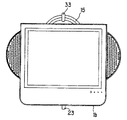
本発明の第34の要旨は、前記表示部の左右に半円形状のスピーカー部を有することを特徴とする。 A thirty-fourth aspect of the present invention is characterized by having semicircular speaker portions on the left and right sides of the display portion.
本発明の第34の要旨によれば、把持部の円環形状は前記表示部前方から見て該スピーカー部と相似して前記表示部上方から突出していることで、バランスを良くすると共に、円形とすることで強度を高めることができる。 According to the thirty-fourth aspect of the present invention, the annular shape of the gripping part is similar to the speaker part as seen from the front of the display part and protrudes from the upper part of the display part. By doing so, the strength can be increased.
本発明の第35の要旨は、把持部を有する薄型の表示部と、該表示部に電源を供給することが可能な電源部とを有する薄型の表示装置であって、該表示装置を遠隔操作するリモートコントロール装置と嵌合する形状に形成されたリモコンホルダーを備えることを特徴とする。 A thirty-fifth aspect of the present invention is a thin display device having a thin display portion having a grip portion and a power supply portion capable of supplying power to the display portion, and the display device is operated remotely. And a remote control holder formed in a shape to be fitted to the remote control device.
本発明の第35の要旨によれば、薄型化が可能となり、かつ電源部を備えることによりモバイル性が生まれた表示部に対して、付随して用いられるリモートコントロール装置の一体的な持ち運びを可能とし、紛失を防止できる等多くのメリットを得られる。 According to the thirty-fifth aspect of the present invention, the remote control device used as an accessory can be integrally carried with respect to the display unit which can be thinned and has a mobile property by providing a power supply unit. And many advantages such as prevention of loss can be obtained.
本発明の第36の要旨は、前記リモートコントロール装置は先端から他端にかけて窄まる形状である一方、前記リモコンホルダーは前記表示装置の上方から下方にかけて窄まる方向に傾斜を有している形状であることを特徴とする。 A thirty-sixth aspect of the present invention is that the remote control device has a shape that narrows from the front end to the other end, while the remote control holder has a shape that has an inclination in a direction that narrows from the top to the bottom of the display device. It is characterized by being.
本発明の第36の要旨によれば、リモートコントロール装置及びリモコンホルダーを上述のような形状とすることにより、表示装置に対するリモートコントロール装置の着脱を容易にすることができ、表示部のモバイル性をより活かすことが可能となる。 According to the thirty-sixth aspect of the present invention, the remote control device and the remote control holder are shaped as described above, whereby the remote control device can be easily attached to and detached from the display device, and the mobility of the display unit can be improved. It is possible to make better use of it.
本発明の第37の要旨は、薄型の表示部が備える挿脱部をスタンド支柱部の挿入穴に挿嵌することでスタンド支柱部による表示部の支持状態とされる薄型表示装置であって、前記表示部の挿脱部が前記スタンド支柱部から抜脱可能であり、前記表示部には充電池が内蔵され、前記スタンド支柱部は電源部を有し、前記スタンド支柱部による表示部の支持状態において前記電源部を通じて前記表示部に内蔵された充電池に充電されることを特徴とする。 The thirty-seventh aspect of the present invention is a thin display device in which the display unit is supported by the stand column by inserting the insertion / removal unit of the thin display unit into the insertion hole of the stand column. The insertion / removal part of the display part is removable from the stand column part, the rechargeable battery is built in the display part, the stand column part has a power supply part, and the display part is supported by the stand column part. In the state, the rechargeable battery built in the display unit is charged through the power supply unit.
本発明の第37の要旨によれば、スタンド支柱部による表示部の支持状態においては表示部の表示及び充電の両方を可能とするとともに、表示部が備える挿脱部を抜脱して表示部を持ち運んだときは、その持ち運び先において充電池を用いて表示部の表示を可能とするので、表示部の持ち運びが容易であるとともにスタンド支柱部を用いたときに表示部の表示を行いながら手軽に充電池の充電を行うことができる。 According to the thirty-seventh aspect of the present invention, the display unit can be displayed and charged in the support state of the display unit by the stand column unit, and the display unit can be removed by removing the insertion / removal unit included in the display unit. When carried, the display unit can be displayed using a rechargeable battery at the destination, making it easy to carry the display unit and displaying the display unit easily when using the stand column. The rechargeable battery can be charged.
[第1の実施形態]
以下、図面を参照して本発明の第1の実施形態を詳細に説明する。
図1は、本実施の形態に係るスタンド式薄型テレビの正面図である。尚、実施形態では、映像、画像等の情報を表示する表示装置1として液晶ディスプレイを例に示すが、プラズマディスプレイ、有機EL(エレクトロルミネッセンス)等種々の薄型の表示装置を用いることができる。
[First Embodiment]
Hereinafter, a first embodiment of the present invention will be described in detail with reference to the drawings.
FIG. 1 is a front view of a stand-type thin television according to the present embodiment. In the embodiment, a liquid crystal display is shown as an example of the
スタンド式薄型テレビは、表示装置1、連結体15、支柱25及びスタンドベース29から構成されるスタンド支柱部30を有している。表示装置1に連結体15を取り付け、スタンドベース29に固定された支柱25に連結体15を着脱自在に形成することで、スタンド支柱部30を用いる第1の使用形態では連結体15を支柱25に挿入してスタンド支柱部30によって表示装置1を支持する状態として用い、スタンド支柱部30を用いない第2の使用形態では、連結体15自体を表示装置1を支持する支持スタンドとして用いるものである。
The stand-type thin television has a stand column portion 30 including the
上記したように、連結体15と支柱25を挿脱可能に形成しているので第1、第2の使用形態の移行を簡単化でき、また、連結体15をスタンドとしても共用できる形状としたことで、簡単な構造で第1、第2の使用形態の移行を実現できた。以下、各構成を詳細に説明する。
As described above, since the connecting
[表示装置]
始めに、表示装置1を図1〜図3を参照しつつ説明する。
表示装置1は、略矩形の正面側フレーム1aと、該正面側フレーム1a内に映像や画像等を表示する液晶ディスプレイ3と、音声出力用のスピーカ5と、背面側カバー7(図2)と、内部に設けたTVチューナ部9(図2)と、着脱充電可能な電源用のバッテリー11(図2)と、底部に設けた設置用レール13(図2)と、を有している。表示装置1は、バッテリー11と図示しないAC電源のいずれの電源からでも駆動できるものである。
[Display device]
First, the
The
液晶ディスプレイ3は、TVチューナ部9で受信した映像(テレビ電話の映像、画像を含む)や、記録媒体、例えば円盤状のDVD、MD,CD,FD等や半導体メモリーに記録、読出した映像、画像(動画、静止画を含む)や、インターネットからの映像、画像、文字、記号等の情報を表示できる。
The
スピーカー5は、正面側フレーム1aの左右両サイドの上方側にそれぞれ半円形に設けてあり、後述する連結体15の取っ手17が正面側フレーム1aの上方から円弧(円環)状に見えるのと併せて、相似形に形成することで、デザイン的にバランス、見栄えを良くすると共に、円形とすることで強度を高めている。表示装置1を持ち運び先で利用する場合、アンテナ部はなるべく受信し易いように外側に取り付けられることが望ましく、本実施形態の場合、表示装置1より外部に飛び出た部分のスピーカー5内に内蔵することが考えられる。そして、表示装置1は持ち運びに適したものであるため、持ち運びの際壁面等にぶつけてしまうことも多いが、その場合、矩形であるよりも円形である方がその衝撃は和らげられる。
The
バッテリー(充電可能な電池)11(図2)は、表示装置1の下方側(スタンドベース29に近い側)に設けられ、図3に示すように背面側カバー7の下方に設けた開閉蓋11aを開けて着脱が行われる。重量の重いバッテリー11の取り付け位置を表示装置1の下方側とすることで、表示装置1の向き、載置の安定性を高めている。なお、表示装置1にバッテリー等の電源部を備えることで表示装置1のモバイル性に寄与しているが、その他の電源部として電源プラグ等を表示部に備えていても持ち運び先で電源プラグを電気配線からの電気を得るためにプラグ差込口に差し込むことにより電源供給が可能となり、モバイル性に寄与する。バッテリーと電源プラグを備えるなど複数の電源部を備えている場合は、持ち運び先でバッテリーにより表示装置1を利用する一方、プラグ差込口があるところでは電源プラグを利用して安定的に電源を供給できるとともにバッテリーに充電することも可能となるなど利用の用途が広がる。
The battery (rechargeable battery) 11 (FIG. 2) is provided on the lower side of the display device 1 (the side close to the stand base 29), and as shown in FIG. 3, the opening /
設置用レール13は、表示装置1をスタンド支柱部30から分離した場合の表示装置1の設置用のレールとなるものであり、表示装置1の下面(スタンドベース29に近い側)に設けてあり、その材質としては滑り止め効果のある材質、例えばゴムやシリコンなどを用いることができ、その形状は、表示装置1の仰角を変更した場合にも追従して設置可能な長さで湾曲(略円弧状(表示装置1側に中心を有する円弧状)を含む)したレール形状(凸状)としている。設置用レール13は、上記作用効果を発揮するように表示装置1の下に所定長さに亘って1箇所以上に設けることができるが、幅を狭くし、複数本並行等に設けることで、上記作用効果を少ない材料で実現できる。
The
[連結体15]
次に、連結体15を図1〜図3を参照しつつ説明する。
連結体15は、環状に形成されており、把持部17と、前記表示装置1の背面側カバー7に固定する固定部19と、略棒状のスタンド兼連結部23と、該スタンド兼連結部23を表示装置1と回動可能に接続する第1の回動軸部21と、を有している。
[Connector 15]
Next, the connecting
The connecting
スタンド兼連結部23は第1の使用形態でスタンド支柱部30の挿入穴27に挿嵌されて表示装置1とスタンド支柱部30とを連結する連結部として機能する。また、第2の使用形態では、スタンド兼連結部23は表示装置1を支持するスタンド部として機能する。また、スタンド兼連結部23は第1の使用形態と第2の使用形態をスタンド支柱部30から挿脱することにより移行させる挿脱部としても機能する。
The stand and connecting
把持部17は、円弧(円環)形状をしており、その円弧状の内側には把持した時の滑り止め防止用のゴム、シリコン等の滑止部材17aが円弧状に形成されている(図1)。
The
また、把持部17は、図6に示すように壁31などに設けた突起、例えばフック33に係合可能とする部位でもある。そこで、第1の回動部21又はスタンド兼連結部23の厚み(正面側フレーム1a−背面側カバー7方向D)が固定部19の厚みよりも大きいので、図2に示すように把持部17は、表示装置1の厚み方向Dのうち固定部19から遠ざかる方向すなわち表示装置1の奥行き方向D1に固定部19に対して斜めに形成している。より具体的には、把持部17の該フック33との係合部分(円弧の先端部分)の前記厚み方向Dの位置すなわち表示装置1の奥行き方向D1の寸法が第1の回動軸部21又はスタンド兼連結部23の表示装置1の奥行き方向D1の寸法と略同様に形成することで、把持部17を壁31により近づけることができ、壁31からの突出長さが短いフック33にも取り付け可能となるとともに、壁掛け状態で液晶ディスプレイ3の表示面は壁31面とほぼ平行にすることができる。
Further, as shown in FIG. 6, the
固定部19は、前記表示装置1の背面側カバー7を挟み、内部シャーシにビス留めにより固定されている。
The fixing
第1の回動軸部21は、表示装置1のスタンド支柱部30に対する挿脱方向Hの長さに関して中心位置よりも下方に位置させることで使用性に合わせて上向き方向への角度調整範囲を広くしており、表示装置1の仰角方向Xの回動後の姿勢を維持する強度でスタンド兼連結部23を挟持している。また、回動軸は表示装置1の幅方向に平行である。
The first
スタンド兼連結部23は、基端部に第1の回動軸部21に回動可能に挟持される回動部23aと、該回動部23aの他端側である先端側にゴム、シリコンなどで形成された滑り止め及び緩衝材として機能する滑止・緩衝材23bとを有する横断面円形(円柱、円筒を問わない)で形成されている。
The stand and connecting
スタンド兼連結部23の長手方向(基端部から先端側の方向)の長さは、図2に示すように、そのスタンド兼連結部23の長手方向の長さを液晶ディスプレイ3と並行するようにした状態で、表示装置1の正面側フレーム1aの底辺部1bまでの長さ以上(同一長さを含む)の長さに形成されている。本実施形態としては表示装置1の正面側フレーム1aの底辺部1bまでの長さが113mmで、底辺部1bから19mm程度の突出量としており、従って、図2(b)の状態を正面から見た図1に示すように、正面側フレーム1aの底辺部1bよりも下方までスタンド兼連結部23が延びる長さを有している。
As shown in FIG. 2, the length of the stand and connecting
このように構成する理由は、以下の通りである。
(1)例えば、薄型表示装置の代表例である液晶ディスプレイの場合、傾斜角度との観点からすると、特に液晶ディスプレイは視野角の課題があることおよび寝そべって液晶ディスプレイを観るなどあらゆる使用シーンに対応した傾斜角度が必要である。それに対応するためには、第2の使用形態としてスタンド兼連結部23を表示装置1の支持する支持スタンドとして用いる場合、該支持スタンドの長さは前記支持スタンドがほぼ平行になった状態で前記表示部の下端辺から突出する長さであることが大きなポイントになる。この突出する長さによって可変角度に大きな自由度が得られる。
The reason for this configuration is as follows.
(1) For example, in the case of a liquid crystal display, which is a typical example of a thin display device, from the viewpoint of the tilt angle, the liquid crystal display has a problem of viewing angle, and can be used in various usage scenes such as watching the liquid crystal display lying down. The required tilt angle is necessary. In order to cope with this, when the stand and connecting
また、設置スペースとの関係からすると、狭いスペースにおいても大きな傾斜角度を確保する必要がある。そのためには、スタンド兼連結部23の表示装置1との連結部分の位置は可能な限り下方に取り付けられるのが望ましい。表示装置1の接地部分(下辺)とスタンド兼連結部23の接地部分(先端)との距離が小さくでき、スタンド兼連結部23がスタンドとして単独で表示装置1を支える場合に省スペースで利用できるからである。
Further, in view of the relationship with the installation space, it is necessary to ensure a large inclination angle even in a narrow space. For this purpose, it is desirable that the position of the connecting portion of the stand and connecting
第1の回動軸部21の位置が前記表示装置の下方にあり、かつ、前記支持スタンドがほぼ平行になった状態で前記表示部の下端辺からやや突出する長さであると、狭いスペースで大きな傾斜角度が得られる。
If the position of the first
(2)薄型表示装置の場合は、壁掛けになることも特徴の一つであるが、その際に前記支持スタンドの長さが長いほど、安定的に取り付けられるという利点がある。 (2) In the case of a thin display device, it is one of the features that it is wall-mounted, but there is an advantage that the longer the support stand is, the more stable it can be attached.
なお、上記した把持部17とスタンド兼連結部23及び第1の回動部21は連結体15として一体形成して表示装置1に取り付けられているが、別々に取り付けられていても良いことはもちろんである。ただし、一体形成とした方が組み立て容易となり、製造コストが削減できるという利点がある。
In addition, although the above-mentioned holding | grip
[スタンド支柱部30]
次に、スタンド支柱部30は支柱25及びスタンドベース29から構成され、これらを図1〜図5を参照しつつ説明する。
支柱25は、スタンド兼連結部23の回動部23aを除いた横断面円形の棒状部分を挿脱自在とする挿入穴27を形成できる長さの柱状部材であり、スタンドベース29上に起立状態に固定して形成されている。
[Stand post 30]
Next, the stand support | pillar part 30 is comprised from the support |
The
挿入穴27は、横断面円形の穴であり、スタンド兼連結部23を挿入した状態でスタンド兼連結部23の滑止・緩衝材23bが挿入穴27の底部に当接してスタンド兼連結部23を支持している。また、挿入穴27の径は、スタンド兼連結部23の挿脱自在で、且つ、そのスタンド兼連結部23の長手方向軸を中心にスタンド兼連結部23が回転可能な隙間を有する大きさに形成されている。
The
スタンドベース29は、支柱25及び連結体15を介して表示装置1を所定高さに支持できる大きさを有する。
The
次に、上記説明したスタンド式薄型テレビの作用効果を説明する。
先ず、スタンド支柱部30を使用する第1の使用形態は、図2(a)から(b)に示すように表示装置1の背面側に固定した連結体15のスタンド兼連結部23を支柱25の挿入穴27に挿入することで表示装置1の支持状態とされる。この第1の使用形態での表示装置1の仰角方向Xの調整は、図3に示すように、第1の回動軸部21をスタンド兼連結部23の回動部23aに対して回動することで行われる。また、この第1の使用形態での表示装置1の水平方向Yの向きの調整は、図4に示すように、支柱25に対してスタンド兼連結部23を中心軸として表示装置1を水平方向Yに回動させること、すなわち、挿入穴27内でスタンド兼連結部23をその長手方向を軸として回転させることで行われる。スタンド兼連結部23をスタンド支柱部30に挿入穴27に挿入して使用する場合、スタンド兼連結部23の長さが長いほど安定して表示装置1が支持されるが、スタンド兼連結部23をスタンド支柱部30の挿入穴27に挿入することによりスタンド支柱部30によって表示装置1を支持できる程度の長さであればよい。逆に、スタンド兼連結部23をスタンド支柱部30の挿入穴27に挿入して表示装置1が支持できず、従来例(図26)のようにビス等なしでは転倒してしまうような長さであってはいけない。具体的な長さは、表示装置1の大きさ・重量、スタンドベース29の大きさ、スタンド支柱部30の高さ等によって設計することとなる。
Next, functions and effects of the above-described stand type thin television will be described.
First, in a first usage pattern in which the stand column 30 is used, as shown in FIGS. 2A to 2B, the stand and connecting
次に、スタンド支柱部30を使用せず、表示装置1を支持するスタンドとしてスタンド兼連結部23を用いる第2の使用形態は、図2(b)から(a)に示すように,例えば把持部17を持ってスタンド兼連結部23を支柱25の挿入穴27から抜き取り、図5に示すように表示装置1の下面に設けた設置用レール13とスタンド兼連結部23の先端に設けた滑止・緩衝材23bにより表示装置1を支持することで形成される。
Next, as shown in FIGS. 2 (b) to 2 (a), the second usage pattern in which the stand / connecting
スタンド兼連結部23の長さを、表示装置1の底辺部1bよりも長く設けているので、液晶ディスプレイ3に対するスタンド兼連結部23の角度を調整することで、設置用レール13と滑止・緩衝材23bとの間隔を広めに取りながら安定して液晶ディスプレイ3の仰角X(液晶ディスプレイ3の上下方向の向き)を調整することができる。
Since the length of the stand and connecting
以上のように表示装置1の下面に設けた設置用レール13とスタンド兼連結部23が表示装置1を支えているので、表示装置1とスタンド兼連結部23の少ないスペースがあれば表示装置1を載置できる。
As described above, the
また、スタンド兼連結部23により仰角Xを調整するので、簡単な構造で、かつ、少ないスペースで表示装置1の仰角X方向も調節できる。
Further, since the elevation angle X is adjusted by the stand and connecting
さらに、支柱25を必要としないので、テーブル上などの高い位置にも簡単に移動でき、且つ、仰角Xを調整することもできる。
Further, since the
また、図6に示すようにスタンド兼連結部23をスタンドとして使用せず、把持部17を壁31に掛ける取り付け部として使用することで、表示装置1を壁掛けTVとして利用できる。この場合、把持部17を円弧状に形成することでフック33が円弧の頂点部分と係合するので、表示装置1が傾いたりすることがなく、安定した姿勢を保つことできる。
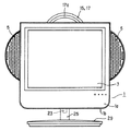
Further, as shown in FIG. 6, the
図2(a)の状態からそのままフック33に掛けて図7に示すように壁掛けTVとして利用する場合に、表示装置1の底辺部1bよりもスタンド兼連結部23が突出して見える場合には、図8に示すようにスタンド兼連結部23を、回動軸部21を中心に略180度表示装置1の上辺側に回動させることで底辺部1bからのスタンド兼連結部23の突出(露出)を抑えることができ、美観を損なうことを防ぐことができる。また、表示装置1を壁掛け使用の状態で、回動軸部21を中心にスタンド兼連結部23の回動量を制御することで、壁掛け状態での表示装置1の仰角も調整できる。
In the case where the stand and connecting
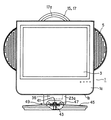
ここで、第1の回動軸部21の表示装置1の奥行き方向の寸法を、把持部17の先端部分の表示装置1の奥行き方向の寸法よりも大きく設計していると、壁掛けTVとして利用したとき表示装置1は俯角を有することになり、壁の上位に掛けたときに下方から見易く、壁掛けTVとして好適である。このとき、スタンド兼連結部23は表示装置1の仰角又は俯角を調整する角度調整部として機能している。
Here, if the dimension in the depth direction of the
また、把持部17の先端部分は図7のように正面側フレーム1aの上端部より突出していれば、壁掛けTVとして好適である。
Moreover, if the front-end | tip part of the holding
さらに、壁掛けTVと第2の使用形態との関係では、スタンド兼連結部23はスタンド兼角度調節部として機能している。
Further, in the relationship between the wall-mounted TV and the second usage pattern, the stand /
尚、第1の回動軸部21は、表示装置1のスタンド支柱部30に対する挿脱方向Hの長さに関して中心位置よりも下方に位置しているので、回動軸部21を中心にスタンド兼連結部23を略180度回動させてもスタンド兼連結部23が表示装置1の上方に突出することはない。
In addition, since the 1st rotation axis |
以上説明した第1の実施形態に係るスタンド式薄型テレビでは、表示装置1の水平方向Yの回動を支柱25に対して連結体15を回動可能とする手段で説明したが、それに限定するものではなく、スタンドベース29に対して表示装置1、連結体15、及び支柱25が水平方向Yに関して回動する第2の実施の形態を以下に説明する。
In the stand-type thin television according to the first embodiment described above, the rotation of the
[第2の実施形態]
以下、図面を参照して本発明の第2の実施形態を詳細に説明する。尚、上記した構成と同一部分には同一符号を付し、その説明を省略し、上記実施の形態との相違部分を中心に説明する。上記実施の形態との相違部分は、概略するとスタンド兼連結部の横断面形状を円形から略矩形等に変更し(図9、図14)、該スタンド兼連結部の形状変化にあわせて支柱の形状を変更し(図9、図14)、また、スタンドベースに対して支柱を水平方向Yに回動可能とし(図9)、さらに把持部17に表示装置1のリモートコントロール装置53を保持するリモコンホルダー51を設けた(図15から17)点にある。以下、詳細に説明する。
[Second Embodiment]
Hereinafter, a second embodiment of the present invention will be described in detail with reference to the drawings. In addition, the same code | symbol is attached | subjected to the same part as above-described structure, the description is abbreviate | omitted, and it demonstrates centering on a different part from the said embodiment. The difference from the above-described embodiment is that the cross-sectional shape of the stand and connecting portion is changed from a circular shape to a substantially rectangular shape or the like (FIGS. 9 and 14). The shape is changed (FIGS. 9 and 14), the column can be rotated in the horizontal direction Y with respect to the stand base (FIG. 9), and the
本実施形態に係るスタンド兼連結部35は、基端部に第1の回動軸部21に回動可能に挟持される回動部35aと、該回動部35aの他端側である先端側にゴム、シリコンなどで形成された滑り止め及び緩衝材として機能する滑止・緩衝材35bとを有し、第1の回動軸部21の回動軸方向(支持軸方向)に長い横断面形状、例えば略矩形状に形成されている。
The stand and connecting
スタンド兼連結部35を第1の回動軸部21の回動軸方向に長い断面矩形形状にすることで、連結体15の表示装置1の奥行き方向D1(図10)の寸法を小さくしつつ、第2の使用形態(スタンド支柱部30から分離した場合)での表示装置1を支える安定性を増すことができる。すなわち、第2の使用形態での設置場所との接触部位は、第1の実施の形態のスタンド兼連結部23の場合には、設置用レール13と滑止・緩衝材23bで囲まれる形状は略三角形となるが、第2の実施の形態のスタンド兼連結部35の場合には、滑止・緩衝材35bが滑止・緩衝材23bに較べて第1の回動軸部21の回動軸方向(表示装置1の下部の長手方向)に長いので、設置用レール13と滑止・緩衝材35bで囲まれる形状は、長辺側が設置用レール13間となり、短辺側が滑止・緩衝材35bの長さとなる4角形や台形形状となり、表示装置1に対して同じ傾きの場合にはスタンド兼連結部35の方が表示装置1を支える面積が大きくなり、より安定性が高くなる。
By making the stand and connecting
スタンド兼連結部35の長手方向(基端部から先端側の方向)の長さは、図9、図10に示すように、そのスタンド兼連結部35の長手方向の長さを液晶ディスプレイ3と並行するようにした状態で、表示装置1の正面側フレーム1aの底辺部1bまでの長さ以上(同一長さを含む)の長さに形成されている。本実施形態としては表示装置1の正面側フレーム1aの底辺部1bまでの長さが113mmで、底辺部1bから19mm程度の突出量としており、従って、図10(b)状態を正面から見た図9に示すように、正面側フレーム1aの底辺部1bよりも下方までスタンド兼連結部35が延びる長さを有している。
As shown in FIGS. 9 and 10, the length of the stand and connecting
本実施形態に係る支柱37は、図14に示すように横断面外形が楕円形状に形成され、スタンド兼連結部35の横断面の略矩形形状と相似形の挿入穴39を設けている。
As shown in FIG. 14, the
挿入穴39は、横断面略矩形の穴であり、スタンド兼連結部35を挿入した状態ではスタンド兼連結部35の滑止・緩衝材35bが挿入穴39の底部に当接してスタンド兼連結部35を支持している。また、挿入穴39の横断面の大きさは、挿入したスタンド兼連結部35が不快なガタツキを生じず、スタンド兼連結部35が挿脱自在となる大きさに形成されている。従って、表示装置1の水平方向への回動力は、連結体15とスタンド兼連結部35を介して支柱37に伝達される。
The
支柱37とスタンドベース45には、互いに水平方向Yに回動可能とするため、従来技術で示した嵌合金具105、嵌合受け金具106と同様に、嵌合金具41と嵌合受け金具43が設けられ、嵌合金具41及び嵌合受け金具43は互いに回動可能に係合するような形状に作られている。
Since the
また、支柱37のスタンドベース45側底辺には、スタンドベース45との回動時に不快な摩擦音などの発生を抑えたり、接触傷を抑えるために、円滑部材47を設けている。円滑部材47は、スタンドベース45の材質との関係で適宜選択できるが例えば、プラスチック、硬質のゴムやシリコンなどを使用できる。
In addition, a
支柱37とスタンドベース45の連結部分では、支柱37の円滑な回動の実現と前記スタンドベース45回動時の摩擦音や接触傷を抑えるためにするために、図9に示すように、回動中心となる嵌合金具41と嵌合受け金具43から離れるほど隙間49を大きく形成するように設けている。尚、スタンドベース45は、支柱37及び連結体15を介して表示装置1を所定高さに支持できる大きさを有する。
As shown in FIG. 9, the connecting portion between the
また、本実施の形態では、図15〜19に示すように把持部17に表示装置1のリモートコントロール装置53を保持するリモコンホルダー51を設けている。本実施の形態の表示装置1は、支柱37から分離して使用できるため、表示装置1とリモートコントロール装置53も分離されてしまう不具合を生じる可能性があるが、表示装置1と共に支柱37より分離する把持部17にリモコンホルダー51を設けることで、移動先にリモートコントロール装置53を付帯させることができるため、うっかりリモートコントロール装置53の置き忘れや紛失などの事態を事前に回避できる。
In the present embodiment, as shown in FIGS. 15 to 19, a
本実施形態でのリモコンホルダー51は、図18のように、表示装置1側に取り付ける取り付け部51aと、リモートコントロール装置53と係合して保持できる形状をした2つの爪片51bを有している。
As shown in FIG. 18, the
具体的には、図19のようにリモートコントロール装置53が、その先端53aが他端53bにかけて大きく窄まる形状をしている場合、図19のようにリモートコントロール装置53の窄まり形状をしている端部53b側から2つの爪片51bに対して挿入する形で係合させると、大きめに形成された先端53a側で引っ掛かり、図15のように係合状態となる。この場合、リモコンホルダー51の爪片51b−51b間隔は、表示装置1の上辺側から下辺側に対して窄まるように適度な傾斜を有する形状とすることで窄まり形状のリモートコントロール装置53との嵌合が良くなり、望ましい。
Specifically, when the
また、リモコンホルダー51をプラスチックなどの適度な柔軟性を持った材料を用いて形成し、且つ、2つの爪片51b−51b間でリモートコントロール装置53を挟圧可能な形状に形成した場合、リモートコントロール装置53をリモコンホルダー51への挿入方向に多少の力を加えると爪片51bがしなってリモートコントロール装置53をリモコンホルダー51内に狭圧係合状態とすることができる。
Further, when the
リモコンホルダー51の爪片51bを、リモートコントロール装置53を保持した時にやや締め付けるくらいに設計しておくと、リモートコントロール装置53の形状は先端(53a側)大きくしたり、他端(53B側)が窄まり形状にしたりする必要はなく、いろんな形状のリモートコントロール装置53を保持できる。
If the
尚、リモコンホルダー51の形状や取り付け位置などは限定するものではなく、表示装置1の裏面に直接取り付けるなどでもよい。表示装置1と共にリモートコントロール装置53を移動できる形状、形態、場所であればよい。また、リモコンと嵌合する形状であればどのような形状であってもよい。表示装置1自体にリモートコントロール装置53を嵌合して同時に持ち運べるようにしてもよい。
The shape and mounting position of the
以上、第2実施形態での相違点を中心に構成、作用効果を説明したが、第1の実施形態に記載した作用効果も奏することは言うまでもない。 As mentioned above, although a structure and an effect were demonstrated centering on the difference in 2nd Embodiment, it cannot be overemphasized that the effect described in 1st Embodiment is also show | played.
尚、前記スタンド兼連結部35は、第1の回動軸部21の回動軸方向に長い横断面略矩形状で説明したが、横断面略矩形状に限定するものではなく、スタンド兼連結部35の回動が支柱37へ伝達可能な形状であればよい。
In addition, although the said stand and
また、リモコンホルダー51については第2の実施形態で説明したが、第1の実施の形態にも適用できることはいうまでもない。
Further, although the
また、前記第1、第2の実施形態では、挿入穴27、39からスタンド兼連結部23、35を引き抜く構成であるが、挿入穴27、39からスタンド兼連結部23、35の抜けを防止する図示しない棒状の連結ピンを支柱25、37を貫通し、スタンド兼連結部23、35に挿入するように形成できる。係る構成とすることで、把持部17を持ち上げることで表示装置1からスタンドベース29、49までを一体として移動することができる。抜け防止手段としては連結ピンを挿入する方法に限らないことはもちろんである。より詳細に、第3の実施の形態として以下説明する。
In the first and second embodiments, the stand and connecting
[第3の実施形態]
以下、図面を参照して本発明の第3の実施形態を詳細に説明する。尚、上記した構成と同一部分には同一符号を付し、その説明を省略し、上記第2の実施の形態との相違部分を中心に説明する。上記第2の実施の形態との相違部分は、概略するとスタンド兼連結部に抜け防止用の窪み59と、挿入方向規制用の突起61とを設け、長さを液晶ディスプレイ3と並行するようにした状態で、表示装置1の正面側フレーム1aの底辺部1bまでの長さ以下(同一長さを含む)の長さに変更し(図20、図21)、該スタンド兼連結部の抜け防止機構を支柱に設け(図20〜図24)、また、支柱とスタンド兼連結部の連結時及び連結後の表示装置1の仰角を規制するために第1の回動軸部21に突起55と支柱の上端形状を変更し(図20、図21)、第1の回動軸部21とスタンド兼連結部間に表示装置1の仰角として推奨する角度の報知機構を設けた(図25)点にある。以下、詳細に説明する。
[Third Embodiment]
Hereinafter, a third embodiment of the present invention will be described in detail with reference to the drawings. In addition, the same code | symbol is attached | subjected to the same part as above-described structure, the description is abbreviate | omitted, and it demonstrates centering on a different part from the said 2nd Embodiment. The difference from the second embodiment is that the stand and connecting portion is provided with a
[スタンド兼連結部57]
本実施形態に係るスタンド兼連結部57は、スタンド兼連結部35と同様に略矩の断面形状だが、その長さを表示装置1の正面側フレーム1aの底辺部1b(設置用レール13)を越えない長さ(同一長を含む)であって少なくとも第2の使用形態でスタンドとして表示装置1を支えることのできる長さに形成されている。スタンド兼連結部57をこのような長さにすることで、第2の使用形態での表示装置1の重心をスタンド兼連結部57側(背面側カバー側)に掛けることとなり、転倒するような外力が加わっても表示装置1は背面側カバー7側に転倒するのみで、デリケートな表示画面の破損を確実に防ぐことができる。
[Stand and connecting part 57]
The stand and connecting
スタンド兼連結部57には、支柱65と連結した状態での抜け防止用の窪み59(図20)と、支柱65への挿入方向を1方向に規制するため規制突起61(図21)を設けている。
The stand /
[スタンド兼連結部側抜け防止機構]
抜け防止用窪み59(図20)は、スタンド兼連結部57の滑止・緩衝材35bを表示装置1の底辺部1b側に向けた状態で表示装置1と対向する面の裏面側であって、その長手方向(回動部35a−滑止・緩衝材35b方向)の自由端側(滑止・緩衝材35b側)よりに形成されている。抜け防止用窪み59の形状は、スタンド兼連結部57の幅方向に長い略三角柱状であって、自由端側(滑止・緩衝材35b側)に向かって徐々に窪みの深さを深く形成している。
[Stand and connecting part side slip prevention mechanism]
A recess 59 (FIG. 20) is provided on the back side of the surface facing the
[挿入規制機構]
規制突起61(図21)は、スタンド兼連結部57の抜け防止用窪み59の裏面側に、スタンド兼連結部57の支柱65への挿入方向に垂直方向(「挿入垂直方向」と略記する場合がある)に延びる山形、凸形部である。規制突起61はスタンド兼連結部57の支柱65への挿入方向を1方向に規制する挿入規制機構の一例であり、規制突起61の位置、形状に限定するものではない。挿入規制機構を、例えば、突起や溝(凹み、窪み、切欠き)にて形成する場合にはスタンド兼連結部57の支柱65に挿入される部分に挿入垂直方向に山形、凸形等の突起や溝を形成すればよく、また、突起や溝を設けずにスタンド兼連結部57の断面形状、すなわち支柱65に挿入される形状を1方向に規制する断面形状、例えば断面台形等に形成してもよい。
[Insertion restriction mechanism]
The restricting protrusion 61 (FIG. 21) is formed on the back side of the
上記のように挿入規制機構を設けることで、予期せぬ方向に表示装置1が位置することによりアンバランスな第1の使用形態としたり、転倒を防ぐことができる。すなわち、表示装置1側に重心が掛かる支柱65の転倒を防止するためにスタンドベース45(図21)は支柱65より後方側に較べて表示面側に大きく迫出す形状としているが、誤って支柱65にスタンド兼連結部57を逆向きに挿入すると転倒の可能性があるので、挿入規制機構を設けることで係る転倒の可能性を確実に無くすことができる。
By providing the insertion restricting mechanism as described above, the
[回動規制部材]
支柱65とスタンド兼連結部57の連結時と連結後の表示装置1の仰角を規制するために第1の回動軸部21に突起55を設けている(図20、図21)。
[Rotation restricting member]
In order to restrict the elevation angle of the
突起55は、第1の回動軸部21にスタンド兼連結部57の回動方向に所定長さに形成されている。本実施形態では第1の回動軸部21の突起55の形成していない表面をスタンド兼連結部57の回動軸心から等距離の略半円形状に形成しており、突起55を形成した部分ではスタンド兼連結部57の回動軸心からの距離が突起55を設けない部分よりも長くすることで、突起55が支柱65と干渉する状態では抜け防止機構が正常に機能せずに不安定な姿勢となり、許容範囲越えた姿勢での取り付けであることをユーザに知らせることができる。
The
また、抜け防止機構が正常に機能する第1の使用形態であっても不安定なバランス状態となるような仰角方向の傾斜を行う場合には突起55の下方側面55aが支柱65の上部面69の後方エッジ69a(図21)に干渉、衝突し、それ以上の仰角方向への回動を規制し、第1の使用形態でのアンバランスな使用を未然に防ぐことができる。
In addition, even when the first use mode in which the removal prevention mechanism functions normally is performed, the lower side surface 55a of the
また、突起55を支柱65の上部面69と係合又は近接し、表示装置1と同期して回動する部分、例えば、第1の回動軸部21に設けることで、第2の使用形態での表示装置1の仰角規制をすることなく、第1の使用形態へ移行する時の姿勢規制と、第1の使用形態での表示装置1の無理な仰角方向の回動規制とを実現でき、結果として、第1の使用形態での表示装置1の仰角変更許容範囲と第2の使用形態でのその許容範囲とを異なる範囲とでき、使用形態に合せた安全な使用を確保できる。
Further, the
尚、前記規制を実現する手段としては、スタンド兼連結部57の回動軸から第1の回動軸部21表面までの距離が異なる形状(規制範囲の距離を長く)であればよく、例えば、突起55に替えて第1の回動軸部21の表面を楕円等に形成することでも同様の作用効果を得ることが出来る。尚、本実施の形態では、表示装置1の設置面の垂直方向からの傾斜角度を約10度傾けられるように突起55、又は突起55及び支柱65の後方エッジ69aを形成している。
In addition, as a means for realizing the restriction, it is sufficient if the distance from the rotation shaft of the stand and connecting
[把持部17b]
表示装置1は持ち運びを容易とするため、把持部17bを備えている。この把持部17bは掴むことが可能なものであればよい。本実施形態では、支柱65とスタンド兼連結部57の挿脱を容易とするために把持部17bは把持部17よりも固定部19に対する傾斜角度を少なくしている。これにより、把持部17bを持った時に表示装置1が振らつくことがないので簡単、スムーズに第1、第2の使用形態の移行を可能とできる。
[
The
また、把持部17bは円還形であれば持ち運び及び壁掛けに便利であるが、持ち運びには矩形、壁掛けには三角形の形状も適している。
Further, the
[支柱65]
支柱65は、前記第2の実施形態の支柱37と較べて概略すると上部面69形状、挿入穴71形状、開閉蓋73、スタンド兼連結部57の抜け防止機構77等が異なる。(図20〜図24)。
[Prop 65]
The
支柱65の上部面69は、第1の回動軸部21の下面と凹凸係合するように表示装置1の表示面側から裏面側方向に向かって徐々に高さを高くするように形成している。係る形状により、第1の使用形態で支柱65と第1の回動軸部21間の隙間を減らし、分離可能な表示装置1側と支柱65側の見た目の一体感を出すことができ、デザイン的に優れたものとできる。さらに、支柱65へのスタンド兼連結部57の挿入時に、突起55が上部面69と接触するような挿入である場合には、上部面69と第1の回動軸部21の下面が凹凸係合せずに隙間が生じるため、不適切な挿入であることをユーザに認識させることが可能となる。
The
挿入穴71は、スタンド兼連結部57の挿入する穴であり、規制突起61を設けたスタンド兼連結部57の挿入垂直方向の断面形状と略相似形に形成している(図22)。
The
[干渉防止用部材]
挿入穴71内には、スタンド兼連結部57と所定隙間を維持する干渉防止用部材としてブロック状、棒状、及び/又は板状等のゴム、プラスチック、シリコン等の緩衝材72a,72bを挿入穴71内の長手方向中心より開口側に設けている。緩衝材72a,72bは、挿入垂直方向に関して環状又は部分的に設けてもより。挿入穴71内に挿入されたスタンド兼連結部57は、軸側側面を緩衝材72a,72bを介して、先端部を滑止・緩衝材35bとを介してそれぞれ挿入穴71内に支持されるため、支柱67に対する表示装置1の不快なぐらつきや干渉音を減らすことができる。
[Interference prevention member]
In the
また、挿入穴71内のスタンド兼連結部57の滑止・緩衝材35bとの対向部分89或いはその近傍を磁石にて形成し、該滑止・緩衝材35bを金属にて形成することで、第1の使用形態では挿入穴71底部の磁石にスタンド兼連結部57の先端が吸引されることで支柱67内のスタンド兼連結部57の不快なぐらつきや干渉音を減らすことができる。
Further, by forming a
[蓋部材73]
開閉蓋73は、挿入穴71内上部に、一端側を軸支され、常に挿入穴71の開口を閉じる方向に付勢された蓋部材である(図22,23)。第2の使用状態では開閉蓋73が挿入穴71開口を閉じるため、挿入穴71内の汚れを防げる。
[Cover member 73]
The open /
[支柱側抜け防止機構]
図23は図22のB−B断面斜視図であり、図24は図23の抜け防止機構77部分の裏面側からの透視図であり、図25は図24の状態から操作部79を押圧した時の抜け防止機構77の作用を説明する透視図である。
[Protruding side prevention mechanism]
23 is a cross-sectional perspective view taken along the line BB in FIG. 22, FIG. 24 is a perspective view from the back side of the
図23に示すように抜け防止機構77は、ユーザの操作部79と、第1の使用状態で抜け防止用窪み59(図20)に挿入、凹凸係合し、操作部79の操作(例えば、押圧)により該抜け防止用窪み59から抜け、凹凸係合を解除する挿抜部85と、操作部79と挿抜部85とを往復直線摺動可能に収納するフレーム81と、操作部79と挿抜部85をそれぞれフレーム81内から外方向に付勢するバネ83、87で形成されている。
As shown in FIG. 23, the
操作部79は、指との接触面を多くし、押圧力を分散させるために中央を窪ませた面取りした操作ボタンを有し、挿抜部85の抜け防止用窪み59に挿入する部位は抜け防止用窪み59の形状に相似形の略三角柱状としている。操作部79と挿抜部85のフレーム81内での摺動方向は、互いに略垂直方向であり、バネ83、87の付勢方向も略垂直方向としている。
The
フレーム81の側壁には、図24に示すように操作部79の移動方向にその移動をガイドする第1ガイド孔81aと、挿抜部85の移動方向にその移動をガイドする第2ガイド孔81bとを設けており、該第1ガイド孔81aには操作部79のガイド突起79aが、該第2ガイド孔81bには挿抜部85のリンクロッド85aがそれぞれ往復摺動可能に係合している。
On the side wall of the
操作部79には、操作部79の移動に伴ってリンクロッド85aを第2ガイド孔81bに沿って押圧変位させる傾斜辺であるリンク辺79bを設けている。
The
上記構成により、支柱65にスタンド兼連結部57を連結した状態(図23)で把持部17bを引き上げた場合には、挿抜部85の第1干渉面85cと対向するスタンド兼連結部57の抜け防止用窪み59の第2干渉面59aとが干渉し、支柱67とスタンドベース45を一体として引き上げ可能となり、第1の使用状態での移動を可能としている。
With the above configuration, when the gripping
第2の使用状態に移行する場合には、操作部79をバネ83の付勢力に抗して押圧することで、図24(a)(b)に示すようにガイド突起79aが第1ガイド孔81a内を移動しつつリンク辺79bがリンクロッド85aを押圧することでリンクロッド85aが第2ガイド孔81d内で後方(挿抜部85を抜け防止用窪み59内から引き抜く方向)に移動し、それと同期して該リンクロッド85aを形成する挿抜部85がバネ87に抗して後方に移動し、挿抜部85が抜け防止用窪み59内から引き抜かれる。係る操作部79のスタンド兼連結部57の挿入方向H1への押圧状態で把持部17bを引き上げることで、挿抜部85の第1干渉面85cが第2干渉面59aと干渉することなく、支柱67からスタンド兼連結部57が引き抜かれる。このとき、操作部79に対してスタンド兼連結部57の挿入方向H1へ力を作用させて支柱部の持ち上がりを抑えつつ、把持部17bを持ち上げることによりスタンド兼連結部57のスタンド支柱部からの離脱方向H2に力が作用するので、反作用の力が加わって抜脱がし易く、かつ安定した抜脱ができる。
When shifting to the second use state, the
[報知機構]
図25は、表示装置1の推奨仰角度の報知機構の一例として、第1の回動軸部21(図20)とスタンド兼連結部57の回動部35aに設けた発音部91を示している。
[Notification mechanism]
FIG. 25 shows the sounding
発音部91は、第1の回動軸部21に締結される軸受け部22に設けた長孔22c(図25(b))に回転可能に設けたローラー93と、該ローラー93と係合する切欠き94a,94bを設けた板状のローラー受け部95と、該ローラー93を該ローラー受け部95側に常に付勢する付勢手段97とで構成されている。
The
軸受け部22は、ネジ止め等により第1の回動軸部21に締結される締結面22aと、回動部35aの回動軸36を軸支する軸支面22bと、該軸支面22bのローラー93を回転自在に許容する長孔22cを有している。
The bearing
長孔22cは、回動軸36の軸受け22dに近接し、且つ、切欠き94a,94bに対向する位置にあり、短径がローラー93を所定隙間を持って遊嵌する。長孔22cの長手方向のローラー93の移動を、一端側を軸受け22dが規制し、他端側を付勢手段97の基端部97aが規制している。尚、長孔22cは少なくともローラー93が付勢手段97の付勢力を受けて該付勢方向に関して揺動自在となる大きさ、形状であればよい。
The
ローラー93は球を用いているが、回動自在な形状、例えば、円筒型、円錐型であってもよい。またローラー95の材質は金属を用いているが、ローラー受け部95との回転接触音、切欠き94a,94bとの係合時の報知音等を考慮し、金属、樹脂等の任意の素材を選択できる。
The
ローラー受け部95は、軸支面22bに軸支される回動軸36から鍔状に突出した板状部材であり、該回動軸36から略等距離にリング状に切り欠いた切欠き94a,94bを設けている。ローラー受け部95は平板状に形成しているがローラー93との当接部位にローラー93の誘導レールを設けることでローラー受け部95に対するローラー93の移動方向の案内となり、スムーズな回転ができる。誘導レールとしては、例えば、ローラー93を誘導可能な幅の溝で形成できる。
The
切欠き94a,94bは、前記ローラー93が通過しない開口を有し、係合したローラー93の安定性を高めるためにローラー93の直径未満の径を有するリング状に形成することでローラー93のセンタリング効果を得ている。さらに、切欠き94a,94bの開口縁には、該ローラー93と凹凸係合する湾曲面(接触面)94cを形成することで、切欠き94a,94bに係合するローラー93の安定性、センタリング効果を高めている。
The
切欠き94aは、第2の使用形態から第1の使用形態に移行する時に支柱65にスタンド兼連結部57を連結する時の推奨角度、すなわち、表示装置1に対してスタンド兼連結部57が略並行(略0度)となる時にローラー93が対向する位置に設けられ、切欠き94bは、第2の使用形態で表示装置1の推奨傾き角度、例えば、設置面の垂直方向に対して表示装置1の表示画面が約15度の傾きとなる時にローラー93が対向する位置に設けられている。尚、切欠きの形成個数、位置は、これに限定するものではなく、ユーザに推奨角度として知らせたい事象により任意に変更できる。
The
付勢手段97は、ローラー93をローラー受け部95側に常に付勢しており、軸支面22bのローラー受け部95側で基端部97aをネジ99にて締結され、軸支面22bの縁部で折り返すU字状に形成され、自由端近傍の腹部面97bがローラー93をローラー受け部95に所定の付勢力で押圧している。
The urging means 97 constantly urges the
以上の構成により、ローラー93が切欠き94aに係合した状態からスタンド兼連結部57を軸回転させると回動軸36及びローラー受け部95も、ローラー93が付勢手段97から受ける付勢力とローラー93と切欠き94a間のセンタリング力に抗して回転し、ローラー93がローラー受け部95の平坦面を転がり、切欠き94bの湾曲面94cと凹凸係合した時に付勢手段97から受ける付勢力とローラー93と切欠き94b間のセンタリング力により「カチ」との推奨角度を告げる報知音が鳴る。よって、使用者は推奨角度を報知されるので、安全な使用であることを知ることが出来き、ユーザフレンドリーな装置とできる。尚、切欠き94bから切欠き94aへの回動も同様であり、支柱65に挿入するスタンド兼連結部57の角度をユーザが「カチ」との推奨角度を告げる報知音で知ることができ、安全な角度であることを認識できる。
With the above configuration, when the stand and connecting
尚、付勢手段97は板バネに限定するものではなく、常にローラー93をローラー受け部95に押圧する弾性部材、例えばゴムでもよい。
The biasing means 97 is not limited to a leaf spring, and may be an elastic member that constantly presses the
また、報知機構として推奨角度をユーザに聴覚的に知らせる構成、例えば発音部93を説明したが、その構成は限定するものではなく角度変化に伴って音声を出力できる構成であればよい。また、報知音を例えば、発光素子、発光部材により視覚的にユーザに推奨角度を知らせることにより同様の効果を得ることも出来る。
In addition, the configuration in which the recommended angle is audibly notified to the user as the notification mechanism, for example, the
また、第3実施の形態の構成を第1の実施の形態の構成に適用することで同様の作用効果を得ることが出来ることは言うまでもない。 Needless to say, the same effects can be obtained by applying the configuration of the third embodiment to the configuration of the first embodiment.
次に、第1の使用形態時に表示装置に内蔵されたバッテリーを充電する場合について第4の実施の形態として以下に説明する。尚、第4の実施の形態では、前記第3の実施の形態との相違を中心に説明する。 Next, the case where the battery built in the display device is charged in the first usage pattern will be described below as a fourth embodiment. Note that the fourth embodiment will be described with a focus on differences from the third embodiment.
[第4の実施形態]
本実施の形態のスタンド兼連結部57bは、図26に示すように前記第3の実施の形態のスタンド兼連結部57の滑止・緩衝材35bの一部に、表示装置1に内蔵されたバッテリー11と電気的に接続されたコネクタ部C1を設けている。
[Fourth Embodiment]
As shown in FIG. 26, the stand and connecting
本実施形態のコネクタ部C1は、滑止・緩衝材35bから露出する、後述するコネクタ部C2との接点を有する。前記接点形状は、限定するものではなく、例えば平面形状、メス型ピン形状等で形成できる。
The connector part C1 of this embodiment has a contact point with a connector part C2, which will be described later, exposed from the anti-slip /
導線Lは、コネクタ部C1からスタンド兼連結部57内を通ってバッテリー11に接続されている。
The conducting wire L is connected to the
一方、コネクタ部C1への電源供給側となるスタンド支柱65bは、前記第3の実施の形態の対向部分89のうち、前記コネクタ部C1との対向部分にコネクタ部C2を有しており、第1の使用形態において前記コネクタ部C1との間で電気的接続を確保している。
On the other hand, the
前記コネクタ部C2は、交流電源用プラグP1からの交流電流を直流電流に変換する直流電源供給部(AC−DC変換器を含む)P2に接続されている。 The connector part C2 is connected to a direct current power supply part (including an AC-DC converter) P2 that converts alternating current from the alternating current power supply plug P1 into direct current.
従って、第1の使用形態では、電源プラグP1を図示しないプラグ差込口に差し込むことによって電源供給部P2からの直流電流がコネクタ部C2、コネクタ部C1、及び導線Lを介してバッテリー11に供給される。
Therefore, in the first usage pattern, the direct current from the power supply part P2 is supplied to the
上記構成により、第2の使用形態では表示装置1のみを持ち運んで、バッテリー11からの電源供給によりその持ち運び先で表示装置1の駆動が可能となり、第1の使用形態においては、表示装置1に備わったバッテリー11を充電するとともに、表示装置1の表示が可能となって使い勝手が良くなる。尚、直流電源供給部P2からの電流はバッテリー11の充電のみならず、表示装置1自体の電源とすることもできることは言うまでもない。
With the above configuration, only the
尚、コネクタ部C1、C2の取り付け位置や形状等は限定するものではなく、第1の使用形態において電気的接続関係を確保できる位置、形状等であればよい。 The attachment positions and shapes of the connector portions C1 and C2 are not limited, and may be any positions and shapes that can ensure the electrical connection relationship in the first usage pattern.
以上説明した通り、本発明の要旨によれば、表示部を狭い場所やテーブル上への移動や、壁掛けでの利用など、設置場所に限定されることなく種々の使用形態で表示装置を有効に利用可能となり、汎用性の高い表示装置を提供できた。 As described above, according to the gist of the present invention, the display device can be effectively used in various usage forms without being limited to the installation place, such as moving the display unit to a narrow place or a table, or using it on a wall. It became possible to provide a highly versatile display device.
本発明に係る薄型表示装置及び表示部の抜脱方法は、表示部を狭い場所やテーブル上への移動や、壁掛けでの利用など、設置場所に限定されることなく種々の使用形態を可能にする薄型表示装置に適している。 The thin display device and the method for removing the display unit according to the present invention enable various usage modes without being limited to the installation location, such as moving the display unit to a narrow place or table, or using it on a wall. Suitable for thin display devices.
1 表示装置
17 把持部
23 スタンド兼連結部
30 スタンド支柱部
51 リモコンホルダー
53 リモートコントロール装置
DESCRIPTION OF
Claims (2)
前記表示部に、一端が回動部を介して前記挿脱部と接続され、他端を掴むことが可能な把持部を設け、
前記表示部を遠隔操作するリモートコントロール装置を保持するリモコンホルダーを前記把持部に設けたことを特徴とする薄型表示装置。 A thin display apparatus comprising a display portion of the thin with insertion and removal can be inserted and removed portion back to the stand column portion,
The display unit is provided with a gripping part whose one end is connected to the insertion / removal part via a rotating part and capable of gripping the other end ,
Before Symbol display unit thin display device, wherein a remote control holder that holds the remote control device for remotely operating provided in the grip portion.
Priority Applications (1)
| Application Number | Priority Date | Filing Date | Title |
|---|---|---|---|
| JP2005007355A JP3907663B2 (en) | 2003-01-09 | 2005-01-14 | Thin display device |
Applications Claiming Priority (3)
| Application Number | Priority Date | Filing Date | Title |
|---|---|---|---|
| JP2003003755 | 2003-01-09 | ||
| JP2003109211 | 2003-04-14 | ||
| JP2005007355A JP3907663B2 (en) | 2003-01-09 | 2005-01-14 | Thin display device |
Related Parent Applications (1)
| Application Number | Title | Priority Date | Filing Date |
|---|---|---|---|
| JP2004566304A Division JP3665063B2 (en) | 2003-01-09 | 2003-12-26 | Thin display device and method for removing display unit |
Publications (3)
| Publication Number | Publication Date |
|---|---|
| JP2005165351A JP2005165351A (en) | 2005-06-23 |
| JP2005165351A5 JP2005165351A5 (en) | 2006-05-25 |
| JP3907663B2 true JP3907663B2 (en) | 2007-04-18 |
Family
ID=34743372
Family Applications (1)
| Application Number | Title | Priority Date | Filing Date |
|---|---|---|---|
| JP2005007355A Expired - Fee Related JP3907663B2 (en) | 2003-01-09 | 2005-01-14 | Thin display device |
Country Status (1)
| Country | Link |
|---|---|
| JP (1) | JP3907663B2 (en) |
Families Citing this family (8)
| Publication number | Priority date | Publication date | Assignee | Title |
|---|---|---|---|---|
| JP2007310318A (en) * | 2006-05-22 | 2007-11-29 | Sharp Corp | Thin display device |
| JP2008310137A (en) * | 2007-06-15 | 2008-12-25 | Kyosan Electric Mfg Co Ltd | Support tool for guide display unit, and installation method therefor |
| JP2009128450A (en) * | 2007-11-20 | 2009-06-11 | Sony Corp | Display device and connection informing method |
| JP4788733B2 (en) * | 2008-04-23 | 2011-10-05 | 船井電機株式会社 | Image display device |
| JP5811579B2 (en) | 2011-05-06 | 2015-11-11 | 船井電機株式会社 | Display device |
| JP5178896B1 (en) * | 2011-09-15 | 2013-04-10 | 株式会社東芝 | Electronics |
| JP2022015450A (en) * | 2020-07-09 | 2022-01-21 | 株式会社喜多俊之デザイン研究所 | Display device |
| JP7358523B2 (en) | 2022-02-04 | 2023-10-10 | レノボ・シンガポール・プライベート・リミテッド | Brackets and electronic equipment |
-
2005
- 2005-01-14 JP JP2005007355A patent/JP3907663B2/en not_active Expired - Fee Related
Also Published As
| Publication number | Publication date |
|---|---|
| JP2005165351A (en) | 2005-06-23 |
Similar Documents
| Publication | Publication Date | Title |
|---|---|---|
| JP3665063B2 (en) | Thin display device and method for removing display unit | |
| JP3907663B2 (en) | Thin display device | |
| JP3665065B2 (en) | Thin display device | |
| JP3665064B2 (en) | Thin display device | |
| KR100630938B1 (en) | Display apparatus | |
| KR101062557B1 (en) | Ring for mobile terminal and mobile terminal case thereof | |
| KR100488534B1 (en) | Display | |
| US5398903A (en) | Video display mounting device | |
| GB2545936A (en) | Holder for portable electronic device | |
| JP2006313220A5 (en) | ||
| JP2006313220A (en) | Thin display apparatus | |
| TW201328482A (en) | Electronic device and stand structure thereof | |
| JP2008152121A (en) | Adapter holder and display apparatus | |
| KR101967449B1 (en) | Accessory for portable device | |
| JP2007310186A (en) | Thin display device | |
| US6300979B1 (en) | Apparatus for mounting a video camera and method thereof | |
| JP4054687B2 (en) | Floor-standing flat-screen TV | |
| AU2021101549A4 (en) | Securely mountable/dismountable electronic equipment support stand | |
| JP2006209043A (en) | Thin type television device | |
| JP4859997B2 (en) | Thin display device stand and thin display device | |
| US11402057B1 (en) | Securely mountable/dismountable electronic equipment support stand | |
| JP4832388B2 (en) | Thin display device | |
| KR101693298B1 (en) | Hoder for mobile device | |
| JP2003298248A (en) | Stand | |
| CN217583887U (en) | Cloud platform and projection support |
Legal Events
| Date | Code | Title | Description |
|---|---|---|---|
| A521 | Written amendment |
Free format text: JAPANESE INTERMEDIATE CODE: A523 Effective date: 20060330 |
|
| A621 | Written request for application examination |
Free format text: JAPANESE INTERMEDIATE CODE: A621 Effective date: 20060330 |
|
| A131 | Notification of reasons for refusal |
Free format text: JAPANESE INTERMEDIATE CODE: A131 Effective date: 20060718 |
|
| A521 | Written amendment |
Free format text: JAPANESE INTERMEDIATE CODE: A523 Effective date: 20060731 |
|
| A131 | Notification of reasons for refusal |
Free format text: JAPANESE INTERMEDIATE CODE: A131 Effective date: 20061114 |
|
| A521 | Written amendment |
Free format text: JAPANESE INTERMEDIATE CODE: A523 Effective date: 20061207 |
|
| TRDD | Decision of grant or rejection written | ||
| A01 | Written decision to grant a patent or to grant a registration (utility model) |
Free format text: JAPANESE INTERMEDIATE CODE: A01 Effective date: 20070116 |
|
| A61 | First payment of annual fees (during grant procedure) |
Free format text: JAPANESE INTERMEDIATE CODE: A61 Effective date: 20070116 |
|
| R150 | Certificate of patent or registration of utility model |
Ref document number: 3907663 Country of ref document: JP Free format text: JAPANESE INTERMEDIATE CODE: R150 Free format text: JAPANESE INTERMEDIATE CODE: R150 |
|
| FPAY | Renewal fee payment (event date is renewal date of database) |
Free format text: PAYMENT UNTIL: 20110126 Year of fee payment: 4 |
|
| FPAY | Renewal fee payment (event date is renewal date of database) |
Free format text: PAYMENT UNTIL: 20120126 Year of fee payment: 5 |
|
| FPAY | Renewal fee payment (event date is renewal date of database) |
Free format text: PAYMENT UNTIL: 20130126 Year of fee payment: 6 |
|
| FPAY | Renewal fee payment (event date is renewal date of database) |
Free format text: PAYMENT UNTIL: 20130126 Year of fee payment: 6 |
|
| LAPS | Cancellation because of no payment of annual fees |