JP3906552B2 - Automotive wings - Google Patents
Automotive wings Download PDFInfo
- Publication number
- JP3906552B2 JP3906552B2 JP06211398A JP6211398A JP3906552B2 JP 3906552 B2 JP3906552 B2 JP 3906552B2 JP 06211398 A JP06211398 A JP 06211398A JP 6211398 A JP6211398 A JP 6211398A JP 3906552 B2 JP3906552 B2 JP 3906552B2
- Authority
- JP
- Japan
- Prior art keywords
- wing
- horizontal
- vertical
- bolt
- blade
- Prior art date
- Legal status (The legal status is an assumption and is not a legal conclusion. Google has not performed a legal analysis and makes no representation as to the accuracy of the status listed.)
- Expired - Fee Related
Links
- XAGFODPZIPBFFR-UHFFFAOYSA-N aluminium Chemical compound [Al] XAGFODPZIPBFFR-UHFFFAOYSA-N 0.000 claims description 9
- 229910052782 aluminium Inorganic materials 0.000 claims description 9
- 229910000838 Al alloy Inorganic materials 0.000 claims description 7
- 238000007788 roughening Methods 0.000 claims description 3
- 229920003002 synthetic resin Polymers 0.000 description 6
- 239000000057 synthetic resin Substances 0.000 description 6
- 238000003780 insertion Methods 0.000 description 5
- 230000037431 insertion Effects 0.000 description 5
- 230000003014 reinforcing effect Effects 0.000 description 5
- 239000012779 reinforcing material Substances 0.000 description 5
- 238000005422 blasting Methods 0.000 description 3
- 229920005989 resin Polymers 0.000 description 3
- 239000011347 resin Substances 0.000 description 3
- 229910000639 Spring steel Inorganic materials 0.000 description 1
- 230000000694 effects Effects 0.000 description 1
- 238000001125 extrusion Methods 0.000 description 1
- 239000000446 fuel Substances 0.000 description 1
- 230000002093 peripheral effect Effects 0.000 description 1
- 238000003466 welding Methods 0.000 description 1
Images


Landscapes
- Body Structure For Vehicles (AREA)
Description
【0001】
【発明の属する技術分野】
本発明は、乗用車等の各種自動車の後部上面に取り付けられる翼に関するものである。
【0002】
【従来の技術】
近年、レーシング用の4輪車のみならず、一般の乗用車においても、後部のトランクリッド上に翼を取り付けたものが多々開発されている。
この翼は、本来の揚力を生じさせるものとは逆に、前縁の翼厚を厚くし後縁の翼厚を薄くした水平翼を用いたもので、自動車に接地力を発生させて車輪を走行面に密着させることにより、エネルギーロスを最小化させて燃費の改善を図るとともに安定走行を実現するためのものである。ちなみに、上述した一般の乗用車においては、外観上における装飾的な目的も有している。
【0003】
図9および図10は、従来の一般乗用車1の後部トランクリッド2上に取り付けられている翼3を示すものである。
この翼3は、トランクリッド2の両側部に対向して立設された一対の垂直翼4、4と、これら垂直翼4、4間に横架された水平翼5とから構成されたもので、これら垂直翼4および水平翼5は、各々合成樹脂によって一体に成形されたものである。そして、水平翼5は、図10に示すように、その両側部の下面と垂直翼4の側面とにボルト6、7を介して取り付けられたL字状の金物8によって、垂直翼4の側面に着脱自在に取り付けられている。
【0004】
このような翼3においては、走行速度に対する水平翼5の機能上の観点や、外観の好みによって、水平翼5の迎え角を適宜変更したいという要請がある。そこで、垂直翼4の側面には、ボルト7が選択的に螺合する複数列のボルト孔が上下方向に穿設されており、当該ボルト7を取り外し、下方または上方の対応するボルト孔列に螺合することにより水平翼5の迎え角が複数段に変更できるようになっている。
【0005】
【発明が解決しようとする課題】
ところで、このような従来の自動車用翼3にあっては、水平翼5の迎え角を変えて取り付け直す場合には、全てのボルト7を取り外すことにより一旦水平翼5の全体を取り外して、再び上記ボルト7を垂直翼4の対応するボルト孔列に合せて締め付ける必要があるために、作業に多くの手間を要して煩わしいという問題点があった。
また、水平翼5が合成樹脂によって一体に形成されているために撓みやすいという問題点があり、このため所望の強度を得ようとすると、水平翼5の肉厚がきわめて厚くなって重量が嵩み、かつ翼厚も大きくとる必要があるために翼形状が悪くなって外観にも劣るという問題点があった。
【0006】
そこで、図11に示すように、水平翼5の中央部を補強材9によって支持した構造の自動車用翼10が提案されている。この自動車用翼10によれば、補強材9によって水平翼5の撓みを防止することができるために、水平翼5を肉薄でシャープな翼形状に形成することができるという利点がある。
しかしながら、この自動車用翼10においては、補強材9およびこの補強材9と水平翼5との取付部材が必要となって部品点数が増加するとともに、補強材9が全体としての外観を損うという問題があった。
加えて、補強材9の高さを自由に変更することが難しいために、水平翼5の迎え角を変更することができなくなってしまうという問題点もあった。
【0007】
本発明は、上述した従来の自動車用翼が有する課題を有効に解決すべくなされたもので、軽量でかつ強度に優れた水平翼を有し、よって補強材等を必要とすることなく薄肉の良好な翼形状にすることができて外観に優れるとともに、容易に水平翼の迎え角を変化させることができる自動車用翼を提供することを目的とするものである。
【0008】
【課題を解決するための手段】
請求項1に記載の本発明に係る自動車用翼は、自動車の後部上面の両側部に対向して立設された一対の垂直翼と、これら垂直翼間に横架されたアルミニウムまたはアルミニウム合金からなる中空の水平翼とを備えてなり、かつ上記水平翼は、その幅寸法が後縁から前縁に向けて漸次大きくなるように形成され、その迎え角が可変となるように上記後縁部に配設された回動軸回りに回動自在に設けられているとともに、上記前縁と上記垂直翼との間に上記水平翼を所定の迎え角で上記垂直翼に固定する固定手段が設けられ、かつ上記固定手段が設けられた上記前縁と対向する上記垂直翼の固定部は、上記水平翼の迎え角を変えるべく上記前縁を下方から上方へ向けて回動させた際に、上記前縁と上記固定部との隙間が一定になるように下方から上方に向けて漸次上記水平翼側に傾斜するように形成されていることを特徴とするものである。
【0010】
また、請求項2に記載の発明は、上記請求項1に記載の固定手段が、水平翼の中空部側から垂直翼側に突出するボルトと、垂直翼に上下方向に向けた複数箇所に設けられて上記ボルトが螺合するナットとから構成され、かつ水平翼には、その中空部内のボルトを操作するための開口部が設けられていることを特徴とするものである。
さらに、請求項3に記載の発明は、上記ボルトが、水平翼内に配設されてナットに対する着脱方向に変位可能な連結部材に取り付けられていることを特徴とするものであり、また請求項4に記載の発明は、請求項1〜3のいずれかに記載の水平翼の少なくとも上面が、表面粗化処理によって梨地状に形成されていることを特徴とするものである。
【0011】
請求項1〜4のいずれかに記載の自動車用翼においては、垂直翼間に横架される水平翼として、アルミニウムまたはアルミニウム合金製のものを使用しているので、従来の合成樹脂製のものと比較して軽量でかつ高い強度を得ることができ、よって補強材等を必要とすることなく薄肉の良好な翼形状にすることができるうえに、上記アルミニウム等はアルマイト処理を行なうことにより、優れた美観を得ることができるため、全体としての外観にも優れる。
しかも、上記水平翼を、一の回動軸回りに回動自在に設け、かつ上記水平翼を所定の迎え角で上記垂直翼に固定する固定手段を設けているので、固定手段を解除して水平翼を回動軸回りに回動させ、再び固定手段を取り付けることにより、極めて容易に水平翼の迎え角を変化させることができる。
【0012】
ところで、水平翼を上記回動軸回りに回動させてその迎え角を変化させる際に、当該水平翼の幅寸法が翼の前縁から後縁に向けて一定である場合には、水平翼の回動縁部は垂直に上下方向に変位する。ところが、上記水平翼の幅寸法が前縁および後縁のいずれか一方から他方に向けて漸次大きくなるように形成されている場合には、水平翼を回動軸回りに回動させると、その回動側の縁部の回動軌跡は、垂直翼側または当該垂直翼から離間する方向に変位する。
この点、請求項1に記載の発明においては、固定手段が位置する水平翼の回動側縁部と対向する垂直翼を、当該縁部回動軌跡に沿って上下方向に向けて傾斜させているので、水平翼を回動させた場合においても、固定手段が設けられた水平翼と垂直翼との間の隙間を一定に保持することができる。
【0013】
また、請求項2に記載の発明によれば、水平翼を垂直翼に固定する固定手段を、水平翼の中空部側から垂直翼側に突出するボルトと、垂直翼に上下方向に向けた複数箇所に設けられて上記ボルトが螺合するナットとから構成しているので、上記ボルトが外観に晒されることがなく、よって全体として一層優れた美観を呈する。
【0014】
この際に、水平翼の迎え角を変更する場合には、上記ボルトを水平翼の開口部から、目視が難しい中空部内のボルトを操作する必要がある。
この点、請求項3に記載の発明によれば、上記ボルトが、水平翼内に配設されてナットに対する着脱方向に変位可能な連結部材に取り付けられているため、手探りによって容易にボルトを操作することが可能になるとともに、仮に操作中にボルトから手が外れた場合においても、当該ボルトを見失う虞が無い。
【0015】
さらに、上述したように、水平翼は、アルミニウムまたはアルミニウム合金製であるために、表面アルマイト処理を行なうことにより、優れた美観を得ることができるものの、金属製であるために、当該自動車用翼が取り付けられる自動車の構造および水平翼の取付位置等の条件によっては、水平翼の表面によって光を不必要に多く反射することが考えられる。そこで、請求項4に記載の発明のように、上記水平翼の少なくとも上面を、さらにブラスト等によって粗化処理して梨地状にすることにより、過多な光の反射を防止するとともに、より優れた美観を得ることが可能なる。
【0016】
【発明の実施の形態】
図1〜図8は、図9に示したものと同様に、自動車の後部トランクリッド上に取り付けられる本発明に係る自動車用翼の一実施形態を示すものである。
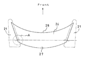
この翼は、後部トランクリッドの上面の両側部に対向して立設された一対の合成樹脂製の垂直翼21、21と、これら垂直翼21、21の対向面に形成された凹部21a内に皿小ねじ22によって固定された取付板23と、これら取付板23、23間に横架されたアルミニウムまたはアルミニウム合金からなる中空の水平翼24とから構成されたものである。
【0017】
ここで、水平翼24は、アルミニウム等の押出加工によって翼形状に成形された本体25と、この本体25の両側部に溶接によって一体に接合された側板26とからなるもので、図2に示すように、その幅寸法は、翼厚の薄い後縁27から翼厚の厚い前縁28に向けて漸次大きくなるように形成されている。そして、この水平翼24の表面は、アルマイト処理されるとともに、ブラスト等の表面粗化処理によって梨地状に形成されている。また、この水平翼24の側板26の後縁27側には、先端部にねじを有する回動軸29が立設されている。他方、側板26の幅広の前縁28側には、孔部30が穿設されている。
【0018】
一方、上記取付板23は、水平翼24の側板26よりもひと回り大きな扇形に形成されたアルミニウム板であり、水平翼24の回動軸29と対向する位置には、挿通孔31が穿設されている。そして、水平翼24は、回動軸29が滑りを良くするための樹脂ワッシャ33を介して取付板23の挿通孔31に挿通され、頭部にナット32が螺合されることにより、上記取付板23を介して垂直翼21に回動自在に設けられている。
ここで、図3に示すように、側板26の回動軸29の近傍部分26aと、取付板23の挿通孔31の近傍部分31aは、それぞれ対向する側の側板26および取付板23と平行になるようにプレス加工によって屈曲されており、これによって水平翼24の両側部における回動軸29の軸線が互いに一致することにより、水平翼24が円滑に回動し得るようになっている。
【0019】
また、水平翼23の上記孔部30と対向する側の取付板23には、上記挿通孔31を中心にした円弧状の固定部34が形成されている。この固定部34は、水平翼24の孔部(縁部)30の回動軌跡に沿って、下方から上方に向けて漸次水平翼23の側板26側に傾斜するように形成されている。これにより、図8に示すように、水平翼24が回動軸29回りに回動した場合においても、常に固定部34と水平翼24の回動側縁部との隙間が一定になるように設定されている。
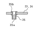
そして、この固定部34に、上下方向に向けて複数のポップナット(ナット)35が取り付けられている。
このポップナット35は、図4に示すように、内周面に雌ねじ35aが形成されており、側板26と対向する基端部35bが取付板23に穿設された孔部に加締められることにより取付板23に固定されている。
【0020】
さらに、水平翼24の中空部内には、側板26に穿設された孔部30から突出して上記ポップナット35と選択的に螺合することにより、水平翼24の迎え角を変化させて当該水平翼24を固定するためのボルト36が配設されている。
すなわち、水平翼24の下面所定位置には、ボルト36を操作するための開口部37が形成されており、この開口部37は、樹脂製のキャップ38によって塞がれるようになっている。そして、水平翼24の側板26の裏面側に、ばね鋼からなる板ばね(連結部材)39の一端部が固定されており、この板ばね39の屈曲された先端部に、孔部が穿設されている。
【0021】
この孔部は、直径が上記ボルト36のねじ山径よりも小さく、かつボルト36のねじが形成されていない首下部よりも僅かに大径に形成されている。そして、この孔部にボルト36が螺合されて、その首下部が嵌合されることにより、ボルト36は、脱落が防止された状態で、孔部30からポップボルト35に対する着脱方向に向けて変位自在に、板ばね39の先端部に取り付けられている。ちなみに、開口部37は、このボルト36の直下に形成されており、これにより開口部37から上記ボルト36の回動を操作できるようになっている。なお、ボルト36としては、一般的な頭部を有するボルトを使用してもよく、あるいはキャップボルトを使用してもよい。なお、キャップボルトを使用した場合には、開口部37から六角レンチを操作することによって、容易にボルト36の回動を行なうことができる。
そして、これらボルト36および取付板23の固定部34に配設された複数のポップナット35により、水平翼24の固定手段が構成されている。
【0022】
以上の構成からなる自動車用翼においては、開口部37のキャップ38を取り外して当該開口部37からボルト36を操作し、それまで螺合していた一のポップナット35から取り外すことにより、水平翼24は回動軸29回りに回動可能になる。そこで、上記水平翼24を所望の角度回動させて、再びボルト36を対応位置にある他のポップナット35に螺合させることにより、当該水平翼24の迎え角を容易に変更することができる。
【0023】
このような自動車用翼によれば、垂直翼21、21間に横架される水平翼24として、アルミニウムまたはアルミニウム合金製のものを使用しているので、従来の合成樹脂製のものと比較して軽量でかつ高い強度を得ることができ、よって補強材等を必要とすることなく薄肉の良好な翼形状にすることができる。加えて、その表面をアルマイト処理するとともに、さらにブラスト等によって粗化処理して梨地状にしているので、美観に優れるとともに、過多な光の反射を防止することができる。
また、水平翼24を、一の回動軸29回りに回動自在に設け、かつ開口部37から操作可能なボルト36を用いた固定手段によって、水平翼24を所定の迎え角で垂直翼21に固定しているので、極めて容易に水平翼24の迎え角を変化させることができるうえに、さらにボルト36が水平翼24の中空部内に配設されていて外観に晒されることがないために、全体として一層優れた外観を得ることができる。
【0024】
しかも、ボルト36を板ばね39に取り付けているので、手探りによって容易にボルト36を操作することができるとともに、仮に操作中にボルト36から手が外れた場合においても、当該ボルト36が脱落して行方が不明になるといった虞が無い。
また、側板26の回動軸29の近傍部分26aと、取付板23の挿通孔31の近傍部分31aとを、それぞれ対向する側の側板26および取付板23と平行になるようにプレス加工によって屈曲することにより、水平翼24の両側部における回動軸29の軸線が互いに一致させ、かつ側板26と取付板23との間に樹脂ワッシャ33を介装しているので、水平翼24を円滑に回動させることができる。
【0025】
この際に、水平翼24の幅寸法が後縁27から前縁28に向けて漸次大きくなるように形成しているのに対応して、図8に示すように、水平翼24の回動側縁部と対向する取付板23の固定部34を、縁部回動軌跡に沿って上下方向に向けて傾斜させているので、水平翼24を回動させた場合においても、固定部34と水平翼24の側板26との間の隙間を一定の保持することができる。
【0026】
以上説明したように、請求項1〜4のいずれかに記載の自動車用翼によれば、垂直翼間に横架される水平翼として、アルミニウムまたはアルミニウム合金製のものを使用しているので、従来の合成樹脂製のものと比較して軽量でかつ高い強度を得ることができ、よって補強材等を必要とすることなく薄肉の良好な翼形状にすることができるうえに、上記アルミニウム等はアルマイト処理を行なうことにより、優れた美観を得ることができるため、全体としての外観に優れる。
しかも、上記水平翼を、一の回動軸回りに回動自在に設け、かつ上記水平翼を所定の迎え角で上記垂直翼に固定する固定手段を設けているので、固定手段を解除して水平翼を回動軸回りに回動させ、再び固定手段を取り付けることにより、極めて容易に水平翼の迎え角を変化させることができるといった効果が得られる。
さらに、固定手段が位置する水平翼の回動側縁部と対向する垂直翼の固定部を、上記水平翼の迎え角を変えるべく上記前縁を下方から上方へ向けて回動させた際に、当該回動軌跡に沿って上記前縁と上記固定部との隙間が一定になるように上下方向に向けて傾斜させているので、水平翼を回動させた場合においても、固定手段が設けられた水平翼と垂直翼の固定部との間の隙間を一定に保持することができる。
【図面の簡単な説明】
【図1】本発明の一実施形態における水平翼および取付板を示す分解斜視図である。
【図2】本実施形態の平面図である。
【図3】図3のA部を示す拡大断面図である。
【図4】図1の取付板のボルト孔を示す断面図である。
【図5】図1のボルトとその連結部材を示す斜視図である。
【図6】図5の連結部材の取付状態を示す断面図である。
【図7】垂直翼と水平翼との取付状態を示す分解斜視図である。
【図8】垂直翼と水平翼との位置関係を示す背面視図である。
【図9】従来の自動車用翼を示す斜視図である。
【図10】図9の水平翼と垂直翼との取付部分を示す背面視図である。
【図11】従来の他の自動車用翼を示す背面視図である。
【符号の説明】
21 垂直翼
23 取付板
24 水平翼
27 後縁
28 前縁
29 回動軸
34 固定部
35 ポップナット(ナット)
36 ボルト
37 開口部
38 キャップ
39 板ばね(連結部材)[0001]
BACKGROUND OF THE INVENTION
The present invention relates to a wing attached to the rear upper surface of various automobiles such as passenger cars.
[0002]
[Prior art]
In recent years, not only racing four-wheeled vehicles but also general passenger vehicles have been developed in which a wing is mounted on a rear trunk lid.
This wing uses a horizontal wing that is thicker at the leading edge and thinner at the trailing edge. By closely contacting the traveling surface, energy loss is minimized to improve fuel efficiency and to realize stable traveling. Incidentally, the general passenger car described above also has a decorative purpose in appearance.
[0003]
9 and 10 show a wing 3 mounted on a
The wing 3 is composed of a pair of vertical wings 4, 4 that are erected on opposite sides of the
[0004]
In such a wing 3, there is a demand for appropriately changing the angle of attack of the
[0005]
[Problems to be solved by the invention]
By the way, in such a conventional automobile wing 3, when the angle of attack of the
Further, since the
[0006]
Therefore, as shown in FIG. 11, an automobile wing 10 having a structure in which the central portion of the
However, in the wing 10 for an automobile, the reinforcing
In addition, since it is difficult to freely change the height of the reinforcing
[0007]
The present invention has been made to effectively solve the problems of the above-described conventional automobile wings, and has a horizontal wing that is lightweight and excellent in strength, and thus has a thin wall thickness without requiring a reinforcing material or the like. An object of the present invention is to provide a wing for an automobile that can have a good wing shape and is excellent in appearance and can easily change the angle of attack of a horizontal wing.
[0008]
[Means for Solving the Problems]
According to a first aspect of the present invention, there is provided a wing for an automobile according to the present invention, comprising: a pair of vertical wings arranged opposite to both sides of a rear upper surface of an automobile; and aluminum or an aluminum alloy horizontally mounted between the vertical wings. The horizontal wing is formed such that the width dimension gradually increases from the rear edge toward the front edge, and the angle of attack is variable. And a fixing means for fixing the horizontal wing to the vertical wing at a predetermined angle of attack between the leading edge and the vertical wing. The fixing portion of the vertical wing facing the front edge provided with the fixing means is rotated when the front edge is rotated upward from below to change the angle of attack of the horizontal wing. from below so that the clearance between the leading edge and the fixing unit becomes constant Toward towards it gradually which is characterized in that it is formed to be inclined to the horizontal wing side.
[0010]
According to a second aspect of the present invention, the fixing means according to the first aspect is provided with a bolt projecting from the hollow portion side of the horizontal wing to the vertical wing side, and a plurality of locations facing the vertical wing in the vertical direction. The horizontal wing is provided with an opening for operating the bolt in the hollow portion.
Further, the invention according to claim 3, said bolts, are those wherein the disposed within horizontal wing is attached to the connecting member can be displaced in the detachable direction with respect to the nut, also claim 4 the invention according to is one in which at least the upper surface of the horizontal blade according to any one of claims 1 to 3, characterized in that it is formed on the textured by surface roughening treatment.
[0011]
In the automobile wing according to any one of claims 1 to 4 , since the horizontal wing horizontally mounted between the vertical wings is made of aluminum or aluminum alloy, it is made of a conventional synthetic resin. In addition to being able to obtain light weight and high strength compared to the above, it is possible to obtain a thin wing shape without the need for reinforcing materials, etc. Since an excellent aesthetic appearance can be obtained, the overall appearance is also excellent.
In addition, since the horizontal wing is provided so as to be rotatable about one rotation axis and the horizontal wing is fixed to the vertical wing at a predetermined angle of attack, the fixing means is released. The angle of attack of the horizontal blade can be changed very easily by rotating the horizontal blade around the rotation axis and attaching the fixing means again.
[0012]
By the way, when the horizontal wing is rotated about the rotation axis to change the angle of attack, the horizontal wing has a constant width dimension from the leading edge to the trailing edge of the wing. The pivoting edge portion is vertically displaced in the vertical direction. However, when the horizontal blade is formed so that the width dimension of the horizontal blade gradually increases from one of the front edge and the rear edge to the other, when the horizontal blade is rotated about the rotation axis, The rotation trajectory of the edge on the rotation side is displaced in the direction away from the vertical wing side or the vertical wing.
In this regard, in the first aspect of the invention, the vertical wing facing the turning side edge of the horizontal wing on which the fixing means is located is inclined in the vertical direction along the edge turning locus. because there can be held horizontal wings when is rotated also, the gap between the horizontal wing and a vertical wing fixing means is provided constant.
[0013]
According to the second aspect of the present invention, the fixing means for fixing the horizontal wing to the vertical wing includes a bolt projecting from the hollow portion side of the horizontal wing to the vertical wing side, and a plurality of locations directed vertically to the vertical wing. The bolt is not exposed to the external appearance, so that the overall appearance is further improved.
[0014]
At this time, when changing the angle of attack of the horizontal wing, it is necessary to operate the bolt in the hollow portion that is difficult to see from the opening of the horizontal wing.
In this regard, according to the third aspect of the invention, the bolt is attached to a connecting member that is disposed in the horizontal wing and is displaceable in the attaching / detaching direction with respect to the nut. In addition, even if the hand is removed from the bolt during operation, there is no risk of losing sight of the bolt.
[0015]
Furthermore, as described above, since the horizontal wing is made of aluminum or an aluminum alloy, an excellent aesthetic appearance can be obtained by performing the surface alumite treatment. Depending on conditions such as the structure of the vehicle on which the wing is mounted and the mounting position of the horizontal wing, the surface of the horizontal wing may reflect an unnecessarily large amount of light. Therefore, as in the invention described in claim 4 , at least the upper surface of the horizontal wing is further roughened by blasting or the like to form a satin finish, thereby preventing excessive light reflection and more excellent. It is possible to get an aesthetic.
[0016]
DETAILED DESCRIPTION OF THE INVENTION
1 to 8 show an embodiment of an automobile wing according to the present invention mounted on a rear trunk lid of an automobile, similar to that shown in FIG.
The wings are provided in a pair of synthetic resin
[0017]
Here, the
[0018]
On the other hand, the mounting
Here, as shown in FIG. 3, the
[0019]
Further, an
A plurality of pop nuts (nuts) 35 are attached to the fixed
As shown in FIG. 4, the
[0020]
Further, the
That is, an
[0021]
The hole is formed to have a diameter that is smaller than the screw thread diameter of the
The
[0022]
In the automotive wing having the above-described configuration, the
[0023]
According to such an automobile wing, since the
Further, the
[0024]
Moreover, since the
In addition, a
[0025]
At this time, the width of the
[0026]
As described above, according to the automotive wing according to any one of claims 1 to 4, since the horizontal wing horizontally mounted between the vertical wings is made of aluminum or aluminum alloy, Compared to conventional synthetic resin products, it is lightweight and has high strength, so it can be made into a thin wing shape without the need for reinforcing materials, etc. By performing alumite treatment, an excellent aesthetic appearance can be obtained, so that the overall appearance is excellent.
In addition, since the horizontal wing is provided so as to be rotatable about one rotation axis and the horizontal wing is fixed to the vertical wing at a predetermined angle of attack, the fixing means is released. By rotating the horizontal wing about the rotation axis and attaching the fixing means again, it is possible to obtain an effect that the angle of attack of the horizontal wing can be changed very easily.
Further, when the front blade is rotated from the lower side to the upper side in order to change the angle of attack of the horizontal blade , the fixed portion of the vertical blade that faces the rotating side edge of the horizontal blade where the fixing means is located. In addition , the fixing means is provided even when the horizontal blade is rotated because the gap between the front edge and the fixing portion is inclined so as to be constant along the rotation trajectory. The gap between the horizontal wing and the fixed portion of the vertical wing can be kept constant.
[Brief description of the drawings]
FIG. 1 is an exploded perspective view showing a horizontal blade and a mounting plate in an embodiment of the present invention.
FIG. 2 is a plan view of the present embodiment.
FIG. 3 is an enlarged cross-sectional view showing a portion A of FIG.
4 is a cross-sectional view showing a bolt hole in the mounting plate of FIG. 1;
5 is a perspective view showing the bolt of FIG. 1 and its connecting member. FIG.
6 is a cross-sectional view showing an attachment state of the connecting member of FIG. 5;
FIG. 7 is an exploded perspective view showing a mounting state of the vertical wing and the horizontal wing.
FIG. 8 is a rear view showing the positional relationship between the vertical wing and the horizontal wing.
FIG. 9 is a perspective view showing a conventional automobile wing.
10 is a rear view showing a mounting portion between the horizontal wing and the vertical wing of FIG. 9; FIG.
FIG. 11 is a rear view showing another conventional automobile wing.
[Explanation of symbols]
21
36
Claims (4)
Priority Applications (1)
| Application Number | Priority Date | Filing Date | Title |
|---|---|---|---|
| JP06211398A JP3906552B2 (en) | 1998-02-26 | 1998-02-26 | Automotive wings |
Applications Claiming Priority (1)
| Application Number | Priority Date | Filing Date | Title |
|---|---|---|---|
| JP06211398A JP3906552B2 (en) | 1998-02-26 | 1998-02-26 | Automotive wings |
Publications (2)
| Publication Number | Publication Date |
|---|---|
| JPH11245851A JPH11245851A (en) | 1999-09-14 |
| JP3906552B2 true JP3906552B2 (en) | 2007-04-18 |
Family
ID=13190688
Family Applications (1)
| Application Number | Title | Priority Date | Filing Date |
|---|---|---|---|
| JP06211398A Expired - Fee Related JP3906552B2 (en) | 1998-02-26 | 1998-02-26 | Automotive wings |
Country Status (1)
| Country | Link |
|---|---|
| JP (1) | JP3906552B2 (en) |
-
1998
- 1998-02-26 JP JP06211398A patent/JP3906552B2/en not_active Expired - Fee Related
Also Published As
| Publication number | Publication date |
|---|---|
| JPH11245851A (en) | 1999-09-14 |
Similar Documents
| Publication | Publication Date | Title |
|---|---|---|
| US5214971A (en) | Angular adjustment mechanism | |
| US8579361B2 (en) | Vehicle undercover | |
| US4989290A (en) | Wiper arm equipment | |
| JP3259859B2 (en) | Cutting knife | |
| CA2516381A1 (en) | Running board | |
| US20060123592A1 (en) | Adjustable hinge for a motor vehicle | |
| JP3906552B2 (en) | Automotive wings | |
| JP2019516034A (en) | Adjustable hinge assembly | |
| JPH0730842Y2 (en) | Closed handle device | |
| US5669760A (en) | Ceiling fan with integral blade and neck | |
| JPH036494Y2 (en) | ||
| CN222373011U (en) | Tail wing surface difference adjusting structure, automobile tail wing and automobile | |
| US5144858A (en) | Device for limiting rotary movement | |
| JP2000103371A (en) | Wing movable rear spoiler of automobile | |
| CN222572413U (en) | Turbulence blade for a vehicle diffuser, vehicle diffuser and vehicle | |
| CN219969878U (en) | Electric motor car fender structure | |
| CN222731334U (en) | Hinges, doors and vehicles | |
| CN219948050U (en) | Rotary clothes and hat hook for passenger car | |
| CN205800747U (en) | Full automatic glass car door and be mounted with the automobile of this car door | |
| CN213323459U (en) | Bicycle reflector lamp | |
| CN220384714U (en) | Function sofa pullswitch | |
| CN107878282B (en) | Flip-up car seat basin | |
| CN212766116U (en) | A kind of installation structure of wiper arm | |
| CN213534603U (en) | Automobile front wheel arch structure convenient to locate | |
| CN218536583U (en) | Combination switch structure of automobile |
Legal Events
| Date | Code | Title | Description |
|---|---|---|---|
| A977 | Report on retrieval |
Free format text: JAPANESE INTERMEDIATE CODE: A971007 Effective date: 20051228 |
|
| A131 | Notification of reasons for refusal |
Free format text: JAPANESE INTERMEDIATE CODE: A131 Effective date: 20060207 |
|
| A521 | Written amendment |
Free format text: JAPANESE INTERMEDIATE CODE: A523 Effective date: 20060403 |
|
| A131 | Notification of reasons for refusal |
Free format text: JAPANESE INTERMEDIATE CODE: A131 Effective date: 20060829 |
|
| A521 | Written amendment |
Free format text: JAPANESE INTERMEDIATE CODE: A523 Effective date: 20061013 |
|
| TRDD | Decision of grant or rejection written | ||
| A01 | Written decision to grant a patent or to grant a registration (utility model) |
Free format text: JAPANESE INTERMEDIATE CODE: A01 Effective date: 20061226 |
|
| A61 | First payment of annual fees (during grant procedure) |
Free format text: JAPANESE INTERMEDIATE CODE: A61 Effective date: 20070108 |
|
| R150 | Certificate of patent or registration of utility model |
Free format text: JAPANESE INTERMEDIATE CODE: R150 |
|
| FPAY | Renewal fee payment (event date is renewal date of database) |
Free format text: PAYMENT UNTIL: 20110126 Year of fee payment: 4 |
|
| LAPS | Cancellation because of no payment of annual fees |