JP3905723B2 - Fishing lure - Google Patents
Fishing lure Download PDFInfo
- Publication number
- JP3905723B2 JP3905723B2 JP2001163195A JP2001163195A JP3905723B2 JP 3905723 B2 JP3905723 B2 JP 3905723B2 JP 2001163195 A JP2001163195 A JP 2001163195A JP 2001163195 A JP2001163195 A JP 2001163195A JP 3905723 B2 JP3905723 B2 JP 3905723B2
- Authority
- JP
- Japan
- Prior art keywords
- guide passage
- lure
- rear direction
- fishing
- right direction
- Prior art date
- Legal status (The legal status is an assumption and is not a legal conclusion. Google has not performed a legal analysis and makes no representation as to the accuracy of the status listed.)
- Expired - Fee Related
Links
- 230000005012 migration Effects 0.000 claims description 10
- 238000013508 migration Methods 0.000 claims description 10
- 238000005266 casting Methods 0.000 claims description 6
- 229910000831 Steel Inorganic materials 0.000 description 22
- 239000010959 steel Substances 0.000 description 22
- 241000251468 Actinopterygii Species 0.000 description 10
- 230000005484 gravity Effects 0.000 description 7
- 230000000694 effects Effects 0.000 description 3
- XEEYBQQBJWHFJM-UHFFFAOYSA-N Iron Chemical compound [Fe] XEEYBQQBJWHFJM-UHFFFAOYSA-N 0.000 description 2
- 210000001015 abdomen Anatomy 0.000 description 2
- 210000003128 head Anatomy 0.000 description 2
- 210000001061 forehead Anatomy 0.000 description 1
- 229910052742 iron Inorganic materials 0.000 description 1
- 239000011133 lead Substances 0.000 description 1
- 239000000463 material Substances 0.000 description 1
- 230000000630 rising effect Effects 0.000 description 1
- 238000005096 rolling process Methods 0.000 description 1
- 230000009182 swimming Effects 0.000 description 1
- 229920003002 synthetic resin Polymers 0.000 description 1
- 239000000057 synthetic resin Substances 0.000 description 1
- WFKWXMTUELFFGS-UHFFFAOYSA-N tungsten Chemical compound [W] WFKWXMTUELFFGS-UHFFFAOYSA-N 0.000 description 1
- 229910052721 tungsten Inorganic materials 0.000 description 1
- 239000010937 tungsten Substances 0.000 description 1
- XLYOFNOQVPJJNP-UHFFFAOYSA-N water Substances O XLYOFNOQVPJJNP-UHFFFAOYSA-N 0.000 description 1
- 238000003466 welding Methods 0.000 description 1
Images
Description
【0001】
【発明の属する技術分野】
本発明は、ルアー本体内に重錘体を前後方向へ移動可能に仕込んた魚釣用ルアーに関する。
【0002】
【従来の技術】
従来から、魚釣用ルアーには、遠投が可能であること、及び安定した良好な泳動をすることが求められている。そのため、ルアー本体の内部に球状の重錘体を前後方向へ移動可能に仕込んで、キャスティング時にはルアー後方へ重錘体を移動させて遠投性を上げ、ルアーの泳動時にはルアー前方へ重錘体を移動させ、そこに保持するようにしてルアー本体の前方下部に重心を定めることにより、ルアーの姿勢を安定させると共に上記重心を中心として尾を振る規則的な泳動をするようにした魚釣用ルアーが提案されていた。
【0003】
このような魚釣用ルアーとして、たとえば、実公平3−15021号公報には前後方向へ直線的に延びた中空のガイド通路をルアー本体の内部に形成し、この中空のガイド通路に重錘体を収納し、球状の重錘体が前後方向に移動可能にしたものが提案されており、また、実公平7−3889号公報にはルアー本体の内部空間で前後方向へ延在する直線的な線材に重錘体をスライド自在に被嵌し、重錘体が前後方向に移動可能にしたルアーが提案されている。
【0004】
【発明が解決しようとする課題】
上述したような魚釣用ルアーではいずれも着水後の泳動時に上記球状の重錘体がルアー本体の前方下部の位置で保持されるため、重心位置がルアー本体の前方下部に定まり、ルアー本体は安定した姿勢を保ちながら常に規則的な泳動をするようになる。しかし、このように規則的に泳動する単純な動きばかりでは魚がルアーの動きに慣れてしまい、興味を示さなくなってしまうという問題があった。
【0005】
本発明は上記課題に着目してなされたもので、その目的とするところは、キャスティング時の遠投性を確保しながら、泳動時には魚が興味を示す動きを与え、魚を誘う効果の向上を図った魚釣用ルアーを提供することにある。
【0006】
【課題を解決するための手段】
請求項1に係る発明は、ルアー本体内に重錘体を前後方向へ移動可能に仕込み、キャスティング時には重錘体をルアー本体の後方部位に移動させ、ルアーの泳動時には重錘体をルアー本体の前方部位に移動させるようにした魚釣用ルアーにおいて、
ルアー本体に、前後方向へ延びて形成され、重錘体を前後方向へ移動可能に収容する前後方向移動用ガイド通路と、この前後方向移動用ガイド通路の前端に連通してルアー本体の左右方向へ延びて形成され、泳動時、重錘体を左右方向へ移動可能に収容する左右方向移動用ガイド通路とを設けたものである。
【0007】
請求項2に係る発明は、左右方向移動用ガイド通路は、ルアーの泳動姿勢時において上記前後方向移動用ガイド通路の前端よりも低い位置に形成されたことを特徴とする請求項1に記載の魚釣用ルアーである。
【0008】
請求項3に係る発明は、左右方向移動用ガイド通路は、その中央部分が前後方向移動用ガイド通路の前端に連通して形成され、その左右方向移動用ガイド通路は中央部分が低く、左右部分の路面が中央部分より立ち上がる傾斜面に形成したことを特徴とする請求項1または請求項2に記載の魚釣用ルアーである。
【0009】
請求項4に係る発明は、前後方向移動用ガイド通路の前端に続く左右方向移動用ガイド通路の部分に誘導壁を形成し、ルアーを釣糸に吊り下げたとき、誘導壁を経て重錘体を左右方向移動用ガイド通路内から前後方向移動用ガイド通路内に誘導するようにしたことを特徴とする請求項1、請求項2または請求項3に記載の魚釣用ルアーである。
【0010】
請求項5に係る発明は、重錘体は、質量が異なる複数のものを設けたことを特徴とする請求項1、請求項2、請求項3または請求項4に記載の魚釣用ルアーである。
【0011】
【発明の実施の形態】
以下、図面を参照しながら本発明の実施の形態に係る魚釣用ルアーについて説明する。
【0012】
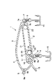
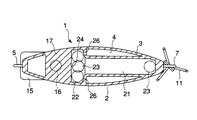
本実施形態の魚釣用ルアー1は外形が対象魚の餌、たとえば小魚に似るように成形されたルアー本体2を備えている。ルアー本体2は左右に縦割りにされてなる一対のピースを合成樹脂等により成形し、この一対のピースを背中合わせにして接着又は溶着等の適当な手段により両者を一体化して作られている。ルアー本体2は外殻3内に空間部4を形成してなり、この空間部4はルアー本体2の略全長にわたって形成されると共にルアー本体2の外殻3によって完全に密閉されている。
【0013】
このルアー本体2の頭頂部には、リング形状部5aを有する釣糸止着部5が設けられており、このリング形状部5aはルアー本体2から突き出している。釣糸止着部5のリング形状部5aには図示しない釣糸が結束されるようになっている。上記ルアー本体2の腹部における前方部位にはリング形状部6aを有する第1の釣針止着部6が設けられおり、このリング形状部6aはルアー本体2から突き出している。上記ルアー本体2の最尾部にはリング形状部7aを有する第2の釣針止着部7が設けられており、このリング形状部7aはルアー本体2から突き出している。上記各釣針止着部6,7のリング形状部6a,7aにはスプリットリング8,9を介して釣針10,11が吊り下げる状態で係着されている。釣糸止着部5および各釣針止着部6,7の支持杆5b,6b,7b,はいずれもルアー本体2の一対のピースを背中合わせに接合して一体化する際にそのピースの間に挟み込んで固着されている。また、支持杆5b,6b,7b,を固定するルアー本体2の部分は他の外殻3の厚みよりも厚い壁部として形成されている。
【0014】
ルアー本体2の頭頂部のやや下方に位置する喉部には前方が下がる向きで傾斜したリップ状の抵抗板15が一体に突設されている。抵抗板15は上述した第1の釣針止着部6の固定位置よりも前方に位置して設けられている。
【0015】
ルアー本体2の腹の前方部位には固定重錘体16が設けられている。固定重錘体16はルアー本体2の外殻3の壁部を内側の空間部4側に厚く形成した台部17に埋め込んで設置されている。この固定重錘体16は図1に示すように抵抗板15を取り付ける位置と上記第1の釣針止着部6の支持杆6bを取着する部分との間に位置して設置されている。
【0016】
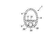
ルアー本体2の内部には前後方向へ略直線的に延びて形成された前後方向移動用ガイド通路21と、この前後方向移動用ガイド通路21の前端に連通してルアー本体2の左右方向へ延びて形成された左右方向移動用ガイド通路22が設けられている。前後方向移動用ガイド通路21は重錘体としての鋼球23を前後方向へ移動可能に収容する第1の手段を構成している。また、左右方向移動用ガイド通路22は鋼球23を左右方向へ移動可能に収容する第2の手段を構成している。
【0017】
左右方向移動用ガイド通路22はその中間中央部を前後方向移動用ガイド通路21の前端に連通してルアー本体2の左右方向へ均等に延び、平面からみて、前後方向移動用ガイド通路21のに略直角で左右対称に形成されている。そして、鋼球23は前後方向移動用ガイド通路21と左右方向移動用ガイド通路22にわたり移動が可能である。
【0018】
上記球状の鋼球23は鉛やタングステンや鉄系の比重の比較的大きい材料により球状に形成されている。上記ガイド通路21,22はこれに収容する球状の鋼球23が転がって移動できるように左右の幅と上下の幅が鋼球23の直径よりも僅かに大きくなるように壁面が形成されている。
【0019】
前後方向移動用ガイド通路21は図1に示すように、路面の前方側が低くなるように傾斜して配置され、その前端に左右方向移動用ガイド通路22の中間部側部が連通している。従って、泳動時、鋼球23は前後方向移動用ガイド通路21内を転がって左右方向移動用ガイド通路22に入り込むことができる。
【0020】
前後方向移動用ガイド通路21と左右方向移動用ガイド通路22とは図2に示すように平面的に見て略Tの字状に配置される。つまり、前後方向移動用ガイド通路21に対して左右方向移動用ガイド通路22は略直角に配置されている。
【0021】
前後方向移動用ガイド通路21の前端に対向する左右方向移動用ガイド通路22の側壁は前後方向移動用ガイド通路21内を転がってきた鋼球23を突き当てる突当て部24を形成する。突当て部24は前後方向移動用ガイド通路21内を転がってきた鋼球23を受け止め、左右方向移動用ガイド通路22内に落とし込むガイド手段を構成している。
【0022】
左右方向移動用ガイド通路22は図1に示すように、前後方向移動用ガイド通路21の前端よりも低い段部25として形成され、段部25には前後方向移動用ガイド通路21内を転がってきた鋼球23が落ち込むようになっている。また、左右方向移動用ガイド通路22は図3に示すように路面中央部分が最も低くなるように左右が傾斜する路面として形成されている。具体的には、左右方向移動用ガイド通路22のガイド路面は中央部位が最も低い、いわば円弧部を下方に向けるようにした半円形状に形成されている。つまり、左右方向移動用ガイド通路22は中央部が最も低くなるように左右方向に傾斜面が形成されている。
【0023】
また、上記前後方向移動用ガイド通路21の前端から左右に続く左右方向移動用ガイド通路22の左右の後端壁面部分はいずれも前後方向移動用ガイド通路21側に向かって次第に後方へ傾斜した誘導壁26が形成されている。また、図1に示すように段部25にも同じような誘導壁26が形成されている。
【0024】
次に、上記構成の魚釣用ルアー1の作用について説明する。まず、竿先のガイドよりわずかに釣糸を出した状態でルアー1を垂下させる。この状態ではルアー1は頭頂部を上方に向けて吊り下がる姿勢となるため、仮に左右方向移動用ガイド通路22内にあった鋼球23は上記誘導壁26,27に誘導されて前後方向移動用ガイド通路21の前端からその前後方向移動用ガイド通路21内に転がって入り込み、前後方向移動用ガイド通路21の後端まで移動する。従って、ルアー1を吊り下させた状態では鋼球23は前後方向移動用ガイド通路21の後端(下端)に位置する。
【0025】
次に、釣竿を勢いよく振って上記ルアー1をキャスティングする。この時、上記鋼球23は遠心力により上記前後方向移動用ガイド通路21の後端部に押し当たって保持され、かつルアー1は飛行方向の前方へ最尾部を向けた逆向きの安定した姿勢で飛行する。そして、所定のポイントにキャストして着水する。
【0026】
ルアー1が着水すると、上記固定重錘体16等のルアー全体の重さのバランスによりルアー本体2の前頭部が前傾する姿勢となる。これによって上記前後方向移動用ガイド通路21も図1に示すように前方が下がった向きで傾斜する。このため、上記鋼球23は転がりながら前方へ略直線的に移動する。そして、突当て部24に当たって左右方向移動用ガイド通路22内に落ち込み、その左右方向移動用ガイド通路22に収容される。
【0027】
そして、リールに釣り糸を巻き上げて、ルアー1をリトリーブしていくと、抵抗板15が水の抵抗を受けて、ルアー本体2の前頭部が前傾する姿勢で泳動する。この泳動時、鋼球23は左右方向移動用ガイド通路22内に位置しており、ルアー本体2の重心がルアー1の前方下部に定まる。このため、ルアー1は安定した姿勢を保ちながら重心位置を中心に尾を振って魚が泳ぐような動きをする。特に、左右方向移動用ガイド通路22が、リップ状の抵抗板15よりも後方に位置した第1の釣針止着部6や固定重錘体16が設けられた重心位置に一致またはその近傍に配置されているので、泳動するルアー1の動作の安定性が増す。
【0028】
一方、左右方向移動用ガイド通路22内に位置した鋼球23は上述したルアー1の尾振り運動に伴って左右方向移動用ガイド通路22内を左右に移動することになる。この左右に移動する鋼球23の反動でルアー本体2には単に尾を振って動く規則的な動きに加えて、複雑または突飛な動きが加わる。その不規則に変化する動き、時にはオーバーな動作によって、ルアー1にはリアル感が生じ、または慣れのない動きが起こる。このため、魚はルアーの動きに興味を示し続ける。また、ルアー1をリトリーブする操作に変化を与えれば、上記動作が助長され、または動きの変化の態様を意図的に多様化することができる。
【0029】
また、左右方向移動用ガイド通路22はその左右部分が傾斜しているため、鋼球23は左右方向へ直線的に動くのではなく曲がるように揺動する。このため、鋼球23が左右方向に一直線に移動する場合に比べて、反動の向きが遂時変化する。このように移動する鋼球23の反作用による変動が複雑になるため、ルアー1に与える動きもより複雑になる。その結果、魚を誘引する効果が、より一層高まる。
【0030】
また、左右方向移動用ガイド通路22は前後方向移動用ガイド通路21の前端よりも低い段部25を形成しているため、鋼球23が左右方向に移動する際にもその左右方向移動用ガイド通路22内に留まり易い。
【0031】
なお、本発明は、前述した実施の形態のものに限定されるものではない。例えば、重錘体として球体のものでななく、いわゆるコロ体状のもの等の転動できる形やガイド通路を滑動できるものでもよい。
【0032】
また、重錘体の個数は1個でなくとも複数のものであってもよく、その場合、移動し易い2〜3個ぐらいが望ましい。また、複数の重錘体を設ける場合はそれぞれ異なる大きさまたは重さのものであってもよい。このようにすることで、ルアーにより複雑な動きをさせることができる。
【0033】
また、各ガイド通路は、重錘体を収容し、その移動させる方向にガイドできるものであれば、全面が壁の通路の場合に限らず、線材や枠部材などで通路を形成する場合であってもよい。
【0034】
また、左右方向移動用ガイド通路は、ルアー本体の空間内に連通するように開放し、重錘体が通路に戻り得るようにするならば、左右方向移動用ガイド通路からルアー本体の空間内に一時的に重錘体が入り込み得るようにしてもよい。
【0035】
前後方向移動用ガイド通路は重錘体を略前後方向に移動させることができればよく、左右方向移動用ガイド通路は、重錘体を略左右方向に移動させることができればよいものである。
【0036】
本発明において、前後方向とか左右方向とは完全な直線の場合に限らず、多少曲がったり屈曲したりするものでもよい。また、前述した実施形態では、平面的に見て、前後方向移動用ガイド通路に対して左右方向移動用ガイド通路22が直角に配置されていたが、前後方向移動用ガイド通路に対して左右方向移動用ガイド通路22が多少傾くものでもよいし、左右方向移動用ガイド通路の左右側方部分が斜め前方に伸び、前後方向移動用ガイド通路と左右方向移動用ガイド通路が略Yの字状に配置されるものであってもよい。
【0037】
【発明の効果】
以上のように本発明によれば、キャスティング時にはルアーの姿勢が安定し、比較的簡単に遠投することが可能となり、泳動時には不規則な動きをするため、魚を誘う効果が向上する。
【図面の簡単な説明】
【図1】本発明の一実施の形態に係る魚釣用ルアーの側面断面図。
【図2】上記魚釣用ルアーの平面断面図。
【図3】上記魚釣用ルアーの内部に形成された通路を示す横断面図。
【符号の説明】
1…魚釣用ルアー
2…ルアー本体
15…抵抗板
21…前後方向移動用ガイド通路
22…左右方向移動用ガイド通路
23…鋼球
24…突当て部
25…段部
26…誘導壁
27…誘導壁[0001]
BACKGROUND OF THE INVENTION
The present invention relates to a fishing lure in which a weight body is loaded in a lure body so as to be movable in the front-rear direction.
[0002]
[Prior art]
2. Description of the Related Art Conventionally, fishing lures are required to be capable of long throwing and stable and good migration. For this reason, a spherical weight is placed inside the lure body so that it can move in the front-rear direction, and when casting, the weight is moved to the rear of the lure to increase the long throwing property. For fishing that stabilizes the posture of the lure and moves the tail with the center of gravity as the center, by setting the center of gravity at the front lower part of the lure body so that it is held there A lure was proposed.
[0003]
As such a fishing lure, for example, in Japanese Utility Model Publication No. 3-15021, a hollow guide passage extending linearly in the front-rear direction is formed inside the lure body, and a weight body is provided in the hollow guide passage. In which a spherical weight body is movable in the front-rear direction, and Japanese Utility Model Publication No. 7-3889 discloses a linear extension extending in the front-rear direction in the inner space of the lure body. A lure has been proposed in which a weight body is slidably fitted to a wire, and the weight body is movable in the front-rear direction.
[0004]
[Problems to be solved by the invention]
In any of the fishing lures described above, the spherical weight body is held at the lower front position of the lure body during migration after landing, so that the center of gravity position is determined at the lower front part of the lure body. Always moves regularly while maintaining a stable posture. However, there was a problem that the simple movement of migrating regularly in this way caused the fish to get used to the movement of the lure and showed no interest.
[0005]
The present invention has been made by paying attention to the above-mentioned problems, and its purpose is to improve the effect of inviting the fish by giving a movement that interests the fish at the time of migration while ensuring the long throwing property at the time of casting. It is to provide a fishing lure.
[0006]
[Means for Solving the Problems]
According to the first aspect of the present invention, the weight body is loaded into the lure body so as to be movable in the front-rear direction, the weight body is moved to the rear portion of the lure body during casting, and the weight body is moved to the lure body during the lure migration. In fishing lures that are moved to the front part,
The luer body extends in the front-rear direction and is formed to extend in the front-rear direction and accommodates the weight body so as to be movable in the front-rear direction, and communicates with the front end of the front-rear direction movement guide path in the left-right direction of the luer body. And a guide passage for moving in the left-right direction that accommodates the weight body so as to be movable in the left-right direction during migration.
[0007]
The invention according to
[0008]
According to a third aspect of the present invention, the guide section for moving in the left-right direction is formed such that a central portion thereof communicates with the front end of the guide passage for moving in the front-rear direction. The fishing lure according to
[0009]
According to a fourth aspect of the present invention, when a guide wall is formed at a portion of the guide passage for the left-right direction movement that follows the front end of the guide passage for the front-rear direction movement, and the lure is suspended from the fishing line, the weight body is passed through the guide wall. The fishing lure according to
[0010]
The invention according to
[0011]
DETAILED DESCRIPTION OF THE INVENTION
Hereinafter, a fishing lure according to an embodiment of the present invention will be described with reference to the drawings.
[0012]
The fishing lure 1 of the present embodiment includes a
[0013]
A fishing
[0014]
A lip-
[0015]
A fixed
[0016]
A longitudinally moving
[0017]
The
[0018]
The
[0019]
As shown in FIG. 1, the front-rear direction moving
[0020]
The front-rear direction moving
[0021]
The side wall of the lateral
[0022]
As shown in FIG. 1, the left / right
[0023]
In addition, the left and right rear end wall portions of the left-right
[0024]
Next, the operation of the fishing lure 1 having the above configuration will be described. First, the lure 1 is drooped in a state where the fishing line is slightly pulled out from the guide at the tip of the hook. In this state, since the lure 1 is hung with the top of the head facing upward, the
[0025]
Next, the lure 1 is cast by shaking the fishing rod vigorously. At this time, the
[0026]
When the lure 1 lands, the forehead of the
[0027]
When the fishing line is wound on the reel and the lure 1 is retrieved, the
[0028]
On the other hand, the
[0029]
Further, since the left and right portions of the
[0030]
Further, since the
[0031]
The present invention is not limited to the embodiment described above. For example, the weight body is not limited to a spherical body, but may be a so-called roller body or the like that can roll and slide in a guide passage.
[0032]
Further, the number of weight bodies may not be one but may be plural, and in that case, it is desirable that the number of the weight bodies be two or three that are easy to move. Further, when a plurality of weight bodies are provided, they may have different sizes or weights. By doing this, it is possible to make the lure perform a complicated movement.
[0033]
Further, each guide passage is not limited to the case where the entire surface is a wall passage as long as the weight body is accommodated and can be guided in the moving direction, and the passage is formed by a wire or a frame member. May be.
[0034]
Further, if the guide passage for lateral movement is opened so as to communicate with the space of the luer body and the weight body can be returned to the passage, the guide passage for lateral movement can enter the space of the lure body. You may make it possible for a weight body to enter temporarily.
[0035]
The forward / backward movement guide path only needs to move the weight body substantially in the front / rear direction, and the left / right movement guide path only needs to move the weight body substantially in the left / right direction.
[0036]
In the present invention, the front-rear direction and the left-right direction are not limited to a perfect straight line, and may be slightly bent or bent. In the above-described embodiment, the horizontal
[0037]
【The invention's effect】
As described above, according to the present invention, the posture of the lure is stable during casting, and it is possible to perform a long-distance casting relatively easily.
[Brief description of the drawings]
FIG. 1 is a side sectional view of a fishing lure according to an embodiment of the present invention.
FIG. 2 is a plan sectional view of the fishing lure.
FIG. 3 is a cross-sectional view showing a passage formed inside the fishing lure.
[Explanation of symbols]
DESCRIPTION OF SYMBOLS 1 ...
Claims (5)
ルアー本体に、前後方向へ延びて形成され、重錘体を前後方向へ移動可能に収容する前後方向移動用ガイド通路と、この前後方向移動用ガイド通路の前端に連通してルアー本体の左右方向へ延びて形成され、泳動時、重錘体を左右方向へ移動可能に収容する左右方向移動用ガイド通路とを設けたことを特徴とする魚釣用ルアー。The weight body is loaded into the lure body so that it can be moved in the front-rear direction, the weight body is moved to the rear part of the lure body during casting, and the weight body is moved to the front part of the lure body during lure migration. In fishing lures,
The luer body extends in the front-rear direction and is formed to extend in the front-rear direction and accommodates the weight body so as to be movable in the front-rear direction, and communicates with the front end of the front-rear direction movement guide path in the left-right direction of the luer body. A fishing lure characterized in that it is provided with a left and right direction moving guide passage that is formed so as to extend so as to move the weight body in the left and right direction during migration.
Priority Applications (1)
| Application Number | Priority Date | Filing Date | Title |
|---|---|---|---|
| JP2001163195A JP3905723B2 (en) | 2001-05-30 | 2001-05-30 | Fishing lure |
Applications Claiming Priority (1)
| Application Number | Priority Date | Filing Date | Title |
|---|---|---|---|
| JP2001163195A JP3905723B2 (en) | 2001-05-30 | 2001-05-30 | Fishing lure |
Publications (2)
| Publication Number | Publication Date |
|---|---|
| JP2002354962A JP2002354962A (en) | 2002-12-10 |
| JP3905723B2 true JP3905723B2 (en) | 2007-04-18 |
Family
ID=19006212
Family Applications (1)
| Application Number | Title | Priority Date | Filing Date |
|---|---|---|---|
| JP2001163195A Expired - Fee Related JP3905723B2 (en) | 2001-05-30 | 2001-05-30 | Fishing lure |
Country Status (1)
| Country | Link |
|---|---|
| JP (1) | JP3905723B2 (en) |
Families Citing this family (4)
| Publication number | Priority date | Publication date | Assignee | Title |
|---|---|---|---|---|
| JP4743717B2 (en) * | 2007-03-23 | 2011-08-10 | グローブライド株式会社 | Lure |
| JP6322491B2 (en) * | 2014-06-13 | 2018-05-09 | 株式会社イマカツ | Fishing lure |
| KR102016311B1 (en) * | 2017-09-18 | 2019-08-30 | 남의진 | Minnow of dying action type and method of causing dying action |
| KR102666629B1 (en) * | 2020-12-11 | 2024-05-27 | (주)어썸컴퍼니 | Artificial Bait for Lure Fishing |
-
2001
- 2001-05-30 JP JP2001163195A patent/JP3905723B2/en not_active Expired - Fee Related
Also Published As
| Publication number | Publication date |
|---|---|
| JP2002354962A (en) | 2002-12-10 |
Similar Documents
| Publication | Publication Date | Title |
|---|---|---|
| JP2844045B2 (en) | Lure | |
| CN109475110B (en) | bait | |
| JP4227883B2 (en) | Joint type minnow | |
| JP3905723B2 (en) | Fishing lure | |
| JP6388521B2 (en) | Fishing lure | |
| JP5931504B2 (en) | Lure | |
| JP3448184B2 (en) | Lure | |
| JP5530677B2 (en) | Lure | |
| JP3483058B2 (en) | Center of gravity lures | |
| JPH10210883A (en) | Lure | |
| JPH0741342Y2 (en) | Lure | |
| JP2018019641A (en) | Joined lure | |
| JP2011050374A (en) | Lure | |
| JP7084183B2 (en) | Lure | |
| JP6521808B2 (en) | Lure | |
| JPH073889Y2 (en) | Lure | |
| JP3050792B2 (en) | Artificial bait needle | |
| JP2747502B2 (en) | Artificial bait | |
| JP7624698B2 (en) | Lure | |
| JP3133373U (en) | Lures for fishing | |
| JP3930763B2 (en) | Lure | |
| JP2602094Y2 (en) | Lure | |
| JP2012244963A (en) | Lure | |
| JPH10248438A (en) | Centroid moving lure | |
| JP3481738B2 (en) | Center of gravity lures |
Legal Events
| Date | Code | Title | Description |
|---|---|---|---|
| A621 | Written request for application examination |
Free format text: JAPANESE INTERMEDIATE CODE: A621 Effective date: 20050812 |
|
| A977 | Report on retrieval |
Free format text: JAPANESE INTERMEDIATE CODE: A971007 Effective date: 20061207 |
|
| TRDD | Decision of grant or rejection written | ||
| A01 | Written decision to grant a patent or to grant a registration (utility model) |
Free format text: JAPANESE INTERMEDIATE CODE: A01 Effective date: 20061219 |
|
| A61 | First payment of annual fees (during grant procedure) |
Free format text: JAPANESE INTERMEDIATE CODE: A61 Effective date: 20070112 |
|
| R150 | Certificate of patent or registration of utility model |
Free format text: JAPANESE INTERMEDIATE CODE: R150 |
|
| FPAY | Renewal fee payment (event date is renewal date of database) |
Free format text: PAYMENT UNTIL: 20100119 Year of fee payment: 3 |
|
| FPAY | Renewal fee payment (event date is renewal date of database) |
Free format text: PAYMENT UNTIL: 20110119 Year of fee payment: 4 |
|
| FPAY | Renewal fee payment (event date is renewal date of database) |
Free format text: PAYMENT UNTIL: 20120119 Year of fee payment: 5 |
|
| FPAY | Renewal fee payment (event date is renewal date of database) |
Free format text: PAYMENT UNTIL: 20130119 Year of fee payment: 6 |
|
| FPAY | Renewal fee payment (event date is renewal date of database) |
Free format text: PAYMENT UNTIL: 20140119 Year of fee payment: 7 |
|
| R250 | Receipt of annual fees |
Free format text: JAPANESE INTERMEDIATE CODE: R250 |
|
| R250 | Receipt of annual fees |
Free format text: JAPANESE INTERMEDIATE CODE: R250 |
|
| R250 | Receipt of annual fees |
Free format text: JAPANESE INTERMEDIATE CODE: R250 |
|
| R250 | Receipt of annual fees |
Free format text: JAPANESE INTERMEDIATE CODE: R250 |
|
| LAPS | Cancellation because of no payment of annual fees |