JP3905246B2 - Multi-wavelength stabilization device, multi-constant wavelength light source device, wavelength division multiplexing light source device and wavelength discrimination device - Google Patents
Multi-wavelength stabilization device, multi-constant wavelength light source device, wavelength division multiplexing light source device and wavelength discrimination device Download PDFInfo
- Publication number
- JP3905246B2 JP3905246B2 JP12600899A JP12600899A JP3905246B2 JP 3905246 B2 JP3905246 B2 JP 3905246B2 JP 12600899 A JP12600899 A JP 12600899A JP 12600899 A JP12600899 A JP 12600899A JP 3905246 B2 JP3905246 B2 JP 3905246B2
- Authority
- JP
- Japan
- Prior art keywords
- wavelength
- detection means
- laser light
- output
- light source
- Prior art date
- Legal status (The legal status is an assumption and is not a legal conclusion. Google has not performed a legal analysis and makes no representation as to the accuracy of the status listed.)
- Expired - Fee Related
Links
Images


Classifications
-
- H—ELECTRICITY
- H04—ELECTRIC COMMUNICATION TECHNIQUE
- H04B—TRANSMISSION
- H04B10/00—Transmission systems employing electromagnetic waves other than radio-waves, e.g. infrared, visible or ultraviolet light, or employing corpuscular radiation, e.g. quantum communication
- H04B10/50—Transmitters
- H04B10/572—Wavelength control
-
- H—ELECTRICITY
- H01—ELECTRIC ELEMENTS
- H01S—DEVICES USING THE PROCESS OF LIGHT AMPLIFICATION BY STIMULATED EMISSION OF RADIATION [LASER] TO AMPLIFY OR GENERATE LIGHT; DEVICES USING STIMULATED EMISSION OF ELECTROMAGNETIC RADIATION IN WAVE RANGES OTHER THAN OPTICAL
- H01S5/00—Semiconductor lasers
- H01S5/06—Arrangements for controlling the laser output parameters, e.g. by operating on the active medium
- H01S5/068—Stabilisation of laser output parameters
- H01S5/0683—Stabilisation of laser output parameters by monitoring the optical output parameters
- H01S5/0687—Stabilising the frequency of the laser
-
- H—ELECTRICITY
- H04—ELECTRIC COMMUNICATION TECHNIQUE
- H04B—TRANSMISSION
- H04B10/00—Transmission systems employing electromagnetic waves other than radio-waves, e.g. infrared, visible or ultraviolet light, or employing corpuscular radiation, e.g. quantum communication
- H04B10/50—Transmitters
- H04B10/501—Structural aspects
- H04B10/506—Multiwavelength transmitters
-
- H—ELECTRICITY
- H01—ELECTRIC ELEMENTS
- H01S—DEVICES USING THE PROCESS OF LIGHT AMPLIFICATION BY STIMULATED EMISSION OF RADIATION [LASER] TO AMPLIFY OR GENERATE LIGHT; DEVICES USING STIMULATED EMISSION OF ELECTROMAGNETIC RADIATION IN WAVE RANGES OTHER THAN OPTICAL
- H01S5/00—Semiconductor lasers
- H01S5/005—Optical components external to the laser cavity, specially adapted therefor, e.g. for homogenisation or merging of the beams or for manipulating laser pulses, e.g. pulse shaping
- H01S5/0078—Optical components external to the laser cavity, specially adapted therefor, e.g. for homogenisation or merging of the beams or for manipulating laser pulses, e.g. pulse shaping for frequency filtering
Description
【0001】
【発明の属する技術分野】
本発明は、レーザ光源から射出されるレーザ光の波長を所定波長に固定する波長安定化装置において、固定すべき所定波長を任意に設定することができるマルチ波長安定化装置に関する。また、このマルチ波長安定化装置を使用したマルチ定波長光源装置、波長分割多重方式用光源装置に関する。さらに、レーザ光の波長を判別し何れの波長であるかを識別する波長判別装置に関する。
将来のマルチメディアネットワークの構築を目指し、超長距離でかつ大容量の光通信装置が要求されている。この大容量化を実現する方式として、波長分割多重(Wavelength-division Multiplexing、以下、「WDM」と略記する。)方式が、光ファイバの広帯域・大容量性を有効利用できるなどの有利な点から研究開発が進められている。
特に、WDM方式に使用されるWDM方式用光源装置は、複数の波長でレーザ光を出力する必要があり、その波長間隔は、ITU−Tの勧告に基づくチャンネル(以下、「ch」と略記する。)ごとに定められたグリッド間隔にする必要があるため、その要求を満たすべくWDM方式用光源装置の研究開発が進められている。
【0002】
【従来の技術】
従来、WDM方式用光源装置は、例えば、8波の波長多重を行うWDM方式光通信システムの場合には、互いに異なる波長のレーザ光を発振する8つの半導体レーザを備えていた。そして、この半導体レーザとして、分布帰還型(Distributed Feedback Laser、以下、「DFB」と略記する。)レーザや分布ブラッグ反射型(Distributed Bragg Reflector 、以下、「DBR」と略記する。)レーザなどが使用されている。
【0003】
一方、これら半導体レーザは、定常状態において所定波長の単一モードレーザ光を発振するように回折格子のピッチなどを設計しているが、半導体レーザの立ち上げ時には必ずしも所定波長で発振しない。また、定常状態においても一定のゆらぎが存在し、常に所定波長に固定しているわけではない。
そこで、所定波長に発振波長を固定すべく波長安定化装置がWDM方式用光源装置に使用されている。
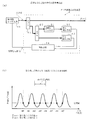
【0004】
図39(a)は、従来の1波用波長安定化装置の構成図である。図39(b)は、ch0に波長を固定する場合の説明図である。
図39(a)において、DFBレーザ710から射出されたレーザ光は、1波用波長安定化装置700内の入力光を2つに分岐するカプラ711に入射され、そのレーザ光の一部を分岐した後に残りのレーザ光は、1波用波長安定化装置700から射出される。このDFBレーザ710は、定常状態においてch0に相当する波長のレーザ光を発振する半導体レーザである。
【0005】
1波用波長安定化装置700内において、カプラ711で分岐した一部のレーザ光は、入力光を2つに分岐するカプラ712に入射されて分岐される。このカプラ712で分岐した一方のレーザ光は、ファブリペローエタロンフィルタ(Fabry-perot Etalon Filter 、以下、「ETフィルタ」と略記する。)713を介して、光強度に応じて電流を出力する第1ホトダイオード(以下、「PD」と略記する。)714に入射され、そのレーザ光の強度が検出される。この第1PD714の出力値をPDo1とする。また、カプラ712で分岐した他方のレーザ光は、光強度に応じて電流を出力する第2PD715に入射され、そのレーザ光の強度が検出される。この第2PD715の出力値をPDo2とする。
【0006】
このETフィルタ713の透過率の極大値を与える波長は、安定化させたい波長におけるPDo2で規格化したPDo1の値、すなわち、PDo1/PDo2が目標値0.5となるように設定される。
そして、制御用CPU716は、これらPDo1およびPDo2を受信し、これらの検出値に基づいてDFBレーザ710の発振波長を所定波長に固定する制御信号をDFBレーザ710に送信する。
【0007】
このような構成の1波用波長安定化装置700は、次のように動作して、ch0にDFBレーザ710の発振波長を安定化させる。
DFBレーザ710を立ち上げて、制御用CPU716は、PDo1およびPDo2を受信してPDo1/PDo2を算出する。そして、このPDo1/PDo2が目標値0.5より大きい場合には、制御用CPU716は、発振波長が長くなるようにDFBレーザ710の駆動電流または温度を調整してDFBレーザ710を制御する。一方、DFBレーザ710を立ち上げた時のPDo1/PDo2が目標値0.5より小さい場合には、制御用CPU716は、発振波長が短くなるようにDFBレーザ710を制御する。こうして常にPDo1/PDo2が0.5となるようにDFBレーザ710は、制御され、発振波長は、ch0に安定化される。
【0008】
ところで、制御用CPU716は、単にPDo1/PDo2と目標値0.5との大小を比較し発振波長を制御するだけなので、DFBレーザ710が図39(b)の点a、点b、点c、点dの波長で立ち上がった場合には、所望のch0に発振波長を安定化することができるが、DFBレーザが点e、点fの波長で立ち上がった場合には、ch0以外の波長で安定化されてしまう。
【0009】
したがって、1波用波長安定化装置は、DFBレーザの立ち上げ時の波長の範囲を考慮して固定すべき特定の1波に合わせて設計される。
ここで、レーザ立ち上げ時の波長に対し、波長安定化装置がレーザの発振波長を所望の波長に安定化することができる波長範囲を引込範囲と呼称することにする。そして、この引込範囲は、ETフィルタのFSR(Free Spectral Range )によって決定され、FSRを大きくすることによって広くすることができる。
【0010】
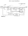
また、図39(a)においてDFBレーザ710の代わりに、単一モードで発振しかつその発振波長を連続的に可変できるチューナブルレーザを使用する場合には、複数波長の中から所定波長を発振させてその発振波長を安定化させるためのマルチ波長安定化装置が使用される。
図40(a)は、従来のマルチ波長安定化装置の構成図である。図40(b)は、従来のマルチ波長安定化装置における各引込範囲と各chとの関係図である。
【0011】
図40(a)において、マルチ波長安定化装置750の構成は、図39(a)のETフィルタ713の代わりに、FSRを安定化させたい波長間隔に合わせたETフィルタ754が使用されるだけで、その他の構成は、図39(a)と同様であるため、その説明を省略する。
このようなマルチ波長安定化装置750の引込範囲は、WDM方式に使用されるチューナブルレーザに使用される場合、図40(b)に示すように、WDM方式の波長間隔で決定されてしまう。これは、ETフィルタが周期的フィルタであるため一定の周期ごとにPDo1/PDo2が同一の値となり、そして、制御用CPU757が単にPDo1およびPDo2の値を受信しているだけなので、制御用CPUは、例えば、点gと点hの区別がつかないからである。
【0012】
また、この引込範囲は、各chの波長間隔が0.8nmの場合に使用されるマルチ波長安定化装置では、±30GHz程度である。
【0013】
【発明が解決しようとする課題】
前述したようにWDM方式用光源装置は、多重する波長の数だけ発振波長の異なる半導体レーザを備えて構成しているため、半導体レーザの破損などに備えて予備用の半導体レーザを用意しておく場合には、発振波長の異なる半導体レーザごとに予備用を用意しておかなければならないという問題がある。例えば、32波用のWDM方式光源装置では、32の各chに対応して常用に互いに発振波長の異なる32個の半導体レーザがあるため、各々の予備用として32個の半導体レーザが必要である。
【0014】
この問題は、今後トラヒックの増大にともなって多重度が増加した場合には、大きな問題となる。
一方、この問題は、1つの解決方法として複数の波長を出力することができるチューナブルレーザを予備用として使用することにより解決できるが、この場合には、適当な波長安定化装置がないという問題が新たに生じる。
【0015】
すなわち、このような光源装置は、複数の波長を出力するため、固定すべき特定の1波に合わせて設計される1波用波長安定化装置では、対応することができないという問題である。
また、複数の波長の出力に対応するため、マルチ波長安定化装置を使用する場合には、引込範囲が狭いため、この引込範囲を越えてチューナブルレーザが立ち上がった場合には、予期しない波長に固定されてしまうという問題がある。例えば、図40(b)において、ch1の波長を発振させるためにチューナブルレーザを立ち上げたところ、点hで立ち上がった場合には、ch2に固定されてしまうという問題である。
【0016】
さらに、複数の波長を出力することができるチューナブルレーザを使用する場合には、チューナブルレーザが接続された光通信システムに所定波長に固定されないうちにレーザ光を射出すると、光通信システムにおける運用中の光信号に悪影響を与えるという問題がある。
そこで、請求項1ないし請求項5に記載の発明では、引込範囲を従来のマルチ波長安定化装置に比べ広くすることができるマルチ波長安定化装置を提供することを目的とする。さらに、請求項1ないし請求項5に記載の発明では、1台で複数の所定波長に対して波長を安定化することができるマルチ波長安定化装置を提供することを目的とする。特に、請求項4に記載の発明では、発光開始時にいずれの波長で立ち上がっても、発振波長を所定波長に固定することができるマルチ波長安定化装置を提供することも目的としている。
【0017】
請求項6ないし請求項8に記載の発明では、発光開始時にいずれの波長で立ち上がっても、発振波長を所定波長に固定することができるマルチ波長安定化装置を提供することを目的とする。さらに、請求項6ないし請求項8に記載の発明では、1台で複数の所定波長に対して波長を安定化することができるマルチ波長安定化装置を提供することを目的とする。
【0018】
請求項9に記載の発明では、一定に固定した波長のレーザ光を射出することができるマルチ定波長光源を提供することを目的とする。
請求項10および請求項11に記載の発明では、所定波長にレーザ光の波長を固定した後にレーザ光を出力することができるレーザ光源装置を提供することを目的とする。特に、WDM方式用光源における予備用光源として好適なWDM方式用光源装置を提供することを目的とする。
【0019】
請求項12に記載の発明では、請求項6に記載の発明の主要部を利用することにより、光源から出力される発振波長を検出することができる波長判別装置を提供することを目的とする。
【0020】
【課題を解決するための手段】
以下、図面を用いて課題を解決するための手段を説明する。
【0021】
(請求項1)
図1(a)は、請求項1に記載の発明の原理構成図である。図1(b)は、各検出手段のch(波長)に対する出力特性である。その上段は、第1検出手段の出力特性であり、下段は、第2検出手段の出力特性である。図1(b)の縦軸は、各検出手段の出力であり、横軸は、ch(波長)である。
【0022】
図1(a)において、請求項1に記載の発明では、被制御レーザ光源20から出力されるレーザ光は、マルチ波長安定化装置1に入射される。入射したレーザ光は、マルチ波長安定化装置1内において光を分岐するカプラ21で分岐され、その分岐したレーザ光の一部は、レーザ光の波長を所定波長に安定制御するために利用され、分岐したレーザ光の残余部は、所定波長に固定された出力光としてマルチ波長安定化装置1から出力される。
【0023】
このマルチ波長安定化装置1では、前述のカプラ21で分岐したレーザ光の一部は、干渉計26に入射される。
この干渉計26において、入射したレーザ光は、光を2つに分岐する分岐手段26-1でさらに分岐される。この分岐手段26-1で分岐した各レーザ光は、互いに異なる光学的距離を持つ各光導波路を伝搬して干渉手段26-2に入射し、干渉を生じさせる。各光導波路間の光学的光路差は、各レーザ光の干渉の結果、WDM方式におけるchの波長間隔の2倍に相当する周期で干渉縞を生じる光路差とする。そして、干渉手段26-2は、干渉を起こしたレーザ光である干渉光を2つの光に分岐する。干渉手段26-2で干渉して分岐した第1干渉光は、第1ポート26-3から出力される。また、干渉手段26-2で干渉して分岐した第2干渉光は、干渉手段26-2から第1ポート26-3までの光路と干渉手段26-2から第2ポート26-4までの光路との間に、第1ポート26-3における第1干渉光の位相に対して第2ポート26-4において第2干渉光の位相を半周期遅らせる光学的光路差を設けて、第2ポート26-4から出力される。
【0024】
このように設定されるため、PDo2は、PDo1に対して半周期遅れて出力される。よって、図1(b)に示すように、PDo1の波長特性とPDo2の波長特性は、互いに逆になる。このため、PDo1/PDo2の同じ値は、WDM方式のchの波長間隔の2倍の周期で現れる。
この第1ポート26-3から射出される第1干渉光は、その強度を検出する第1検出手段27に入射する。また、第2ポート26-4から射出される第2干渉光は、その強度を検出する第2検出手段28に入射する。
【0025】
そして、制御手段29は、所定波長のchが偶数chか奇数chかを判断する。制御手段29は、第1検出手段27および第2検出手段28からの出力を受信し、第1検出手段27の出力を第2検出手段28の出力で割り、検出値を演算する。制御手段29は、偶数chであるか奇数chであるかに関する判断結果に応じて、上述した検出値と目標値との大小関係で示される所定波長と被制御レーザ光の波長との大小関係を判別し、この判別結果に基づいて、所定波長とレーザ光の波長との差を縮小させる補正を加えた制御信号を被制御レーザ光源20に出力する。この目標値は、被制御レーザ光源が所定波長で発振している場合に得られるPDo1/PDo2の値であり、予め実測または理論計算される。
【0026】
このような請求項1に記載の発明にかかるマルチ波長安定化装置1では、所定波長のchが偶数chか奇数chかを判断して、第2検出手段28の出力で割った第1検出手段27の出力の検出値が目標値となるような制御信号を被制御レーザ光源20に出力するので、この制御信号により被制御レーザ光源20の駆動電流または温度などを調整することにより、被制御レーザ光源20から出力されるレーザ光の波長を所定波長に固定することができる。すなわち、レーザ光を所定波長に対応するchに固定することができる。
【0027】
また、偶数ch同士の間では、PDo1/PDo2の同じ値は、WDM方式のchの波長間隔の2倍の周期で現れ、奇数ch同士の間でも、PDo1/PDo2の同じ値は、WDM方式のchの波長間隔の2倍の周期で現れる。したがって、各chの引込範囲は、所定波長を中心にしてchの波長間隔の2倍になる。
なお、制御手段29は、PDo1/PDo2を算出することにより、制御信号を出力したが、PDo2/PDo1を算出してもよい。
【0028】
(請求項2)
図2(a)は、請求項2に記載の発明の原理構成図である。図2(b)は、第1検出手段のch(波長)に対する出力特性である。図2(b)の縦軸は、第2検出手段の出力で規格化した第1検出手段の出力であり、横軸は、ch(波長)である。
【0029】
図2(a)において、請求項2に記載の発明では、被制御レーザ光源20から出力されるレーザ光は、マルチ波長安定化装置2に入射される。入射したレーザ光は、マルチ波長安定化装置2内において光を分岐するカプラ21で分岐され、その分岐したレーザ光の一部は、レーザ光の波長を所定波長に安定制御するために利用され、分岐したレーザ光の残余部は、所定波長に固定された出力光としてマルチ波長安定化装置2から出力される。
【0030】
このマルチ波長安定化装置2では、前述のカプラ21で分岐したレーザ光の一部は、光を分岐するカプラ22でさらに分岐される。このカプラ22で分岐した一方のレーザ光は、レーザ光の強度を周期的フィルタ31を介して検出する第1検出手段32に入射される。この周期的フィルタ31のFSRは、WDM方式におけるchの波長間隔の2倍に相当する周期に設定される。さらに、周期的フィルタのフィネスは、光透過率のいずれかの値(目標値)においてこの値を与える隣接した2つの波長の間隔がchの波長間隔になるように設定される。フィネスは、FSRと半値全幅との比である。そして、図2(b)に示すようにこの目標値を与える波長と各chに対応する波長とが一致するように、周期的フィルタの光透過率波長特性を設定する。このように設定されるため、図2(b)に示すように、いずれの偶数chも極大値から極小値までの肩に配置され、一方、いずれの奇数chも極小値から極大値までの肩に配置される。このため、偶数ch同士の間では、PDo1/PDo2の同じ値は、WDM方式のchの波長間隔の2倍の周期で現れる。奇数ch同士の間では、PDo1/PDo2の同じ値は、WDM方式のchの波長間隔の2倍の周期で現れる。
【0031】
一方、このカプラ22で分岐した他方のレーザ光は、レーザ光の強度を検出する第2検出手段33に入射する。
そして、制御手段34は、第1検出手段32および第2検出手段33からの出力を受信して、第1検出手段32の出力を第2検出手段33の出力で規格化し検出値を演算する。制御手段34は、この検出値が前述の目標値となるような制御信号を被制御レーザ光源20に出力する。
【0032】
このような請求項2に記載の発明にかかるマルチ波長安定化装置2では、所定波長のchが偶数chか奇数chかを判断して、第2検出手段33の出力で規格化された第1検出手段32の出力の検出値が目標値となるような制御信号を被制御レーザ光源20に出力するので、この制御信号により被制御レーザ光源20の駆動電流または温度などを調整することにより、被制御レーザ光源20から出力されるレーザ光の波長を所定波長に固定することができる。すなわち、レーザ光を所定波長に対応するchに固定することができる。
【0033】
また、偶数ch同士の間では、PDo1/PDo2の同じ値は、WDM方式のchの波長間隔の2倍の周期で現れ、奇数ch同士の間でも、PDo1/PDo2の同じ値は、WDM方式のchの波長間隔の2倍の周期で現れる。したがって、各chの引込範囲は、所定波長を中心にしてchの波長間隔の2倍になる。
さらに、第1検出手段32の出力を第2検出手段33の出力で規格化しているので、雑音や経時劣化などによる第1検出手段32の出力変動を補償することができる。
【0034】
なお、上述では、いずれの偶数chも極大値から極小値までの肩に配置され、一方、いずれの奇数chも極小値から極大値までの肩に配置されるようにしたが、この逆でもよい。
(請求項3)
図3は、請求項3に記載の発明の原理構成図である。
【0035】
図3において、請求項3に記載の発明では、被制御レーザ光源20から出力されるレーザ光は、マルチ波長安定化装置3に入射される。入射したレーザ光は、マルチ波長安定化装置3内において光を分岐するカプラ21で分岐され、その分岐したレーザ光の一部は、レーザ光の波長を所定波長に安定制御するために利用され、分岐したレーザ光の残余部は、所定波長に固定された出力光としてマルチ波長安定化装置3から出力される。
【0036】
このマルチ波長安定化装置3では、前述のカプラ21で分岐したレーザ光の一部は、光を分岐するカプラ22でさらに分岐される。このカプラ22で分岐した一方のレーザ光は、レーザ光の強度を周期的フィルタ36を介して検出する第1検出手段37に入射される。この周期的フィルタ36は、FSRの半分が波長分割多重方式における最初のchと最後のchとの波長間隔以上になるように設定された周期的フィルタである。そして、このカプラ22で分岐した他方のレーザ光は、レーザ光の強度を検出する第2検出手段33に入射する。
【0037】
また、各chにおける波長のレーザ光によって得られる第1検出手段37の出力および第2検出手段33の出力が予め実測または理論計算され、その結果から第2検出手段33の出力で規格化した第1検出手段37の出力の目標値を得る。そして、記憶手段39には、波長分割多重方式における各chの波長とこの目標値との関係を示すテーブルが予め用意され、その関係が蓄積される。
【0038】
そして、制御手段38は、第1検出手段37および第2検出手段33からの出力を受信して、第1検出手段37の出力を第2検出手段33の出力で規格化し検出値を演算する。制御手段38は、この検出値が記憶手段39に蓄積された前述の関係に示された所定波長における目標値となるような制御信号を被制御レーザ光源20に出力する。
【0039】
このような請求項3に記載の発明にかかるマルチ波長安定化装置3では、第2検出手段33の出力で規格化された第1検出手段37の出力の検出値が記憶手段39に蓄積された関係に示された所定波長における目標値となるような制御信号を被制御レーザ光源20に出力するので、この制御信号により被制御レーザ光源20の駆動電流または温度などを調整することにより、被制御レーザ光源20から出力されるレーザ光の波長を所定波長に固定することができる。すなわち、レーザ光を所定波長に対応するchに固定することができる。
【0040】
また、WDM方式の多重度が増減して被制御レーザ光源20の発振波長範囲が変化した場合でも、周期的フィルタ36のFSRを調整することにより対応することができる。もちろん、被制御レーザ光源20が複数波長を発振することができるチューナブルレーザの場合だけでなく、1つの波長を発振するレーザの場合にも適用可能である。この場合の引込範囲は、FSRの極大値から極小値となる。
【0041】
さらに、第2検出手段33の出力で規格化した第1検出手段37の出力の値は、周期的フィルタ36の透過率に対応する。各chの波長に対応した第2検出手段33の出力で規格化した第1検出手段37の出力の各値は、周期的フィルタ36の光透過率波長特性の曲線上の肩にchの波長間隔で並ぶ。このため、各chの引込範囲は、周期的フィルタ36の1周期分まで広げることができる。例えば、1周期が90ch分(72nm)のFSRをもつ周期的フィルタの場合には、引込範囲は、72nmである。ただし、各chに対応する引込範囲の境界は、含まれない。
【0042】
また、第1検出手段37の出力を第2検出手段33の出力で規格化しているので、雑音や経時劣化などによる第1検出手段37の出力変動を補償することができる。
(請求項4ないし請求項6)
図4は、請求項4および請求項5に記載の発明の原理構成図である。
【0043】
図5は、請求項4および請求項6に記載の発明の原理構成図である。
図4および図5において、請求項4ないし請求項6に記載の発明では、被制御レーザ光源20から出力されるレーザ光は、マルチ波長安定化装置4、5に入射される。入射したレーザ光は、マルチ波長安定化装置4、5内において光を分岐するカプラ21で分岐され、その分岐したレーザ光の一部は、レーザ光の波長を所定波長に安定制御するために利用され、分岐したレーザ光の残余部は、所定波長に固定された出力光としてマルチ波長安定化装置4、5から出力される。
【0044】
まず、請求項4に記載の発明にかかるマルチ波長安定化装置の構成について説明する。
請求項4に記載のマルチ波長安定化装置4、5では、図4および図5において、前述のカプラ21で分岐したレーザ光の一部は、光を分岐するカプラ23でさらに分岐される。このカプラ23で分岐した一方のレーザ光は、第1FSRを持つ第1周期的フィルタ41、51を介してレーザ光の強度を検出する第1検出手段43、53に入射される。そして、このカプラで分岐した他方のレーザ光は、第1FSRとは異なる第2FSRを持つ第2周期的フィルタ42、52を介してレーザ光の強度を検出する第2検出手段44、54に入射する。
【0045】
そして、制御手段46、56は、第1検出手段43、53の出力に基づいてレーザ光の波長を制御した後に、第2検出手段44、54の出力に基づいてレーザ光の波長が所定波長となるように被制御レーザ光源20へ制御信号を出力する。
次に、請求項5に記載の発明にかかるマルチ波長安定化装置の構成について説明する。
【0046】
請求項5に記載のマルチ波長安定化装置4では、図4において、請求項4に記載の発明に対して、カプラ23を光を3つに分岐するカプラ23に代え、このカプラ23で分岐した第3のレーザ光を受光してこのレーザ光の強度を検出する第3検出手段45をさらに備えて構成され、第1周期的フィルタ41、第2周期的フィルタ42および制御手段46は、次のような特徴を備える。
【0047】
この第1周期的フィルタ41は、その第1FSRがレーザ光源の発光開始時におけるレーザ光の発振波長が引き込むべき初期引込波長(以下、「λint 」と略記する。)における光透過率と同一の光透過率を与えるλint に最も近い2つの波長の間に存在するように設定される。また、第2周期的フィルタ42は、その第2FSRが第1FSRと異なる第2FSRであって波長分割多重方式におけるchの波長間隔に設定される。ここで、λint のレーザ光を受光した場合の第3検出手段の出力で規格化した第1検出手段の出力を初期目標値とする。
【0048】
そして、制御手段46は、第1検出手段43ないし第3検出手段45からの出力を受信して、第1検出手段43の出力を第3検出手段の出力45で規格化し第1検出値を演算する。制御手段46は、この第1検出値が前述の光透過率の値、すなわち、初期目標値となるように被制御レーザ光源20を制御する。その後、制御手段46は、第2検出手段44の出力を第3検出手段45の出力で規格化し第2検出値を演算する。制御手段46は、この第2検出値に基づいてレーザ光の波長が所定波長になるように被制御レーザ光源20へ制御信号を出力する。
【0049】
次に、請求項6に記載の発明の構成について説明する。
請求項6に記載のマルチ波長安定化装置5では、図5において、請求項4に記載の発明に対して、カプラ23を光を3つに分岐するカプラ23に代え、このカプラ23で分岐した第3のレーザ光を受光してこのレーザ光の強度を検出する第3検出手段45および制御手段56へ蓄積した内容を出力する記憶手段57をさらに備えて構成される。ここで、各chにおける波長のレーザ光によって得られる第1検出手段53の出力および第3検出手段45の出力が予め実測または理論計算され、その結果から第3検出手段45の出力で規格化した第1検出手段53の出力の目標値を得る。そして、制御手段56に接続した記憶手段57には、波長分割多重方式における各chの波長とこの目標値との関係を示すテーブルが予め用意され、その関係が蓄積される。
【0050】
そして、第1周期的フィルタ51、第2周期的フィルタ52および制御手段56は、次のような特徴を備える。
この第1周期的フィルタ51は、そのFSRの半分がWDM方式における最初のchと最後のchとの波長間隔以上に設定される。また、第2周期的フィルタ52は、そのFSRがWDM方式におけるchの波長間隔に設定される。
【0051】
そして、制御手段56は、第1検出手段53ないし第3検出手段45からの出力を受信して、第1検出手段53の出力を第3検出手段45の出力で規格化し第1検出値を演算する。制御手段56は、この第1検出値が記憶手段57に蓄積された前述の関係に示された所定波長における目標値となるように被制御レーザ光源20を制御する。その後、制御手段56は、第2検出手段54の出力を第3検出手段45の出力で規格化し第2検出値を演算する。制御手段56は、この第2検出値に基づいてレーザ光の波長が所定波長になるように被制御レーザ光源20へ制御信号を出力する。
【0052】
このような請求項4ないし請求項6に記載の発明にかかるマルチ波長安定化装置4、5では、第1FSRを持つ第1周期的フィルタ41、51を介して受光する第1検出手段43、53の出力に基づいて、第2周期的フィルタ42、52の所定波長に対する引込範囲まで被制御レーザ光源20の発振波長を制御する。その後、第2周期的フィルタ42、52を介して受光する第2検出手段44、54の出力に基づいて、被制御レーザ光源20の発振波長を所定波長に制御する。
【0053】
したがって、第1FSRを大きく設定することにより、立上波長に対する引込範囲(以下、「初期引込範囲」と呼称する。)を広くすることができる。
また、第1周期的フィルタ41、51の設定を各chの波長間隔によらず自由に変えることができるから、立上波長に応じて初期引込範囲を設定することができる。
【0054】
(請求項7)
図6は、請求項7に記載の発明の原理構成図である。
図6において、請求項7に記載の発明では、被制御レーザ光源20から出力されるレーザ光は、マルチ波長安定化装置6に入射される。入射したレーザ光は、マルチ波長安定化装置6内において光を分岐するカプラ21で分岐され、その分岐したレーザ光の一部は、レーザ光の波長を所定波長に安定制御するために利用され、分岐したレーザ光の残余部は、所定波長に固定された出力光としてマルチ波長安定化装置6から出力される。
【0055】
このマルチ波長安定化装置6では、前述のカプラ21で分岐したレーザ光の一部は、後述する複数個の第1周期的フィルタ61-1〜61-mおよび第2周期的フィルタ62-1〜62-nの合計数に光を分岐するカプラ24でさらに分岐される。このカプラ24で分岐した複数個のレーザ光の一部は、複数個の第1周期的フィルタ61-1〜61-mの各々に接続され、レーザ光の強度を接続する第1周期的フィルタ61-1〜61-mを介して検出する第1検出手段63-1〜63-mに入射する。そして、カプラ24で分岐した複数個のレーザ光の他部は、複数個の第2周期的フィルタ62-1〜62-nの各々に接続され、レーザ光の強度を接続する第2周期的フィルタ62-1〜62-nを介して検出する第2検出手段64-1〜64-nに入射する。
【0056】
各第1周期的フィルタ61-1〜61-mは、互いに同一のFSRであってそのFSRがWDM方式におけるchの波長間隔の整数倍に設定される。また、各第2周期的フィルタ62-1〜62-nは、互いに同一のFSRであってそのFSRが第1周期的フィルタ61-1〜61-mのFSRと異なりかつWDM方式におけるchの波長間隔の整数倍に設定される。
【0057】
このように第1周期的フィルタ61-1〜61-mと第2周期的フィルタ62-1〜62-nを設定することにより、ある波長λx のレーザ光が入射したときに、複数個の第1検出手段63-1〜63-mのうち特定の第1検出手段63-1〜63-mからのみ特定の値で出力され、残余の第1検出手段63-1〜63-mからは特定の値で出力しないようにすることができる。さらに、このある波長λx のレーザ光に対して第2検出手段64-1〜64-nにおいても、複数個の第2検出手段64-1〜64-nのうち特定の第2検出手段64-1〜64-nからのみ特定の値で出力され、残余の第2検出手段64-1〜64-nからは特定の値で出力しないようにすることができる。
【0058】
そして、制御手段65は、複数個の第1検出手段61-1〜61-mと複数個の第2検出手段62-1〜62-nとの出力を受信して、所定波長に対して出力する第1検出手段63-1〜63-mおよび第2検出手段64-1〜64-nから特定の値で出力が得られるように被制御レーザ光源20へ制御信号を出力する。
このような請求項7に記載の発明にかかるマルチ波長安定化装置6は、いずれの第1検出手段63-1〜63-mといずれの第2検出手段64-1〜64-nとから特定の値で出力を受信したかを識別することにより、被制御レーザ光源20の立ち上がり時におけるレーザ光の波長を判別することができる。この判別した波長と所定波長を比較することにより、被制御レーザ光源20の発振波長を短波長側にずらすか長波長側にずらすか判断し、被制御レーザ光源20に制御信号を出力する。そして、この制御信号により、第1検出手段63-1〜63-mおよび第2検出手段64-1〜64-n中から、所定波長に対して特定の値で出力する第1検出手段63-1〜63-mおよび第2検出手段64-1〜64-nのみから特定の値で出力を受信するようにすることによって所定波長に固定することができる。
【0059】
(請求項8)
図7は、請求項8に記載の発明の原理構成図である。
図7において、請求項8に記載の発明では、被制御レーザ光源20から射出されるレーザ光は、マルチ波長安定化装置7に入射される。入射したレーザ光は、マルチ波長安定化装置7内において光を分岐するカプラ21で分岐され、その分岐したレーザ光の一部は、レーザ光の波長を所定波長に安定制御するために利用され、分岐したレーザ光の残余部は、所定波長に固定された出力光としてマルチ波長安定化装置7から出力される。
【0060】
このマルチ波長安定化装置7では、前述のカプラ21で分岐したレーザ光の一部は、光を分岐するカプラ22でさらに分岐される。このカプラ22で分岐した一方のレーザ光は、レーザ光を受光しレーザ光の強度とこの強度における波長とを計測する光計測手段71に入射される。この光計測手段71の出力は、制御手段73に受信され、制御手段73は、光計測手段71の出力に基づいてレーザ光の波長を波長安定化装置における所定波長の引込範囲内に合わせる制御信号を被制御レーザ光源20へ出力する。
【0061】
また、カプラ22で分岐した他方のレーザ光は、波長安定化装置72に入射され、この波長安定化装置72は、制御手段73によって被制御レーザ光源20から出力されるレーザ光の波長が所定波長における引込範囲内に合わせられた後に、レーザ光を受光しこのレーザ光の強度に基づいて所定波長に固定する制御信号を被制御レーザ光源20へ出力する。
【0062】
このような請求項8に記載の発明にかかるマルチ波長安定化装置7では、まず、光計測手段71で立上波長を計測し、その計測結果に基づいて被制御レーザ光源20の発振波長を調節して、波長安定化装置における所定波長の引込範囲内に合わせる。その後、波長安定化装置で所定波長に固定する。このため、制御レーザ光源が、どのような波長で立ち上がっても、所定波長に固定することができる。
【0063】
(請求項9)
図8は、請求項9に記載の発明の原理構成図である。
図8において、請求項9に記載の発明では、所定波長のレーザ光を発光することができるレーザ光源75とレーザ光を受光しレーザ光の強度に基づいて所定波長にほぼ固定するマルチ波長安定化装置77とを備え、所定波長に固定した定波長のレーザ光を射出するマルチ定波長光源装置8において、このマルチ波長安定化装置77は、請求項1ないし請求項8のいずれか1項に記載のマルチ波長安定化装置で構成する。
【0064】
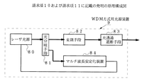
(請求項10および請求項11)
図9は、請求項10および請求項11に記載の発明の原理構成図である。
まず、請求項10に記載の発明の構成について説明する。
図9において、請求項10に記載の発明では、複数波長のレーザ光を発光するレーザ光源80から射出されるレーザ光は、レーザ光をその偏波を保持した状態で2つに分岐する光分岐手段81に入射する。
【0065】
この光分岐手段81で分岐した第1分岐光は、送出すべき信号で変調する変調手段82に入射され変調される。変調手段82から射出されたレーザ光は、光透過遮断手段83に入射する。この光透過遮断手段83は、変調手段82の出力光が所定波長である場合にはこの出力光を透過し、一方、変調手段82の出力光が所定波長でない場合にはこの出力光を遮断する。
【0066】
また、光分岐手段81で分岐した第2分岐光は、マルチ波長安定化装置84に入射する。このマルチ波長安定化装置84は、この第2分岐光を受光し第2分岐光の強度に基づいてレーザ光を所定波長にほぼ固定する。
【0067】
次に、請求項11に記載の発明の構成について説明する。
請求項11に記載の発明では、図10において、請求項10に記載のWDM方式用光源装置9において、マルチ波長安定化装置84は、請求項1ないし請求項7のいずれか1項に記載のマルチ波長安定化装置で構成する。
このような請求項10および請求項11に記載の発明にかかるWDM方式用光源装置9では、所定波長であるか否かに応じて透過・遮断する光透過遮断手段83があるので、レーザ光源を立ち上げたときに所定波長でない波長で立ち上がった場合やWDM方式におけるchを変更したときに変更後の所定波長になっていない場合などでも、所定波長に安定するまで光透過遮断手段83からレーザ光が射出されない。このため、このWDM方式用光源装置9を接続する光通信システムにおける運用中の光信号にクロストークなどの悪影響を与えることがない。
【0068】
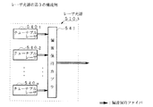
(請求項12)
図10は、請求項12に記載の発明の原理構成図である。
図10において、請求項12に記載の発明では、被検光源89から出力される光は、波長判別装置10内の光を分岐するカプラ90に入射する。このカプラ90は、後述する複数個の第1周期的フィルタ91-1〜91-mおよび第2周期的フィルタ92-1〜92-nの合計数に光を分岐するカプラ90である。カプラ90で分岐した複数個の光の一部は、複数個の第1周期的フィルタ91-1〜91-mの各々に接続され、光の強度を接続する第1周期的フィルタ91-1〜91-mを介して検出する第1検出手段93-1〜93-mに入射する。そして、カプラ24で分岐した複数個の光の他部は、複数個の第2周期的フィルタ92-1〜92-nの各々に接続され、レーザ光の強度を接続する第2周期的フィルタ92-1〜92-nを介して検出する第2検出手段94-1〜94-nに入射する。
【0069】
各第1周期的フィルタ91-1〜91-mは、互いに同一のFSRであってそのFSRが波長に対する解像度の整数倍に設定される。また、各第2周期的フィルタ92-1〜92-nは、互いに同一のFSRであってそのFSRが第1周期的フィルタ91-1〜91-nのFSRと異なりかつ波長に対する解像度の整数倍に設定される。
【0070】
このように第1周期的フィルタ91-1〜91-nと第2周期的フィルタ92-1〜92-nを設定することにより、ある波長λy の光が入射したときに、複数個の第1検出手段93-1〜93-mのうち特定の第1検出手段93-1〜93-mからのみ最大強度の出力が得られ、残余の第1検出手段93-1〜93-mからはそれより小さい出力しか得られないようにすることができ、さらに、このある波長λy の光に対して第2検出手段94-1〜94-nにおいても、複数個の第2検出手段94-1〜94-nのうち特定の第2検出手段94-1〜94-nからのみ最大強度の出力が得られ、残余の第2検出手段94-1〜94-nからはそれよりも小さい出力しか得られないようにすることができる。
【0071】
そして、判定手段95は、複数個の第1検出手段93-1〜93-mと複数個の第2検出手段94-1〜94-nとの出力を受信して、いずれの第1検出手段93-1〜93-mおよびいずれの第2検出手段94-1〜94-nから最大出力が得られたかを識別する。この識別結果に応じて被検光源89の波長を判定し、この判定結果を示す信号を出力する。
【0072】
このような請求項12に記載の発明にかかる波長判別装置10では、いずれの第1検出手段93-1〜93-mといずれの第2検出手段94-1〜94-nとから最大出力を受信したかを識別することにより、被検光源89の光の波長を判定することができる。
なお、請求項1ないし請求項11に記載の発明において、被制御レーザ光源は、所定波長のレーザ光を発光することができる光源であれば、1波長のみを発光させることを目的としたレーザ光源でも、複数の波長を発光させることを目的としたチューナブルレーザ光源でもよい。
【0073】
【発明の実施の形態】
以下、図面に基づいて本発明における実施の形態を説明する。
なお、第1の実施形態ないし第6の実施形態では、8波のWDM方式の場合について説明し、第7の実施形態および第8の実施形態では、32波のWDM方式の場合について説明するが、いずれの場合もこれらの多重度に限られない。
【0074】
(第1の実施形態の構成)
第1の実施形態は、請求項1および請求項9に記載の発明に対応するマルチ定波長光源装置の実施形態である。
図11は、第1の実施形態のマルチ定波長光源装置の構成図である。図12は、各PDの出力波長特性を示す図である。図12上段の曲線は、第1PDの出力波長特性であり、下段の曲線は、第2PDの出力波長特性である。また、図12の縦軸は、各PDの出力であり、横軸は、ch(波長)である。図13は、第1の実施形態における制御用CPUの制御フローチャートである。
【0075】
図11において、チューナブルレーザ110から射出されたレーザ光は、マルチ波長安定化装置101内の光を2つに分岐するカプラ111に入射され、そのレーザ光の一部を分岐した後に残りのレーザ光は、マルチ波長安定化装置101から射出され、さらに、マルチ定波長光源装置100から出力光として射出される。このチューナブルレーザ110は、駆動電流(注入電流)を増減することにより複数波長のレーザ光を発光することができる可変波長DBRレーザである。この可変波長DBRレーザは、本実施形態においては、互いに波長の異なる8波の単一モードレーザ光を出力することができる。
【0076】
このマルチ波長安定化装置101は、前述のカプラ111で分岐したレーザ光の一部は、マッハツェンダー干渉計(以下、「MZ干渉計」と略記する。)120に入射される。
このMZ干渉計120において、入射したレーザ光は、光を2つに分岐する分岐部120-1でさらに分岐される。この分岐部120-1で分岐した第1レーザ光は、第1光導波路を伝搬して干渉部120-2に入射する。分岐部120-1で分岐した第2レーザ光は、第2光導波路を伝搬して干渉手段120-2に入射する。
【0077】
ここで、第2光導波路は、第1光導波路に対して、各レーザ光の干渉の結果、WDM方式におけるchの波長間隔の2倍である1.6nm(200GHz)周期で干渉縞を生じる光学的な光路差を設ける。そして、干渉部120-2は、第1光導波路および第2光導波路を伝搬した各レーザを合成して干渉光を生じさせ、この干渉光を2つのレーザ光に分岐する。干渉部120-2で干渉して分岐した第1干渉光は、第1ポート120-3から出力される。また、干渉部120-2で干渉して分岐した第2干渉光は、干渉部120-2から第1ポート120-3までの光路と干渉部120-2から第2ポート120-4までの光路との間に、第1ポート120-3における第1干渉光の位相に対して第2ポート120-4において第2干渉光の位相を半周期(0.8nm)遅らせる光学的な光路差を設けて、第2ポート120-4から出力される。
【0078】
このように設定されるため、PDo2は、PDo1に対して半周期遅れて出力される。よって、図12に示すように、PDo1の波長特性とPDo2の波長特性は、互いに逆になる。ここで、後述する第1PD121および第2PD122の出力をそれぞれPDo1、PDo2とした。
また、チューナブルレーザを所定波長に固定する制御を行うために使用される目標値X1 は、PDo2の肩に配置され、PDo2の極大値から極小値の肩に配置された目標値X1 をch0の波長に対応させる。なお、目標値X1 は、PDo1の肩に配置してもよい。
【0079】
ここで、肩とは、ある間隔で極値を持つグラフにおいて極値を除いた曲線部分をいい、本明細書において肩は、同様の意味に使用される。
このように配置すると、所定波長における目標値X1 と同じ値を取る波長であって隣接する所定波長より短い波長から、所定波長における目標値X1 と同じ値を取る波長であって隣接する所定波長より長い波長までの間隔、すなわち、引込範囲は、第1光導波路と第2光導波路の光学的な光路差である1.6nmとなる。
【0080】
また、このように配置すると、所定波長が偶数chである場合には、所定波長に対応するchの引込範囲内において所定波長より小さい波長では、PDo1/PDo2は、目標値X1 より小さい値となり、所定波長に対応するchの引込範囲内において所定波長より長い波長では、PDo1/PDo2は、目標値X1 より大きい値となる。一方、所定波長が奇数chである場合には、所定波長に対応するchの引込範囲内において所定波長より小さい波長では、PDo1/PDo2は、目標値X1 より大きい値となり、所定波長に対応するchの引込範囲内において所定波長より長い波長では、PDo1/PDo2は、目標値X1 より小さい値となる。
【0081】
なお、ch0に対応する目標値X1 をPDo2の極小値から極大値の肩に配置すると、上記の波長の大小と目標値X1 の大小との関係は、逆となる。
図11に戻って、この第1ポート120-3から射出される第1干渉光は、その強度を検出する第1PD121に入射する。また、第2ポート120-4から射出される第2干渉光は、その強度を検出する第2PD122に入射する。
【0082】
そして、制御用CPU140は、第1PD121から増幅器131およびアナログ/ディジタルコンバータ(以下、「A/D」と略記する。)132を介して、PDo1を受信する。また、制御用CPU140は、第2PD122から増幅器135およびA/D132を介して、PDo2を受信する。増幅器131、135は、入力信号を所定の倍率で定数倍して出力するオペアンプであり、A/D132、136は、アナログ入力を所定のビット、例えば、12ビットのディジタル信号に変換して出力する。制御用CPU140は、後述する処理を行い、チューナブルレーザ110の発振波長を所定波長に固定する制御信号をディジタル入力をアナログ信号に変換するディジタル/アナログコンバータ(以下、「D/A」と略記する。)149を介して、チューナブルレーザ110に出力する。
【0083】
チューナブルレーザ110は、この制御信号によって駆動電流を調節され、所定波長に固定される。
(本発明と第1の実施形態との対応関係)
請求項1に記載の発明と第1の実施形態との対応関係については、干渉計はMZ干渉計120に対応し、第1検出手段は第1PD121に対応し、第2検出手段は第2PD122に対応し、制御手段は制御用CPU140に対応する。
【0084】
また、請求項9に記載の発明と第1の実施形態との対応関係については、レーザ光源はチューナブルレーザ110に対応し、マルチ波長安定化装置はマルチ波長安定化装置101に対応する。
(第1の実施形態の作用効果)
このようなマルチ定波長光源装置100およびマルチ波長安定化装置101の動作について図12、図13を参照しながら、以下に説明する。
【0085】
図11に不図示のWDM方式光通信システムを統括するシステム制御装置によって、マルチ定波長光源装置100の電源が投入される。このマルチ定波長光源装置100の電源投入によって制御用CPU140内に格納されたプログラムがスタートし、マルチ定波長光源装置100内の回路を初期化する(S1)。
制御用CPU140は、チューナブルレーザ110に対するchの立ち上げ要求があったか否かを判断する(S2)。要求がない場合には、要求があるまで、S2の処理を繰り返す。
【0086】
要求があった場合、例えば、ch3を立ち上げる要求があった場合には、制御用CPU140は、チューナブルレーザ110の温度およびch3に対応する駆動電流を設定し、チューナブルレーザ110に制御信号を送信する(S3)。
この制御信号によってチューナブルレーザ110は、立上波長でレーザ光の発振を開始する。
【0087】
制御用CPU140は、チューナブルレーザ110のレーザ発振が安定するのを待つため、W1 秒間、S5以下の処理を停止する(S4)。
第1PD121および第2PD122は、チューナブルレーザ110からのレーザ光をMZ干渉計120を介して受光し、受光量に応じた電流を制御用CPU140に出力する。制御用CPU140は、この電流値を計測し、PDo1/PDo2(検出値)を算出する。
【0088】
制御用CPU140は、目標値X1 からPDo1/PDo2を引くことによってPDo1/PDo2と引込点における目標値X1 との差を算出し、この算出値が許容値以内か否かを判断する(S6)。PDo1/PDo2と引込点における目標値X2 との差を算出することは、チューナブルレーザ110の現在の発振波長と所定波長との差を算出することに相当する。
【0089】
判断の結果、許容値以内である場合は、後述するS11の処理を行う。
一方、判断の結果、算出値(波長差)が許容値以内でない場合には、前述のシステム制御装置によって指定されたchが偶数chか奇数chかを判断する(S7)。これは、算出値の符号が同じでも偶数chか奇数chかによって制御信号の増減が異なるからである。
【0090】
判断の結果、奇数chである場合は、奇数chの場合の算出値(波長差)に応じた制御信号を出力する(S8)。この奇数chの場合の制御信号は、前述したように算出値がマイナスの場合には、現在の発振波長が所定波長より長い場合であるから、発振波長を短くすべく駆動電流を増加させる信号となる。また、算出値がプラスの場合には、現在の発振波長が所定波長より短い場合であるから、発振波長を長くすべく駆動電流を減少させる信号となる。今、所望のchは、ch3であるから、このS8の処理を行う。
【0091】
一方、判断の結果、偶数chである場合は、偶数chの場合の算出値(波長差)に応じた制御信号を出力する(S9)。この偶数chの場合の制御信号は、算出値の符号と駆動電流の増減との関係において奇数chの場合と逆になる。これは、偶数chの場合には、極大値から極小値の肩に偶数chの引込点が配置されるからである。
【0092】
制御用CPU140は、チューナブルレーザ110のレーザ発振が安定するのを待つため、W2 秒間、次のS11以下の処理を停止し(S10)、W2 秒後にS11の処理を行う(S10)。
制御用CPU140は、前述のシステム制御装置からこのマルチ定波長光源装置100の運用を終了する信号を受信したか否かを判断する(S11)。運用終了の信号を受信した場合には、電源を遮断して、処理を終了する(S12)。
【0093】
一方、運用終了の信号を受信しない場合には、制御用CPU140は、処理をS5に戻し、算出値が許容値以内となるまで、S5からS11までの処理を繰り返す。これらの処理を繰り返すことによって、立上波長からch3の所定波長へチューナブルレーザ110の発振波長が調整され、ch3に発振波長が固定される。また、これらの処理を繰り返すことによって雑音などによって発振波長にずれが生じてもこのずれが補償され、発振波長が固定される。
【0094】
第1の実施形態にかかるマルチ定波長光源装置100(マルチ波長安定化装置101)は、所定波長に対応するchが偶数chか奇数chかを判断しているので、各chの引込範囲は、WDM方式のchの波長間隔の2倍にすることができる。よって、各chの引込範囲は、従来に比べて広くすることができる。
また、上述の実施形態においては、制御用CPU140によって第1PD121および第2PD122の出力を処理して、チューナブルレーザ110に制御信号を送信したが、演算回路によって処理してもよい。
【0095】
図14は、制御用CPUに相当する演算回路の構成例を示す図である。
図14において、第1PD121の出力は、増幅器141を介して割算回路143に入力する。第2PD122の出力は、増幅器142を介して割算回路143に入力する。
【0096】
割算回路143は、PDo1/PDo2を計算する回路である。この割算回路143の出力は、入力信号を基準電圧Vref と比較してその差に比例する信号を出力する比較器144に入力する。Vref は、目標値X1 に相当する電圧にする。比較器144の出力は、WDM方式光通信システムを統括するシステム制御装置からの制御信号により制御されるスイッチ145に入力する。このスイッチ145は、システム制御装置からの信号に従って偶数chの場合には、図14に示す端子Tm1に接続し、奇数chの場合には、端子Tm2に接続を切り替える。
【0097】
スイッチ145の端子Tm1は、そのまま増幅器147を介してチューナブルレーザ110に接続される。一方、スイッチ145の端子Tm2は、入力信号を反転出力するインバータ146および増幅器147を介してチューナブルレーザ110に接続される。
このように構成することにより、比較器144において目標値X1 とPDo1/PDo2とが比較され、スイッチ145において所定波長のchの偶奇数に従って制御信号の増減方向が調整されるので、上述の制御用CPUの制御フローチャートと同様の作用をすることができる。
【0098】
なお、第1の実施形態においては、MZ干渉計を使用したがこれに限定されるものではない。図12に示す出力波長特性を実現できる干渉計であればマイケルソンの干渉計なども使用することができる。
次に、別の実施形態について説明する。
(第2の実施形態の構成)
第2の実施形態は、請求項2および請求項9に記載の発明に対応するマルチ定波長光源装置の実施形態である。
【0099】
図15は、第2の実施形態のマルチ定波長光源装置の構成図である。図16は、極大値から極小値の間における肩に偶数chの目標値を配置した場合の図である。図17は、極小値から極大値の間における肩に偶数chの目標値を配置した場合の図である。図18は、図16に対し、フィネスを大きくした場合を示す図である。図16ないし図18の縦軸は、後述するPDo1/PDo2(光透過率)であり、横軸は、ch(波長)である。また、曲線は、PDo2で規格化したPDo1の出力波長特性である。
【0100】
図15において、8波の可変波長DBRレーザであるチューナブルレーザ110から射出されたレーザ光は、マルチ波長安定化装置151内の光を2つに分岐するカプラ111に入射され、そのレーザ光の一部を分岐した後に残りのレーザ光は、マルチ波長安定化装置151から射出され、さらに、マルチ定波長光源装置150から出力光として射出される。
【0101】
このマルチ波長安定化装置151では、前述のカプラ111で分岐したレーザ光の一部は、光を2つに分岐するカプラ160でさらに分岐される。このカプラ160で分岐した一方のレーザ光は、ETフィルタ161を介して第1PD162に入射され、そのレーザ光の強度が検出される。この第1PD162の出力値をPDo1とする。また、カプラ160で分岐した他方のレーザ光は、第2PD165に入射され、そのレーザ光の強度が検出される。この第2PD165の出力値をPDo2とする。これら第1PD162および第2PD165は、光強度に応じて電流を出力する。
【0102】
ETフィルタ161のFSRは、chの波長間隔0.8nm(100GHzグリッド間隔)のWDM方式の場合には、その共振間隔を調整することにより、1.6nmに設定される。また、そのフィネスは、図16に示すように、各chに対応する各波長における光透過率(PDo1/PDo2)が同一の値X2 (目標値)となるように設定される。このように設定されるため、いずれの偶数chも極大値から極小値までの肩に配置され、一方、いずれの奇数chも極小値から極大値までの肩に配置される。
【0103】
このように配置すると、所定波長における目標値X2 と同じ値を取る波長であって隣接する所定波長より短い波長から、所定波長における目標値X2 と同じ値を取る波長であって隣接する所定波長より長い波長までの間隔、すなわち、引込範囲は、FSRの値からchの波長間隔の2倍である1.6nmとなる。
また、このように配置すると、所定波長が偶数chである場合には、所定波長に対応するchの引込範囲内において所定波長より短い波長では、PDo1/PDo2は、目標値X2 より大きい値となり、所定波長に対応するchの引込範囲内において所定波長より長い波長では、PDo1/PDo2は、目標値X1 より小さい値となる。一方、所定波長が奇数chである場合には、所定波長に対応するchの引込範囲内において所定波長より短い波長では、PDo1/PDo2は、目標値X1 より小さい値となり、所定波長に対応するchの引込範囲内において所定波長より長い波長では、PDo1/PDo2は、目標値X1 より大きい値となる。
【0104】
このため、偶数ch同士の間では、X2 は、WDM方式のchの波長間隔の2倍の周期で現れる。奇数ch同士の間では、X2 は、WDM方式のchの波長間隔の2倍の周期で現れる。したがって、各chの引込範囲は、chの波長間隔の2倍となり、chに対応する波長を中心として±0.8nm(±100GHz)になる。
【0105】
なお、図17に示すように、偶数chを極小値から極大値までの肩に配置し、一方、奇数chを極大値から極小値までの肩に配置してもよい。この場合には、上記の波長の大小と目標値X2 の大小との関係は、逆となる。
そして、ETフィルタ161のFSRは、chの波長間隔の2倍に設定しなければならないため、1.6nmで一定である。このためフィネスを大きくすると半値全幅が小さくなり、その結果、図18に示すように目標値X3 も小さくしなければならなくなる。あまり小さな値を目標値とすると比較されるPDo1/PDo2のSNR(Signal Noise Ratio)も劣化するため、所定波長に固定する精度が低下する。このため、フィネスの上限値が存在する。
【0106】
本実施形態では、ETフィルタ161の特性から半値全幅が0.7から1.1nmであり、FSRが200GHzであるため、フィネスは、1.4から2.3までしか変化させることができない。
また、本実施形態では、WDM方式光通信システムの通信品質の要求から、フィネスは、2.0に設定され、これに対応して目標値X2 が設定される。なお、chの波長間隔を0.8nmから0.4nmに変えてもFSRおよび半値全幅ともに2倍となるため、フィネスは同じ値となる。
【0107】
制御用CPU180は、第1PD162の出力PDo1を増幅器171とA/D172を介して受信する。さらに、第2PD165の出力PDo2を増幅器175とA/D176を介して受信する。制御用CPU180は、後述する処理を行い、チューナブルレーザ110の発振波長を所定波長に固定する制御信号をD/A149を介してチューナブルレーザ110に出力する。チューナブルレーザ110は、この制御信号によって駆動電流を調節され、所定波長に固定される。
【0108】
(本発明と第2の実施形態との対応関係)
請求項2に記載の発明と第2の実施形態との対応関係については、周期的フィルタはETフィルタ161に対応し、第1検出手段は第1PD162に対応し、第2検出手段は第2PD165に対応し、制御手段は制御用CPU180に対応する。
【0109】
また、請求項9に記載の発明と第3の実施形態との対応関係については、レーザ光源はチューナブルレーザ110に対応し、マルチ波長安定化装置はマルチ波長安定化装置151に対応する。
(第2の実施形態の作用効果)
このようなマルチ定波長光源装置150およびマルチ波長安定化装置151の動作は、第1の実施形態と第2の実施形態の間において、主に、第1PD121を第1PD162に、第2PD122を第2PD165に、制御用CPU140を制御用CPU180に対応させることにより、第1の実施形態と同様に説明できるので、その説明を省略する。
【0110】
第2の実施形態にかかるマルチ定波長光源装置150(マルチ波長安定化装置151)は、偶数ch同士の間では、PDo1/PDo2の同じ値は、WDM方式のchの波長間隔の2倍の周期で現れ、奇数ch同士の間でも、PDo1/PDo2の同じ値は、WDM方式のchの波長間隔の2倍の周期で現れるので、各chの引込範囲は、従来に比べて広く所定波長を中心にしてchの波長間隔の2倍になる。
【0111】
次に、別の実施形態について説明する。
(第3の実施形態の構成)
第3の実施形態は、請求項3および請求項9に記載の発明に対応するマルチ定波長光源装置の実施形態である。
図19は、第3の実施形態のマルチ定波長光源装置の構成図である。図20は、極小値から極大値の間における肩に各chの目標値を配置した場合を示す図である。図20の縦軸は、後述するPDo1/PDo2(光透過率)であり、横軸は、ch(波長)である。また、曲線は、PDo2で規格化したPDo1の波長特性である。図21は、各chに対応する波長と目標値との関係を示す図である。
【0112】
図19において、8波の可変波長DBRレーザであるチューナブルレーザ110から射出されたレーザ光は、マルチ波長安定化装置202内の光を2つに分岐するカプラ111に入射され、そのレーザ光の一部を分岐した後に残りのレーザ光は、マルチ波長安定化装置202から射出され、さらに、マルチ定波長光源装置201から出力光として射出される。
【0113】
このマルチ波長安定化装置202では、前述のカプラ111で分岐したレーザ光の一部は、光を2つに分岐するカプラ160でさらに分岐される。このカプラ160で分岐した一方のレーザ光は、ETフィルタ210を介して第1PD212に入射され、そのレーザ光の強度が検出される。この第1PD212の出力値をPDo1とする。また、カプラ160で分岐した他方のレーザ光は、第2PD165に入射され、そのレーザ光の強度が検出される。この第2PD165の出力値をPDo2とする。これら第1PD212および第2PD165は、光強度に応じて電流を出力をする。
【0114】
ETフィルタ210は、chの波長間隔0.8nm(100GHzグリッド間隔)の8波のWDM方式の場合には、その共振間隔を調整することによりFSRの半分が5.6nm以上、例えば、6.4nmに設定される。ここで、各chをITU−T準拠にする場合には、ITU−Tに準拠した各chがFSRの肩に収まるように、ETフィルタ210の共振器を構成する反射面の反射率、共振間隔を調整する。
【0115】
そして、各chは、図20に示すように極小値から極大値の間における肩に配置される。ch0は、PDo1/PDo2の極小値を与える波長に近いところに配置される。極小値を与える波長に配置しないのは、PDの雑音などにより極小値のSNRが悪いためである。ch1からch7は、このch0を配置した波長からchの波長間隔である0.8nmおきに配置される。
【0116】
このように配置されるため、例えば、極小値から極大値の間にあるch4の波長に対するPDo1/PDo2の値は、1周期の間に1つしかないから、ch4の引込範囲は、ETフィルタ210の1周期分まで広げることができる。図20に、一例としてch4の引込範囲を示す。同様に、各chの引込範囲は、ETフィルタ210の1周期分である。
【0117】
また、各chにおける波長のレーザ光によって得られる第1PD212および第2PD165の出力を予め実測し、その結果からPDo1/PDo2の目標値を得る。メモリ231には、図21に示すch0(λ0 )ないしch7(λ7 )の波長とこの波長における目標値との関係を示すテーブルが予め用意され、その関係が蓄積される。
【0118】
そして、制御用CPU230は、第1PD212から増幅器221およびA/D222を介してPDo1を受信し、第2PD165から増幅器175およびA/D176を介してPDo2を受信する。そして、後述する処理を行い、チューナブルレーザ110の発振波長を所定波長に固定する制御信号をD/A149を介してチューナブルレーザ110に出力する。チューナブルレーザ110は、この制御信号によって駆動電流を調節され、所定波長に固定される。
【0119】
(本発明と第3の実施形態との対応関係)
請求項3に記載の発明と第3の実施形態との対応関係については、周期的フィルタはETフィルタ210に対応し、第1検出手段は第1PD212に対応し、第2検出手段は第2PD165に対応し、制御手段は制御用CPU230に対応し、記憶手段はメモリ231に対応する。
【0120】
また、請求項9に記載の発明と第3の実施形態との対応関係については、レーザ光源はチューナブルレーザ110に対応し、マルチ波長安定化装置はマルチ波長安定化装置202に対応する。
(第3の実施形態の作用効果)
このようなマルチ定波長光源装置201およびマルチ波長安定化装置202の動作について以下に説明する。
【0121】
マルチ定波長光源装置201の操作者は、不図示の手段によって所定波長、例えば、ch4にセットする。このセットによって制御用CPU230は、チューナブルレーザ110にch4の波長λ4 のレーザ光を発生させる駆動電流を流すべく制御信号を出力する。チューナブルレーザ110は、この制御信号により、例えば、図20に示すch4の波長より短い波長で立ち上がり、レーザ光を射出する。このレーザ光は、直接第2PD165とETフィルタ210を介した第1PD212とに受光され、その強度が検出される。
【0122】
制御用CPU230は、この立上波長をPDo1およびPDo2から算出したPDo1/PDo2(検出値)によって認識する。制御用CPU230は、メモリ231に蓄積されているテーブルからch4に割り当てられた波長λ4 における目標値Tg14を読み込む。
そして、制御用CPU230は、この検出値と目標値Tg14との差に応じた制御信号をチューナブルレーザ110に出力し、チューナブルレーザ110の駆動電流を調整することによって、発振波長をλ4 に固定する。
【0123】
ここで、各chを配置した肩は、極小値から極大値までの右上がりの曲線であるから、検出値が目標値Tg14より小さい値であるときは、立上波長がλ4 より短い場合である。また、検出値が目標値Tg14より大きい値であるときは、立上波長がλ4 より長い場合である。
したがって、制御用CPU230は、検出値が目標値Tg14より小さい値であるときは、立上波長を長くすべく駆動電流を増加する制御信号を発生する。一方、検出値が目標値Tg14より大きい値であるときは、立上波長を短くすべく駆動電流を減少する制御信号を発生する。
【0124】
このようなフィードバック制御は、発振波長がλ4 に固定されるまで繰り返され、また、チューナブルレーザ110の温度変動やゆらぎなどによって発振波長が微小変化した場合にも行われる。
第3の実施形態にかかるマルチ定波長光源装置201(マルチ波長安定化装置202)は、以上のように動作するので、引込範囲をETフィルタ210の1周期分まで広くすることができる。
【0125】
また、このようにレーザ光をETフィルタ210を介して受光して得られるPDo1をそのまま制御に使用しないで、レーザ光を直接受光して得られるPDo2を参照値として利用しているので、雑音や経時劣化などによるPDo1の変動を補償することができる。
なお、第3の実施形態においては、図20の場合を示したが、図22に示すように、各chの目標値を極大値から極小値の間における肩に配置してもよい。
【0126】
また、第3の実施形態においては、駆動電流を増減することによって発振波長を調整したが、温度可変型のチューナブルレーザでは、その温度を変えることによっても発振波長を調整することができる。この場合には、ペルチェ素子などの温度を制御できる媒体にチューナブルレーザを接触させる。
そして、制御用CPUは、立上波長がλ4 より短い場合には、温度を高くする制御信号を発生し、一方、立上波長がλ4 より長い場合には、温度を低くする制御信号を発生する。
【0127】
次に、別の実施形態について説明する。
(第4の実施形態の構成)
第4の実施形態は、請求項4、請求項5および請求項9に記載の発明に対応するマルチ定波長光源装置の実施形態である。
図23は、第4の実施形態のマルチ定波長光源装置250の構成図である。図24は、所定波長に固定する動作を説明するための図である。図24の縦軸は、上段の場合は、後述するPDo1/PDo3(光透過率)であり、下段の場合は、後述するPDo2/PDo3(光透過率)である。それらの横軸は、ch(波長)である。また、図24上段の曲線は、PDo3で規格化したPDo1の波長特性であり、図24下段の曲線は、PDo3で規格化したPDo2の波長特性である。
【0128】
図23において、8波の可変波長DBRレーザであるチューナブルレーザ110から射出されたレーザ光は、マルチ波長安定化装置251内の光を2つに分岐するカプラ111に入射され、そのレーザ光の一部を分岐した後に残りのレーザ光は、マルチ波長安定化装置251から射出され、さらに、マルチ定波長光源装置250から出力光として射出される。
【0129】
このマルチ波長安定化装置251では、前述のカプラ111で分岐したレーザ光の一部は、光を3つ分岐するカプラ260でさらに分岐される。このカプラ260で分岐した第1のレーザ光は、第1ETフィルタ261を介して第1PD262に入射され、そのレーザ光の強度が検出される。カプラ260で分岐した第2のレーザ光は、第2ETフィルタ263を介して第2PD264に入射され、そのレーザ光の強度が検出される。そして、カプラ260で分岐した第3のレーザ光は、第3PD265に入射され、そのレーザ光の強度が検出される。これら第1PD262ないし第3PD265は、光強度に応じて電流を出力する。また、これら第1PD262、第2PD264、第3PD265の出力値をそれぞれPDo1、PDo2、PDo3とする。
【0130】
第1ETフィルタ261は、チューナブルレーザ110を発光開始させた時の立上波長から初期引込波長λint にほぼ固定するための周期的フィルタである。このλint は、第2ETフィルタ263のいずれかのchにおける引込範囲内に設定される。例えば、ch2の波長にλint を設定する場合には、図24に示すようにch2の引込範囲内に合わせる。そして、この第1ETフィルタ261のFSRは、λint におけるPDo1/PDo3(光透過率)と同一の値を与えるλint に最も近い2つの波長(図24における点j、点k)の間に、常に一定の立上用駆動電流をチューナブルレーザ110に流した場合に、チューナブルレーザ110を発光開始させた時の立上波長が含まれるように設定される。例えば、チューナブルレーザ110を発光開始時の立上波長が、λ2 を中心として±1.2nmの範囲で立ち上がる場合には、FSRを2.4nm(300GHz)に設定する。
【0131】
第2ETフィルタ263は、λint から所定波長に固定するための周期的フィルタである。第2ETフィルタ263のFSRは、WDM方式における各chに対して引込範囲を同一にし、また、すべてのchを固定することができるようにするため、WDM方式におけるchの波長間隔に設定される。例えば、ITU−Tに準拠して各chの波長間隔を0.8nmとした場合には、そのFSRは、0.8nmに設定される。
【0132】
そして、制御用CPU280は、第1PD262ないし第3PD265からの出力PDo1、PDo2、PDo3をそれぞれ増幅器271、273、275およびA/D272、274、276を介して受信する。そして、後述する処理を行い、チューナブルレーザ110の発振波長を固定する制御信号をD/A149を介して出力する。チューナブルレーザ110は、この制御信号によって駆動電流を調節され、所定波長に固定される。
【0133】
(本発明と第4の実施形態との対応関係)
請求項4または請求項5に記載の発明と第4の実施形態との対応関係については、第1周期的フィルタは第1ETフィルタ261に対応し、第2周期的フィルタは第2ETフィルタ263に対応する。第1検出手段は第1PD262に対応し、第2検出手段は第2PD264に対応し、第3検出手段は第3PD265に対応し、制御手段は制御用CPU280に対応する。
【0134】
また、請求項9に記載の発明と第4の実施形態との対応関係については、レーザ光源はチューナブルレーザ110に対応し、マルチ波長安定化装置はマルチ波長安定化装置251に対応する。
(第4の実施形態の作用効果)
このようなマルチ定波長光源装置250およびマルチ波長安定化装置251の動作について以下に説明する。
【0135】
マルチ定波長光源装置250の操作者は、不図示の手段によってチューナブルレーザ110を起動し、所定波長、例えば、ch4にセットする。このチューナブルレーザ110の起動によって制御用CPU280は、チューナブルレーザ110に立ち上げ用の駆動電流を流すべく制御信号を出力する。チューナブルレーザ110は、この制御信号により、例えば、図24に示すch1とch2との間の波長で立ち上がり、レーザ光を射出する。このレーザ光は、第1PD262ないし第3PD265に受光され、その強度がそれぞれ検出される。
【0136】
制御用CPU280は、この立上波長をPDo1およびPDo3から算出したPDo1/PDo3(第1検出値)によって認識する。制御用CPU280は、この検出値をλint における初期目標値X4 と比較する。そして、制御用CPU280は、この第1検出値と初期目標値X4 との差に応じた制御信号をチューナブルレーザ110に出力し、チューナブルレーザ110の駆動電流を調整することによって、発振波長をλint に固定する。
【0137】
ここで、図24に示すようにλint を極大値から極小値までの右下がりの曲線の間に配置したときは、第1検出値が初期目標値X4 より大きい値である場合には、立上波長がλint より短い場合である。また、第1検出値が初期目標値X4 より小さい値であるときは、立上波長がλint より長い場合である。したがって、制御用CPU280は、第1検出値が初期目標値X4 より大きい値であるときは、立上波長を長くすべく駆動電流を減少する制御信号を発生する。一方、第1検出値が初期目標値X4 より小さい値であるときは、立上波長を短くすべく駆動電流を増加する制御信号を発生する。
【0138】
なお、λint を極小値から極大値までの右上がりの曲線の間に配置したときは、上述の初期目標値に対する第1検出値の大小とλint に対する立上波長の長短の関係は、逆となる。
このような動作により、チューナブルレーザ110の波長は、λint 、すなわち、図24下段においてch2の波長λ2 にほぼ固定される。そして、制御用CPU280は、発振波長をλ2 からλ4 に固定する処理を行う。
【0139】
この処理において、制御用CPU280は、第2PDおよび第3PDより受信したPDo2およびPDo3からPDo2/PDo3(第2検出値)の値を算出する。そして、制御用CPU280は、第2検出値の極大値の数を数えることにより所定波長における引込範囲までチューナブルレーザ110の発振波長を制御する。ch4の場合には、λ2 からλ4 までの間には、図24下段に示すように極大値が2つあるので、λ4 の引込範囲は、第2検出値の極大値を2つ数えた後である。
【0140】
その後、制御用CPU280は、この第2検出値と目標値Y1 との差に応じた制御信号をチューナブルレーザ110に出力し、チューナブルレーザ110の駆動電流を調整することによって、発振波長をλ4 に固定する。この第2検出値と目標値Y1 との差に応じた制御信号は、前述の第1検出値と初期目標値X4 との差に応じた制御信号と同様に得られるので、その説明を省略する。
【0141】
そして、このような第2検出値と目標値Y1 との差に基づくフィードバック制御は、発振波長がλ4 に固定されるまで繰り返され、また、チューナブルレーザ110の温度変動やゆらぎなどによって発振波長が微小変化した場合にも行われる。
第4の実施形態にかかるマルチ定波長光源装置250(マルチ波長安定化装置251)は、立上波長を初期引込波長λint にほぼ固定する制御段階と、所望chの所定波長に固定する制御段階との2段階でチューナブルレーザ110の発振波長を制御するので、FSRを個別に設定することにより各段階における引込範囲を独立して設定することができる。したがって、初期引込範囲を自由に設定できるので、従来のように特定のレーザ光源に対して波長安定化装置を特別に設計する必要がなく、任意のレーザ光源に対して適用することができる。また、初期引込波長から任意の波長まで発振波長を変えることができるので、1波を出力するレーザ光源だけでなく、複数波長を出力するレーザ光源に対しても適用することができる。
【0142】
なお、第4の実施形態においては、立ち上げ用の駆動電流を常に一定にしていたが、一般に、半導体レーザは、経年劣化により同じ値の電流を流しても立ち上がり時の波長がずれていくことが知られている。このため、経年劣化による立ち上がり時の波長のズレをメモリなどの記憶手段にデータとして持っておくことにより、運用期間に対応させて立ち上げ用の駆動電流を変化させ、このズレを補償するようにしてもよい。このようにすることにより長期間運用しても初期引込範囲を逸脱することがない。
【0143】
また、第4の実施形態においては、図24上段のように初期引込波長を肩に配置したが、図25上段のように初期引込波長を極大値に配置しても所望の固定波長に制御することができる。この場合には、初期引込範囲は、初期引込波長の極大値に隣接する2つの極大値を与える波長間ではなく、初期引込波長の極大値に隣接する2つの極小値を与える波長間になる。なぜなら、初期引込波長の極大値からもう一つの極大値までの間に同一の値を取る波長が2箇所存在するため、第1検出値がいずれの波長に対応するか判別できないからである。
【0144】
次に、別の実施形態について説明する。
(第5の実施形態の構成)
第5の実施形態は、請求項4、請求項6および請求項9に記載の発明に対応するマルチ定波長光源装置の実施形態である。
図26(a)は、第5の実施形態のマルチ定波長光源装置の構成図である。図26(b)は、所定波長に固定する動作を説明するための図である。図26(b)の縦軸は、上段の場合は、後述するPDo1/PDo3(光透過率)であり、下段の場合は、後述するPDo2/PDo3(光透過率)である、その横軸は、ch(波長)である。また、図26(b)上段の直線は、PDo3で規格化したPDo1の波長特性であり、図26(b)下段の曲線は、PDo3で規格化したPDo2の波長特性である。
【0145】
図26(a)において、8波の可変波長DBRレーザであるチューナブルレーザ110から射出されたレーザ光は、マルチ波長安定化装置301内の光を2つに分岐するカプラ111に入射され、そのレーザ光の一部を分岐した後に残りのレーザ光は、マルチ波長安定化装置301から射出され、さらに、マルチ定波長光源装置300から出力光として射出される。
【0146】
このマルチ波長安定化装置301では、前述のカプラ111で分岐したレーザ光の一部は、光を3つ分岐するカプラ260でさらに分岐される。このカプラ260で分岐した第1レーザ光は、FBG(Fiber Bragg Grating )フィルタ311を介して第1PD262に入射され、そのレーザ光の強度が検出される。カプラ160で分岐した第2レーザ光は、ETフィルタ313を介して第2PD264に入射され、そのレーザ光の強度が検出される。そして、カプラ260で分岐した第3レーザ光は、第3PD265に入射され、そのレーザ光の強度が検出される。これら第1PD262ないし第3PD265は、光強度に応じて電流を出力する。また、これら第1PD262、第2PD264、第3PD265の出力値をそれぞれPDo1、PDo2、PDo3とする。
【0147】
FBGフィルタ311は、チューナブルレーザを発光開始させた時の立上波長から所定波長(所望のch)における引込範囲に発振波長を変えるための周期的フィルタである。図26(b)上段に示すように、このFBGフィルタ311は、8波のWDM方式の場合には、ch0ないしch7に対応する各波長がFBGフィルタ311における光透過率の傾斜部分に配置されるように設定される。
【0148】
ETフィルタ313は、所定波長における初期引込波長から所定波長に固定するための周期的フィルタである。ETフィルタ313のFSRは、WDM方式における各chに対して引込範囲を同一にし、また、すべてのchを固定することができるようにするため、WDM方式におけるchの波長間隔に設定される。例えば、ITU−Tに準拠して各chの波長間隔を0.8nmとした場合には、そのFSRは、0.8nmに設定される。
【0149】
また、各chにおける波長のレーザ光によって得られる第1PD262ないし第3PD265の出力を予め実測し、その結果からPDo1/PDo3の目標値を得る。メモリ331には、ch0ないしch7の波長とこの波長における目標値との関係を示すテーブルが予め用意され、その関係が蓄積される。
そして、制御用CPU330は、第1PD262ないし第3PD265からの出力PDo1、PDo2、PDo3をそれぞれ増幅器271、273、275およびA/D272、274、276を介して受信する。そして、後述する処理を行い、チューナブルレーザ110の発振波長を固定する制御信号をD/A149を介して出力する。チューナブルレーザ110は、この制御信号によって駆動電流を調節され、所定波長に固定される。
【0150】
(本発明と第5の実施形態との対応関係)
請求項4または請求項6に記載の発明と第5の実施形態との対応関係については、第1周期的フィルタはFBGフィルタ311に対応し、第2周期的フィルタはETフィルタ313に対応する。第1検出手段は第1PD262に対応し、第2検出手段は第2PD264に対応し、第3検出手段は第3PD265に対応する。記憶手段はメモリ331に対応し、制御手段は制御用CPU330に対応する。
【0151】
また、請求項9に記載の発明と第5の実施形態との対応関係については、レーザ光源はチューナブルレーザ110に対応し、マルチ波長安定化装置はマルチ波長安定化装置301に対応する。
(第5の実施形態の作用効果)
このようなマルチ定波長光源装置300およびマルチ波長安定化装置301の動作について以下に説明する。
【0152】
マルチ定波長光源装置300の操作者は、不図示の手段によってチューナブルレーザ110を起動し、所定波長、例えば、ch5にセットする。このチューナブルレーザ110の起動によって制御用CPU330は、チューナブルレーザ110に立ち上げ用の駆動電流を流すべく制御信号を出力する。なお、立ち上げ用の駆動電流は、常に一定にする必要はなく、FBGフィルタ311の光透過率の傾斜部分で立ち上がる駆動電流でよい。チューナブルレーザ110は、この制御信号により、例えば、図26(b)に示す立上波長でレーザ光を射出する。このレーザ光は、第1PD262ないし第3PD265に受光され、その強度がそれぞれ検出される。
【0153】
制御用CPU330は、この立上波長をPDo1およびPDo3から算出したPDo1/PDo3(第1検出値)によって認識する。制御用CPU330は、この第1検出値をch5(λ5 )における初期目標値X6 と比較する。そして、制御用CPU330は、この第1検出値と初期目標値X6 との差に応じた制御信号をチューナブルレーザ110に出力し、チューナブルレーザ110の駆動電流を調整することによって、発振波長をλ5 にほぼ固定する。
【0154】
ここで、図26(b)に示すようにFBGフィルタ311の光透過率が右上がりであるので、第1検出値が初期目標値X6 より小さい値である場合には、立上波長は、λ5 より短い場合である。また、第1検出値が初期目標値X6 より大きい値であるときは、立上波長は、λ5 より長い場合である。したがって、制御用CPU330は、第1検出値が初期目標値X6 より小さい値であるときは、立上波長を長くすべく駆動電流を減少する制御信号を発生する。一方、第1検出値が初期目標値X6 より大きい値であるときは、立上波長を短くすべく駆動電流を増加する制御信号を発生する。
【0155】
このような動作により、チューナブルレーザ110の波長は、λ5 、すなわち、図26(b)下段においてch5の波長λ5 にほぼ固定され、チューナブルレーザ110の発振波長は、ch5の引込範囲内に入る。
そして、制御用CPU330は、さらに正確にλ5 に固定するため、発振波長を調整すべく制御信号をチューナブルレーザ110に出力し、チューナブルレーザ110の駆動電流を調整することによって、発振波長をλ5 に固定する。
【0156】
この処理において、制御用CPU330は、この第2検出値と目標値Y2 との差に応じた制御信号をチューナブルレーザ110に出力し、チューナブルレーザ110の駆動電流を調整することによって、発振波長をλ5 に固定する。この第2検出値と目標値Y2 との差に応じた制御信号は、第4の実施形態において説明した第1検出値と初期目標値X4 との差に応じた制御信号と同様に得られるので、その説明を省略する。
【0157】
そして、このような第2検出値と目標値Y2 との差に基づくフィードバック制御は、発振波長がλ5 に固定されるまで繰り返され、また、チューナブルレーザ110の温度変動やゆらぎなどによって発振波長が微小変化した場合にも行われる。
第5の実施形態にかかるマルチ定波長光源装置300(マルチ波長安定化装置301)は、上述のようにどのような波長でチューナブルレーザ110が立ち上がっても所定波長の引込範囲に調整することができる。このため、従来のように特定のレーザ光源に対して波長安定化装置を特別に設計する必要がなく、任意のレーザ光源に対して適用することができる。また、立ち上げ時の波長から任意の波長の引込範囲まで発振波長を変えることができるので、1波を出力するレーザ光源だけでなく、複数波長を出力するレーザ光源に対しても適用することができる。
【0158】
また、所定波長の引込範囲まで発振波長を変える制御段階と所定波長に固定する制御段階との2段階で制御するので、より正確に所定波長に固定することができる。
次に、別の実施形態について説明する。
(第6の実施形態の構成)
第6の実施形態は、請求項7、請求項9および請求項12に記載の発明に対応するマルチ定波長光源装置の実施形態である。
【0159】
図27は、第6の実施形態のマルチ定波長光源装置の構成図である。図28は、各ETフィルタと各chにおける引込点との関係を説明する図であり、各曲線は、各第1PDおよび各第2PDの出力特性である。図29は、目標値PDペアと各chとの第1の対応関係を示す図である。図30は、第6の実施形態における制御用CPUの制御フローチャートである。
【0160】
図27において、8波の可変波長DBRレーザであるチューナブルレーザ110から射出されたレーザ光は、マルチ波長安定化装置351内の光を2つに分岐するカプラ111に入射され、そのレーザ光の一部を分岐した後に残りのレーザ光は、マルチ波長安定化装置351から射出され、さらに、マルチ定波長光源装置350から出力光として射出される。
【0161】
このマルチ波長安定化装置351では、前述のカプラ111で分岐したレーザ光の一部は、光を分岐するカプラ360でさらに分岐される。このカプラ360は、後述する第1ETフィルタ361-1〜361-3および第2ETフィルタ363-1〜363-4の数分だけ光を分岐する。本実施形態においては、第1ETフィルタ361-1〜361-3が3つで第2ETフィルタ363-1〜363-4が4つの合計7つであるので、7つに光を分岐する。このカプラ360で分岐した第1レーザ光から第3レーザ光は、第1ETフィルタ361-1〜361-3に入射される。第1ETフィルタ361-1〜361-3のFSRは、chの波長間隔の3倍である2.4nm(300GHz)に設定される。また、カプラ360で分岐した第4レーザ光から第7レーザ光は、第2ETフィルタ363-1〜363-4に入射される。第2ETフィルタ363-1〜363-4のFSRは、第1ETフィルタ361-1〜361-3のFSRと異なるFSRであってchの波長間隔の4倍である3.2nm(400GHz)に設定される。
【0162】
各第1ETフィルタ361-1〜361-3から射出されたレーザ光は、光強度に応じた電流を出力する各第1PD362-1〜362-3に入射され、各レーザ光の強度が検出される。これら各第1PDの出力値をそれぞれ第1PDo1、第1PDo2、第1PDo3とする。
各第2ETフィルタ363-1〜363-4から射出されたレーザ光は、光強度に応じた電流を出力する各第2PD364-1〜364-4に入射され、各レーザ光の強度が検出される。これら各第2PDの出力値をそれぞれ第2PDo1、第2PDo2、第2PDo3、第2PDo4とする。
【0163】
メモリ381は、図29に示す目標値PDペアと各chとの対応を示す対応テーブルの内容が格納され、格納内容を制御用CPU380に出力する。
そして、制御用CPU380は、これら各第1PD362-1〜362-3および各第2PD364-1〜364-4からそれぞれ増幅器371-1〜371-3、373-1〜373-4およびA/D372-1〜372-3、374-1〜374-4を介してそれらの出力を受信する。そして、後述する処理を行い、初期立上波長から所定波長にチューナブルレーザ110の発振波長を固定する制御信号をD/A149を介して出力する。チューナブルレーザ110は、この制御信号によって駆動電流を調節され、所定波長に固定される。
【0164】
(本発明と第6の実施形態との対応関係)
請求項7に記載の発明と第6の実施形態との対応関係については、第1周期的フィルタは第1ETフィルタ361-1〜361-3に対応し、第2周期的フィルタは第2ETフィルタ363-1〜363-4に対応する。第1検出手段は第1PD362-1〜362-2に対応し、第2検出手段は第2PD364-1〜364-4に対応し、制御手段は制御用CPU380とメモリ381とに対応する。
【0165】
また、請求項9に記載の発明と第6の実施形態との対応関係については、レーザ光源はチューナブルレーザ110に対応し、マルチ波長安定化装置はマルチ波長安定化装置351に対応する。
さらに、請求項12に記載の発明と第6の実施形態との対応関係については、第1周期的フィルタは第1ETフィルタ361-1〜361-3に対応し、第2周期的フィルタは第2ETフィルタ363-1〜363-4に対応する。第1検出手段は第1PD362-1〜362-3に対応し、第2検出手段は第2PD364-1〜364-4に対応し、判定手段は制御用CPU380とメモリ381とに対応する。
【0166】
(第6の実施形態の作用効果)
このようなマルチ定波長光源装置350およびマルチ波長安定化装置351の動作について図28、図29、図30を参照しながら、以下に説明する。
図27に不図示のWDM方式光通信システムを統括するシステム制御装置によって、マルチ定波長光源装置350の電源が投入される。このマルチ定波長光源装置350の電源投入によって制御用CPU380内に格納されたプログラムがスタートし、マルチ定波長光源装置350内の回路を初期化する(S31)。
【0167】
制御用CPU380は、チューナブルレーザ110に対するchの立ち上げ要求があったか否かを判断する(S32)。要求がない場合には、要求があるまで、S32の処理を繰り返す。
要求があった場合、例えば、ch5を立ち上げる要求があった場合には、制御用CPU380は、チューナブルレーザ110の温度およびch5に対応する駆動電流を設定し、チューナブルレーザ110に制御信号を送信する(S33)。
【0168】
この制御信号によってチューナブルレーザ110は、立上波長でレーザ光の発振を開始する。
制御用CPU380は、チューナブルレーザ110のレーザ発振が安定するのを待つため、W1 秒間、S35以下の処理を停止する(S34)。
各第1PD362-1〜362-3および各第2PD364-1〜364-4は、チューナブルレーザ110からのレーザ光を受光し、受光量に応じた電流を制御用CPU380に出力する。制御用CPU380は、この電流値を計測し、第1PDo1ないし第1PDo3、第2PDo1ないし第2PDo4を算出する。この算出を行う場合に、各第1ETフィルタ361-1〜361-3および各第2ETフィルタ363-1〜363-4に入射するレーザ光は、カプラ360内で減衰する光強度が異なるので、同一ではないことを考慮して算出する(S36)。
【0169】
制御用CPU380は、第1PDo1ないし第1PDo3を参照して最も大きい値を与える第1PD362-1〜362-3を識別する(S36)。制御用CPU380は、第2PDo1ないし第2PDo4を参照して最も大きい値を与える第2PD364-1〜364-4を識別する(S37)。
ここで、図28に示すように、第1ETフィルタ361-1のFSRは、ch0に対応する波長において、第1PDo1が目標値となるように設定される。第1ETフィルタ361-2のFSRは、ch1に対応する波長において、第1PDo2が目標値となるように設定される。第1ETフィルタ361-3のFSRは、ch2に対応する波長において、第1PDo3が目標値となるように設定される。また、第2ETフィルタ363-1のFSRは、ch0に対応する波長において、第2PDo1が目標値となるように設定される。第2ETフィルタ363-2のFSRは、ch1に対応する波長において、第2PDo2が目標値となるように設定される。第2ETフィルタ363-3のFSRは、ch2に対応する波長において、第2PDo3が目標値となるように設定される。第2ETフィルタ363-4のFSRは、ch3に対応する波長において、第2PDo4が目標値となるように設定される。
また、各第1ETフィルタ361-1〜361-3の光透過率における肩に配置される各chの引込点は、極大値から極小値までの肩に配置され、第2ETフィルタ363-1〜363-4の光透過率における肩に配置される各chの引込点は、極小値から極大値までの肩に配置される。このように互いに逆の肩に配置するのは、精度よく所定波長に発振波長を固定するためである。仮に各chの引込点を同じ肩、例えば、各第1ETフィルタ361-1〜361-3および各第2ETフィルタ363-1〜363-4の光透過率において極大値から極小値までの肩に配置すると、発振波長を所定波長に固定するために波長を変化させたときに第1PD362-1〜362-3の出力および第2PD364-1〜364-4の出力がともに同じように変化するため、これらの出力が減少する方向(極小値に向かう方向)に制御された場合には信号に対し雑音が多くなり、制御が困難になる。一方、互いに逆の肩に配置すれば、どちらか一方の出力が増加する方向に変化するので、精度よく制御することができる。
【0170】
なお、各第1ETフィルタ361-1〜361-3の光透過率における肩に配置される各chの引込点は、極小値から極大値までの肩に配置され、第2ETフィルタ363-1〜363-4の光透過率における肩に配置される各chの引込点は、極大値から極小値までの肩に配置されるようにしてもよい。
さらに、より正確に波長を固定する観点から、各chの引込点は、光透過率の波長に対する変化率が大きい肩に配置するのがよい。
【0171】
このように設定することにより、例えば、第1PDo1は、第1ETフィルタ361-1のFSRがchの波長間隔の3倍に設定されているので、3chごとに目標値となる。すなわち、ch0、ch3、ch6、・・・に対応する波長おいて目標値となる。第1PDo2および第1PDo3についても同様である。また、第2PDo1は、第2ETフィルタ363-1のFSRがchの波長間隔の4倍に設定されているので、4chごとに目標値となる。すなわち、ch0、ch4、ch8、・・・に対応する波長において目標値となる。第2PDo2ないし第2PDo4についても同様である。
【0172】
したがって、図29に示すように、目標値を与える第1PD362-1〜362-3と第2PD364-1〜364-4との1ペアに対し、ch0ないしch7のいずれか1つのchが対応する関係が成り立つ。
図30に戻って、制御用CPU380は、上述のような対応関係が成り立つから、S36で識別した第1PD362-1〜362-3とS37で識別した第2PD364-1〜364-4とから現在発振している波長をおおよそ判別することができる。例えば、第1PD362-2と第2PD364-1のペアの場合には、発振波長は、図29の対応テーブルからch4付近であると判別される。
【0173】
制御用CPU380は、S35で検出し算出したch5において目標値を与えるべき1ペア、すなわち、第1PD362-3と第2PD364-2と目標値との差を算出し、この算出値が許容値以内か否かを判断する(S39)。これによって、検出した波長とch5に対応する波長とが許容値以内で一致するか否かを判断することができる。
【0174】
判断の結果、算出値(波長差)が許容値以内である場合には、後述するS42の処理を行う。
一方、判断の結果、算出値(波長差)が許容値以内でない場合には、算出値(波長差)に応じた制御信号を出力する(S40)。この制御信号は、S36で識別した第1PD362-1〜362-3とS37で識別した第2PD364-1〜364-4とから判別した現在発振している波長とch5の所定波長との大小関係を識別し、現在発振している波長がch5の所定波長より短い場合には、発振波長を長くすべく駆動電流を一定刻みで減少させる信号となる。また、現在発振している波長がch5の所定波長より長い場合には、発振波長を短くすべく駆動電流を一定刻みで増加させる信号となる。
【0175】
制御用CPU380は、チューナブルレーザ110のレーザ発振が安定するのを待つため、W2 秒間、次のS42以下の処理を停止し(S41)、W2 秒後にS55の処理を行う(S41)。
制御用CPU380は、前述のシステム制御装置からこのマルチ定波長光源装置350の運用を終了する信号を受信したか否かを判断する(S42)。運用終了の信号を受信した場合には、電源を遮断して、処理を終了する(S43)。
【0176】
一方、運用終了の信号を受信しない場合には、制御用CPU380は、処理をS35に戻し、算出値が許容値以内を維持するように、S35からS41までの処理を繰り返す。これらの処理を繰り返すことによって、立上波長からch5の所定波長へチューナブルレーザ110の発振波長が調整され、ch5に発振波長が固定される。また、これらの処理を繰り返すことによって雑音などによって発振波長にずれが生じてもこのずれが補償され、発振波長が固定される。
【0177】
このように第6の実施形態におけるマルチ定波長光源装置350では、第1PD362-1〜362-3の出力と第2PD364-1〜364-4の出力とから立ち上げ波長をおおよそ識別することができるので、所望のchに対応する所定波長から離れた波長で立ち上がっても、所定波長に固定することができる。
その引込範囲は、第1ETフィルタ361-1〜361-3と第2ETフィルタ363-1〜363-4との組み合わせ数およびFSRに依存するため、本実施形態においては、組み合わせ数が3×4=12で、FSRがchの波長間隔である0.8nmの3倍および4倍であるから、9.6nm(1200GHz)にも及ぶ。
【0178】
また、第1ETフィルタ361-1〜361-3のFSRおよび第2ETフィルタ363-1〜363-4のFSRの最小公倍数ごとに同じPDペアが存在するため、1台のマルチ波長安定化装置351で波長を安定化させたい波長数に対して、かかる最小公倍数が大きくなるように第1ETフィルタ361-1〜361-3のFSRおよび第2ETフィルタ363-1〜363-4のFSRを選択する必要がある。例えば、8波の波長を安定化させたい場合には、本実施形態の組み合わせのほか、第1ETフィルタに1.6nm(200GHz)のFSRのフィルタを2枚使用し、第2ETフィルタに4.0nm(500GHz)のFSRのフィルタを5枚使用してもよい。この場合の組み合わせ数は、2×5=10である。また、32波の波長を安定化させたい場合には、第1ETフィルタに4.0nm(500GHz)のFSRのフィルタを5枚使用し、第2ETフィルタに5.6nm(700GHz)のFSRのフィルタを7枚使用すればよい。この場合の組み合わせ数は、5×7=35である。
【0179】
なお、第6の実施形態においては、図29のように目標値PDペアと各chとを対応させたが、図31のように使用していない目標値PDペアをch0ないしch7の前後に配置してもよい。このように配置することにより、ch0を立ち上げる場合に、確実に立上波長を識別することができる。
次に、別の実施形態について説明する。
【0180】
(第7の実施形態の構成)
第7の実施形態は、請求項8および請求項9に記載の発明に対応するマルチ定波長光源装置の実施形態である。
図32は、第7の実施形態のマルチ定波長光源装置の構成図である。図33は、所定波長に固定する動作を説明する図である。図33の縦軸は、光強度であり、横軸は、ch(波長)である。図33上段の曲線は、スペクトルアナライザで計測されるスペクトルであり、実線は、チューナブルレーザ立上げ時のものであり、破線は、初期引込波長まで発振波長を変更した場合のものである。図33下段の曲線は、波長安定化装置内のPD(図32に不図示)の出力波長特性である。図34は、第7の実施形態における制御用CPUの制御フローチャートである。
【0181】
図32において、可変波長DBRレーザである8個のチューナブルレーザ110-1〜110-8から射出された各レーザ光は、マルチ波長安定化装置401内の光を2つに分岐するカプラ111-1〜111-8にそれぞれ入射され、そのレーザ光の一部を分岐した後に残りのレーザ光は、マルチ波長安定化装置401から射出され、さらに、マルチ定波長光源装置400から出力光として射出される。
【0182】
このマルチ波長安定化装置401では、前述の各カプラ111-1〜111-8で分岐した各レーザ光の一部は、8つの入射光から1つを選択して射出する8×1光スイッチ(以下、「光SW」と略記する。)410に入射する。この射出すべきレーザ光の選択は、後述する制御用CPU415によって行われる。
このような8個のチューナブルレーザ110-1〜110-8と8個のカプラ111-1〜111-8および8×1光SW410とから構成される光回路が4組用意され、32波の出力光を得ることができる。
【0183】
4台の8×1光SW410から射出されたレーザ光は、4つの入射光から1つを選択して射出する4×1光SW411に入射する。この射出すべきレーザ光の選択は、制御用CPU415によって行われる。
この4×1光SW411によって選択されて射出したレーザ光は、光を2つに分岐するカプラ412で分岐される。このカプラ412で分岐した第1レーザ光は、スペクトルアナライザ413に入射される。スペクトルアナライザ413は、この入射したレーザ光に対して、WDM方式の最初のchから最後のchまでの波長域を含む範囲で、波長に対する光強度(スペクトル)を計測する。
【0184】
例えば、32波、0.8nmグリッド間隔のWDM方式であってch0の波長が1551nmの場合には、前後1nmの余裕を見込み1550nmから1575.8nmを含む範囲でスペクトルを計測すればよい。
【0185】
また、カプラ412で分岐した第2レーザ光は、チューナブルレーザ110-1〜110-8を所定波長に固定する波長安定化装置414に入射される。この波長安定化装置414は、従来のマルチ波長安定化装置である。そして、波長安定化装置414内において、波長を固定するために使用される周期的フィルタのFSRは、WDM方式のグリッド間隔、上述の場合では、0.8nmに設定される。また、図33下段に示すように、所定波長に引き込む各chの引込点は、この周期的フィルタの波長−光透過率曲線において極大値から極小値の肩の中間点(目標値)に設定される。このような波長変化に対して光透過率が大きく変化する点に引込点を設定するのは、発振波長を高精度に固定するためである。
【0186】
そして、制御用CPU415は、スペクトルアナライザ413および波長安定化装置414から信号を受信して、後述するように、スペクトルアナライザ413を用いてチューナブルレーザ110-1〜110-8の立上げ時の波長である初期立上波長から所定波長に対応する初期引込波長までチューナブルレーザ110-1〜110-8の発振波長を変化させ、その後、波長安定化装置414を用いて発振波長を固定する。ここで、chごとに設定された各chに対応する初期引込波長は、波長安定化装置414のchごとに設定された各chに対応する引込範囲内に設定される。
【0187】
チューナブルレーザ110-1〜110-8は、制御用CPU415からの制御信号によって駆動電流を調節され、所定波長に固定される。
(本発明と第7の実施形態との対応関係)
請求項8に記載の発明と第7の実施形態との対応関係については、光計測手段はスペクトルアナライザ413に対応し、制御手段は制御用CPU415に対応し、波長安定化装置は波長安定化装置414に対応する。
【0188】
また、請求項9に記載の発明と第7の実施形態との対応関係については、レーザ光源はチューナブルレーザ110に対応し、マルチ波長安定化装置はマルチ波長安定化装置414に対応する。
【0189】
(第7の実施形態の作用効果)
このようなマルチ定波長光源装置400およびマルチ波長安定化装置401の動作について図33および図34を参照しながら、以下に説明する。
図32に不図示のWDM方式光通信システムを統括するシステム制御装置によって、マルチ定波長光源装置400の電源が投入される。このマルチ定波長光源装置400の電源投入によって制御用CPU415内に格納されたプログラムがスタートし、マルチ定波長光源装置400内の回路を初期化する(S51)。
【0190】
制御用CPU415は、32台のチューナブルレーザ110-1〜110-8に対するchの立ち上げ要求があったか否かを判断する(S52)。要求がない場合には、要求があるまで、S52の処理を繰り返す。
要求があった場合、例えば、ch3を立ち上げる要求があった場合には、制御用CPU415は、32台のチューナブルレーザ110-1〜110-8から1台を選択し、その選択したチューナブルレーザ110-1〜110-8に温度およびch3に対応する駆動電流を設定して制御信号を送信する(S53)。さらに、制御用CPU415は、選択されたチューナブルレーザ110-1〜110-8から射出されたレーザ光がカプラ412に入射するように8×1光SW410および4×1光SWに制御信号を出力する(S53)。
【0191】
この制御信号によって選択されたチューナブルレーザ110-1〜110-8は、図33上段に示す初期立上波長でレーザ光の発振を開始する。また、S53の処理により選択されたチューナブルレーザ110-1〜110-8からのレーザ光が、スペクトルアナライザ413および波長安定化装置414に入射される。
制御用CPU415は、このチューナブルレーザ110-1〜110-8のレーザ発振が安定するのを待つため、W1 秒間、S55以下の処理を停止する(S54)。
【0192】
スペクトルアナライザ413は、このチューナブルレーザ110-1〜110-8からのレーザ光を受光し、ch0からch31の波長帯域を含む1550nmから1575.8nmまでの波長帯域(ch0=1551nmとした場合)においてスペクトルを計測する。そして、この計測結果を制御用CPU415に送信する。制御用CPU415は、この計測結果から光強度の極大値を与える波長を検出する(S55)。1回目の検出の場合には、この検出した波長が、初期立上波長である。
【0193】
制御用CPU415は、この検出した波長からch3に対応する初期引込波長を引いて、検出した波長とch3に対応する初期引込波長との差を算出し(S56)、この算出値から、検出した波長とch3に対応する初期引込波長との差が許容値以内か否かを判断する(S57)。この許容値は、波長安定化装置412の引込範囲に依存し、引込範囲が広い場合には、大きくすることができ、引込範囲が狭い場合には、大きくすることができない。例えば、初期引込波長と所定波長とが一致し、引込範囲が所定波長を中心に±0.2nmである場合には、許容値は、0.2を超えることはできない。
【0194】
判断の結果、算出値(波長差)が許容値以内である場合には、後述するS60の処理を行う。
一方、判断の結果、算出値(波長差)が許容値以内でない場合には、算出値(波長差)に応じた制御信号を出力する(S58)。この制御信号は、算出値がマイナスの場合には、初期立上波長がch3の初期引込波長より短い場合であるから、発振波長を長くすべく駆動電流を増加させる信号となる。また、算出値がプラスの場合には、初期立上波長がch3の初期引込波長より長い場合であるから、発振波長を短くすべく駆動電流を減少させる信号となる。
【0195】
制御用CPU415は、このチューナブルレーザ110-1〜110-8のレーザ発振が安定するのを待つため、W1 秒間、次のS55以下の処理を停止し(S59)、W1 秒後にS55の処理を行う(S59)。
【0196】
そして、制御用CPU415は、算出値が許容値以内となるまで、S55からS59までの処理を繰り返す。これらの処理を繰り返すことによって、図33上段に示すように、初期立上波長からch3の初期引込波長へこのチューナブルレーザ110-1〜110-8の発振波長が調整される。
制御用CPU415は、波長安定化装置414内における、周期的フィルタを介してレーザ光を受光するPDの出力を波長安定化装置414から受信する(S60)。
【0197】
制御用CPU415は、引込点における目標値からこの受信した値を引くことによって受信した値と引込点における目標値との差を算出し、この算出値が許容値以内か否かを判断する(S61)。受信した値と引込点における目標値との差を算出することは、チューナブルレーザ110-1〜110-8の現在の発振波長と固定波長との差を算出することに相当する。
【0198】
判断の結果、許容値以内である場合は、後述するS64の処理を行う。
一方、判断の結果、算出値(波長差)が許容値以内でない場合には、算出値(波長差)に応じた制御信号を出力する(S62)。この制御信号は、算出値がマイナスの場合には、現在の発振波長がch3の所定波長より短い場合であるから、発振波長を長くすべく駆動電流を増加させる信号となる。また、算出値がプラスの場合には、現在の発振波長がch3の所定波長より長い場合であるから、発振波長を短くすべく駆動電流を減少させる信号となる。
【0199】
制御用CPU415は、このチューナブルレーザ110-1〜110-8のレーザ発振が安定するのを待つため、W2 秒間、次のS64以下の処理を停止し(S63)、W2 秒後にS64の処理を行う(S63)。
制御用CPU415は、前述のシステム制御装置からこのマルチ定波長光源装置400の運用を終了する信号を受信したか否かを判断する(S64)。運用終了の信号を受信した場合には、電源を遮断して、処理を終了する(S65)。
【0200】
一方、運用終了の信号を受信しない場合には、制御用CPU415は、処理をS60に戻し、算出値が許容値以内となるまで、S60からS64までの処理を繰り返す。これらの処理を繰り返すことによって、図33下段に示すように、初期引込波長からch3の所定波長へこのチューナブルレーザ110-1〜110-8の発振波長が調整され、ch3に発振波長が固定される。また、これらの処理を繰り返すことによって雑音などによって発振波長にずれが生じてもこのずれが補償され、発振波長が固定される。
【0201】
このように第7の実施形態にかかるマルチ定波長光源装置400(マルチ波長安定化装置401)は、上述のようにどのような波長でチューナブルレーザ110-1〜110-8が立ち上がってもスペクトルアナライザ413を用いることによって所定波長の初期引込範囲に調整することができる。そして、この初期引込範囲から波長安定化装置414を用いることによって所定波長に固定することができる。このため、従来のように特定のレーザ光源に対して波長安定化装置を特別に設計する必要がなく、任意のレーザ光源に対して適用することができる。また、立上げ時の波長から任意の波長の引込範囲まで発振波長を変えることができるので、1波を出力するレーザ光源だけでなく、複数波長を出力するレーザ光源に対しても適用することができる。
【0202】
また、所定波長の引込範囲まで発振波長を変える制御段階と所定波長に固定する制御段階との2段階で制御するので、より正確に所定波長に固定することができる。
また、8×1光SW410および4×1光SW411を順次切り替えることにより、32台のチューナブルレーザ110-1〜110-8を時分割で処理することができるので、1台のスペクトルアナライザ413で32台のチューナブルレーザ110-1〜110-8の発振波長を所定波長に固定できる。
【0203】
なお、第1の実施形態ないし第7の実施形態において、マルチ定波長光源装置(マルチ波長安定化装置)の動作は、ch3やch4のように特定のchに固定する場合について説明したが、他のchについても同様に説明することができ、所望のchの波長に発振波長が固定される。
また、第1の実施形態ないし第7の実施形態において、マルチ定波長光源装置の立ち上げ時における動作について説明したが、マルチ定波長光源装置が運用中の場合であっても、現在運用中の波長を立上波長に見なすことによって、同様の動作によって現在運用中の波長から所望の波長に変え、かつ、その所望の波長で固定される。
【0204】
さらに、第1の実施形態ないし第7の実施形態において可変波長DBRレーザをチューナブルレーザとして使用したが、これに限定されるものではない。その代わりに、温度を変更することにより発振波長を変更することができる可変波長DFBレーザや互いに異なる波長のレーザ光を出力するレーザ素子をアレイ状に配置したレーザアレイなど、複数波長のレーザ光を出力することができるチューナブルレーザを利用することができる。
【0205】
また、第2の実施形態ないし第6の実施形態においてETフィルタを周期的フィルタとして使用したが、これに限定するものではない。例えば、多層膜フィルタなどを利用することもできる。
さらに、第1の実施形態ないし第6の実施形態において、引込範囲の境界は、引込範囲に含まれない。
【0206】
また、第1の実施形態ないし第7の実施形態において、chの波長間隔が0.8nmである場合について説明したが、0.4nmなど何れのchの波長間隔でもよい。
そして、第2の実施形態ないし第5の実施形態においては、その作用効果としてレーザ光を周期的フィルタを介して受光して得られるPDo1、PDo2をそのまま制御に使用しないで、レーザ光を直接受光して得られるPDo3を参照値として利用しているので、雑音や経時劣化などによるPDo1、PDo2の変動を補償することができる。
【0207】
次に、別の実施形態について説明する。
(第8の実施形態の構成)
第8の実施形態は、請求項1ないし請求項11に記載の発明に対応するWDM方式用光源装置の実施形態である。
図35は、第8の実施形態のWDM方式用光源装置の構成図である。図36ないし図38は、このWDM方式用光源装置に使用されるレーザ光源の構成例を示す図である。なお、図35において、矢印付き二重線は、偏波保持ファイバであり、矢印付き単線は、シングルモードファイバである。矢印なし単線は、電気信号を伝送する信号線である。
【0208】
図35において、複数波長のレーザ光を発光するレーザ光源510-1から射出されるレーザ光は、偏波面を維持した状態で伝送する偏波保持ファイバを介して、半導体レーザ増幅器(Semiconductor Laser Amplifer、以下、「SLA」と略記する。)511に入射され、所定の光強度まで増幅される。レーザ光源510-1は、図36に示すように、異なる波長を発振する単一モードのレーザダイオード(Laser Diode 、以下、「LD」と略記する。)520-1〜520-nを同一半導体基板上に作成し、各LD520-1〜520-nに接続された光導波路がカプラ521で1つにまとめられて偏波保持ファイバに接続され、いずれかの1つのLD520-1〜520-nから発振されるレーザ光が出力されるように構成されている。さらに、このようなレーザ光源510-1において、発振波長を安定化させるためにLD520-1〜520-nにペルチェ素子を接触させる構成にしてもよい。SLA511は、半導体への注入電流励起による反転分布の誘導放出によって入射光を増幅する光増幅器で、レーザ発振をしないように端面に無反射コーティングなどを施している以外は半導体レーザとほぼ同様な構造である。
【0209】
SLA511で増幅されたレーザ光は、偏波保持ファイバを介して、偏波面を維持した状態で光を分岐する偏波保持カプラ512に入射される。
なお、SLA511は、図36の破線で示すように、LD520-1〜520-nとカプラ521とをすべて同一半導体基板上に作成してもよい。
【0210】
この偏波保持カプラ512で分岐した第1レーザ光は、偏波保持ファイバを介して、送出すべき信号で変調する外部変調器513に入射され変調される。この外部変調器513は、マッハツェンダー型光変調器である。外部変調器513で変調されたレーザ光は、シングルモードファイバを介して、光SW514に入射する。この光SW514は、光SW制御用CPU516からの信号によってオン・オフされ、外部変調器513からのレーザ光が所定波長である場合にはオンしてレーザ光を透過し、一方、外部変調器513からのレーザ光が所定波長でない場合にはオフしてレーザ光を遮断する。
【0211】
そして、光SW514からシングルモードファイバで出力されたレーザ光は、WDM方式用光源装置の出力光となり、図35には図示していないが、複数のレーザ光を波長多重するマルチプレクサによって他のWDM方式用光源装置からのレーザ光と波長多重され、WDM信号として、光通信ネットワークに送出される。
【0212】
一方、偏波保持カプラ512で分岐した第2レーザ光は、偏波保持ファイバを介して、マルチ波長安定化装置515に入射する。このマルチ波長安定化装置515は、この第2レーザ光を受光し第2レーザ光の強度に基づいてレーザ光を所定波長にほぼ固定する。このマルチ波長安定化装置515は、複数の波長に対して所定波長に固定することができるマルチ波長安定化装置であれば利用可能である。特に、マルチ波長安定化装置515として、第1の実施形態ないし第7の実施形態において示したマルチ波長安定化装置の利用が、所定波長に発振波長を高精度で固定できるという観点から好適である。このため、本実施形態では、第1の実施形態で示したマルチ波長安定化装置を利用する。
【0213】
このようにマルチ波長安定化装置515へレーザ光を分岐させる偏波保持カプラ512は、高精度に所定波長に固定するために外部変調器513の手前に接続される。外部変調器513の後では、変調によってスペクトルが広がるため所定波長に固定する精度が低下するからである。
光SW制御用CPU516は、マルチ波長安定化装置515からの信号を受信してレーザ光源から射出されるレーザ光の波長を所定波長に固定するとともに、レーザ光源の発振波長に基づいて光SW514のオン・オフを制御する。
【0214】
(本発明と第8の実施形態との対応関係)
請求項10および請求項11に記載の発明と第8の実施形態との対応関係については、レーザ光源はレーザ光源510-1に対応し、光分岐手段は偏波保持カプラ512に対応し、変調手段は外部変調器513に対応する。光透過遮断手段は光SW514に対応し、マルチ波長安定化装置はマルチ波長安定化装置515に対応する。
【0215】
(第8の実施形態の作用効果)
このようなWDM方式用光源装置の動作について、以下に説明する。
図35に不図示のWDM方式光通信システムを統括するシステム制御装置から、光SW制御用CPU516は、レーザ光源510-1を所定波長、例えば、ch5に対応する波長を立ち上げる信号を受信する。あるいは、現在運用中のch5以外の波長からch5に対応する波長に変更する信号を受信する。
【0216】
この信号を受信した光SW制御用CPU516は、光SW514にオフする制御信号を送信する。この制御信号によって光SW514は、外部変調器513から入射するレーザ光を遮断する。その後、光SW制御用CPU516は、マルチ波長安定化装置515に所定波長、ここでは、ch5に対応する波長を発振させる制御信号を送信する。
【0217】
この制御信号によってマルチ波長安定化装置515は、レーザ光源の複数のLD520-1〜520-nのうちからch5に対応するLDを選択してレーザ発振させる。そして、マルチ波長安定化装置515は、第1の実施形態において説明した処理によってレーザ光源から出力されるレーザ光をch5の波長に固定する。
【0218】
マルチ波長安定化装置515は、レーザ光がch5の波長に固定されたことを確認すると、ch5の波長に固定したことを示す信号を光SW制御用CPU516に送信する。
この信号を受信した光SW制御用CPU516は、光SW514にオンする制御信号を送信する。この制御信号によって光SW514は、外部変調器513から入射するレーザ光を透過する。外部変調器513で送出すべき信号で変調されたレーザ光は、光SW514を透過して出力光として射出され、マルチプレクサによって他のWDM方式用光光源装置からのレーザ光と波長多重され、WDM信号として、光通信ネットワークに送出される。
【0219】
このようなWDM方式用光源装置500では、所定波長であるか否かに応じて透過・遮断する光SW514があるので、レーザ光源510-1を立ち上げたときに所定波長でない波長で立ち上がった場合やWDM方式におけるchを変更したときに変更後の所定波長になっていない場合などでも、所定波長に安定するまで光SW514からレーザ光が射出されない。このため、このWDM方式用光源装置500を接続する光通信システムにおける運用中の光信号にクロストークなどの悪影響を与えることがない。
【0220】
なお、第8の実施形態においては、外部変調器513の出力に光SW514を接続して、外部変調器513からのレーザ光を透過・遮断していたが、光SW514を設けないで、外部変調器513に駆動電圧を印加しないで外部変調器513を非駆動状態にすることによっても、外部変調器513からのレーザ光の射出を遮断することができる。
【0221】
また、第8の実施形態においては、SLA511を使用したがこれに限定されるものではない。例えば、光ファイバ増幅器を使用することができる。
さらに、第8の実施形態においては、レーザ光源510-1として複数のLD520-1〜520-nをアレイ状に作成したレーザ光源を使用したがこれに限定されない。図37に示すようなチューナブルレーザ530を使用して複数波長を1台のレーザで発振させてもよい。チューナブルレーザ530として、注入電流によって内部のグレーティング周期を変化させることによって発振波長を変化させる可変波長DBRレーザや温度を変化させることによって発振波長を変化させる可変波長DFBレーザを使用することもできる。あるいは、図38に示すようにチューナブルレーザ540-1〜540-nを複数個備え、各チューナブルレーザ540-1〜540-nに接続された偏波保持ファイバを偏波保持カプラ541で1つにまとめて偏波保持ファイバに接続した構成としてもよい。このように構成することにより、現時点では1台のチューナブルレーザで8波程度しか発振波長を変更することができないが、より多くの波長を発振させることができる。例えば、64波のWDM方式用光源装置では、8個の8波チューナブルレーザを備えることで対応可能である。さらに、図38において、偏波保持カプラ541に代えて偏波保持光SWを使用することにより発振中のチューナブルレーザ540-1〜540-nだけを選択してレーザ光源510-3から射出するようにしてもよい。
【0222】
また、第1の実施形態ないし第8の実施形態における、マルチ波長安定化装置、マルチ定波長光源装置およびWDM方式用光源装置は、WDM方式光通信システムにおいて、その光送信機内の常用光源装置および予備用光源装置に使用することができる。さらに、WDM方式光通信システムの端局間に設けられ、特定波長の光信号を挿入・分岐・通過させる光ADM(Add-Drop Multiplexer)装置内の常用光源装置および予備用光源装置に使用することもできる。
【0223】
【発明の効果】
請求項1に記載の発明では、干渉計により、chの波長間隔の2倍の周期で変化する互いに相補的な出力波長特性を示す出力信号が得られるので、引込範囲を従来のマルチ波長安定化装置に比べ広くすることができる。
請求項2に記載の発明では、フィルタのFSRとフィネスを調整することにより、所定波長に引き込む引込点をchの波長間隔に合わせることにができるので、引込範囲を従来のマルチ波長安定化装置に比べ広くすることができる。
【0224】
請求項3に記載の発明では、chの波長間隔に従う間隔でフィルタの光透過率の傾斜部分に配置するので、引込範囲を従来のマルチ波長安定化装置に比べ広くすることができる。
請求項4ないし請求項6に記載の発明では、立上波長を初期引込波長にほぼ固定する制御段階と初期引込波長から所定波長に固定する制御段階との2段階制御とするので、初期引込波長を引き込む初期引込範囲を自由に設定することができるから、引込範囲を従来のマルチ波長安定化装置に比べ広くすることができる。さらに、レーザ光源に合わせて特別に設計する必要がない。
【0225】
請求項7に記載の発明では、FSRの異なるフィルタを複数用いることにより特定のchに対して特定の検出手段に出力するようにできるので、引込範囲を従来のマルチ波長安定化装置に比べ広くすることができる。さらに、レーザ光源に合わせて特別に設計する必要がない。
請求項8に記載の発明では、立上波長を光計測手段で計測することにより立上波長を初期引込波長まで制御できるので、引込範囲を従来のマルチ波長安定化装置に比べ広くすることができる。さらに、レーザ光源に合わせて特別に設計する必要がない。
【0226】
また、請求項1ないし請求項8に記載の発明では、1台で複数の所定波長に対して波長を安定化することができる。
請求項9に記載の発明では、マルチ波長安定化装置を組み込んでいるのでどのような波長に対しても、一定に固定した波長のレーザ光を射出することができる。
【0227】
請求項10および請求項11に記載の発明では、光遮断透過手段によって所定波長にレーザ光の波長を固定した後にレーザ光を射出することができるので、この請求項10および請求項11に記載の発明に接続する光通信システムにおける運用中の光信号にクロストークなどの悪影響を与えることがない。
【0228】
このため、特に、WDM方式用光源における予備用光源として好適なWDM方式用光源装置である。
請求項12に記載の発明では、光源から出力される発振波長を検出することができる。
【図面の簡単な説明】
【図1】(a)は、請求項1に記載の発明の原理構成図である。(b)は、各検出手段のch(波長)に対する出力特性である。
【図2】(a)は、請求項2に記載の発明の原理構成図である。(b)は、第1検出手段のch(波長)に対する出力特性である。
【図3】請求項3に記載の発明の原理構成図である。
【図4】請求項4および請求項5に記載の発明の原理構成図である。
【図5】請求項4および請求項6に記載の発明の原理構成図である。
【図6】請求項7に記載の発明の原理構成図である。
【図7】請求項8に記載の発明の原理構成図である。
【図8】請求項9に記載の発明の原理構成図である。
【図9】請求項10および請求項11に記載の発明の原理構成図である。
【図10】請求項12に記載の発明の原理構成図である。
【図11】第1の実施形態のマルチ定波長光源装置の構成図である。
【図12】各PDの出力波長特性を示す図である。
【図13】第1の実施形態における制御用CPUの制御フローチャートである。
【図14】制御用CPUに相当する演算回路の構成例を示す図である。
【図15】第2の実施形態のマルチ定波長光源装置の構成図である。
【図16】極大値から極小値の間における肩に偶数chの目標値を配置した場合の図である。
【図17】極小値から極大値の間における肩に偶数chの目標値を配置した場合の図である。
【図18】フィネスを大きくした場合を示す図である。
【図19】第3の実施形態のマルチ定波長光源装置の構成図である。
【図20】極小値から極大値の間における肩に各chの目標値を配置した場合を示す図である。
【図21】各chに対応する波長と目標値との関係を示す図である。
【図22】極大値から極小値の間における肩に各chの目標値を配置した場合を示す図である。
【図23】第4の実施形態のマルチ定波長光源装置250の構成図である。
【図24】所定波長に固定する動作を説明する図である。
【図25】極大値に目標値を配置した場合の図である。
【図26】(a)は、第5の実施形態のマルチ定波長光源装置の構成図である。(b)は、所定波長に固定する動作を説明する図である。
【図27】第6の実施形態のマルチ定波長光源装置の構成図である。
【図28】各ETフィルタと各chにおける引込点との関係を説明する図である。
【図29】目標値PDペアと各chとの第1の対応関係を示す図である。
【図30】第6の実施形態における制御用CPUの制御フローチャートである。
【図31】目標値PDペアと各chとの第2の対応関係を示す図である。
【図32】第7の実施形態のマルチ定波長光源装置の構成図である。
【図33】所定波長に固定する動作を説明する説明図である。
【図34】第7の実施形態における制御用CPUの制御フローチャートである。
【図35】第8の実施形態のWDM方式用光源装置の構成図である。
【図36】WDM方式用光源装置に使用されるレーザ光源の構成例を示す図である。
【図37】WDM方式用光源装置に使用されるレーザ光源の構成例を示す図である。
【図38】WDM方式用光源装置に使用されるレーザ光源の構成例を示す図である。
【図39】(a)は、従来の1波用波長安定化装置の構成図である。(b)は、ch1に波長を固定する場合の説明図である。
【図40】(a)は、従来のマルチ波長安定化装置の構成図である。(b)は、従来のマルチ波長安定化装置における各引込範囲と各chとの関係図である。
【符号の説明】
1、2、3、4、5、6、7、77、84 マルチ波長安定化装置
8 マルチ定波長光源装置
9 WDM方式用光源装置
10 波長判別装置
20 被制御レーザ光源
26 干渉計
27、32、37、43、53、63、93 第1検出手段
28、33、44、54、64、94 第2検出手段
29、34、46、56、65、73、95 制御手段
31、36 周期的フィルタ
39、57 記憶手段
41、51、61、91 第1周期的フィルタ
42、52、62、92 第2周期的フィルタ
45 第3検出手段
71 光計測手段
72 波長安定化手段
75、80 レーザ光源
82 変調手段
83 光透過遮断手段
100、150、201、250、300、350、400 マルチ定波長光源装置
101、151、202、251、301、351、401、515 マルチ波長安定化装置
110、110、530、540 チューナブルレーザ
120 MZ干渉計
121、162、212、262、362 第1PD
122、165、264、262 第2PD
140、180、230、280、330、380、415 制御用CPU
143 割算回路
144 比較器
145 スイッチ
156 インバータ
161、313 ETフィルタ
231、331、381 メモリ
261、361 第1ETフィルタ
263、363 第2ETフィルタ
265 第3PD
311 FBGフィルタ
410 8×1光SW
411 4×1光SW
413 スペクトルアナライザ
414 波長安定化装置
500 WDM方式用光源装置
510 レーザ光源
511 SLA
513 外部変調器
514 光SW
516 光SW制御用CPU
520 LD[0001]
BACKGROUND OF THE INVENTION
The present invention relates to a multi-wavelength stabilization device that can arbitrarily set a predetermined wavelength to be fixed in a wavelength stabilization device that fixes the wavelength of laser light emitted from a laser light source to a predetermined wavelength. The present invention also relates to a multi-constant wavelength light source device and a wavelength division multiplexing light source device using the multi-wavelength stabilization device. Further, the present invention relates to a wavelength discriminating apparatus that discriminates the wavelength of a laser beam and identifies which wavelength it is.
Aiming at the construction of a future multimedia network, ultra-long distance and large capacity optical communication devices are required. Wavelength-division multiplexing (hereinafter abbreviated as “WDM”) as a method for realizing this large capacity is advantageous in that it can effectively use the broadband and large capacity of optical fibers. Research and development is ongoing.
In particular, a WDM light source device used for the WDM method needs to output laser light at a plurality of wavelengths, and the wavelength interval is abbreviated as a channel based on the recommendation of ITU-T (hereinafter abbreviated as “ch”). )), The WDM light source device is being researched and developed to satisfy the demand.
[0002]
[Prior art]
Conventionally, a WDM light source device, for example, in the case of a WDM optical communication system that performs wavelength multiplexing of eight waves, includes eight semiconductor lasers that oscillate laser beams having different wavelengths. As this semiconductor laser, a distributed feedback laser (hereinafter abbreviated as “DFB”) laser, a distributed Bragg reflector (hereinafter abbreviated as “DBR”) laser, or the like is used. Has been.
[0003]
On the other hand, these semiconductor lasers are designed with a diffraction grating pitch or the like so as to oscillate single-mode laser light having a predetermined wavelength in a steady state, but do not always oscillate at a predetermined wavelength when the semiconductor laser is started up. Further, there is a certain fluctuation even in a steady state, and it is not always fixed at a predetermined wavelength.
Therefore, a wavelength stabilizing device is used in the WDM light source device to fix the oscillation wavelength to a predetermined wavelength.
[0004]
FIG. 39A is a configuration diagram of a conventional one-wave wavelength stabilizing device. FIG. 39B is an explanatory diagram when the wavelength is fixed to ch0.
In FIG. 39A, the laser light emitted from the DFB laser 710 is incident on a coupler 711 that splits the input light in the one-wave wavelength stabilizing device 700 into two, and a part of the laser light is branched. After that, the remaining laser light is emitted from the one-wave wavelength stabilizing device 700. The DFB laser 710 is a semiconductor laser that oscillates laser light having a wavelength corresponding to ch0 in a steady state.
[0005]
In the one-wave wavelength stabilizing device 700, a part of the laser light branched by the coupler 711 is incident on a coupler 712 that branches the input light into two and branched. One of the laser beams branched by the coupler 712 is a first that outputs a current according to the light intensity via a Fabry-Perot Etalon Filter (abbreviated as “ET filter” hereinafter) 713. The light is incident on a photodiode (hereinafter abbreviated as “PD”) 714, and the intensity of the laser light is detected. The output value of the first PD 714 is PDo1. The other laser beam branched by the coupler 712 is incident on the
[0006]
The wavelength giving the maximum value of the transmittance of the ET filter 713 is set so that the PDo1 value normalized by PDo2 at the wavelength to be stabilized, that is, PDo1 / PDo2 becomes the target value 0.5.
Then, the control CPU 716 receives these PDo1 and PDo2, and transmits a control signal for fixing the oscillation wavelength of the DFB laser 710 to a predetermined wavelength based on the detected values to the DFB laser 710.
[0007]
The one-wave wavelength stabilizing device 700 having such a configuration operates as follows to stabilize the oscillation wavelength of the DFB laser 710 in ch0.
When the DFB laser 710 is activated, the control CPU 716 receives PDo1 and PDo2 and calculates PDo1 / PDo2. When PDo1 / PDo2 is larger than the target value 0.5, the control CPU 716 controls the DFB laser 710 by adjusting the drive current or temperature of the DFB laser 710 so that the oscillation wavelength becomes longer. On the other hand, when PDo1 / PDo2 when starting up the DFB laser 710 is smaller than the target value 0.5, the control CPU 716 controls the DFB laser 710 so that the oscillation wavelength is shortened. Thus, the DFB laser 710 is controlled so that PDo1 / PDo2 is always 0.5, and the oscillation wavelength is stabilized at ch0.
[0008]
By the way, the control CPU 716 simply compares the magnitudes of PDo1 / PDo2 and the target value 0.5 to control the oscillation wavelength, so that the DFB laser 710 operates at points a, b, c, c in FIG. When rising at the wavelength of point d, the oscillation wavelength can be stabilized at the desired ch0, but when the DFB laser rises at the wavelength of point e and point f, it is stabilized at a wavelength other than ch0. Will be.
[0009]
Therefore, the one-wave wavelength stabilizing device is designed for one specific wave to be fixed in consideration of the wavelength range when the DFB laser is started up.
Here, the wavelength range in which the wavelength stabilizing device can stabilize the oscillation wavelength of the laser to a desired wavelength with respect to the wavelength at the time of starting the laser is referred to as a pull-in range. This pull-in range is determined by the FSR (Free Spectral Range) of the ET filter, and can be widened by increasing the FSR.
[0010]
In FIG. 39 (a), when a tunable laser that oscillates in a single mode and can continuously vary its oscillation wavelength is used instead of the DFB laser 710, a predetermined wavelength is oscillated from a plurality of wavelengths. Thus, a multi-wavelength stabilization device is used for stabilizing the oscillation wavelength.
FIG. 40A is a configuration diagram of a conventional multi-wavelength stabilization device. FIG. 40B is a diagram showing the relationship between each pull-in range and each channel in the conventional multi-wavelength stabilization device.
[0011]
In FIG. 40A, the multi-wavelength stabilization device 750 is configured by using an ET filter 754 that matches the wavelength interval at which the FSR is to be stabilized, instead of the ET filter 713 in FIG. The other configuration is the same as that shown in FIG.
Such a pull-in range of the multi-wavelength stabilization device 750 is determined by the wavelength interval of the WDM system as shown in FIG. 40B when used in a tunable laser used in the WDM system. Since the ET filter is a periodic filter, PDo1 / PDo2 has the same value every fixed period, and the control CPU 757 simply receives the values of PDo1 and PDo2. This is because, for example, the point g and the point h cannot be distinguished.
[0012]
Further, this pull-in range is about ± 30 GHz in the multi-wavelength stabilization device used when the wavelength interval of each channel is 0.8 nm.
[0013]
[Problems to be solved by the invention]
As described above, since the WDM light source device includes semiconductor lasers having different oscillation wavelengths by the number of wavelengths to be multiplexed, a spare semiconductor laser is prepared in preparation for damage to the semiconductor laser. In this case, there is a problem that a spare laser must be prepared for each semiconductor laser having a different oscillation wavelength. For example, in a 32-wave WDM light source device, there are 32 semiconductor lasers with different oscillation wavelengths corresponding to 32 channels, so that 32 semiconductor lasers are required for each spare. .
[0014]
This problem becomes a serious problem when the multiplicity increases as traffic increases in the future.
On the other hand, this problem can be solved by using a tunable laser capable of outputting a plurality of wavelengths as a spare as one solution, but in this case, there is a problem that there is no appropriate wavelength stabilization device. Newly occurs.
[0015]
That is, since such a light source device outputs a plurality of wavelengths, it cannot be handled by a one-wave wavelength stabilizing device designed for one specific wave to be fixed.
Also, when using a multi-wavelength stabilization device to support multiple wavelength outputs, the pull-in range is narrow, so if a tunable laser is launched beyond this pull-in range, the wavelength will be unexpected. There is a problem of being fixed. For example, in FIG. 40B, when the tunable laser is started up to oscillate the wavelength of ch1, when it starts up at the point h, it is fixed to ch2.
[0016]
Further, when using a tunable laser capable of outputting a plurality of wavelengths, if the laser light is emitted before being fixed to a predetermined wavelength in the optical communication system to which the tunable laser is connected, operation in the optical communication system is possible. There is a problem of adversely affecting the optical signal inside.
Accordingly, an object of the invention described in
[0017]
It is another object of the present invention to provide a multi-wavelength stabilization device that can fix the oscillation wavelength to a predetermined wavelength regardless of the wavelength at which light emission starts. Furthermore, it is another object of the present invention to provide a multi-wavelength stabilization device that can stabilize the wavelength with respect to a plurality of predetermined wavelengths with a single device.
[0018]
It is another object of the present invention to provide a multi-constant wavelength light source capable of emitting laser light having a fixed wavelength.
It is another object of the present invention to provide a laser light source device that can output laser light after fixing the wavelength of the laser light to a predetermined wavelength. In particular, an object of the present invention is to provide a WDM light source device suitable as a backup light source in a WDM light source.
[0019]
The invention according to
[0020]
[Means for Solving the Problems]
Hereinafter, means for solving the problem will be described with reference to the drawings.
[0021]
(Claim 1)
FIG. 1A is a principle configuration diagram of the invention described in
[0022]
In FIG. 1A, in the invention described in
[0023]
In the
In the interferometer 26, the incident laser light is further branched by branching means 26-1 that branches the light into two. Each laser beam branched by the branching means 26-1 propagates through optical waveguides having different optical distances and enters the interference means 26-2 to cause interference. The optical optical path difference between the optical waveguides is an optical path difference that generates interference fringes at a period corresponding to twice the ch wavelength interval in the WDM system as a result of interference of the laser beams. Then, the interference means 26-2 branches the interference light, which is the laser light causing the interference, into two lights. The first interfering light that has been branched due to interference by the interference means 26-2 is output from the first port 26-3. Further, the second interference light branched by interference by the interference means 26-2 is an optical path from the interference means 26-2 to the first port 26-3 and an optical path from the interference means 26-2 to the second port 26-4. Is provided with an optical path difference that delays the phase of the second interference light at the second port 26-4 by a half cycle with respect to the phase of the first interference light at the first port 26-3. -4 is output.
[0024]
Since it is set in this way, PDo2 is output with a half-cycle delay from PDo1. Therefore, as shown in FIG. 1B, the wavelength characteristics of PDo1 and PDo2 are opposite to each other. For this reason, the same value of PDo1 / PDo2 appears with a period twice as long as the wavelength interval of ch of the WDM system.
The first interference light emitted from the first port 26-3 enters the first detection means 27 that detects the intensity thereof. The second interference light emitted from the second port 26-4 is incident on the second detection means 28 for detecting the intensity thereof.
[0025]
Then, the control unit 29 determines whether the channel having the predetermined wavelength is an even channel or an odd channel. The control means 29 receives the outputs from the first detection means 27 and the second detection means 28, divides the output of the first detection means 27 by the output of the second detection means 28, and calculates the detection value. The control means 29 is According to the determination result regarding whether the channel is an even channel or an odd channel, the size relationship between the predetermined wavelength indicated by the size relationship between the detection value and the target value described above and the wavelength of the controlled laser light is determined, and this determination is performed. Based on the result, a control signal with a correction that reduces the difference between the predetermined wavelength and the wavelength of the laser beam Is output to the controlled
[0026]
In the
[0027]
In addition, the same value of PDo1 / PDo2 appears between even-numbered channels with a period twice as long as the wavelength interval of ch of the WDM system, and the same value of PDo1 / PDo2 also exists between odd-numbered channels. Appears at a period twice as long as the ch wavelength interval. Therefore, the pull-in range of each channel is twice the wavelength interval of channels with the predetermined wavelength at the center.
The control unit 29 outputs the control signal by calculating PDo1 / PDo2, but may calculate PDo2 / PDo1.
[0028]
(Claim 2)
FIG. 2A is a principle configuration diagram of the invention described in
[0029]
In FIG. 2A, in the invention according to
[0030]
In the
[0031]
On the other hand, the other laser beam branched by the
The control means 34 receives the outputs from the first detection means 32 and the second detection means 33, normalizes the output of the first detection means 32 with the output of the second detection means 33, and calculates the detection value. The control means 34 outputs to the controlled laser light source 20 a control signal so that the detected value becomes the above-described target value.
[0032]
In the
[0033]
In addition, the same value of PDo1 / PDo2 appears between even-numbered channels with a period twice as long as the wavelength interval of ch of the WDM system, and the same value of PDo1 / PDo2 also exists between odd-numbered channels. Appears at a period twice as long as the ch wavelength interval. Therefore, the pull-in range of each ch is twice the wavelength interval of ch with a predetermined wavelength as the center.
Furthermore, since the output of the first detection means 32 is normalized by the output of the second detection means 33, the output fluctuation of the first detection means 32 due to noise, deterioration with time, etc. can be compensated.
[0034]
In the above description, any even channel is arranged on the shoulder from the local maximum value to the local minimum value, while any odd channel is arranged on the shoulder from the local minimum value to the local maximum value. .
(Claim 3)
FIG. 3 is a block diagram showing the principle of the third aspect of the present invention.
[0035]
In FIG. 3, the laser light output from the controlled
[0036]
In the
[0037]
Further, the output of the first detection means 37 and the output of the second detection means 33 obtained by the laser light of the wavelength in each channel are measured or theoretically calculated in advance, and the result is normalized by the output of the second detection means 33 from the result. The target value of the output of the 1 detecting
[0038]
The control means 38 receives the outputs from the first detection means 37 and the second detection means 33, normalizes the output of the first detection means 37 with the output of the second detection means 33, and calculates the detection value. The control means 38 outputs a control signal to the controlled
[0039]
In the
[0040]
Further, even when the WDM multiplicity is increased or decreased and the oscillation wavelength range of the controlled
[0041]
Further, the output value of the first detection means 37 normalized by the output of the second detection means 33 corresponds to the transmittance of the periodic filter 36. Each value of the output of the first detection means 37 normalized with the output of the second detection means 33 corresponding to the wavelength of each ch is the wavelength interval of the ch on the shoulder on the curve of the light transmittance wavelength characteristic of the periodic filter 36. Line up with. For this reason, the pull-in range of each channel can be expanded to one period of the periodic filter 36. For example, in the case of a periodic filter having an FSR of 90 channels (72 nm) for one cycle, the pull-in range is 72 nm. However, the boundary of the pull-in range corresponding to each channel is not included.
[0042]
Further, since the output of the first detection means 37 is normalized by the output of the second detection means 33, the output fluctuation of the first detection means 37 due to noise, deterioration with time, etc. can be compensated.
(
FIG. 4 is a block diagram showing the principle of the inventions according to
[0043]
FIG. 5 is a block diagram showing the principle of the inventions according to
4 and 5, the laser light output from the controlled
[0044]
First, the structure of the multi-wavelength stabilization apparatus according to the invention described in
In the
[0045]
The control means 46 and 56 control the wavelength of the laser light based on the output of the first detection means 43 and 53, and then the wavelength of the laser light becomes a predetermined wavelength based on the output of the second detection means 44 and 54. A control signal is output to the
Next, the configuration of the multi-wavelength stabilization device according to the invention described in
[0046]
In the
[0047]
The first periodic filter 41 has the same light transmittance as that of the first pull-in wavelength (hereinafter, abbreviated as “λint”) to which the first FSR should draw the oscillation wavelength of the laser light at the start of light emission of the laser light source. It is set to exist between the two wavelengths closest to λint giving the transmission. The second
[0048]
The control means 46 receives the outputs from the first detection means 43 to the third detection means 45, normalizes the output of the first detection means 43 with the output 45 of the third detection means, and calculates the first detection value. To do. The control means 46 controls the controlled
[0049]
Next, the structure of the invention described in
In the
[0050]
And the 1st
In the first
[0051]
The control means 56 receives the outputs from the first detection means 53 through the third detection means 45, normalizes the output of the first detection means 53 with the output of the third detection means 45, and calculates the first detection value. To do. The control unit 56 controls the controlled
[0052]
In the
[0053]
Therefore, by setting the first FSR to be large, the pulling range with respect to the rising wavelength (hereinafter referred to as “initial pulling range”) can be widened.
In addition, since the setting of the first
[0054]
(Claim 7)
FIG. 6 is a block diagram showing the principle of the seventh aspect of the present invention.
In FIG. 6, in the invention described in
[0055]
In the
[0056]
Each of the first periodic filters 61-1 to 61-m is the same FSR, and the FSR is set to an integral multiple of the ch wavelength interval in the WDM system. Each of the second periodic filters 62-1 to 62-n is the same FSR, and the FSR is different from the FSR of the first periodic filters 61-1 to 61-m, and the wavelength of the ch in the WDM system. Set to an integer multiple of the interval.
[0057]
By setting the first periodic filters 61-1 to 61-m and the second periodic filters 62-1 to 62-n as described above, when a laser beam having a certain wavelength λx is incident, a plurality of first periodic filters 61-1 to 61-m are set. Output from the first detection means 63-1 to 63-m is a specific value only from the specific first detection means 63-1 to 63-m, and is specified from the remaining first detection means 63-1 to 63-m. It is possible not to output with the value of. Further, in the second detection means 64-1 to 64-n with respect to the laser light having a certain wavelength λx, the specific second detection means 64-- out of the plurality of second detection means 64-1 to 64-n. It is possible to output a specific value only from 1 to 64-n and not output a specific value from the remaining second detection means 64-1 to 64-n.
[0058]
The control means 65 receives the outputs of the plurality of first detection means 61-1 to 61-m and the plurality of second detection means 62-1 to 62-n, and outputs them for a predetermined wavelength. A control signal is output to the controlled
The
[0059]
(Claim 8)
FIG. 7 is a block diagram showing the principle of the eighth aspect of the present invention.
In FIG. 7, in the invention described in
[0060]
In the
[0061]
The other laser beam branched by the
[0062]
In the
[0063]
(Claim 9)
FIG. 8 is a block diagram showing the principle of the ninth aspect of the present invention.
In FIG. 8, in the invention described in
[0064]
(Claims 10 and 11)
FIG. 9 is a principle configuration diagram of the inventions according to
First, the configuration of the invention described in claim 10 will be described.
In FIG. 9, in the invention according to claim 10, the laser beam emitted from the
[0065]
The first branched light branched by the light branching means 81 is incident on the modulation means 82 that modulates with the signal to be transmitted, and is modulated. The laser light emitted from the modulation unit 82 enters the light transmission blocking unit 83. The light transmission blocking means 83 transmits this output light when the output light of the modulation means 82 has a predetermined wavelength, and blocks this output light when the output light of the modulation means 82 is not a predetermined wavelength. .
[0066]
The second branched light branched by the light branching means 81 is incident on the multi-wavelength stabilizing device 84. The multi-wavelength stabilization device 84 receives the second branched light and substantially fixes the laser light to a predetermined wavelength based on the intensity of the second branched light.
[0067]
Next, a configuration of the invention according to claim 11 will be described.
According to an eleventh aspect of the present invention, in FIG. 10, in the WDM
In the WDM system
[0068]
(Claim 12)
FIG. 10 is a block diagram showing the principle of the present invention.
In FIG. 10, in the invention according to
[0069]
Each of the first periodic filters 91-1 to 91-m is the same FSR, and the FSR is set to an integral multiple of the resolution with respect to the wavelength. Each of the second periodic filters 92-1 to 92-n is the same FSR, and the FSR is different from the FSR of the first periodic filters 91-1 to 91-n and is an integral multiple of the resolution with respect to the wavelength. Set to
[0070]
By setting the first periodic filters 91-1 to 91-n and the second periodic filters 92-1 to 92-n in this way, when light having a certain wavelength λy is incident, a plurality of first filters The maximum intensity output is obtained only from the specific first detection means 93-1 to 93-m among the detection means 93-1 to 93-m, and the remaining first detection means 93-1 to 93-m Only a smaller output can be obtained, and the second detection means 94-1 to 94-n can also be used for the light of a certain wavelength λy. The maximum intensity output is obtained only from the specific second detection means 94-1 to 94-n out of 94-n, and the smaller output is obtained from the remaining second detection means 94-1 to 94-n. Can be prevented.
[0071]
The determination means 95 receives the outputs of the plurality of first detection means 93-1 to 93-m and the plurality of second detection means 94-1 to 94-n, and any of the first detection means Whether the maximum output is obtained from 93-1 to 93-m and which second detection means 94-1 to 94-n is identified. The wavelength of the
[0072]
In the wavelength discriminating apparatus 10 according to the twelfth aspect of the present invention, the maximum output is output from any of the first detection means 93-1 to 93-m and any of the second detection means 94-1 to 94-n. By identifying whether the light has been received, the wavelength of the light from the
In the invention according to any one of
[0073]
DETAILED DESCRIPTION OF THE INVENTION
Embodiments of the present invention will be described below with reference to the drawings.
In the first to sixth embodiments, the case of an 8-wave WDM system will be described, and in the seventh and eighth embodiments, the case of a 32-wave WDM system will be described. In any case, the multiplicity is not limited to these.
[0074]
(Configuration of the first embodiment)
The first embodiment is an embodiment of a multi-constant wavelength light source device corresponding to the inventions of
FIG. 11 is a configuration diagram of the multi-constant wavelength light source device of the first embodiment. FIG. 12 is a diagram showing output wavelength characteristics of each PD. The upper curve in FIG. 12 is the output wavelength characteristic of the first PD, and the lower curve is the output wavelength characteristic of the second PD. Also, the vertical axis in FIG. 12 represents the output of each PD, and the horizontal axis represents ch (wavelength). FIG. 13 is a control flowchart of the control CPU in the first embodiment.
[0075]
In FIG. 11, the laser light emitted from the
[0076]
In the multi-wavelength stabilization device 101, a part of the laser beam branched by the coupler 111 is incident on a Mach-Zehnder interferometer (hereinafter abbreviated as “MZ interferometer”) 120.
In the MZ interferometer 120, the incident laser light is further branched by a branching unit 120-1 that splits the light into two. The first laser beam branched by the branching unit 120-1 propagates through the first optical waveguide and enters the interference unit 120-2. The second laser beam branched by the branching unit 120-1 propagates through the second optical waveguide and enters the interference unit 120-2.
[0077]
Here, the second optical waveguide is an optical element that generates interference fringes with a period of 1.6 nm (200 GHz) that is twice the wavelength interval of ch in the WDM system as a result of interference of each laser beam with respect to the first optical waveguide. Provide an optical path difference. The interference unit 120-2 combines the lasers propagated through the first optical waveguide and the second optical waveguide to generate interference light, and branches the interference light into two laser lights. The first interfering light that has been interfered and branched by the interference unit 120-2 is output from the first port 120-3. In addition, the second interference light branched by interference by the interference unit 120-2 is an optical path from the interference unit 120-2 to the first port 120-3 and an optical path from the interference unit 120-2 to the second port 120-4. Is provided with an optical optical path difference that delays the phase of the second interference light at the second port 120-4 by a half period (0.8 nm) with respect to the phase of the first interference light at the first port 120-3. And output from the second port 120-4.
[0078]
Since it is set in this way, PDo2 is output with a half-cycle delay from PDo1. Therefore, as shown in FIG. 12, the wavelength characteristic of PDo1 and the wavelength characteristic of PDo2 are opposite to each other. Here, the outputs of the first PD 121 and the second PD 122 described later are PDo1 and PDo2, respectively.
The target value X1 used for controlling the tunable laser to a predetermined wavelength is placed on the shoulder of PDo2, and the target value X1 placed on the shoulder of the maximum value from the maximum value of PDo2 is set to ch0. Correspond to the wavelength. The target value X1 may be placed on the shoulder of PDo1.
[0079]
Here, the shoulder means a curved portion excluding the extreme value in a graph having extreme values at a certain interval, and the shoulder is used in the same meaning in this specification.
With this arrangement, the wavelength is the same value as the target value X1 at the predetermined wavelength and shorter than the adjacent predetermined wavelength, and the wavelength is the same value as the target value X1 at the predetermined wavelength and is higher than the adjacent predetermined wavelength. The interval up to the long wavelength, that is, the pull-in range is 1.6 nm, which is the optical path difference between the first optical waveguide and the second optical waveguide.
[0080]
Also, with this arrangement, when the predetermined wavelength is an even-numbered channel, PDo1 / PDo2 is smaller than the target value X1 at a wavelength smaller than the predetermined wavelength within the channel pull-in range corresponding to the predetermined wavelength. At a wavelength longer than the predetermined wavelength within the channel pull-in range corresponding to the predetermined wavelength, PDo1 / PDo2 is larger than the target value X1. On the other hand, when the predetermined wavelength is an odd-numbered channel, PDo1 / PDo2 has a value larger than the target value X1 at a wavelength smaller than the predetermined wavelength within the channel pull-in range corresponding to the predetermined wavelength, and the ch corresponding to the predetermined wavelength. At a wavelength longer than the predetermined wavelength within the pull-in range, PDo1 / PDo2 is smaller than the target value X1.
[0081]
If the target value X1 corresponding to ch0 is arranged on the shoulder from the minimum value of PDo2 to the maximum value, the relationship between the above-described wavelength size and the target value X1 is reversed.
Returning to FIG. 11, the first interference light emitted from the first port 120-3 is incident on the first PD 121 for detecting the intensity thereof. Further, the second interference light emitted from the second port 120-4 enters the second PD 122 that detects the intensity thereof.
[0082]
The control CPU 140 receives PDo1 from the first PD 121 via the amplifier 131 and the analog / digital converter (hereinafter abbreviated as “A / D”) 132. Further, the control CPU 140 receives PDo2 from the second PD 122 via the amplifier 135 and the A / D 132. The amplifiers 131 and 135 are operational amplifiers that output an input signal by multiplying the input signal by a predetermined magnification. The A /
[0083]
The
(Correspondence between the present invention and the first embodiment)
Regarding the correspondence relationship between the first aspect of the invention and the first embodiment, the interferometer corresponds to the MZ interferometer 120, the first detection means corresponds to the first PD 121, and the second detection means corresponds to the second PD 122. Correspondingly, the control means corresponds to the control CPU 140.
[0084]
As for the correspondence relationship between the invention described in
(Operational effects of the first embodiment)
Operations of the multi-constant wavelength
[0085]
The multi-constant wavelength
The control CPU 140 determines whether or not there is a ch start-up request for the tunable laser 110 (S2). If there is no request, the process of S2 is repeated until there is a request.
[0086]
When there is a request, for example, when there is a request to start ch3, the control CPU 140 sets the temperature of the
By this control signal, the
[0087]
The control CPU 140 stops processing from S5 onward for W1 seconds in order to wait for the laser oscillation of the
The first PD 121 and the second PD 122 receive laser light from the
[0088]
The control CPU 140 calculates the difference between PDo1 / PDo2 and the target value X1 at the pull-in point by subtracting PDo1 / PDo2 from the target value X1, and determines whether or not this calculated value is within an allowable value (S6). Calculating the difference between PDo1 / PDo2 and the target value X2 at the pull-in point corresponds to calculating the difference between the current oscillation wavelength of the
[0089]
As a result of the determination, if it is within the allowable value, the process of S11 described later is performed.
On the other hand, as a result of the determination, if the calculated value (wavelength difference) is not within the allowable value, it is determined whether the channel designated by the system control device is an even channel or an odd channel (S7). This is because even if the sign of the calculated value is the same, the increase / decrease of the control signal differs depending on whether the channel is an even channel or an odd channel.
[0090]
As a result of the determination, if the channel is an odd channel, a control signal corresponding to the calculated value (wavelength difference) for the odd channel is output (S8). The control signal in the case of the odd channel is a signal for increasing the drive current to shorten the oscillation wavelength since the current oscillation wavelength is longer than the predetermined wavelength when the calculated value is negative as described above. Become. Further, when the calculated value is positive, the current oscillation wavelength is shorter than the predetermined wavelength, and therefore, the signal is a signal for reducing the drive current to increase the oscillation wavelength. Now, since the desired ch is ch3, the process of S8 is performed.
[0091]
On the other hand, if the result of determination is that there is an even channel, a control signal corresponding to the calculated value (wavelength difference) for the even channel is output (S9). The control signal for the even channel is opposite to that for the odd channel in the relationship between the sign of the calculated value and the increase / decrease of the drive current. This is because in the case of even-numbered channels, even-numbered-channel pull-in points are arranged on the shoulders from the maximum value to the minimum value.
[0092]
In order to wait for the laser oscillation of the
The control CPU 140 determines whether or not a signal for ending the operation of the multi-constant wavelength
[0093]
On the other hand, when the operation end signal is not received, the control CPU 140 returns the process to S5 and repeats the processes from S5 to S11 until the calculated value falls within the allowable value. By repeating these processes, the oscillation wavelength of the
[0094]
Since the multi-constant wavelength light source device 100 (multi-wavelength stabilization device 101) according to the first embodiment determines whether the ch corresponding to the predetermined wavelength is an even channel or an odd channel, the pull-in range of each channel is The wavelength interval of the WDM channel can be doubled. Therefore, the pull-in range of each channel can be made wider than in the past.
In the above-described embodiment, the control CPU 140 processes the outputs of the first PD 121 and the second PD 122 and transmits the control signal to the
[0095]
FIG. 14 is a diagram illustrating a configuration example of an arithmetic circuit corresponding to the control CPU.
In FIG. 14, the output of the first PD 121 is input to the
[0096]
The
[0097]
The terminal Tm1 of the
With this configuration, the comparator 144 compares the target value X1 with PDo1 / PDo2, and the
[0098]
Although the MZ interferometer is used in the first embodiment, the present invention is not limited to this. A Michelson interferometer or the like can be used as long as the interferometer can realize the output wavelength characteristics shown in FIG.
Next, another embodiment will be described.
(Configuration of Second Embodiment)
The second embodiment is an embodiment of a multi-constant wavelength light source device corresponding to the inventions of
[0099]
FIG. 15 is a configuration diagram of the multi-constant wavelength light source device of the second embodiment. FIG. 16 is a diagram in a case where target values of even channels are arranged on the shoulder between the maximum value and the minimum value. FIG. 17 is a diagram in a case where target values of even channels are arranged on the shoulder between the minimum value and the maximum value. FIG. 18 is a diagram illustrating a case where the finesse is increased with respect to FIG. 16 to 18, the vertical axis represents PDo1 / PDo2 (light transmittance) described later, and the horizontal axis represents ch (wavelength). The curve is the output wavelength characteristic of PDo1 normalized by PDo2.
[0100]
In FIG. 15, laser light emitted from a
[0101]
In the multi-wavelength stabilization device 151, a part of the laser beam branched by the coupler 111 is further branched by a coupler 160 that branches the light into two. One laser beam branched by the coupler 160 is incident on the first PD 162 via the
[0102]
The FSR of the
[0103]
With this arrangement, the wavelength is the same value as the target value X2 at the predetermined wavelength and shorter than the adjacent predetermined wavelength, and the wavelength is the same value as the target value X2 at the predetermined wavelength and is higher than the adjacent predetermined wavelength. The distance to the long wavelength, that is, the pull-in range is 1.6 nm which is twice the wavelength distance of ch from the FSR value.
Also, with this arrangement, when the predetermined wavelength is an even-numbered channel, PDo1 / PDo2 is larger than the target value X2 at a wavelength shorter than the predetermined wavelength within the channel pull-in range corresponding to the predetermined wavelength. At a wavelength longer than the predetermined wavelength within the channel pull-in range corresponding to the predetermined wavelength, PDo1 / PDo2 becomes a value smaller than the target value X1. On the other hand, when the predetermined wavelength is an odd-numbered channel, PDo1 / PDo2 becomes a value smaller than the target value X1 at a wavelength shorter than the predetermined wavelength within the channel pull-in range corresponding to the predetermined wavelength, and the channel corresponding to the predetermined wavelength. At a wavelength longer than the predetermined wavelength within the pull-in range, PDo1 / PDo2 becomes a value larger than the target value X1.
[0104]
For this reason, between even-numbered channels, X2 appears with a period twice as long as the wavelength interval of WDM channels. Between the odd-numbered channels, X2 appears with a period twice as long as the wavelength interval of the WDM channel. Therefore, the pull-in range of each ch is twice the wavelength interval of ch, and becomes ± 0.8 nm (± 100 GHz) with the wavelength corresponding to ch as the center.
[0105]
As shown in FIG. 17, even-numbered channels may be arranged on the shoulder from the minimum value to the maximum value, while odd-numbered channels may be arranged on the shoulder from the maximum value to the minimum value. In this case, the relationship between the magnitude of the wavelength and the magnitude of the target value X2 is reversed.
The FSR of the
[0106]
In the present embodiment, the full width at half maximum is 0.7 to 1.1 nm and the FSR is 200 GHz from the characteristics of the
In the present embodiment, the finesse is set to 2.0 from the request for communication quality of the WDM optical communication system, and the target value X2 is set corresponding to this. Even if the ch wavelength interval is changed from 0.8 nm to 0.4 nm, both the FSR and the full width at half maximum are doubled, so the finesse has the same value.
[0107]
The control CPU 180 receives the output PDo1 of the first PD 162 via the
[0108]
(Correspondence between the present invention and the second embodiment)
Regarding the correspondence relationship between the second aspect of the invention and the second embodiment, the periodic filter corresponds to the
[0109]
As for the correspondence relationship between the invention described in
(Operational effects of the second embodiment)
The operations of the multi-constant wavelength light source device 150 and the multi-wavelength stabilization device 151 are mainly between the first embodiment and the second embodiment. The first PD 121 is the first PD 162 and the second PD 122 is the second PD 165. In addition, by making the control CPU 140 correspond to the control CPU 180, it can be explained in the same way as in the first embodiment, and therefore the explanation thereof is omitted.
[0110]
In the multi-constant wavelength light source device 150 (multi-wavelength stabilization device 151) according to the second embodiment, the same value of PDo1 / PDo2 is a period twice as long as the wavelength interval of the WDM channel between even-numbered channels. Since the same value of PDo1 / PDo2 appears between the odd-numbered channels with a period twice as long as the wavelength interval of the WDM channel, the pull-in range of each channel is wider than that of the conventional channel and is centered on a predetermined wavelength. Thus, it becomes twice the wavelength interval of ch.
[0111]
Next, another embodiment will be described.
(Configuration of Third Embodiment)
The third embodiment is an embodiment of a multi-constant wavelength light source device corresponding to the inventions of
FIG. 19 is a configuration diagram of the multi-constant wavelength light source device of the third embodiment. FIG. 20 is a diagram illustrating a case where target values for each channel are arranged on the shoulder between the minimum value and the maximum value. The vertical axis in FIG. 20 is PDo1 / PDo2 (light transmittance) described later, and the horizontal axis is ch (wavelength). The curve is the wavelength characteristic of PDo1 normalized by PDo2. FIG. 21 is a diagram illustrating the relationship between the wavelength corresponding to each channel and the target value.
[0112]
In FIG. 19, laser light emitted from a
[0113]
In the multi-wavelength stabilization device 202, a part of the laser beam branched by the coupler 111 is further branched by a coupler 160 that splits the light into two. One laser beam branched by the coupler 160 is incident on the
[0114]
In the case of an 8-wave WDM system with a ch wavelength interval of 0.8 nm (100 GHz grid interval), the ET filter 210 adjusts the resonance interval so that the half of the FSR is 5.6 nm or more, for example, 6.4 nm. Set to Here, when making each channel compliant with ITU-T, the reflectivity and resonance interval of the reflecting surface constituting the resonator of the ET filter 210 so that each channel compliant with ITU-T fits on the shoulder of the FSR. Adjust.
[0115]
Each channel is arranged on the shoulder between the minimum value and the maximum value as shown in FIG. ch0 is arranged at a wavelength close to the wavelength giving the minimum value of PDo1 / PDo2. The reason why the wavelength is not set to the wavelength that gives the minimum value is that the SNR of the minimum value is poor due to PD noise or the like. ch1 to ch7 are arranged at intervals of 0.8 nm that is the wavelength interval of ch from the wavelength at which ch0 is arranged.
[0116]
For example, since there is only one PDo1 / PDo2 value for the wavelength of ch4 between the minimum value and the maximum value in one period because of the arrangement, the pull-in range of ch4 is the ET filter 210. Can be expanded to one cycle. FIG. 20 shows the pull-in range of ch4 as an example. Similarly, the pull-in range of each channel is one cycle of the ET filter 210.
[0117]
Further, the outputs of the
[0118]
The control CPU 230 receives PDo1 from the
[0119]
(Correspondence relationship between the present invention and the third embodiment)
Regarding the correspondence relationship between the third aspect of the invention and the third embodiment, the periodic filter corresponds to the ET filter 210, the first detection means corresponds to the
[0120]
As for the correspondence relationship between the invention described in
(Operational effect of the third embodiment)
Operations of the multi-constant wavelength light source device 201 and the multi-wavelength stabilization device 202 will be described below.
[0121]
An operator of the multi-constant wavelength light source device 201 sets a predetermined wavelength, for example, ch4 by means not shown. With this set, the control CPU 230 outputs a control signal to cause the
[0122]
The control CPU 230 recognizes this rising wavelength by PDo1 / PDo2 (detection value) calculated from PDo1 and PDo2. The control CPU 230 reads the target value Tg14 at the wavelength λ4 assigned to ch4 from the table stored in the
The control CPU 230 outputs a control signal corresponding to the difference between the detected value and the target value Tg14 to the
[0123]
Here, the shoulder on which each channel is arranged is a curve that rises to the right from the minimum value to the maximum value. Therefore, when the detected value is smaller than the target value Tg14, the rising wavelength is shorter than λ4. . When the detected value is larger than the target value Tg14, the rising wavelength is longer than λ4.
Therefore, when the detected value is smaller than the target value Tg14, the control CPU 230 generates a control signal for increasing the drive current so as to increase the rising wavelength. On the other hand, when the detected value is larger than the target value Tg14, a control signal for reducing the drive current is generated to shorten the rising wavelength.
[0124]
Such feedback control is repeated until the oscillation wavelength is fixed at
Since the multi-constant wavelength light source device 201 (multi-wavelength stabilization device 202) according to the third embodiment operates as described above, the pull-in range can be widened to one cycle of the ET filter 210.
[0125]
In addition, PDo2 obtained by directly receiving the laser beam is used as a reference value without using PDo1 obtained by receiving the laser beam through the ET filter 210 as it is for the control. Variations in PDo1 due to deterioration over time can be compensated.
In the third embodiment, the case of FIG. 20 is shown. However, as shown in FIG. 22, the target value of each channel may be arranged on the shoulder between the maximum value and the minimum value.
[0126]
In the third embodiment, the oscillation wavelength is adjusted by increasing or decreasing the drive current. However, in the temperature variable type tunable laser, the oscillation wavelength can also be adjusted by changing the temperature. In this case, the tunable laser is brought into contact with a medium that can control the temperature, such as a Peltier element.
The control CPU generates a control signal for increasing the temperature when the rising wavelength is shorter than λ4, and generates a control signal for decreasing the temperature when the rising wavelength is longer than λ4. .
[0127]
Next, another embodiment will be described.
(Configuration of Fourth Embodiment)
The fourth embodiment is an embodiment of a multi-constant wavelength light source device corresponding to the inventions of
FIG. 23 is a configuration diagram of a multi-constant wavelength light source device 250 of the fourth embodiment. FIG. 24 is a diagram for explaining an operation of fixing to a predetermined wavelength. The vertical axis in FIG. 24 indicates PDo1 / PDo3 (light transmittance) described later in the upper stage, and PDo2 / PDo3 (light transmittance) described later in the lower stage. Their horizontal axes are ch (wavelength). The upper curve in FIG. 24 is the wavelength characteristic of PDo1 standardized by PDo3, and the lower curve in FIG. 24 is the wavelength characteristic of PDo2 standardized by PDo3.
[0128]
In FIG. 23, laser light emitted from a
[0129]
In the multi-wavelength stabilization device 251, a part of the laser beam branched by the coupler 111 is further branched by a
[0130]
The first ET filter 261 is a periodic filter for substantially fixing the rising wavelength when the
[0131]
The second ET filter 263 is a periodic filter for fixing the wavelength from λint to a predetermined wavelength. The FSR of the second ET filter 263 is set to the wavelength interval of the channels in the WDM system so that the pull-in range is the same for each channel in the WDM system and all the channels can be fixed. For example, when the wavelength interval of each channel is set to 0.8 nm in accordance with ITU-T, the FSR is set to 0.8 nm.
[0132]
The
[0133]
(Correspondence between the present invention and the fourth embodiment)
Regarding the correspondence relationship between the invention according to
[0134]
As for the correspondence relationship between the invention described in
(Operational effect of the fourth embodiment)
The operations of the multi-constant wavelength light source device 250 and the multi-wavelength stabilization device 251 will be described below.
[0135]
An operator of the multi-constant wavelength light source device 250 activates the
[0136]
The
[0137]
Here, as shown in FIG. 24, when λint is arranged between the downward-sloping curve from the maximum value to the minimum value, if the first detection value is larger than the initial target value X4, the rise will occur. This is the case when the wavelength is shorter than λint. When the first detection value is smaller than the initial target value X4, the rising wavelength is longer than λint. Therefore, when the first detection value is larger than the initial target value X4, the
[0138]
When λint is placed between the curves rising from the minimum value to the maximum value, the relationship between the magnitude of the first detection value with respect to the initial target value and the length of the rising wavelength with respect to λint is reversed. .
By such an operation, the wavelength of the
[0139]
In this process, the
[0140]
Thereafter, the
[0141]
The feedback control based on the difference between the second detection value and the target value Y1 is repeated until the oscillation wavelength is fixed at λ4, and the oscillation wavelength is changed due to temperature fluctuation or fluctuation of the
The multi-constant wavelength light source device 250 (multi-wavelength stabilization device 251) according to the fourth embodiment includes a control step for substantially fixing the rising wavelength to the initial pull-in wavelength λint, and a control step for fixing the predetermined wavelength of the desired channel. Since the oscillation wavelength of the
[0142]
In the fourth embodiment, the drive current for start-up is always constant. However, in general, the wavelength of the start-up of the semiconductor laser shifts even when the same current flows due to deterioration over time. It has been known. For this reason, the wavelength shift at the time of rise due to aging deterioration is stored as data in a storage means such as a memory, so that the drive current for startup is changed corresponding to the operation period, and this shift is compensated. May be. By doing so, the initial pull-in range does not deviate even when operated for a long period of time.
[0143]
In the fourth embodiment, the initial wavelength is arranged on the shoulder as shown in the upper part of FIG. 24. However, even if the initial wavelength is arranged at the maximum value as shown in the upper part of FIG. 25, the desired fixed wavelength is controlled. be able to. In this case, the initial pull-in range is not between wavelengths that give two maximum values adjacent to the maximum value of the initial pull-in wavelength, but between wavelengths that give two minimum values adjacent to the maximum value of the initial pull-in wavelength. This is because, since there are two wavelengths having the same value between the maximum value of the initial pull-in wavelength and another maximum value, it is not possible to determine which wavelength the first detection value corresponds to.
[0144]
Next, another embodiment will be described.
(Configuration of Fifth Embodiment)
The fifth embodiment is an embodiment of a multi-constant wavelength light source device corresponding to the inventions of
FIG. 26A is a configuration diagram of the multi-constant wavelength light source device of the fifth embodiment. FIG. 26B is a diagram for explaining an operation of fixing to a predetermined wavelength. In FIG. 26 (b), the vertical axis represents PDo1 / PDo3 (light transmittance) described later in the upper stage, and PDo2 / PDo3 (light transmittance) described later in the lower stage. , Ch (wavelength). Further, the upper straight line in FIG. 26B is the wavelength characteristic of PDo1 standardized by PDo3, and the lower curve in FIG. 26B is the wavelength characteristic of PDo2 standardized by PDo3.
[0145]
In FIG. 26 (a), the laser light emitted from the
[0146]
In the multi-wavelength stabilization device 301, a part of the laser beam branched by the coupler 111 is further branched by a
[0147]
The FBG filter 311 is a periodic filter for changing the oscillation wavelength from the rising wavelength when starting the emission of the tunable laser to the drawing range at a predetermined wavelength (desired ch). As shown in the upper part of FIG. 26B, in the FBG filter 311, in the case of an 8-wave WDM system, each wavelength corresponding to
[0148]
The ET filter 313 is a periodic filter for fixing the initial wavelength at a predetermined wavelength to a predetermined wavelength. The FSR of the ET filter 313 is set to the wavelength interval of the channels in the WDM system so that the pull-in range is the same for each channel in the WDM system and all the channels can be fixed. For example, when the wavelength interval of each channel is set to 0.8 nm in accordance with ITU-T, the FSR is set to 0.8 nm.
[0149]
Further, the outputs of the first PD 262 to the third PD 265 obtained by the laser light having the wavelength in each channel are measured in advance, and the target value of PDo1 / PDo3 is obtained from the result. In the memory 331, a table indicating the relationship between the wavelengths ch0 to ch7 and the target value at this wavelength is prepared in advance, and the relationship is accumulated.
The control CPU 330 receives the outputs PDo1, PDo2, and PDo3 from the first PD 262 to the third PD 265 via the
[0150]
(Correspondence between the present invention and the fifth embodiment)
Regarding the correspondence relationship between the invention described in
[0151]
As for the correspondence relationship between the invention according to
(Operational effects of the fifth embodiment)
Operations of the multi-constant wavelength light source device 300 and the multi-wavelength stabilization device 301 will be described below.
[0152]
An operator of the multi-constant wavelength light source device 300 activates the
[0153]
The control CPU 330 recognizes this rising wavelength from PDo1 / PDo3 (first detection value) calculated from PDo1 and PDo3. The control CPU 330 compares the first detection value with the initial target value X6 at ch5 (λ5). Then, the control CPU 330 outputs a control signal corresponding to the difference between the first detection value and the initial target value X6 to the
[0154]
Here, since the light transmittance of the FBG filter 311 increases to the right as shown in FIG. 26 (b), when the first detection value is smaller than the initial target value X6, the rising wavelength is λ5 This is a shorter case. When the first detection value is larger than the initial target value X6, the rising wavelength is longer than λ5. Therefore, when the first detected value is smaller than the initial target value X6, the control CPU 330 generates a control signal for reducing the drive current so as to increase the rising wavelength. On the other hand, when the first detection value is larger than the initial target value X6, a control signal for increasing the drive current is generated to shorten the rising wavelength.
[0155]
By such an operation, the wavelength of the
The control CPU 330 outputs a control signal to the
[0156]
In this processing, the control CPU 330 outputs a control signal corresponding to the difference between the second detection value and the target value Y2 to the
[0157]
The feedback control based on the difference between the second detection value and the target value Y2 is repeated until the oscillation wavelength is fixed at λ5, and the oscillation wavelength is changed due to temperature fluctuation or fluctuation of the
The multi-constant wavelength light source device 300 (multi-wavelength stabilization device 301) according to the fifth embodiment can adjust the pull-in range of a predetermined wavelength regardless of the wavelength at which the
[0158]
In addition, since the control is performed in two steps, that is, a control step of changing the oscillation wavelength to a predetermined wavelength pull-in range and a control step of fixing to the predetermined wavelength, it is possible to fix to the predetermined wavelength more accurately.
Next, another embodiment will be described.
(Configuration of the sixth embodiment)
The sixth embodiment is an embodiment of a multi-constant wavelength light source device corresponding to the inventions of
[0159]
FIG. 27 is a configuration diagram of a multi-constant wavelength light source device according to the sixth embodiment. FIG. 28 is a diagram for explaining a relationship between each ET filter and a pull-in point in each channel, and each curve is an output characteristic of each first PD and each second PD. FIG. 29 is a diagram illustrating a first correspondence relationship between the target value PD pair and each channel. FIG. 30 is a control flowchart of the control CPU in the sixth embodiment.
[0160]
In FIG. 27, laser light emitted from a
[0161]
In the multi-wavelength stabilization device 351, a part of the laser beam branched by the coupler 111 is further branched by a coupler 360 that branches the light. The coupler 360 branches light by the number of first ET filters 361-1 to 361-3 and second ET filters 363-1 to 363-4 described later. In the present embodiment, since there are three first ET filters 361-1 to 361-3 and four second ET filters 363-1 to 363-4, a total of seven, the light is branched into seven. The third laser light from the first laser light branched by the coupler 360 is incident on the first ET filters 361-1 to 361-3. The FSR of the first ET filters 361-1 to 361-3 is set to 2.4 nm (300 GHz), which is three times the wavelength interval of ch. Further, the fourth laser light to the seventh laser light branched by the coupler 360 are incident on the second ET filters 363-1 to 363-4. The FSR of the second ET filters 363-1 to 363-4 is set to 3.2 nm (400 GHz) which is different from the FSR of the first ET filters 361-1 to 361-3 and is four times the wavelength interval of ch. The
[0162]
The laser beams emitted from the first ET filters 361-1 to 361-3 are incident on the first PDs 362-1 to 362-3 that output a current corresponding to the light intensity, and the intensity of each laser beam is detected. . The output values of the first PDs are defined as a first PDo1, a first PDo2, and a first PDo3, respectively.
The laser beams emitted from the second ET filters 363-1 to 363-4 are incident on the second PDs 364-1 to 364-4 that output a current corresponding to the light intensity, and the intensity of each laser beam is detected. . The output values of these second PDs are defined as second PDo1, second PDo2, second PDo3, and second PDo4, respectively.
[0163]
The memory 381 stores the contents of the correspondence table indicating the correspondence between the target value PD pair shown in FIG. 29 and each channel, and outputs the stored contents to the
Then, the
[0164]
(Correspondence between the present invention and the sixth embodiment)
Regarding the correspondence relationship between the invention described in
[0165]
As for the correspondence relationship between the invention described in
Furthermore, regarding the correspondence between the invention according to claim 12 and the sixth embodiment, the first periodic filter corresponds to the first ET filters 361-1 to 361-3, and the second periodic filter corresponds to the second ET. This corresponds to the filters 363-1 to 363-4. The first detection means corresponds to the first PDs 362-1 to 362-3, the second detection means corresponds to the second PDs 364-1 to 364-4, and the determination means corresponds to the
[0166]
(Operational effects of the sixth embodiment)
Operations of the multi-constant wavelength light source device 350 and the multi-wavelength stabilization device 351 will be described below with reference to FIGS. 28, 29, and 30.
The multi-constant wavelength light source device 350 is powered on by a system controller that controls a WDM optical communication system (not shown in FIG. 27). When the multi-constant wavelength light source device 350 is turned on, the program stored in the
[0167]
The
When there is a request, for example, when there is a request to start up ch5, the
[0168]
By this control signal, the
The
Each of the first PDs 362-1 to 362-3 and each of the second PDs 364-1 to 364-4 receives the laser light from the
[0169]
The
Here, as shown in FIG. 28, the FSR of the first ET filter 361-1 is set so that the first PDo1 becomes the target value at the wavelength corresponding to ch0. The FSR of the first ET filter 361-2 is set so that the first PDo2 becomes the target value at the wavelength corresponding to ch1. The FSR of the first ET filter 361-3 is set so that the first PDo3 becomes the target value at the wavelength corresponding to ch2. The FSR of the second ET filter 363-1 is set so that the second PDo1 becomes the target value at the wavelength corresponding to ch0. The FSR of the second ET filter 363-2 is set so that the second PDo2 becomes the target value at the wavelength corresponding to ch1. The FSR of the second ET filter 363-3 is set so that the second PDo3 becomes the target value at the wavelength corresponding to ch2. The FSR of the second ET filter 363-4 is set so that the second PDo4 becomes the target value at the wavelength corresponding to ch3.
Further, the pull-in points of the respective channels arranged on the shoulder in the light transmittance of the first ET filters 361-1 to 361-3 are arranged on the shoulders from the maximum value to the minimum value, and the second ET filters 363-1 to 363 are arranged. The pull-in point of each channel arranged on the shoulder at the light transmittance of −4 is arranged on the shoulder from the minimum value to the maximum value. The reason why they are arranged on opposite shoulders is to fix the oscillation wavelength to a predetermined wavelength with high accuracy. Temporarily, the pull-in point of each channel is arranged on the same shoulder, for example, the shoulder from the maximum value to the minimum value in the light transmittance of each first ET filter 361-1 to 361-3 and each second ET filter 363-1 to 363-4. Then, since the output of the first PD 362-1 to 362-3 and the output of the second PD 364-1 to 364-4 change in the same way when the wavelength is changed in order to fix the oscillation wavelength to a predetermined wavelength, these Is controlled in a direction in which the output of the signal decreases (direction toward the minimum value), noise increases with respect to the signal, and control becomes difficult. On the other hand, if they are arranged on opposite shoulders, either one of the outputs changes in the increasing direction, so that it can be controlled with high accuracy.
[0170]
The pull-in point of each channel arranged on the shoulder in the light transmittance of each of the first ET filters 361-1 to 361-3 is arranged on the shoulder from the minimum value to the maximum value, and the second ET filters 363-1 to 363. The pull-in point of each channel arranged on the shoulder in the light transmittance of −4 may be arranged on the shoulder from the maximum value to the minimum value.
Furthermore, from the viewpoint of fixing the wavelength more accurately, it is preferable to place the pull-in point of each channel on the shoulder where the change rate of the light transmittance with respect to the wavelength is large.
[0171]
By setting in this way, for example, the first PDo1 becomes the target value for every 3ch because the FSR of the first ET filter 361-1 is set to 3 times the wavelength interval of ch. That is, it becomes a target value at wavelengths corresponding to ch0, ch3, ch6,. The same applies to the first PDo2 and the first PDo3. Further, the second PDo1 is set to the target value every 4 ch because the FSR of the second ET filter 363-1 is set to be four times the wavelength interval of the ch. That is, it becomes a target value at wavelengths corresponding to ch0, ch4, ch8,. The same applies to the second PDo2 to the second PDo4.
[0172]
Therefore, as shown in FIG. 29, the relationship in which any one of ch0 to ch7 corresponds to one pair of the first PD 362-1 to 362-3 and the second PD 364-1 to 364-4 giving the target value. Holds.
Returning to FIG. 30, the
[0173]
The
[0174]
As a result of the determination, when the calculated value (wavelength difference) is within the allowable value, the process of S42 described later is performed.
On the other hand, if the calculated value (wavelength difference) is not within the allowable value as a result of the determination, a control signal corresponding to the calculated value (wavelength difference) is output (S40). This control signal indicates the magnitude relationship between the currently oscillated wavelength determined from the first PD 362-1 to 362-3 identified in S36 and the second PD 364-1 to 364-4 identified in S37 and the predetermined wavelength of ch5. When the wavelength that is currently oscillated is shorter than the predetermined wavelength of ch5, it is a signal that decreases the drive current at regular intervals to increase the oscillation wavelength. In addition, when the currently oscillating wavelength is longer than the predetermined wavelength of ch5, the signal is a signal that increases the drive current at regular intervals to shorten the oscillation wavelength.
[0175]
In order to wait for the laser oscillation of the
The
[0176]
On the other hand, when the operation end signal is not received, the
[0177]
As described above, in the multi-constant wavelength light source device 350 according to the sixth embodiment, the rising wavelength can be roughly identified from the outputs of the first PDs 362-1 to 362-3 and the outputs of the second PDs 364-1 to 364-4. Therefore, even if it rises at a wavelength away from the predetermined wavelength corresponding to the desired ch, it can be fixed at the predetermined wavelength.
Since the pull-in range depends on the number of combinations of the first ET filters 361-1 to 361-3 and the second ET filters 363-1 to 363-4 and the FSR, in this embodiment, the number of combinations is 3 × 4 = 12, since the FSR is 3 times and 4 times 0.8 nm which is the wavelength interval of ch, it extends to 9.6 nm (1200 GHz).
[0178]
In addition, since the same PD pair exists for each least common multiple of the FSRs of the first ET filters 361-1 to 361-3 and the FSRs of the second ET filters 363-1 to 363-4, one multi-wavelength stabilization device 351 It is necessary to select the FSRs of the first ET filters 361-1 to 361-3 and the FSRs of the second ET filters 363-1 to 363-4 so that the least common multiple is increased with respect to the number of wavelengths to be stabilized. is there. For example, in order to stabilize the wavelength of eight waves, in addition to the combination of the present embodiment, two 1.6 nm (200 GHz) FSR filters are used for the first ET filter, and 4.0 nm for the second ET filter. Five (500 GHz) FSR filters may be used. The number of combinations in this case is 2 × 5 = 10. To stabilize the wavelength of 32 waves, five 4.0 nm (500 GHz) FSR filters are used for the first ET filter, and a 5.6 nm (700 GHz) FSR filter is used for the second ET filter. 7 sheets should be used. The number of combinations in this case is 5 × 7 = 35.
[0179]
In the sixth embodiment, the target value PD pair is associated with each ch as shown in FIG. 29, but the unused target value PD pairs are arranged before and after ch0 to ch7 as shown in FIG. May be. By arranging in this way, the rising wavelength can be reliably identified when ch0 is activated.
Next, another embodiment will be described.
[0180]
(Configuration of the seventh embodiment)
The seventh embodiment is an embodiment of a multi-constant wavelength light source device corresponding to the inventions of
FIG. 32 is a configuration diagram of the multi-constant wavelength light source device of the seventh embodiment. FIG. 33 is a diagram for explaining the operation of fixing to a predetermined wavelength. In FIG. 33, the vertical axis represents light intensity, and the horizontal axis represents ch (wavelength). The upper curve in FIG. 33 is a spectrum measured with a spectrum analyzer, the solid line is the one when the tunable laser is started up, and the broken line is the one when the oscillation wavelength is changed to the initial pull-in wavelength. The lower curve in FIG. 33 is the output wavelength characteristic of the PD (not shown in FIG. 32) in the wavelength stabilizing device. FIG. 34 is a control flowchart of the control CPU in the seventh embodiment.
[0181]
In FIG. 32, each of the laser beams emitted from the eight tunable lasers 110-1 to 110-8 which are variable wavelength DBR lasers is a coupler 111- which branches the light in the multi-wavelength stabilization device 401 into two. 1 to 111-8, respectively, and after part of the laser light is branched, the remaining laser light is emitted from the multi-wavelength stabilizing device 401 and further emitted from the multi-constant wavelength light source device 400 as output light. The
[0182]
In this multi-wavelength stabilization device 401, a part of each laser beam branched by the couplers 111-1 to 111-8 described above is an 8 × 1 optical switch that selects and emits one of eight incident lights ( Hereinafter, it is abbreviated as “light SW”. The selection of the laser beam to be emitted is performed by a
Four sets of optical circuits composed of such eight tunable lasers 110-1 to 110-8, eight couplers 111-1 to 111-8, and 8 × 1
[0183]
The laser light emitted from the four 8 × 1
The laser beam selected and emitted by the 4 × 1
[0184]
For example, in the case of a WDM system with 32 waves and a 0.8 nm grid interval and the ch0 wavelength is 1551 nm, the spectrum may be measured in a range including 1550 nm to 1575.8 nm with an allowance of 1 nm before and after.
[0185]
The second laser beam branched by the coupler 412 is incident on a wavelength stabilizing device 414 that fixes the tunable lasers 110-1 to 110-8 to a predetermined wavelength. This wavelength stabilization device 414 is a conventional multi-wavelength stabilization device. In the wavelength stabilizing device 414, the FSR of the periodic filter used for fixing the wavelength is set to a WDM grid interval, which is 0.8 nm in the above case. Further, as shown in the lower part of FIG. 33, the pull-in point of each channel to be pulled into the predetermined wavelength is set to the middle point (target value) between the maximum value and the minimum value in the wavelength-light transmittance curve of this periodic filter. The The reason why the pull-in point is set at a point where the light transmittance greatly changes with respect to such a wavelength change is to fix the oscillation wavelength with high accuracy.
[0186]
Then, the
[0187]
Tunable lasers 110-1 to 110-8 have their drive currents adjusted by a control signal from
(Correspondence between the present invention and the seventh embodiment)
Regarding the correspondence relationship between the invention described in
[0188]
As for the correspondence relationship between the invention described in
[0189]
(Effect of 7th Embodiment)
The operations of the multi-constant wavelength light source device 400 and the multi-wavelength stabilization device 401 will be described below with reference to FIGS. 33 and 34.
The multi-constant wavelength light source device 400 is powered on by a system controller that controls a WDM optical communication system (not shown in FIG. 32). The program stored in the
[0190]
The
When there is a request, for example, when there is a request to start ch3, the
[0191]
The tunable lasers 110-1 to 110-8 selected by this control signal start oscillation of laser light at the initial rising wavelength shown in the upper part of FIG. Further, the laser beams from the tunable lasers 110-1 to 110-8 selected by the process of S53 are incident on the spectrum analyzer 413 and the wavelength stabilizing device 414.
The
[0192]
The spectrum analyzer 413 receives the laser beams from the tunable lasers 110-1 to 110-8, and in the wavelength band from 1550 nm to 1575.8 nm including the wavelength band of ch0 to ch31 (when ch0 = 1551 nm). Measure the spectrum. Then, this measurement result is transmitted to the
[0193]
The
[0194]
As a result of the determination, if the calculated value (wavelength difference) is within the allowable value, the process of S60 described later is performed.
On the other hand, if the calculated value (wavelength difference) is not within the allowable value as a result of the determination, a control signal corresponding to the calculated value (wavelength difference) is output (S58). When the calculated value is negative, this control signal is a signal for increasing the drive current to increase the oscillation wavelength because the initial rise wavelength is shorter than the initial pull-in wavelength of ch3. Further, when the calculated value is positive, the initial rising wavelength is longer than the initial pulling wavelength of ch3, and therefore, the signal is a signal for reducing the drive current to shorten the oscillation wavelength.
[0195]
In order to wait for the laser oscillation of the tunable lasers 110-1 to 110-8 to become stable, the
[0196]
Then, the
The
[0197]
The
[0198]
As a result of the determination, if it is within the allowable value, the process of S64 described later is performed.
On the other hand, if it is determined that the calculated value (wavelength difference) is not within the allowable value, a control signal corresponding to the calculated value (wavelength difference) is output (S62). When the calculated value is negative, this control signal is a signal for increasing the drive current to increase the oscillation wavelength because the current oscillation wavelength is shorter than the predetermined wavelength of ch3. Further, when the calculated value is positive, the current oscillation wavelength is longer than the predetermined wavelength of ch3. Therefore, the signal is a signal for reducing the drive current to shorten the oscillation wavelength.
[0199]
In order to wait for the laser oscillation of the tunable lasers 110-1 to 110-8 to become stable, the
The
[0200]
On the other hand, if the operation end signal is not received, the
[0201]
As described above, the multi-constant wavelength light source device 400 (multi-wavelength stabilization device 401) according to the seventh embodiment has a spectrum regardless of the wavelength at which the tunable lasers 110-1 to 110-8 start up as described above. By using the analyzer 413, the initial pull-in range of a predetermined wavelength can be adjusted. And it can fix to a predetermined wavelength by using the wavelength stabilization apparatus 414 from this initial drawing range. For this reason, it is not necessary to design a wavelength stabilizing device specially for a specific laser light source as in the prior art, and it can be applied to any laser light source. In addition, since the oscillation wavelength can be changed from the wavelength at the start-up to an arbitrary wavelength pull-in range, it can be applied not only to a laser light source that outputs a single wave but also to a laser light source that outputs a plurality of wavelengths. it can.
[0202]
In addition, since the control is performed in two steps, that is, a control step of changing the oscillation wavelength to a predetermined wavelength pull-in range and a control step of fixing to the predetermined wavelength, it is possible to fix to the predetermined wavelength more accurately.
Further, by sequentially switching between 8 × 1
[0203]
In the first to seventh embodiments, the operation of the multi-constant wavelength light source device (multi-wavelength stabilization device) has been described for the case where the operation is fixed to a specific ch such as ch3 or ch4. This can be explained in the same manner, and the oscillation wavelength is fixed to the desired ch wavelength.
In the first to seventh embodiments, the operation at the time of starting up the multi-constant wavelength light source device has been described. Even when the multi-constant wavelength light source device is in operation, it is currently in operation. By considering the wavelength as the rising wavelength, the same operation is performed to change the wavelength currently in operation to the desired wavelength, and the wavelength is fixed at the desired wavelength.
[0204]
Furthermore, although the variable wavelength DBR laser is used as a tunable laser in the first to seventh embodiments, the present invention is not limited to this. Instead, laser light with multiple wavelengths, such as a variable wavelength DFB laser that can change the oscillation wavelength by changing the temperature, or a laser array in which laser elements that output laser light of different wavelengths are arranged in an array are used. A tunable laser that can output can be used.
[0205]
Further, although the ET filter is used as the periodic filter in the second to sixth embodiments, the present invention is not limited to this. For example, a multilayer filter can be used.
Furthermore, in the first to sixth embodiments, the boundary of the pull-in range is not included in the pull-in range.
[0206]
In the first to seventh embodiments, the case where the ch wavelength interval is 0.8 nm has been described. However, any ch wavelength interval such as 0.4 nm may be used.
In the second to fifth embodiments, the laser light is directly received without using the PDo1 and PDo2 obtained by receiving the laser light through the periodic filter as control. Since PDo3 obtained in this way is used as a reference value, fluctuations in PDo1 and PDo2 due to noise, deterioration with time, etc. can be compensated.
[0207]
Next, another embodiment will be described.
(Configuration of Eighth Embodiment)
The eighth embodiment is an embodiment of a WDM light source device corresponding to the inventions described in
FIG. 35 is a configuration diagram of a WDM light source device according to the eighth embodiment. FIG. 36 to FIG. 38 are diagrams showing a configuration example of a laser light source used in the WDM light source device. In FIG. 35, the double line with an arrow is a polarization maintaining fiber, and the single line with an arrow is a single mode fiber. A single line without an arrow is a signal line for transmitting an electrical signal.
[0208]
In FIG. 35, laser light emitted from a laser light source 510-1 that emits laser light having a plurality of wavelengths is transmitted through a polarization maintaining fiber that transmits while maintaining the plane of polarization, through a semiconductor laser amplifier (Semiconductor Laser Amplifer, Hereinafter, it is abbreviated as “SLA.”) Is incident on 511 and amplified to a predetermined light intensity. As shown in FIG. 36, the laser light source 510-1 includes single-mode laser diodes (Laser Diodes, hereinafter abbreviated as “LD”) 520-1 to 520-n that oscillate different wavelengths. The optical waveguides created above and connected to each of the LDs 520-1 to 520-n are combined into one by the coupler 521 and connected to the polarization maintaining fiber, and from any one of the LDs 520-1 to 520-n, The laser beam to be oscillated is output. Furthermore, in such a laser light source 510-1, a Peltier element may be brought into contact with the LDs 520-1 to 520-n in order to stabilize the oscillation wavelength. The SLA 511 is an optical amplifier that amplifies incident light by stimulated emission of inversion distribution due to excitation of injection current into the semiconductor, and has a structure substantially similar to that of a semiconductor laser except that an antireflection coating or the like is applied to an end face so as not to cause laser oscillation. It is.
[0209]
The laser light amplified by the SLA 511 is incident on the
Note that the SLA 511 may be configured such that the LDs 520-1 to 520-n and the coupler 521 are all formed on the same semiconductor substrate, as indicated by a broken line in FIG. 36.
[0210]
The first laser beam branched by the
[0211]
The laser light output from the optical SW 514 through the single mode fiber becomes the output light of the WDM light source device. Although not shown in FIG. 35, another WDM system is provided by a multiplexer that multiplexes a plurality of laser lights. And wavelength-multiplexed with the laser light from the optical light source device and sent to the optical communication network as a WDM signal.
[0212]
On the other hand, the second laser light branched by the
[0213]
In this way, the
The optical SW control CPU 516 receives a signal from the multi-wavelength stabilization device 515, fixes the wavelength of the laser light emitted from the laser light source to a predetermined wavelength, and turns on the light SW 514 based on the oscillation wavelength of the laser light source.・ Control off.
[0214]
(Correspondence between the present invention and the eighth embodiment)
Regarding the correspondence relationship between the invention according to
[0215]
(Effect of 8th Embodiment)
The operation of such a WDM light source device will be described below.
The optical SW control CPU 516 receives a signal for raising the laser light source 510-1 to a predetermined wavelength, for example, a wavelength corresponding to ch5, from a system control device that controls a WDM optical communication system (not shown in FIG. 35). Alternatively, a signal for changing from a wavelength other than ch5 currently in operation to a wavelength corresponding to ch5 is received.
[0216]
The optical SW control CPU 516 that has received this signal transmits a control signal for turning off the optical SW 514. With this control signal, the light SW 514 blocks the laser light incident from the external modulator 513. Thereafter, the optical SW control CPU 516 transmits a control signal for oscillating a predetermined wavelength, here, a wavelength corresponding to ch5 to the multi-wavelength stabilization device 515.
[0217]
Based on this control signal, the multi-wavelength stabilization device 515 selects the LD corresponding to ch5 from the plurality of LDs 520-1 to 520-n of the laser light source and causes laser oscillation. Then, the multi-wavelength stabilization device 515 fixes the laser light output from the laser light source to the wavelength of ch5 by the processing described in the first embodiment.
[0218]
Upon confirming that the laser light is fixed at the ch5 wavelength, the multi-wavelength stabilization device 515 transmits a signal indicating that the laser light is fixed at the ch5 wavelength to the optical SW control CPU 516.
The optical SW control CPU 516 that has received this signal transmits a control signal for turning on the optical SW 514. With this control signal, the light SW 514 transmits the laser light incident from the external modulator 513. The laser light modulated by the signal to be transmitted by the external modulator 513 is transmitted as the output light through the light SW 514, and is wavelength-multiplexed with the laser light from the other WDM optical light source device by the multiplexer, and the WDM signal. Are sent to the optical communication network.
[0219]
In such a WDM light source device 500, since there is light SW514 that transmits and blocks depending on whether or not the wavelength is a predetermined wavelength, when the laser light source 510-1 is started up, it is started up at a wavelength other than the predetermined wavelength. Even when the channel in the WDM system is changed and the predetermined wavelength is not changed, the laser light is not emitted from the light SW 514 until the wavelength is stabilized at the predetermined wavelength. Therefore, there is no adverse effect such as crosstalk on the optical signal in operation in the optical communication system to which the WDM light source device 500 is connected.
[0220]
In the eighth embodiment, the optical SW 514 is connected to the output of the external modulator 513 to transmit and block the laser light from the external modulator 513. However, the external modulation is not provided without providing the optical SW 514. The emission of the laser light from the external modulator 513 can also be blocked by putting the external modulator 513 in a non-driven state without applying a drive voltage to the modulator 513.
[0221]
In the eighth embodiment, the SLA 511 is used, but the present invention is not limited to this. For example, an optical fiber amplifier can be used.
Furthermore, in the eighth embodiment, a laser light source in which a plurality of LDs 520-1 to 520-n are formed in an array is used as the laser light source 510-1, but the present invention is not limited to this. A tunable laser 530 as shown in FIG. 37 may be used to oscillate a plurality of wavelengths with one laser. As the tunable laser 530, a variable wavelength DBR laser that changes an oscillation wavelength by changing an internal grating period by an injection current or a variable wavelength DFB laser that changes an oscillation wavelength by changing a temperature can be used. Alternatively, as shown in FIG. 38, a plurality of tunable lasers 540-1 to 540 -n are provided, and a polarization maintaining fiber connected to each of the tunable lasers 540-1 to 540 -n is connected by a polarization maintaining coupler 541. Alternatively, the configuration may be such that the polarization maintaining fibers are connected together. With such a configuration, the oscillation wavelength can be changed only by about 8 waves with one tunable laser at present, but more wavelengths can be oscillated. For example, a 64-wave WDM light source device can be accommodated by including eight 8-wave tunable lasers. Further, in FIG. 38, by using the polarization maintaining light SW instead of the polarization maintaining coupler 541, only the tunable lasers 540-1 to 540-n that are oscillating are selected and emitted from the laser light source 510-3. You may do it.
[0222]
The multi-wavelength stabilization device, the multi-constant wavelength light source device, and the WDM light source device in the first to eighth embodiments are the same as the common light source device in the optical transmitter in the WDM optical communication system. It can be used for a spare light source device. Further, it is provided between a terminal station of a WDM optical communication system and used for a regular light source device and a spare light source device in an optical ADM (Add-Drop Multiplexer) device that inserts, branches, and passes an optical signal of a specific wavelength. You can also.
[0223]
【The invention's effect】
In the first aspect of the present invention, the interferometer can obtain output signals having mutually complementary output wavelength characteristics that change at a period twice as long as the ch wavelength interval. It can be made wider than the device.
According to the second aspect of the present invention, by adjusting the FSR and finesse of the filter, it is possible to match the pull-in point to the predetermined wavelength with the ch wavelength interval. It can be made wider.
[0224]
According to the third aspect of the present invention, the filter is disposed in the inclined portion of the light transmittance of the filter at intervals corresponding to the ch wavelength interval, so that the pull-in range can be made wider than that of the conventional multi-wavelength stabilization device.
In the inventions according to
[0225]
According to the seventh aspect of the invention, since a plurality of filters having different FSRs can be used to output a specific channel to a specific detection means, the pull-in range is made wider than that of a conventional multi-wavelength stabilization device. be able to. Furthermore, it is not necessary to design specifically for the laser light source.
In the invention described in
[0226]
In the inventions according to
In the invention described in
[0227]
In the inventions according to the tenth and eleventh aspects, since the laser light can be emitted after the wavelength of the laser light is fixed to a predetermined wavelength by the light blocking / transmitting means, the laser light according to the tenth and eleventh aspects is provided. The optical signal in operation in the optical communication system connected to the invention is not adversely affected such as crosstalk.
[0228]
Therefore, the WDM light source device is particularly suitable as a spare light source in the WDM light source.
In the invention described in
[Brief description of the drawings]
FIG. 1A is a principle configuration diagram of an invention according to
FIG. 2 (a) is a principle configuration diagram of the invention described in
FIG. 3 is a principle configuration diagram of the invention according to
FIG. 4 is a principle configuration diagram of the invention according to
FIG. 5 is a principle configuration diagram of the inventions according to
FIG. 6 is a principle configuration diagram of the invention according to
FIG. 7 is a principle configuration diagram of the invention according to
FIG. 8 is a principle configuration diagram of an invention according to
FIG. 9 is a diagram illustrating the principle of the invention according to
FIG. 10 is a block diagram showing the principle of the invention according to
FIG. 11 is a configuration diagram of a multi-constant wavelength light source device according to the first embodiment.
FIG. 12 is a diagram showing output wavelength characteristics of each PD.
FIG. 13 is a control flowchart of the control CPU in the first embodiment.
FIG. 14 is a diagram illustrating a configuration example of an arithmetic circuit corresponding to a control CPU.
FIG. 15 is a configuration diagram of a multi-constant wavelength light source device according to a second embodiment.
FIG. 16 is a diagram in a case where target values of even channels are arranged on the shoulder between the maximum value and the minimum value.
FIG. 17 is a diagram in a case where target values of even channels are arranged on the shoulder between the minimum value and the maximum value.
FIG. 18 is a diagram illustrating a case where finesse is increased.
FIG. 19 is a configuration diagram of a multi-constant wavelength light source device according to a third embodiment.
FIG. 20 is a diagram illustrating a case where target values for each channel are arranged on the shoulder between the minimum value and the maximum value.
FIG. 21 is a diagram illustrating a relationship between a wavelength corresponding to each channel and a target value.
FIG. 22 is a diagram showing a case where target values for each channel are arranged on the shoulder between the maximum value and the minimum value.
FIG. 23 is a configuration diagram of a multi-constant wavelength light source device 250 of the fourth embodiment.
FIG. 24 is a diagram illustrating an operation of fixing to a predetermined wavelength.
FIG. 25 is a diagram in the case where a target value is arranged at a maximum value.
FIG. 26A is a configuration diagram of a multi-constant wavelength light source device of a fifth embodiment. (B) is a figure explaining the operation | movement which fixes to a predetermined wavelength.
FIG. 27 is a configuration diagram of a multi-constant wavelength light source device according to a sixth embodiment.
FIG. 28 is a diagram illustrating a relationship between each ET filter and a pull-in point in each channel.
FIG. 29 is a diagram illustrating a first correspondence between a target value PD pair and each channel.
FIG. 30 is a control flowchart of a control CPU in the sixth embodiment.
FIG. 31 is a diagram illustrating a second correspondence relationship between a target value PD pair and each channel;
FIG. 32 is a configuration diagram of a multi-constant wavelength light source device according to a seventh embodiment.
FIG. 33 is an explanatory diagram illustrating an operation of fixing to a predetermined wavelength.
FIG. 34 is a control flowchart of a control CPU in the seventh embodiment.
FIG. 35 is a configuration diagram of a WDM light source device according to an eighth embodiment.
FIG. 36 is a diagram illustrating a configuration example of a laser light source used in a WDM light source device.
FIG. 37 is a diagram showing a configuration example of a laser light source used in a WDM light source device.
FIG. 38 is a diagram illustrating a configuration example of a laser light source used in a WDM light source device.
FIG. 39 (a) is a configuration diagram of a conventional one-wave wavelength stabilizing device. (B) is explanatory drawing in the case of fixing a wavelength to ch1.
FIG. 40A is a configuration diagram of a conventional multi-wavelength stabilization device. (B) is a related figure of each drawing range and each channel in the conventional multi-wavelength stabilization device.
[Explanation of symbols]
1, 2, 3, 4, 5, 6, 7, 77, 84 Multi-wavelength stabilization device
8 Multi-constant wavelength light source device
9 Light source device for WDM system
10 Wavelength discrimination device
20 Controlled laser light source
26 Interferometer
27, 32, 37, 43, 53, 63, 93 First detection means
28, 33, 44, 54, 64, 94 Second detection means
29, 34, 46, 56, 65, 73, 95 Control means
31, 36 Periodic filter
39, 57 Memory means
41, 51, 61, 91 First periodic filter
42, 52, 62, 92 Second periodic filter
45 Third detection means
71 Optical measurement means
72 Wavelength stabilization means
75, 80 Laser light source
82 Modulation means
83 Light transmission blocking means
100, 150, 201, 250, 300, 350, 400 Multi-constant wavelength light source device
101, 151, 202, 251, 301, 351, 401, 515 Multi-wavelength stabilization device
110, 110, 530, 540 Tunable laser
120 MZ interferometer
121, 162, 212, 262, 362 1st PD
122, 165, 264, 262 Second PD
140, 180, 230, 280, 330, 380, 415 CPU for control
143 Dividing circuit
144 Comparator
145 switch
156 inverter
161, 313 ET filter
231, 331, 381 Memory
261, 361 1st ET filter
263, 363 2nd ET filter
265 3rd PD
311 FBG filter
410 8 × 1 light SW
411 4 × 1 light SW
413 Spectrum analyzer
414 Wavelength stabilization device
500 WDM light source device
510 Laser light source
511 SLA
513 External modulator
514 Hikari SW
516 Optical SW control CPU
520 LD
Claims (12)
前記レーザ光が入射され、入射した前記レーザ光を2つに分岐する分岐手段と該分岐手段で分岐した第1分岐光と第2分岐光とに対し波長分割多重方式におけるチャンネルの波長間隔の2倍に相当する周期で干渉するような光路差を設けて合成するとともに合成した干渉光を2つに分岐する干渉手段と該干渉手段で分岐した第1干渉光を出力する第1ポートと該干渉手段で分岐した第2干渉光を第1ポートにおける第1干渉光の位相に対して半周期遅らせて出力する第2ポートとから成る干渉計と、
前記第1ポートから射出される前記第1干渉光の強度を検出する第1検出手段と、
前記第2ポートから射出される前記第2干渉光の強度を検出する第2検出手段と、
前記所定波長に対応するチャンネルが偶数チャンネルであるか奇数チャンネルであるかに応じて、前記第1検出手段の出力と前記第2検出手段の出力と比と前記所定波長に対応して設定された目標値との大小関係で示される前記所定波長と前記レーザ光の波長との大小関係を判別し、前記所定波長と前記レーザ光の波長との差を縮小させる補正を加えた制御信号を前記被制御レーザ光源へ出力する制御手段と
を備えたマルチ波長安定化装置。In the multi-wavelength stabilization device that controls the wavelength of the laser beam output from the controlled laser light source to a predetermined wavelength,
The laser beam is incident, a branching unit for branching the incident laser beam into two, and a wavelength interval of 2 in the wavelength division multiplexing system for the first branching light and the second branching light branched by the branching unit. An interference means for providing an optical path difference that interferes with a period equivalent to twice and synthesizing the interference light, and branching the synthesized interference light into two, a first port for outputting the first interference light branched by the interference means, and the interference An interferometer comprising a second port that outputs the second interference light branched by the means with a half-cycle delay with respect to the phase of the first interference light at the first port;
First detection means for detecting the intensity of the first interference light emitted from the first port;
Second detection means for detecting the intensity of the second interference light emitted from the second port;
According to whether the channel corresponding to the predetermined wavelength is an even channel or an odd channel, the ratio is set corresponding to the ratio between the output of the first detection means and the output of the second detection means, and the predetermined wavelength. A control signal to which a correction for reducing a difference between the predetermined wavelength and the wavelength of the laser beam is applied is received by determining a magnitude relationship between the predetermined wavelength and the wavelength of the laser beam indicated by a magnitude relationship with a target value. A multi-wavelength stabilization apparatus comprising: control means for outputting to the control laser light source .
前記レーザ光が入射され、波長分割多重方式におけるチャンネルの波長間隔の2倍に相当するFSRに設定されるとともに、光透過率のいずれかの値において該値を与える隣接した2つの波長の間隔が前記チャンネルの波長間隔になるようにフィネスを設定された周期的フィルタと、
前記レーザ光の強度を前記周期的フィルタを介して検出する第1検出手段と、
前記レーザ光の強度を検出する第2検出手段と、
前記所定波長に対応するチャンネルが偶数チャンネルであるか奇数チャンネルであるかを判断するとともに、該判断結果と前記第2検出手段の出力で規格化された前記第1検出手段の出力に基づいて前記レーザ光の波長が所定波長になるように前記被制御レーザ光源へ制御信号を出力する制御手段と
を備えたマルチ波長安定化装置。In the multi-wavelength stabilization device that controls the wavelength of the laser beam output from the controlled laser light source to a predetermined wavelength,
The laser beam is incident and set to an FSR corresponding to twice the wavelength interval of the channel in the wavelength division multiplexing system, and the interval between two adjacent wavelengths giving the value in any value of the light transmittance is A periodic filter with finesse set to be the wavelength spacing of the channel;
First detection means for detecting the intensity of the laser light through the periodic filter;
Second detection means for detecting the intensity of the laser beam;
It is determined whether the channel corresponding to the predetermined wavelength is an even channel or an odd channel, and based on the determination result and the output of the first detection means normalized by the output of the second detection means A multi-wavelength stabilization device comprising: control means for outputting a control signal to the controlled laser light source so that the wavelength of the laser light becomes a predetermined wavelength.
前記レーザ光が入射され、FSRの半分が波長分割多重方式における最初のチャンネルと最後のチャンネルとの波長間隔以上に設定された周期的フィルタと、
前記レーザ光の強度を前記周期的フィルタを介して検出する第1検出手段と、
入射する前記レーザ光の強度を検出する第2検出手段と、
前記波長分割多重方式における各チャンネルの波長と該波長における前記第2検出手段の出力で規格化した前記第1検出手段の出力の目標値との関係を予め蓄積した記憶手段と、
前記第1検出手段および前記第2検出手段からの出力を受信して前記第1検出手段の出力を前記第2検出手段の出力で規格化した検出値を演算した後に、該検出値を前記記憶手段に蓄積された関係に示された所定波長における目標値となるように前記被制御レーザ光源へ制御信号を出力する制御手段と
を備えたマルチ波長安定化装置。In the multi-wavelength stabilization device that controls the wavelength of the laser beam output from the controlled laser light source to a predetermined wavelength,
A periodic filter in which the laser beam is incident and half of the FSR is set to be equal to or greater than the wavelength interval between the first channel and the last channel in the wavelength division multiplexing system;
First detection means for detecting the intensity of the laser light through the periodic filter;
Second detection means for detecting the intensity of the incident laser beam;
Storage means for previously storing the relationship between the wavelength of each channel in the wavelength division multiplexing system and the target value of the output of the first detection means normalized by the output of the second detection means at the wavelength;
After receiving outputs from the first detection means and the second detection means and calculating a detection value obtained by normalizing the output of the first detection means with the output of the second detection means, the detection value is stored in the memory A multi-wavelength stabilization apparatus comprising: control means for outputting a control signal to the controlled laser light source so as to achieve a target value at a predetermined wavelength indicated by the relationship accumulated in the means.
前記レーザ光が入射され、第1FSRを持つ第1周期的フィルタと、
前記レーザ光が入射され、第1FSRとは異なる第2FSRを持つ第2周期的フィルタと、
前記レーザ光の強度を前記第1周期的フィルタを介して検出する第1検出手段と、
前記レーザ光の強度を前記第2周期的フィルタを介して検出する第2検出手段と、
前記第1検出手段および前記第2検出手段からの出力を受信して、前記第1検出手段の出力に基づいて前記レーザ光の波長を制御した後に、前記第2検出手段の出力に基づいて前記レーザ光の波長が前記所定波長となるように前記被制御レーザ光源へ制御信号を出力する制御手段と
を備えたマルチ波長安定化装置。In the multi-wavelength stabilization device that controls the wavelength of the laser beam output from the controlled laser light source to a predetermined wavelength,
A first periodic filter on which the laser light is incident and has a first FSR;
A second periodic filter on which the laser light is incident and having a second FSR different from the first FSR;
First detection means for detecting the intensity of the laser light through the first periodic filter;
Second detection means for detecting the intensity of the laser light through the second periodic filter;
After receiving the outputs from the first detection means and the second detection means, and controlling the wavelength of the laser light based on the output of the first detection means, the output based on the output of the second detection means A multi-wavelength stabilization apparatus comprising: control means for outputting a control signal to the controlled laser light source so that the wavelength of the laser light becomes the predetermined wavelength.
前記レーザ光が入射され、前記レーザ光源の立上時における前記レーザ光の発振波長が引き込むべき初期引込波長における光透過率と同一の光透過率を与える前記初期引込波長に最も近い2つの波長の間に存在するように第1FSRを設定した第1周期的フィルタと、
前記第1FSRと異なる第2FSRであって波長分割多重方式におけるチャンネルの波長間隔に第2FSRを設定した第2周期的フィルタと、
前記レーザ光の強度を前記第1周期的フィルタを介して検出する第1検出手段と、
前記レーザ光の強度を前記第2周期的フィルタを介して検出する第2検出手段と、
入射する前記レーザ光の強度を検出する第3検出手段と、
前記第1検出手段ないし前記第3検出手段からの出力を受信して、前記第1検出手段の出力を前記第3検出手段の出力で規格化した第1検出値を演算し該第1検出値を前記光透過率となるように前記被制御レーザ光源を制御した後に、前記第2検出手段の出力を前記第3検出手段の出力で規格化した第2検出値を演算し該第2検出値に基づいて前記レーザ光の波長が前記所定波長になるように前記被制御レーザ光源へ制御信号を出力する制御手段と
を備えたマルチ波長安定化装置。In the multi-wavelength stabilization device that controls the wavelength of the laser beam output from the controlled laser light source to a predetermined wavelength,
When the laser light is incident, the oscillation wavelength of the laser light at the time of rising of the laser light source has two wavelengths closest to the initial pull-in wavelength giving the same light transmittance as that at the initial pull-in wavelength to be pulled in. A first periodic filter with the first FSR set to be in between,
A second FSR different from the first FSR, wherein the second FSR is set to the wavelength interval of the channel in the wavelength division multiplexing system;
First detection means for detecting the intensity of the laser light through the first periodic filter;
Second detection means for detecting the intensity of the laser light through the second periodic filter;
Third detection means for detecting the intensity of the incident laser beam;
Receiving the outputs from the first detection means to the third detection means, calculating a first detection value obtained by normalizing the output of the first detection means by the output of the third detection means, and calculating the first detection value; After the controlled laser light source is controlled so as to have the light transmittance, a second detection value obtained by normalizing the output of the second detection means with the output of the third detection means is calculated to obtain the second detection value. And a control means for outputting a control signal to the controlled laser light source so that the wavelength of the laser beam becomes the predetermined wavelength.
前記レーザ光が入射され、FSRの半分が波長分割多重方式における最初のチャンネルと最後のチャンネルとの波長間隔以上になるように設定された第1周期的フィルタと、
前記レーザ光が入射され、FSRが波長分割多重方式におけるチャンネルの波長間隔に設定された第2周期的フィルタと、
入射する前記レーザ光の強度を前記第1周期的フィルタを介して検出する第1検出手段と、
入射する前記レーザ光の強度を前記第2周期的フィルタを介して検出する第2検出手段と、
入射する前記レーザ光の強度を検出する第3検出手段と、
前記第1検出手段の出力を前記第3検出手段の出力で規格化した目標値と各前記チャンネルとの関係を予め蓄積した記憶手段と、
前記第1検出手段ないし前記第3検出手段からの出力を受信して、前記第1検出手段の出力を前記第3検出手段の出力で規格化した第1検出値を前記記憶手段に蓄積された関係に示された所定波長における目標値となるようにほぼ合わせた後に、前記第2検出手段の出力を前記第3検出手段の出力で規格化した第2検出値に基づいて前記レーザ光の波長が前記所定波長になるように前記被制御レーザ光源へ制御信号を出力する制御手段と
を備えたマルチ波長安定化装置。In the multi-wavelength stabilization device that controls the wavelength of the laser light output from the controlled laser light source to a predetermined wavelength,
A first periodic filter set so that the laser beam is incident and half of the FSR is equal to or greater than a wavelength interval between the first channel and the last channel in the wavelength division multiplexing system;
A second periodic filter in which the laser beam is incident and the FSR is set to the wavelength interval of the channel in the wavelength division multiplexing system;
First detection means for detecting the intensity of the incident laser beam through the first periodic filter;
Second detection means for detecting the intensity of the incident laser beam through the second periodic filter;
Third detection means for detecting the intensity of the incident laser beam;
Storage means for preliminarily storing the relationship between the target value obtained by normalizing the output of the first detection means with the output of the third detection means and the channels;
The outputs from the first detection means to the third detection means are received, and the first detection value obtained by normalizing the output of the first detection means with the output of the third detection means is stored in the storage means. The wavelength of the laser beam is adjusted based on the second detection value obtained by normalizing the output of the second detection means with the output of the third detection means after being substantially matched to the target value at the predetermined wavelength indicated in the relationship. A multi-wavelength stabilization apparatus comprising: control means for outputting a control signal to the controlled laser light source so that becomes a predetermined wavelength.
前記レーザ光が入射され、FSRが波長分割多重方式におけるチャンネルの波長間隔の整数倍に設定された複数個の第1周期的フィルタと、
前記レーザ光が入射され、FSRが前記第1周期的フィルタのFSRと異なるFSRであってかつ波長分割多重方式におけるチャンネルの波長間隔の整数倍に設定された複数個の第2周期的フィルタと、
複数個の前記第1周期的フィルタの各々に接続され入射する前記レーザ光の強度を接続する前記第1周期的フィルタを介して検出する複数個の第1検出手段と、
複数個の前記第2周期的フィルタの各々に接続され入射する前記レーザ光の強度を接続する前記第2周期的フィルタを介して検出する複数個の第2検出手段と、
複数個の前記第1検出手段と複数個の前記第2検出手段との出力を受信して、複数個の前記第1検出手段と複数個の前記第2検出手段との出力に基づいて複数個の前記第1検出手段のうち所定波長に対して出力する第1検出手段および複数個の前記第2検出手段のうち所定波長に対して出力する第2検出手段から出力を受信するように前記被制御レーザ光源へ制御信号を出力して前記所定波長に前記レーザ光の波長を固定する制御手段と
を備えたマルチ波長安定化装置。In the multi-wavelength stabilization device that controls the wavelength of the laser light output from the controlled laser light source to a predetermined wavelength,
A plurality of first periodic filters in which the laser beam is incident and the FSR is set to an integral multiple of the wavelength interval of the channel in the wavelength division multiplexing system;
A plurality of second periodic filters in which the laser light is incident and the FSR is different from the FSR of the first periodic filter and is set to an integral multiple of the wavelength interval of the channel in the wavelength division multiplexing system;
A plurality of first detecting means connected to each of the plurality of first periodic filters and detecting the intensity of the incident laser beam via the first periodic filter;
A plurality of second detecting means connected to each of the plurality of second periodic filters and detecting the intensity of the incident laser beam via the second periodic filter;
The outputs of the plurality of first detection means and the plurality of second detection means are received, and a plurality of outputs are received based on the outputs of the plurality of first detection means and the plurality of second detection means. The first detection means of the first detection means for outputting to a predetermined wavelength and the second detection means for outputting the predetermined wavelength of the plurality of second detection means to receive the output. A multi-wavelength stabilization device comprising: control means for outputting a control signal to a control laser light source and fixing the wavelength of the laser light to the predetermined wavelength.
前記レーザ光を受光し前記レーザ光の強度と該強度における波長とを計測する光計測手段と、
前記光計測手段の出力に基づいて前記レーザ光の波長を所定波長にほぼ合わせる制御信号を前記被制御レーザ光源へ出力する制御手段と、
前記制御手段によって前記波長が所定波長にほぼ合わせられた後に、前記レーザ光を受光し該レーザ光の強度に基づいて前記所定波長にほぼ固定する制御信号を前記被制御レーザ光源へ出力する波長安定化装置と
を備えたマルチ波長安定化装置。In the multi-wavelength stabilization device that controls the wavelength of the laser light output from the controlled laser light source to a predetermined wavelength,
Optical measuring means for receiving the laser beam and measuring the intensity of the laser beam and the wavelength at the intensity;
Control means for outputting, to the controlled laser light source, a control signal that substantially matches the wavelength of the laser light to a predetermined wavelength based on the output of the light measuring means;
After the wavelength is substantially matched with the predetermined wavelength by the control means, the wavelength is stabilized so that the laser light is received and a control signal that is substantially fixed to the predetermined wavelength is output to the controlled laser light source based on the intensity of the laser light. A multi-wavelength stabilization device comprising:
前記マルチ波長安定化装置は、請求項1ないし請求項8のいずれか1項に記載のマルチ波長安定化装置であること
を特徴とするマルチ定波長光源装置。A laser light source capable of emitting laser light of a predetermined wavelength; and a multi-wavelength stabilization device that receives the laser light and substantially fixes the laser light to the predetermined wavelength based on the intensity of the laser light, and is fixed to a predetermined wavelength. In a multi-constant wavelength light source device that emits laser light of a wavelength,
The multi-wavelength stabilization device is the multi-wavelength stabilization device according to any one of claims 1 to 8. The multi-constant wavelength light source device according to any one of claims 1 to 8.
前記レーザ光を偏波を保持した状態で2つに分岐する光分岐手段と、
前記光分岐手段で分岐した第1分岐光を送出すべき信号で変調する変調手段と、
前記変調手段の出力光が所定波長である場合には該出力光を透過するとともに前記変調手段の出力光が所定波長でない場合には該出力光を遮断する光透過遮断手段と、
前記光分岐手段で分岐した第2分岐光を受光し該第2分岐光の強度に基づいて前記レーザ光を所定波長にほぼ固定するマルチ波長安定化装置と、
を備えた波長分割多重方式用光源装置。A laser light source that emits laser light of multiple wavelengths;
Light branching means for branching the laser light into two while maintaining the polarization;
Modulation means for modulating the first branched light branched by the optical branching means with a signal to be transmitted;
A light transmission blocking means that transmits the output light when the output light of the modulation means has a predetermined wavelength and blocks the output light when the output light of the modulation means is not a predetermined wavelength;
A multi-wavelength stabilizing device that receives the second branched light branched by the light branching means and substantially fixes the laser light to a predetermined wavelength based on the intensity of the second branched light;
A wavelength division multiplexing light source device.
前記マルチ波長安定化装置は、請求項1ないし請求項7のいずれか1項に記載のマルチ波長安定化装置であること
を特徴とする波長分割多重方式用光源装置。In the wavelength division multiplexing light source device according to claim 10,
8. The wavelength division multiplexing light source device according to claim 1, wherein the multi-wavelength stabilization device is the multi-wavelength stabilization device according to any one of claims 1 to 7.
前記光が入射され、FSRが波長に対する解像度の整数倍に設定された複数個の第1周期的フィルタと、
前記光が入射され、FSRが前記第1周期的フィルタのFSRと異なるFSRであってかつ波長に対する解像度の整数倍に設定された複数個の第2周期的フィルタと、
複数個の前記第1周期的フィルタの各々に接続され前記光の強度を接続する第1周期的フィルタを介して検出する第1検出手段と、
複数個の前記第2周期的フィルタの各々に接続され前記光の強度を接続する第2周期的フィルタを介して検出する第2検出手段と、
複数個の前記第1検出手段と複数個の前記第2検出手段との出力を受信し、複数個の前記第1検出手段と複数個の前記第2検出手段との出力に基づいて前記レーザ光の波長を判定して判定結果を出力する判定手段と
を備えた波長判別装置。In the wavelength discriminating apparatus for determining the wavelength of light output from the test light source,
A plurality of first periodic filters in which the light is incident and the FSR is set to an integral multiple of the resolution with respect to the wavelength;
A plurality of second periodic filters in which the light is incident and the FSR is different from the FSR of the first periodic filter and is set to an integral multiple of the resolution with respect to the wavelength;
First detecting means connected to each of the plurality of first periodic filters and detecting the intensity of the light through a first periodic filter;
Second detection means for detecting via a second periodic filter connected to each of a plurality of the second periodic filters and connecting the intensity of the light;
The outputs of the plurality of first detection means and the plurality of second detection means are received, and the laser beam is based on the outputs of the plurality of first detection means and the plurality of second detection means. A wavelength discriminating apparatus comprising: a determination unit that determines the wavelength of the light and outputs a determination result.
Priority Applications (2)
| Application Number | Priority Date | Filing Date | Title |
|---|---|---|---|
| JP12600899A JP3905246B2 (en) | 1999-05-06 | 1999-05-06 | Multi-wavelength stabilization device, multi-constant wavelength light source device, wavelength division multiplexing light source device and wavelength discrimination device |
| US09/560,151 US6782017B1 (en) | 1999-05-06 | 2000-04-28 | Wavelength locker and wavelength discriminating apparatus |
Applications Claiming Priority (1)
| Application Number | Priority Date | Filing Date | Title |
|---|---|---|---|
| JP12600899A JP3905246B2 (en) | 1999-05-06 | 1999-05-06 | Multi-wavelength stabilization device, multi-constant wavelength light source device, wavelength division multiplexing light source device and wavelength discrimination device |
Publications (2)
| Publication Number | Publication Date |
|---|---|
| JP2000323784A JP2000323784A (en) | 2000-11-24 |
| JP3905246B2 true JP3905246B2 (en) | 2007-04-18 |
Family
ID=14924455
Family Applications (1)
| Application Number | Title | Priority Date | Filing Date |
|---|---|---|---|
| JP12600899A Expired - Fee Related JP3905246B2 (en) | 1999-05-06 | 1999-05-06 | Multi-wavelength stabilization device, multi-constant wavelength light source device, wavelength division multiplexing light source device and wavelength discrimination device |
Country Status (2)
| Country | Link |
|---|---|
| US (1) | US6782017B1 (en) |
| JP (1) | JP3905246B2 (en) |
Families Citing this family (37)
| Publication number | Priority date | Publication date | Assignee | Title |
|---|---|---|---|---|
| GB0112046D0 (en) * | 2001-05-17 | 2001-07-11 | Farfield Sensors Ltd | System |
| US7941056B2 (en) * | 2001-08-30 | 2011-05-10 | Micron Technology, Inc. | Optical interconnect in high-speed memory systems |
| GB2387961B (en) * | 2002-04-25 | 2006-06-21 | Bookham Technology Plc | Frequency locker |
| JP3766347B2 (en) | 2002-05-16 | 2006-04-12 | 東芝電子エンジニアリング株式会社 | Optical transmission device |
| US20040213306A1 (en) * | 2003-01-16 | 2004-10-28 | Fennema Alan A. | Apparatus and method for phase control of tunable external cavity lasers |
| WO2004068660A1 (en) * | 2003-01-28 | 2004-08-12 | Fujitsu Limited | Wavelength lock apparatus and wavelength lock method |
| JP2005085904A (en) | 2003-09-05 | 2005-03-31 | Fujitsu Ltd | Optical module having built-in wavelength locker |
| US6937795B2 (en) * | 2003-10-22 | 2005-08-30 | Optovia Corporation | Combination wavelength multiplexer and wavelength stabilizer |
| JP4713073B2 (en) * | 2003-10-30 | 2011-06-29 | 富士通株式会社 | Tunable laser and control method thereof |
| JP4810083B2 (en) | 2004-11-10 | 2011-11-09 | 富士通株式会社 | Dispersion compensation device and optical transmission system |
| BRPI0608301A2 (en) * | 2005-03-09 | 2009-12-08 | Sabeus Inc | multivariable control system with state feedback |
| JP4728971B2 (en) * | 2007-01-15 | 2011-07-20 | 日本電信電話株式会社 | Wavelength control circuit and wavelength division multiplexing optical transmitter |
| JP4864771B2 (en) * | 2007-03-06 | 2012-02-01 | 日本電信電話株式会社 | Optical signal monitoring apparatus, optical system, and optical signal monitoring method |
| US7941048B2 (en) * | 2007-06-29 | 2011-05-10 | Alcatel-Lucent Usa Inc. | Loss of signal detection |
| JP2011003591A (en) * | 2009-06-16 | 2011-01-06 | Sumitomo Electric Ind Ltd | Wavelength locker integrated type semiconductor laser element |
| JP5229163B2 (en) * | 2009-09-01 | 2013-07-03 | 富士通オプティカルコンポーネンツ株式会社 | Wavelength control method and optical transmitter |
| JP2015050284A (en) * | 2013-08-30 | 2015-03-16 | 住友電工デバイス・イノベーション株式会社 | Method for controlling wavelength-tunable laser |
| JP6176784B2 (en) | 2013-09-19 | 2017-08-09 | 住友電気工業株式会社 | Wavelength control system and wavelength control method |
| JP6294049B2 (en) * | 2013-10-31 | 2018-03-14 | 住友電工デバイス・イノベーション株式会社 | Control method of wavelength tunable laser |
| JP6319718B2 (en) * | 2013-11-29 | 2018-05-09 | 住友電工デバイス・イノベーション株式会社 | Control method of wavelength tunable laser |
| EP2942885B1 (en) | 2014-05-05 | 2017-11-01 | ADVA Optical Networking SE | A method and tuning device for tuning a tunable optical transmitter to a predetermined target wavelength |
| JP6295811B2 (en) * | 2014-05-08 | 2018-03-20 | 住友電気工業株式会社 | Optical transceiver |
| JP6398318B2 (en) | 2014-05-21 | 2018-10-03 | 住友電気工業株式会社 | Optical transceiver |
| KR101687118B1 (en) * | 2015-10-12 | 2016-12-28 | 한국과학기술원 | Method for measuring and suppressing phase noise of repetition rate of a femtosecond laser by optical fiber delay line |
| JP7019283B2 (en) * | 2016-02-15 | 2022-02-15 | 古河電気工業株式会社 | Tunable laser module and its wavelength control method |
| US10673205B2 (en) * | 2016-02-15 | 2020-06-02 | Furukawa Electric Co., Ltd. | Wavelength tunable laser module and method of controlling wavelength thereof |
| US10050405B2 (en) * | 2016-04-19 | 2018-08-14 | Lumentum Operations Llc | Wavelength locker using multiple feedback curves to wavelength lock a beam |
| GB2551968A (en) * | 2016-06-28 | 2018-01-10 | Oclaro Tech Ltd | Optical locker |
| KR101864261B1 (en) * | 2016-10-31 | 2018-06-05 | (주)켐옵틱스 | Wavelength locker structure for tunable laser and wavelength locking method for tunable laser |
| EP3321720B1 (en) | 2016-11-14 | 2021-05-19 | ADVA Optical Networking SE | Optical interference filter device, especially for an optical wavelength locking device |
| JP7077525B2 (en) * | 2016-12-28 | 2022-05-31 | 富士通オプティカルコンポーネンツ株式会社 | Tunable light source and optical transceiver using this |
| JP7077527B2 (en) * | 2017-02-24 | 2022-05-31 | 富士通オプティカルコンポーネンツ株式会社 | Tunable light source and wavelength control method |
| US10670803B2 (en) | 2017-11-08 | 2020-06-02 | Lumentum Operations Llc | Integrated wavelength monitor |
| US10670939B2 (en) * | 2017-12-27 | 2020-06-02 | Elenion Technologies, Llc | Wavelength locker |
| JP6555698B2 (en) * | 2018-05-01 | 2019-08-07 | 住友電工デバイス・イノベーション株式会社 | Control method of wavelength tunable laser |
| GB202015745D0 (en) * | 2020-10-05 | 2020-11-18 | British Telecomm | A telecommunications network |
| US11606145B2 (en) * | 2021-01-29 | 2023-03-14 | Alpine Optoelectronics, Inc. | Silicon photonics based single-wavelength 100 gbit/S PAM4 DWDM transceiver in pluggable form factor |
Family Cites Families (2)
| Publication number | Priority date | Publication date | Assignee | Title |
|---|---|---|---|---|
| WO1997005679A1 (en) * | 1995-07-27 | 1997-02-13 | Jds Fitel Inc. | Method and device for wavelength locking |
| US6477190B1 (en) * | 1999-02-15 | 2002-11-05 | Fujitsu Limited | Optical module |
-
1999
- 1999-05-06 JP JP12600899A patent/JP3905246B2/en not_active Expired - Fee Related
-
2000
- 2000-04-28 US US09/560,151 patent/US6782017B1/en not_active Expired - Fee Related
Also Published As
| Publication number | Publication date |
|---|---|
| JP2000323784A (en) | 2000-11-24 |
| US6782017B1 (en) | 2004-08-24 |
Similar Documents
| Publication | Publication Date | Title |
|---|---|---|
| JP3905246B2 (en) | Multi-wavelength stabilization device, multi-constant wavelength light source device, wavelength division multiplexing light source device and wavelength discrimination device | |
| US7257142B2 (en) | Semi-integrated designs for external cavity tunable lasers | |
| US6785306B2 (en) | Wavelength-tunable stabilizer laser | |
| JP5059601B2 (en) | Coolerless integrated circuit and floating wavelength grid photonic integrated circuit (PIC) for WDM transmission networks | |
| US20020015433A1 (en) | Tunable frequency stabilized fiber grating laser | |
| US8619824B2 (en) | Low white frequency noise tunable semiconductor laser source | |
| US20030016707A1 (en) | Wavelength reference apparatus and method | |
| JP6327342B2 (en) | Laser equipment | |
| US6469817B1 (en) | Apparatus and method employing two optical signals for stabilizing an optical interferometer | |
| JP3766347B2 (en) | Optical transmission device | |
| US6175320B1 (en) | All optical analog-to-digital converter employing an improved stabilized optical interferometer | |
| JP2004502141A (en) | Optical power and wavelength monitor | |
| US8494378B2 (en) | Synchronous optical signal generating device and synchronous optical signal generating method | |
| JP2001203643A (en) | Wavelength stabilizing optical transmission system | |
| JP4255611B2 (en) | Light source device and wavelength control device for light source device | |
| JP2018085475A (en) | Multiwavelength laser device and wavelength multiplex communication system | |
| JP2003060578A (en) | Optical transmitter, optical receiver and optical wavelength division multiplexing system | |
| JP2009049083A (en) | Semiconductor laser device and semiconductor light source device | |
| JP4290541B2 (en) | Tunable light source and optical transmitter | |
| JP6274322B2 (en) | LASER DEVICE AND LASER DEVICE CONTROL METHOD | |
| US20030123065A1 (en) | Apparatus for detecting cross-talk and method therefor | |
| US20050123008A1 (en) | Multiple input/output ECDL cavity length and filter temperature control | |
| JP2005136202A (en) | Variable wavelength laser and its control method | |
| US10673205B2 (en) | Wavelength tunable laser module and method of controlling wavelength thereof | |
| JP2000035554A (en) | Light wavelength adjusting device and light source using it, light wavelength separator, and multi-wavelength optical communication system |
Legal Events
| Date | Code | Title | Description |
|---|---|---|---|
| A977 | Report on retrieval |
Free format text: JAPANESE INTERMEDIATE CODE: A971007 Effective date: 20060919 |
|
| A131 | Notification of reasons for refusal |
Free format text: JAPANESE INTERMEDIATE CODE: A131 Effective date: 20061003 |
|
| A521 | Request for written amendment filed |
Free format text: JAPANESE INTERMEDIATE CODE: A523 Effective date: 20061201 |
|
| TRDD | Decision of grant or rejection written | ||
| A01 | Written decision to grant a patent or to grant a registration (utility model) |
Free format text: JAPANESE INTERMEDIATE CODE: A01 Effective date: 20070109 |
|
| A61 | First payment of annual fees (during grant procedure) |
Free format text: JAPANESE INTERMEDIATE CODE: A61 Effective date: 20070111 |
|
| R150 | Certificate of patent or registration of utility model |
Free format text: JAPANESE INTERMEDIATE CODE: R150 |
|
| FPAY | Renewal fee payment (event date is renewal date of database) |
Free format text: PAYMENT UNTIL: 20110119 Year of fee payment: 4 |
|
| FPAY | Renewal fee payment (event date is renewal date of database) |
Free format text: PAYMENT UNTIL: 20110119 Year of fee payment: 4 |
|
| FPAY | Renewal fee payment (event date is renewal date of database) |
Free format text: PAYMENT UNTIL: 20120119 Year of fee payment: 5 |
|
| FPAY | Renewal fee payment (event date is renewal date of database) |
Free format text: PAYMENT UNTIL: 20130119 Year of fee payment: 6 |
|
| FPAY | Renewal fee payment (event date is renewal date of database) |
Free format text: PAYMENT UNTIL: 20130119 Year of fee payment: 6 |
|
| FPAY | Renewal fee payment (event date is renewal date of database) |
Free format text: PAYMENT UNTIL: 20140119 Year of fee payment: 7 |
|
| LAPS | Cancellation because of no payment of annual fees |