JP3904404B2 - Housing monitoring system - Google Patents
Housing monitoring system Download PDFInfo
- Publication number
- JP3904404B2 JP3904404B2 JP2001107960A JP2001107960A JP3904404B2 JP 3904404 B2 JP3904404 B2 JP 3904404B2 JP 2001107960 A JP2001107960 A JP 2001107960A JP 2001107960 A JP2001107960 A JP 2001107960A JP 3904404 B2 JP3904404 B2 JP 3904404B2
- Authority
- JP
- Japan
- Prior art keywords
- distribution board
- measuring devices
- intercom
- interphone
- various measuring
- Prior art date
- Legal status (The legal status is an assumption and is not a legal conclusion. Google has not performed a legal analysis and makes no representation as to the accuracy of the status listed.)
- Expired - Fee Related
Links
Images


Description
【0001】
【発明の属する技術分野】
本発明は、インターホンを用いた住宅監視システムに関するものである。
【0002】
【従来の技術】
住宅に設置されている分電盤には、電力、過電流、漏電等の計測センサが内蔵されており、その計測結果の表示やそれに基づく警報が行なえるようになっている。しかしこれらの表示等はいつも人が居る居間等から離れた場所に設置されている分電盤の内部で行なわれているため、計測結果の表示や警報に接するには分電盤のところまで見に行かねばならず、警報に気付かない場合もあった。
【0003】
一方、ガス漏れ、火災等の検出装置に接続して警報を発したり、ガス・水道の積算流量計等の各種計測装置を接続してそれらの積算値を表示させたり、使用料金を表示させたりする住宅情報盤と、居間や台所などに設置されているインターホンとを組み合わせることも行われている。
【0004】
しかしこのような住宅情報盤を用いても、従来は各種計測装置の設定変更はそれぞれの計測装置の設置場所にて行わなければならなかった。この設定とは例えば契約容量の設定、電力使用量に関する警告値の設定、電力料金積算値の設定、計測装置で用いられる時刻の設定等である。また、従来の住宅情報盤はガス漏れ、火災等の検出装置やガス・水道の積算流量計等の各種計測装置に接続されているため、一度設置するとその後に移設することが容易ではなく、また無線化も困難であった。
【0005】
【発明が解決しようとする課題】
本発明は上記した従来の問題点を解決し、居間等に設置されたインターホンを利用して、電気関係の表示や警報のみならず電力、ガス、水道その他の各種計測装置の表示や積算料金を知ることができ、しかも各種計測装置の設定変更も行なうことができる住宅監視システムを提供するためになされたものである。また本発明の他の目的は、インターホンの移設や無線化が容易である住宅監視システムを提供することである。本発明の更に他の目的は、分電盤やインターホンが複数個存在する場合にも、上記の操作や表示を適確に行なわせることができる住宅監視システムを提供することである。
【0006】
【課題を解決するための手段】
上記の課題を解決するためになされた本発明の住宅監視システムは、各種計測装置を接続した分電盤と、各種計測装置の計測結果を表示できる表示部及び操作部を備えたインターホンと、前記インターホン及び分電盤間で信号を送受する伝送手段とを備え、前記インターホンの操作部は、各種計測装置の計測結果である表示部の表示内容の切替が可能であるとともに、分電盤の制御部に接続した各種計測装置への設定情報を、伝送手段を介して分電盤の制御部に入力可能なものであることを特徴とするものである。なお、インターホンの操作部は各種計測装置に優先順位を設定可能であり、インターホンに内蔵された制御部は記憶手段に計測結果を記憶するとともに、優先順位に従って信号を処理するものであることが好ましい。
【0007】
本発明の住宅監視システムにおいては、各種計測装置が接続された分電盤とインターホンとを伝送手段を介して接続し、インターホンの表示部に各種計測装置の計測結果を表示できるのみならず、インターホンの操作部から表示部の表示内容の切替を行うことができるとともに、各種計測装置の設定変更を行なうことができる。すなわち、インターホンの操作部から分電盤に対して信号を送ってこの分電盤に接続されている各種計測装置の設定を変更することができ、また各種計測装置の出力信号を要求して表示部の表示内容の切替を行なうこともできる。従って、住人は居間等に設置されているインターホンの表示部を通じて住宅に設置された各所計測装置から必要情報を得ることができるとともに、インターホンから全ての操作を行なうことができる。
【0008】
【発明の実施の形態】
以下に本発明の好ましい実施の形態を示す。
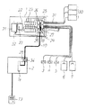
図1は本発明の住宅監視システムの外観図であり、1は分電盤、2はインターホンである。分電盤1には、電力計測装置、積算電力計、電圧・電流検出器、漏電検出器、過電流検出器、力率測定器等を内蔵させることができる。またこの分電盤1には、ガスセンサ3、煙センサ4、熱センサ5、ガス量計6、水道計7などの各種計測装置の少なくとも一つが接続されている。このほか、侵入者感知装置、時計、電気、ガス、水道等の料金計算器などを接続してもよい。なお、図1では各種計測装置を分電盤1の制御部8に直接接続したが、途中にセンサー盤を設けて各種計測装置を接続し、センサー盤と分電盤とを伝送手段で接続してもよい。
【0009】
インターホン2と分電盤1とは、双方向に信号を送受することができる伝送手段9によって接続されている。伝送手段9は有線・無線のいずれであってもよいが、図1ではインターホン2と分電盤1との双方に伝送制御部を設け、それらの間を伝送線10によって接続している。
【0010】
インターホン2は表示部11と操作部12とを備えている。表示部11は例えばテレビ画面であって、インターホン2が玄関等に設置された子機13と通話中には訪問者の映像を映すものであるが、非通話中には各種計測装置の計測結果を表示することができる。
【0011】
例えば分電盤1内で計測されたリアルタイムの電力消費量を表示させたい場合には、インターホン2の操作部12を人が操作して表示切替えを行うと、インターホン2の制御部14から要求信号が出力されて分電盤1の制御部8に伝送され、制御部8に接続された電力計からリアルタイムの電力消費量の信号が伝送手段9を介して返信される。返信信号が正常に届いた場合には肯定信号が制御部14から制御部8へ送られるとともに、インターホン2の表示部11にリアルタイムの電力消費量が表示される。
【0012】
このほか分電盤1の情報としては、月単位の積算電力量、週単位の積算電力量、日単位の積算電力量、ピーク電力量、電力警告設定値等があり、これらはインターホン2の操作部12を操作して表示切替えを行うことにより、表示部11に表示される。また同様の操作により、分電盤1の制御部8に接続されているガスセンサ3、煙センサ4、熱センサ5、ガス量計6、水道計7などの各種計測装置の計測結果も表示部11に表示させることができる。
【0013】
なお、操作部12を人が操作して表示部11の表示内容を切り替えるほか、各種計測装置の表示内容を自動切替えするように操作部12から設定しておくこともできる。もちろん、警告出力があるときには他の情報を表示中であっても自動切替えにより警告表示を行うことが好ましい。
【0014】
また、上記のようにインターホン2の操作部12を操作して表示切替えを行うことによって、分電盤1の制御部8からは各種データがインターホン2に送信されてくるが、切替えを頻繁に行うと伝送装置が飽和してしまうおそれがあるため、インターホン2には重要度の低い各種データを短略化して伝送することが好ましい。例えば、電気、ガス、水道の使用量を「大」、「中」、「小」を意味する「F」、「M」、「S」等の一文字のデータに置き換えて送信し、インターホン2の表示部11には使用量「大」、「中」、「小」のみをリアルタイムに表示する。このようにすれば、伝送装置に負担をかけず使用状態をリアルタイムに表示することができる。実際の使用量を表すデータは比較的長い時間間隔で送ればよい。
【0015】
なお、上記した各種計測装置は分電盤1の制御部8に接続されているが、各入力部にディップスイッチ等によりアドレスを設定し、計測装置の増設に対応できるようにしておくことが好ましい。
【0016】
また本発明においては、分電盤1の制御部8に接続した各種計測装置への設定情報をインターホン2の操作部12から入力できるようにしておく。具体的には使用電圧、線様式、ブレーカの定格電流、カレンダーの設定、時刻設定等である。また月、週、日単位の電力警告を行う値の設定、月毎の電力積算の開始日の設定、電力料金積算値の設定などの料金関係の設定も含まれる。これによって、従来のように各種計測装置の設置場所まで行かなくても、設定情報の入力が可能となる。
【0017】
さらに、インターホン2の操作部12は各種計測装置に優先順位を設定可能であり、インターホン2に内蔵された制御部14は、記憶装置に計測結果を一時的に保持し、優先順位に従って信号を処理することが可能である。すなわち、一定時間内にインターホン2が受信した信号は、その計測結果を記憶装置に一時的に保持し、制御部14は一定時間間隔で優先順位に従ってより緊急度の高い信号を表示し処理するものである。例えば、過電流警報と煙センサーからの警告信号では、より緊急度の高い煙センサーからの警告信号をインターホンに表示し、図示しないスピーカより警報を発するものである。また、優先順位は使用者および使用状況によって異なるため、インターホンの操作部より設定することができる。
【0018】
上記の説明では単一の分電盤1と単一のインターホン2が接続されていたが、分電盤1やインターホン2が複数個存在する場合には、インターホン2及び分電盤1に固有の装置識別番号を持たせ、信号を送信する時に装置識別番号を同時に送信する。これにより1つのインターホン2で別の場所にある複数の分電盤1,1の状態を操作、監視でき、また重要な分電盤1については、複数の場所からインターホン2により操作、監視できるようになる。
【0019】
図2は上記の機能を得るための内部構成の一例を示す図である。
分電盤1の内部には従来と同様に電流制限器21、主幹ブレーカ22、分岐ブレーカ23等が配置されているほか、不揮発メモリ24、デジタル出力部25、アナログ入力部26、デジタル入力部27、双方向インターフェイス28を備えた伝送制御部29が設けられている。これらは前記した制御部8を構成するものである。
【0020】
デジタル出力部25には、電灯等の負荷30が電源供給線31を介して接続されている。アナログ入力部26には、分電盤内部の電圧情報、負荷電流検出器32により検出された負荷電流情報、主幹ブレーカ22の警報スイッチ33により検出された警報情報などが入力されている。デジタル入力部27には、各所計測機器からの計測値が入力されている。これらの情報は伝送制御部29から伝送線10を介してインターホン2の伝送制御部34に送信され、また逆にインターホン2からの信号を受信することができる。
【0021】
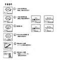
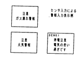
図3〜図5はインターホン2の表示部11の表示例を示す図である。図3は子機13との通話が行われていない状態において、電気、ガス、水道等の使用量を自動表示するもので、▲1▼は1日の使用電力料金の表示、▲2▼は1月毎の使用電力料金、ガス料金、水道料金の表示、▲3▼は積算電力料金、ガス料金、水道料金の表示、▲4▼は昨年の月別使用電力量の表示、▲5▼はグラフによる節電お知らせの表示、▲6▼は現在の使用電力が許容限界の何%程度であるかを示す停電お知らせの表示である。これらの▲1▼〜▲6▼の内容は、自動的にまたは操作部12からの操作により切り替えて表示される。図4は各種計測装置が異常を検知したときの表示例であり、図5は非常時における連動出力の表示例である。これらの非常時の表示は割り込み信号により優先表示される。
【0022】
【発明の効果】
以上に説明したように、本発明の住宅監視システムによれば、インターホンの表示部に各種計測装置の計測結果を表示するため、人が居る可能性の高いところで電気、ガス、水道等を監視することができ、省エネの意識を喚起することができる。またインターホンから各種計測センサーの設定変更が可能であるので、従来のように各種計測装置の設置場所まで行って設定情報を入力する必要がない。さらに、各種計測装置に優先順位を付与できるため、緊急度の高い信号の順に処理することができる。また分電盤に各種センサーを全て接続したため、インターホンの移設が容易である上、インターホンを無線化し携帯することが可能となる。更に複数の分電盤の状態を1つのインターホンで監視することが可能となり、また1つの分電盤を複数のインターホンで監視することも可能となる等の多くの利点がある。
【図面の簡単な説明】
【図1】本発明の実施形態を示す住宅監視システムの外観図である。
【図2】本発明の実施形態を示す内部構成図である。
【図3】平常時における表示部の表示例を示す図である。
【図4】各種計測装置が異常を検知したときの表示例である。
【図5】非常時における連動出力の表示例である。
【符号の説明】
1 分電盤
2 インターホン
3 ガスセンサ
4 煙センサ
5 熱センサ
6 ガス量計
7 水道計
8 分電盤の制御部
9 伝送手段
10 伝送線
11 インターホンの表示部
12 インターホンの操作部
13 インターホンの子機
14 インターホンの制御部
21 電流制限器
22 主幹ブレーカ
23 分岐ブレーカ
24 不揮発メモリ
25 デジタル出力部
26 アナログ入力部
27 デジタル入力部
28 双方向インターフェイス
29 分電盤の伝送制御部
30 負荷
31 電源供給線
32 負荷電流検出器
33 警報スイッチ
34 インターホンの伝送制御部[0001]
BACKGROUND OF THE INVENTION
The present invention relates to a house monitoring system using an intercom.
[0002]
[Prior art]
The distribution board installed in the house has built-in measurement sensors such as electric power, overcurrent, and electric leakage, so that the measurement results can be displayed and alarms can be performed. However, since these indications are always performed inside the distribution board installed in a place away from the living room where people are present, the display of the measurement results and alarms can be viewed up to the distribution board. I had to go to, and sometimes I was not aware of the alarm.
[0003]
On the other hand, connecting to a detection device such as a gas leak or fire to issue an alarm, connecting various measuring devices such as gas / water integrated flow meters to display their integrated values, or displaying usage charges Combining house information boards with intercoms installed in living rooms and kitchens.
[0004]
However, even if such a housing information board is used, conventionally, the setting change of various measuring devices has to be performed at the installation location of each measuring device. This setting includes, for example, setting of contract capacity, setting of a warning value related to power consumption, setting of a power charge integrated value, setting of time used in the measuring device, and the like. In addition, the conventional housing information panel is connected to various measuring devices such as gas leaks and fire detection devices and gas / water flow meter, so once installed, it is not easy to relocate. Wireless communication was also difficult.
[0005]
[Problems to be solved by the invention]
The present invention solves the above-described conventional problems, and uses an intercom installed in the living room to display not only electrical displays and alarms, but also displays and accumulated charges for various measuring devices such as power, gas, and water. The present invention has been made to provide a home monitoring system that can be known and can also change the settings of various measuring devices. Another object of the present invention is to provide a house monitoring system in which an interphone can be easily relocated and wireless. Still another object of the present invention is to provide a house monitoring system capable of appropriately performing the above operation and display even when a plurality of distribution boards and intercoms are present.
[0006]
[Means for Solving the Problems]
The house monitoring system of the present invention made to solve the above problems is a distribution board connected to various measuring devices, an interphone provided with a display unit and an operation unit capable of displaying the measurement results of the various measuring devices, and a transmitting means for transmitting and receiving signals between interphone and distribution board, the operation unit of the intercom, with a possible switching of Viewing contents of the display unit is a measurement result various measuring devices, the distribution board Setting information for various measuring devices connected to the control unit can be input to the control unit of the distribution board via the transmission means . The operation of the in-Tahon is configurable priority to various measuring devices, together with a control unit incorporated in the intercom stores the measurement result in the storage means, it is intended to process the signals according to priority preferable.
[0007]
In the house monitoring system of the present invention, the distribution board to which various measuring devices are connected and the interphone are connected via the transmission means, and the measurement results of the various measuring devices can be displayed on the display unit of the interphone. The display contents of the display unit can be switched from the operation unit, and settings of various measuring devices can be changed. In other words, it is possible to change the settings of various measuring devices connected to the distribution board by sending signals to the distribution board from the operation unit of the interphone, and to request and display the output signals of various measuring devices. It is also possible to switch the display content of the part. Therefore, the resident can obtain necessary information from the various measuring devices installed in the house through the display unit of the interphone installed in the living room or the like, and can perform all operations from the intercom.
[0008]
DETAILED DESCRIPTION OF THE INVENTION
Hereinafter, preferred embodiments of the present invention will be described.
FIG. 1 is an external view of a housing monitoring system according to the present invention, where 1 is a distribution board and 2 is an intercom. The distribution board 1 can incorporate a power measuring device, an integrating wattmeter, a voltage / current detector, a leakage detector, an overcurrent detector, a power factor measuring device, and the like. The distribution board 1 is connected to at least one of various measuring devices such as a
[0009]
The
[0010]
The
[0011]
For example, when it is desired to display the real-time power consumption measured in the distribution board 1, when a user operates the
[0012]
Other information on the distribution board 1 includes monthly integrated electric energy, weekly integrated electric energy, daily integrated electric energy, peak electric energy, power warning setting value, etc. The
[0013]
In addition to switching the display content of the
[0014]
In addition, by switching the display by operating the
[0015]
The various measuring devices described above are connected to the control unit 8 of the distribution board 1. However, it is preferable to set an address to each input unit by using a dip switch or the like so that the measuring device can be expanded. .
[0016]
Further, in the present invention, setting information for various measuring devices connected to the control unit 8 of the distribution board 1 can be input from the
[0017]
Furthermore, the
[0018]
In the above description, a single distribution board 1 and a
[0019]
FIG. 2 is a diagram showing an example of an internal configuration for obtaining the above function.
In the distribution board 1, a
[0020]
A load 30 such as an electric lamp is connected to the
[0021]
3 to 5 are diagrams showing display examples of the
[0022]
【The invention's effect】
As described above, according to the house monitoring system of the present invention, since the measurement results of various measuring devices are displayed on the display unit of the intercom, electricity, gas, water supply, etc. are monitored where there is a high possibility of being present. Can raise awareness of energy conservation. In addition, since it is possible to change the settings of various measurement sensors from the interphone, it is not necessary to go to the installation location of various measurement devices and input the setting information as in the past. Furthermore, since priority can be given to various measuring devices, it is possible to process signals in the order of urgency. In addition, since all the sensors are connected to the distribution board, it is easy to move the interphone, and the interphone can be wirelessly carried. Furthermore, there are many advantages such as the state of a plurality of distribution boards can be monitored with one intercom, and the one distribution board can be monitored with a plurality of interphones.
[Brief description of the drawings]
FIG. 1 is an external view of a house monitoring system showing an embodiment of the present invention.
FIG. 2 is an internal configuration diagram showing an embodiment of the present invention.
FIG. 3 is a diagram illustrating a display example of a display unit in a normal state.
FIG. 4 is a display example when various measuring apparatuses detect an abnormality.
FIG. 5 is a display example of interlocking output in an emergency.
[Explanation of symbols]
DESCRIPTION OF SYMBOLS 1
Claims (2)
Priority Applications (1)
| Application Number | Priority Date | Filing Date | Title |
|---|---|---|---|
| JP2001107960A JP3904404B2 (en) | 2001-04-06 | 2001-04-06 | Housing monitoring system |
Applications Claiming Priority (1)
| Application Number | Priority Date | Filing Date | Title |
|---|---|---|---|
| JP2001107960A JP3904404B2 (en) | 2001-04-06 | 2001-04-06 | Housing monitoring system |
Publications (3)
| Publication Number | Publication Date |
|---|---|
| JP2002305597A JP2002305597A (en) | 2002-10-18 |
| JP2002305597A5 JP2002305597A5 (en) | 2005-05-12 |
| JP3904404B2 true JP3904404B2 (en) | 2007-04-11 |
Family
ID=18960189
Family Applications (1)
| Application Number | Title | Priority Date | Filing Date |
|---|---|---|---|
| JP2001107960A Expired - Fee Related JP3904404B2 (en) | 2001-04-06 | 2001-04-06 | Housing monitoring system |
Country Status (1)
| Country | Link |
|---|---|
| JP (1) | JP3904404B2 (en) |
Families Citing this family (10)
| Publication number | Priority date | Publication date | Assignee | Title |
|---|---|---|---|---|
| JP2007266705A (en) * | 2006-03-27 | 2007-10-11 | Aiphone Co Ltd | Home interphone system |
| JP2009290347A (en) * | 2008-05-27 | 2009-12-10 | Panasonic Electric Works Co Ltd | Intercom system and intercom master unit |
| JP2010288227A (en) * | 2009-06-15 | 2010-12-24 | Panasonic Electric Works Co Ltd | Intercom system |
| EA027503B1 (en) * | 2010-07-02 | 2017-08-31 | Белкин Интернэшнл, Инк. | Systems and methods for measuring electrical power usage in a structure and systems and methods of calibrating the same |
| JP5874025B2 (en) * | 2010-08-05 | 2016-03-01 | パナソニックIpマネジメント株式会社 | Remote meter reading system, information terminal, communication device, distribution board |
| JP5923741B2 (en) * | 2010-11-15 | 2016-05-25 | パナソニックIpマネジメント株式会社 | Intercom system for housing complex |
| JP5816860B2 (en) * | 2011-03-22 | 2015-11-18 | パナソニックIpマネジメント株式会社 | Intercom device and intercom system using the same |
| JP6478081B2 (en) * | 2013-05-20 | 2019-03-06 | パナソニックIpマネジメント株式会社 | Housing information board, measuring unit, and energy measuring system including them |
| JP6264684B2 (en) * | 2013-11-05 | 2018-01-24 | パナソニックIpマネジメント株式会社 | Distribution board and cabinet for distribution board |
| JP5891445B2 (en) * | 2014-06-18 | 2016-03-23 | パナソニックIpマネジメント株式会社 | Remote meter reading system, communication device, distribution board |
-
2001
- 2001-04-06 JP JP2001107960A patent/JP3904404B2/en not_active Expired - Fee Related
Also Published As
| Publication number | Publication date |
|---|---|
| JP2002305597A (en) | 2002-10-18 |
Similar Documents
| Publication | Publication Date | Title |
|---|---|---|
| US4804957A (en) | Utility meter and submetering system | |
| KR101597096B1 (en) | Real-time remote measurement of vibration and leakage currents and switchboards with external intrusion prevention and data storage | |
| JP3904404B2 (en) | Housing monitoring system | |
| JP2010128617A (en) | Usage monitoring system | |
| JPWO2006004112A1 (en) | Power consumption measuring device and power management system | |
| JP2000193695A (en) | Electric power using state monitoring method and its device | |
| CN103071269A (en) | Novel automatic fire-fighting terminal water testing system | |
| JP5173356B2 (en) | Power management system | |
| JP2007304913A (en) | Radio meter reading system | |
| JPH11261714A (en) | Equipment information network system | |
| JP2784354B2 (en) | Saving rate display | |
| JP6573246B1 (en) | Lifeline usage management system, lifeline usage management method, program | |
| EP0834849A1 (en) | Metering Apparatus | |
| JP2009174895A (en) | Gas meter system | |
| JP5725926B2 (en) | Energy monitoring system | |
| JP6454878B2 (en) | Usage monitoring system | |
| JP2007232682A (en) | Apparatus and system for centralized meter reading system | |
| KR0148643B1 (en) | The integrated system for electricity, water, gas meter | |
| KR20020011002A (en) | A multi-measurement single remote telemetering system | |
| JPH03150698A (en) | System for deciding abnormality of resident from using condition of water or electricity | |
| JP2006084180A (en) | Electric energy sensor and security system utilizing it | |
| JP2003044971A (en) | Instrument and system for measurement | |
| JP2014112423A (en) | Consumption monitoring system and consumption monitoring unit | |
| KR20040014100A (en) | Development of digital wattmeter for module type remote metering function | |
| CN106410644A (en) | Vehicle mobile transformer substation levelness abnormity monitoring device |
Legal Events
| Date | Code | Title | Description |
|---|---|---|---|
| A521 | Written amendment |
Free format text: JAPANESE INTERMEDIATE CODE: A523 Effective date: 20040625 |
|
| A621 | Written request for application examination |
Free format text: JAPANESE INTERMEDIATE CODE: A621 Effective date: 20040625 |
|
| A131 | Notification of reasons for refusal |
Free format text: JAPANESE INTERMEDIATE CODE: A131 Effective date: 20060516 |
|
| A521 | Written amendment |
Free format text: JAPANESE INTERMEDIATE CODE: A523 Effective date: 20060710 |
|
| TRDD | Decision of grant or rejection written | ||
| A01 | Written decision to grant a patent or to grant a registration (utility model) |
Free format text: JAPANESE INTERMEDIATE CODE: A01 Effective date: 20070109 |
|
| A61 | First payment of annual fees (during grant procedure) |
Free format text: JAPANESE INTERMEDIATE CODE: A61 Effective date: 20070109 |
|
| R150 | Certificate of patent or registration of utility model |
Ref document number: 3904404 Country of ref document: JP Free format text: JAPANESE INTERMEDIATE CODE: R150 Free format text: JAPANESE INTERMEDIATE CODE: R150 |
|
| FPAY | Renewal fee payment (event date is renewal date of database) |
Free format text: PAYMENT UNTIL: 20130119 Year of fee payment: 6 |
|
| R250 | Receipt of annual fees |
Free format text: JAPANESE INTERMEDIATE CODE: R250 |
|
| FPAY | Renewal fee payment (event date is renewal date of database) |
Free format text: PAYMENT UNTIL: 20130119 Year of fee payment: 6 |
|
| FPAY | Renewal fee payment (event date is renewal date of database) |
Free format text: PAYMENT UNTIL: 20160119 Year of fee payment: 9 |
|
| R250 | Receipt of annual fees |
Free format text: JAPANESE INTERMEDIATE CODE: R250 |
|
| R250 | Receipt of annual fees |
Free format text: JAPANESE INTERMEDIATE CODE: R250 |
|
| R250 | Receipt of annual fees |
Free format text: JAPANESE INTERMEDIATE CODE: R250 |
|
| LAPS | Cancellation because of no payment of annual fees |