JP3899805B2 - Mounting member for fall prevention member and mounting structure thereof - Google Patents
Mounting member for fall prevention member and mounting structure thereof Download PDFInfo
- Publication number
- JP3899805B2 JP3899805B2 JP2000371497A JP2000371497A JP3899805B2 JP 3899805 B2 JP3899805 B2 JP 3899805B2 JP 2000371497 A JP2000371497 A JP 2000371497A JP 2000371497 A JP2000371497 A JP 2000371497A JP 3899805 B2 JP3899805 B2 JP 3899805B2
- Authority
- JP
- Japan
- Prior art keywords
- fall prevention
- prevention member
- mounting
- support
- fall
- Prior art date
- Legal status (The legal status is an assumption and is not a legal conclusion. Google has not performed a legal analysis and makes no representation as to the accuracy of the status listed.)
- Expired - Lifetime
Links
Images


Landscapes
- Display Racks (AREA)
Description
【0001】
【発明の属する技術分野】
本発明は落下防止部材の取付具及びその取付構造に係り、更に詳しくは、支持体に設けられた棚板装着用の穴を利用して背当て板等の落下防止部材を棚板後端側に位置するように取り付けることができる落下防止部材の取付具及びその取付構造に関する。
【0002】
【従来の技術】
公知の陳列棚は、前後及び左右一対の支柱と、これら支柱内に配置された棚板とを備えて構成されている。支柱には、その上下方向に沿って所定間隔毎に取付穴が形成されており、この取付穴にフック金具を引っ掛けて棚板を所定の高さ位置にセットできるようになっている。また、棚板の後端側には、当該棚板上に載せられた陳列対象物の後方への落下を規制するための、背当て板等の細長い落下防止部材を装着する場合が多い。このような落下防止部材を棚板の後端側に位置するように取り付ける場合には、従来では、後部に位置する左右の支柱の後面に取付穴を形成しておき、この取付穴を利用して落下防止部材を引っ掛けてこれを支持させる手法が採用されている。
【0003】
【発明が解決しようとする課題】
しかしながら、このような構造にあっては、各支柱の二面に取付穴を設ける構造となるため、前面側若しくは後面側に取付穴が目立って見えてしまうものとなり、外観上の体裁を大きく損なう原因となる。しかも、支柱に多数の取付穴を設けると、当該支柱自体の強度が低下するという不都合を招来する。また、落下防止部材を取り付けしたい位置に対応して適正位置に取付穴が設けられていない場合も生じ、従って、棚板の高さ位置を変更したときに、これに柔軟に対応できなくなるという不都合もある。
【0004】
【発明の目的】
本発明は、このような不都合に着目して案出されたものであり、その目的は、棚部材を支持するための取付穴を利用して落下防止部材を取り付けできるようにし、取付穴が支柱の前面側若しくは後面側に表出しないタイプのものを利用できる落下防止部材の取付具及びその取付構造を提供することにある。
【0005】
【課題を解決するための手段】
前記目的を達成するため、本発明は、相対する取付面に棚部材支持用の取付穴が設けられた一対の支持体を利用して当該支持体間に落下防止部材を取り付けるための取付具において、
前記落下防止部材の端部に一体若しくは別体に設けられて前記取付穴に引っ掛け可能な掛け部を備えた第1の部材と、この第1の部材に連なるとともに前記落下防止部材の支持部を備えた第2の部材とからなり、当該第2の部材は、第1の部材に対して屈曲した方向に延びる、という構成を採っている。このような構成とすれば、落下防止部材を取り付けるための専用の取付穴を設けることなく落下防止部材を取り付けることが可能となる。しかも、棚部材装着用の取付穴を利用している構造であるため、棚部材の高さ位置を変更しても当該棚部材の位置に常に対応して落下防止部材を取り付けることができる。
【0006】
また、本発明は、相互に所定間隔を隔てて配置された支持体に取付具を介して落下防止部材を取り付ける構造において、
前記支持体は、横断面略L字状の支柱により構成されるとともに、当該L字の一方の面が前後方向に沿って配置されるとともに、上下方向に沿って所定間隔毎に取付穴が設けられ、
前記取付具は、前記落下防止部材の端部に一体若しくは別体に設けられて前記取付穴に引っ掛け可能な掛け部を備えた第1の部材と、この第1の部材に連なるとともに前記落下防止部材の支持部を備えた第2の部材とからなり、当該第2の部材は、第1の部材に対して屈曲した方向に延びる、という構成を採っている。このような構成とすれば、支柱の側面側に取付穴が位置することとなり、前面側若しくは後面側に取付具の掛け部が表れるようなことはない。
【0007】
【発明の実施の形態】
本発明に係る落下防止部材の取付具の第2の部材は、前記落下防止部材の後面側に位置可能に設けられる、という構成を採用することができる。これにより、第2の部材が落下防止部材の後ろに隠れる状態となり、落下防止部材の前面側若しくは内面側に段差を生じさせることを防止可能となる。この際、掛け部と支持部の高さ位置が異なって設けられるようにするとよく、これにより、落下防止部材と、支柱に支持される棚部材との位置的な相互干渉を容易に防止することができる。
【0008】
また、本発明に係る落下防止部材の取付構造において、前記支柱の他方の面は穴を有しない面に形成される、という構造を採っている。これにより、支柱の前面側若しくは後面側に取付穴を表出させない構造とすることができ、外観上の体裁を良好に保つことが可能となる。
【0009】
前記取付構造において、取付具の第2の部材は、前記支柱の他方の面に沿って位置するとともに、内面側に前記落下防止部材の支持部が設けられて当該支持部に落下防止部材が支持可能に設けられる、という構成とすることが好ましい。
【0010】
更に、前記落下防止部材を長さ調整可能に設けるとよい。このような長さ可変型とすれば、支柱間距離が異なる各種タイプのものに落下防止部材を共通部品として適用することができる。
【0011】
【実施例】
以下、本発明の実施例を図面を参照しながら説明する。
【0012】
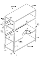
図1には、本発明が陳列棚に適用された実施例に係る概略斜視図が示され、図2には、図1のA部を拡大した概略分解斜視図が示されている。これらの図において、陳列棚10は、前後及び左右二箇所に相対配置された支持体としての支柱11と、当該支柱11の下端側及び上端側に設けられたベース板12及び天板13と、これらベース板12及び天板13間に設けられた棚部材としての棚板15と、各棚板15の後端側に装着されて落下防止部材として作用する背当て板16とを備えて構成されている。
【0013】
前記支柱11は、横断面形状が略L字状となる屈曲タイプのものが採用され、当該L字の屈曲部がコーナーに位置する向きで配置されている。すなわち、前部二本の支柱11は、左右方向に沿う面となる前面部11Aと、前後方向に沿う面となる前部側面部11Bを有する一方、後部二本の支柱11は、左右方向に沿って位置するとともに前記前面部11Aと略平行に位置する後面部11Cと、前後方向に沿って位置し、且つ、前部側面部11Bと略同一の鉛直面内に位置する後部側面部11Dとを有する。前面部11A及び後面部11Cは穴を有しない面として形成されている。また、前部側面部11B及び後部側面部11Dは、上下方向に沿って略等ピッチ間隔を隔てて棚部材支持用の多数の取付穴20が形成されている。
【0014】
前記ベース板12、天板13は、ここでは図示しない公知の取付部材を介して支柱11の下端側と上端側にそれぞれ固定されている。また、棚板15は、図3に示されるように、前記取付穴20に引っ掛け可能な公知のフック金具22を介して高さ位置調整可能に支持されている。
【0015】
前記背当て板16は、図2ないし図4に示されるように、後部側に位置する支柱11の相対する取付面、すなわち、後部側面部11Dの取付穴20に引っ掛けられる取付具24を介して左右の支柱11間に掛け渡される状態で取り付けられている。この取付具24は、支柱11における後部側面部11Dの内面側に沿って位置可能な第1の部材25と、この第1の部材25に対し、当該第1の部材25の面と略直交する方向に連なるとともに、後面部11Cの内面側に沿って位置可能な第2の部材26とにより構成されている。
【0016】
前記第1の部材25は、その面内略中央部において、上下二箇所位置を切り起こして形成された掛け部としての下向き舌片28,28を備え、また、第2の部材も、上下二箇所位置を切り起こして形成された支持部としての上向き舌片29を備えて構成されている。下向き舌片28は、前記取付穴20内に挿入されて当該取付穴20の下端形成縁に引っ掛けられるようになっている。なお、前記第2の部材26は、その下部一側縁が第1の部材25の一側縁に連なり、第2の部材26の上部は、第1の部材25の上端縁よりも上方に位置するように設けられ、これにより、下向き舌片28と上向き舌片29の高さ位置が異なる高さ位置となり、背当て板16の取付位置と棚板15の取付位置とが相互に干渉しないようになっている。
【0017】
前記背当て板16は、左右方向に長い板状をなし、その上端及び下端には、板状素材を折返す板金加工によって形成された補強部16Aが上下二箇所に設けられている。この背当て板16の長手方向両側には、上下二箇所に支持穴30,30が形成され、これらの支持穴30内に前記上向き舌片29が挿入されるようになっている。
【0018】
以上の構成において、背当て板16を取り付ける場合には、後ろ二本の支柱11に対し、取付具24の下向き舌片28を取付穴20に挿入してこれに引っ掛ける。これにより、第2の部材26は、支柱11の後面部11Cの内面側に沿う位置となる。この後、第2の部材26に設けられた上向き舌片29を背当て板16の支持穴30に挿入すればよい。なお、背当て板16の取り付けに前後して、当該背当て板16に対応する棚板15がフック金具22を介して所定の高さ位置に取り付けられる。
【0019】
従って、このような実施例によれば、棚板15を支持するための取付穴20を利用して背当て板16を装着するための取付具24を引っ掛けることができるように設けたから、当該取付具24を介して背当て板16を棚板15の後端側に極めて容易且つ迅速に取り付けることが可能となる。
【0020】
なお、前記実施例では、取付具24が第1及び第2の部材25,26により構成され、且つ、背当て板16と別体に構成された場合を図示説明したが、本発明はこれに限定されるものではない。例えば、図5に示されるように、背当て板16の長手方向両端部の上下二箇所に下向き舌片28を一体に設けた構成としてもよい。これによれば、背当て板16の面内に前述した支持穴30を設ける必要をなくすことができる。また、背当て板16は、図5中左右方向に沿って相互にスライド移動可能な第1及び第2の背当て板30,31の組み合わせとしてもよく、これにより、長さ調整を可能として支柱11間距離が種々異なるタイプの陳列棚に適用することができる。なお、図5に示すタイプの補強部16Aは、断面略L字状の折り曲げ部とし、第1の背当て板30側の補強部16A内に第2の背当て板31の補強部16Aを受容する相対形状とすることで、これらをガイド部材として利用することが可能となる。
【0021】
また、前記実施例では、落下防止部材として板状をなす背当て板16を図示、説明したが、棚板15上に陳列される対象物の落下を防止し得る形状である限り、ネット状の部材等も採用することができる。
【0022】
【発明の効果】
以上説明したように、本発明の取付具は、落下防止部材の端部に一体若しくは別体に設けられ、支持体における棚部材支持用の取付穴に引っ掛け可能な掛け部を備えた構成とされているため、落下防止部材を取り付けるための専用の取付穴を設けることなく落下防止部材を取り付けることが可能となる。しかも、棚部材装着用の取付穴を利用している構造であるため、棚部材の高さ位置を変更しても当該棚部材の位置に常に対応して落下防止部材を取り付けることができる。
【0023】
また、前記取付具を第1及び第2の部材により構成するとともに、当該第2の部材が第1の部材に対して屈曲した方向に延びて落下防止部材の後面側に位置する構成としたから、第2の部材が落下防止部材の後ろに隠れる状態となり、落下防止部材の前面側に段差を生じさせることがない。また、掛け部と支持部の高さ位置が異なって設けられた場合には、落下防止部材と、支柱に支持される棚部材との位置的な相互干渉を生じない設計が容易となる。
【0024】
また、本発明に係る落下防止部材を取り付ける構造は、横断面略L字状の支柱により支持体が構成され、当該L字の一方の面をなす前後方向に沿う面内に取付穴が設けられ、この取付穴に引っ掛け可能な掛け部を有する取付具が落下防止部材の端部に一体若しくは別体に設けられる構成とされているため、支柱の側面側に取付穴が位置することとなり、前面側若しくは後面側に取付具の引っ掛け部が表れるようなことはない。
【0025】
また、前記支柱の他方の面は穴を有しない面に形成されているため、支柱の前面側若しくは後面側に取付穴を表出させない構造とすることができ、外観上の体裁を良好に保つことが可能となる。
【0026】
更に、前記落下防止部材を長さ調整可能とした場合には、支柱間距離が異なる各種タイプのものに落下防止部材を共通部品として適用することができる。
【図面の簡単な説明】
【図1】 実施例に係る陳列棚の概略斜視図。
【図2】 図1のA部拡大分解斜視図。
【図3】 背当て板の取付状態を示す部分断面前面図。
【図4】 図3のB−B線に沿う断面図。
【図5】 取付具の変形例を示す要部前面図。
【符号の説明】
10 陳列棚
11 支柱(支持体)
11C 後面部
11D 後部側面部
15 棚板(棚部材)
16 背当て板(落下防止部材)
20 取付穴
24 取付具
25 第1の部材
26 第2の部材
28 下向き舌片(掛け部)
29 上向き舌片(支持部)
30 支持穴[0001]
BACKGROUND OF THE INVENTION
The present invention relates to a mounting member for a fall prevention member and its mounting structure, and more specifically, the fall prevention member such as a back plate is placed on the rear end side of the shelf board using a shelf mounting hole provided in the support. The present invention relates to a mounting member for a fall prevention member that can be mounted so as to be positioned at a position and a mounting structure thereof.
[0002]
[Prior art]
A known display shelf is configured to include a pair of front and rear and left and right columns and shelf plates disposed in these columns. Mounting holes are formed at predetermined intervals along the vertical direction of the support columns, and the shelf can be set at a predetermined height position by hooking hook metal fittings into the mounting holes. In many cases, an elongate fall prevention member such as a back plate is attached to the rear end side of the shelf board in order to restrict the fall of the display object placed on the shelf board. In the case of mounting such a fall prevention member so as to be positioned on the rear end side of the shelf board, conventionally, mounting holes are formed on the rear surfaces of the left and right support columns positioned at the rear, and this mounting hole is used. A method of hooking the fall prevention member and supporting it is adopted.
[0003]
[Problems to be solved by the invention]
However, in such a structure, since the mounting holes are provided on the two surfaces of each support column, the mounting holes are conspicuously visible on the front side or the rear side, which greatly impairs the appearance. Cause. In addition, when a large number of mounting holes are provided in the support column, there is a disadvantage that the strength of the support column itself is lowered. In addition, there may be a case where the mounting hole is not provided at an appropriate position corresponding to the position where the fall prevention member is to be mounted, and therefore, when the height position of the shelf board is changed, it is not possible to flexibly cope with this. There is also.
[0004]
OBJECT OF THE INVENTION
The present invention has been devised by paying attention to such inconveniences, and the purpose thereof is to enable attachment of a fall prevention member using an attachment hole for supporting a shelf member, and the attachment hole is a support column. It is an object of the present invention to provide a mounting member for a fall prevention member and a mounting structure for the same that can be used on the front side or the rear side.
[0005]
[Means for Solving the Problems]
In order to achieve the above object, the present invention provides a fixture for mounting a fall prevention member between a pair of supports using a pair of supports provided with mounting holes for supporting shelf members on opposing mounting surfaces. ,
A first member provided with a hook portion that is integrally or separately provided at an end portion of the fall prevention member and can be hooked in the mounting hole, and a support portion for the fall prevention member that is connected to the first member. The second member includes a second member, and the second member extends in a direction bent with respect to the first member . With such a configuration, the fall prevention member can be attached without providing a dedicated attachment hole for attaching the fall prevention member. And since it is the structure using the attachment hole for shelf member mounting | wearing, even if it changes the height position of a shelf member, a fall prevention member can always be attached corresponding to the position of the said shelf member.
[0006]
Further, the present invention is a structure for attaching a fall prevention member to a support body arranged at a predetermined interval from each other via a fixture,
The support is composed of a support column having a substantially L-shaped cross section, and one surface of the L-shape is disposed along the front-rear direction, and mounting holes are provided at predetermined intervals along the vertical direction. And
The fixture is provided with a first member provided integrally or separately on an end portion of the fall prevention member and provided with a hook portion that can be hooked in the attachment hole, and is connected to the first member and the fall prevention device. The second member is provided with a member supporting portion, and the second member extends in a direction bent with respect to the first member . In such a configuration, it becomes possible to position the mounting holes on the side surface side of the column, it does not like pawl in place of the fixture appears on the front side or rear side.
[0007]
DETAILED DESCRIPTION OF THE INVENTION
The 2nd member of the fixture of the fall prevention member which concerns on this invention can employ | adopt the structure that it is provided in the rear surface side of the said fall prevention member so that a position is possible. Accordingly, the second member is hidden behind the fall prevention member, and it is possible to prevent a step from being generated on the front side or the inner side of the fall prevention member. At this time, it is preferable that the height positions of the hanging portion and the support portion are different from each other, thereby easily preventing positional mutual interference between the fall prevention member and the shelf member supported by the support column. Can do.
[0008]
Moreover, in the attachment structure of the fall prevention member according to the present invention, the other surface of the support column is formed on a surface having no hole. Thereby, it can be set as the structure which does not expose an attachment hole in the front side or rear surface side of a support | pillar, and it becomes possible to maintain the appearance on an external appearance favorably.
[0009]
In the mounting structure, the second member of the fixture is adapted to lie along the other surface of the strut, the fall preventing member supporting portion of the fall preventing member is provided on the inner side of the support portion supporting It is preferable that the configuration be provided.
[0010]
Furthermore, the fall prevention member may be provided so that its length can be adjusted. With such a variable length type, the fall prevention member can be applied as a common part to various types having different distances between the columns.
[0011]
【Example】
Embodiments of the present invention will be described below with reference to the drawings.
[0012]
FIG. 1 is a schematic perspective view according to an embodiment in which the present invention is applied to a display shelf, and FIG. 2 is a schematic exploded perspective view enlarging a part A of FIG. In these drawings, the display shelf 10 is composed of a
[0013]
The
[0014]
The base plate 12 and the top plate 13 are respectively fixed to the lower end side and the upper end side of the
[0015]
As shown in FIGS. 2 to 4, the
[0016]
The
[0017]
The
[0018]
In the above configuration, when the
[0019]
Therefore, according to such an embodiment, since the mounting
[0020]
In the above-described embodiment, the case where the
[0021]
Moreover, in the said Example, although the
[0022]
【The invention's effect】
As described above, the fixture of the present invention is configured to include a hook portion that is integrally or separately provided at the end portion of the fall prevention member and that can be hooked in the mounting hole for supporting the shelf member in the support body. Therefore, the fall prevention member can be attached without providing a dedicated attachment hole for attaching the fall prevention member. And since it is the structure using the attachment hole for shelf member mounting | wearing, even if it changes the height position of a shelf member, a fall prevention member can always be attached corresponding to the position of the said shelf member.
[0023]
In addition, the fixture is constituted by the first and second members, and the second member extends in a direction bent with respect to the first member and is positioned on the rear surface side of the fall prevention member. The second member is hidden behind the fall prevention member, and no step is generated on the front side of the fall prevention member. Moreover, when the height positions of the hanging portion and the support portion are provided differently, the design that does not cause positional mutual interference between the fall prevention member and the shelf member supported by the support column becomes easy.
[0024]
Moreover, the structure which attaches the fall prevention member which concerns on this invention comprises a support body by the support | pillar by a cross section substantially L-shaped cross section, and a mounting hole is provided in the surface along the front-back direction which makes one surface of the said L-shape. Since the fixture having a hooking portion that can be hooked in the mounting hole is configured to be provided integrally or separately at the end of the fall prevention member, the mounting hole is located on the side surface side of the column, and the front surface The hook part of the fixture does not appear on the side or rear side.
[0025]
In addition, since the other surface of the support column is formed on a surface that does not have a hole, it can be structured such that the mounting hole is not exposed on the front surface side or the rear surface side of the support column, and the appearance in appearance is kept good. It becomes possible.
[0026]
Further, when the length of the fall prevention member is adjustable, the fall prevention member can be applied as a common component to various types having different distances between the columns.
[Brief description of the drawings]
FIG. 1 is a schematic perspective view of a display shelf according to an embodiment.
FIG. 2 is an enlarged exploded perspective view of part A in FIG.
FIG. 3 is a partial cross-sectional front view showing a mounting state of a back plate.
4 is a cross-sectional view taken along line BB in FIG.
FIG. 5 is a front view of an essential part showing a modification of the fixture.
[Explanation of symbols]
10
11C
16 Back plate (fall prevention member)
20 mounting
29 Upward tongue (support)
30 Support hole
Claims (7)
前記落下防止部材の端部に一体若しくは別体に設けられて前記取付穴に引っ掛け可能な掛け部を備えた第1の部材と、この第1の部材に連なるとともに前記落下防止部材の支持部を備えた第2の部材とからなり、当該第2の部材は、第1の部材に対して屈曲した方向に延びることを特徴とする落下防止部材の取付具。In a fixture for attaching a fall prevention member between the supports using a pair of supports provided with mounting holes for supporting shelf members on the opposing mounting surfaces,
A first member provided with a hook portion that is integrally or separately provided at an end portion of the fall prevention member and can be hooked in the mounting hole, and a support portion for the fall prevention member that is connected to the first member. A fixture for a fall prevention member, comprising: a second member provided, the second member extending in a direction bent with respect to the first member .
前記支持体は、横断面略L字状の支柱により構成されるとともに、当該L字の一方の面が前後方向に沿って配置されるとともに、上下方向に沿って所定間隔毎に取付穴が設けられ、
前記取付具は、前記落下防止部材の端部に一体若しくは別体に設けられて前記取付穴に引っ掛け可能な掛け部を備えた第1の部材と、この第1の部材に連なるとともに前記落下防止部材の支持部を備えた第2の部材とからなり、当該第2の部材は、第1の部材に対して屈曲した方向に延びることを特徴とする落下防止部材の取付構造。In the structure in which the fall prevention member is attached to the supports arranged at a predetermined interval from each other via the fixture,
The support is composed of a support column having a substantially L-shaped cross section, and one surface of the L-shape is disposed along the front-rear direction, and mounting holes are provided at predetermined intervals along the vertical direction. And
The fixture is provided with a first member provided integrally or separately on an end portion of the fall prevention member and provided with a hook portion that can be hooked in the attachment hole, and is connected to the first member and the fall prevention device. An attachment structure for a fall prevention member, comprising: a second member provided with a support portion for the member, wherein the second member extends in a direction bent with respect to the first member .
Priority Applications (1)
| Application Number | Priority Date | Filing Date | Title |
|---|---|---|---|
| JP2000371497A JP3899805B2 (en) | 2000-12-01 | 2000-12-01 | Mounting member for fall prevention member and mounting structure thereof |
Applications Claiming Priority (1)
| Application Number | Priority Date | Filing Date | Title |
|---|---|---|---|
| JP2000371497A JP3899805B2 (en) | 2000-12-01 | 2000-12-01 | Mounting member for fall prevention member and mounting structure thereof |
Publications (2)
| Publication Number | Publication Date |
|---|---|
| JP2002165680A JP2002165680A (en) | 2002-06-11 |
| JP3899805B2 true JP3899805B2 (en) | 2007-03-28 |
Family
ID=18841211
Family Applications (1)
| Application Number | Title | Priority Date | Filing Date |
|---|---|---|---|
| JP2000371497A Expired - Lifetime JP3899805B2 (en) | 2000-12-01 | 2000-12-01 | Mounting member for fall prevention member and mounting structure thereof |
Country Status (1)
| Country | Link |
|---|---|
| JP (1) | JP3899805B2 (en) |
Families Citing this family (1)
| Publication number | Priority date | Publication date | Assignee | Title |
|---|---|---|---|---|
| JP5889839B2 (en) * | 2013-05-16 | 2016-03-22 | オーエッチ工業株式会社 | Shelf guard connector and shelf guard |
-
2000
- 2000-12-01 JP JP2000371497A patent/JP3899805B2/en not_active Expired - Lifetime
Also Published As
| Publication number | Publication date |
|---|---|
| JP2002165680A (en) | 2002-06-11 |
Similar Documents
| Publication | Publication Date | Title |
|---|---|---|
| US3482709A (en) | Inclined pegboard mounting displays | |
| US20050252872A1 (en) | Systems and methods for displaying articles | |
| JPH10510190A (en) | A support rod device for suspending goods to be displayed or supporting a goods display device | |
| US5749474A (en) | Bicycle display rack | |
| JP3899805B2 (en) | Mounting member for fall prevention member and mounting structure thereof | |
| JP3058100B2 (en) | Shelf support structure | |
| JP3925076B2 (en) | Shelf equipment | |
| JP3623901B2 (en) | Stable support device for self-standing partition device | |
| JP7444578B2 (en) | Support structure, fixtures and installation method | |
| JP2003289953A (en) | Shelf and bracket for receiving shelf | |
| JP5180581B2 (en) | Product display device | |
| JP3677664B2 (en) | Article fall prevention device in shelf device | |
| JP3664214B2 (en) | End frame connection structure in display shelf | |
| JP2018175484A (en) | Partition body and shelf | |
| JP3016021U (en) | Hanging hook rod device for displaying and selling merchandise | |
| JPS6235430Y2 (en) | ||
| JP4271784B2 (en) | Wiring duct device in work table | |
| JP4073159B2 (en) | Showcase | |
| JP2830752B2 (en) | Deck plate support device for display fixtures | |
| JPH07313310A (en) | Shelf plate | |
| JP4472055B2 (en) | Support structure on work table | |
| JP3110668U (en) | Display shelf equipment | |
| JP3862709B2 (en) | Display stand | |
| JPH0746199Y2 (en) | Bicycle support device | |
| JP4726317B2 (en) | Bracket mounting structure |
Legal Events
| Date | Code | Title | Description |
|---|---|---|---|
| A621 | Written request for application examination |
Free format text: JAPANESE INTERMEDIATE CODE: A621 Effective date: 20040311 |
|
| A131 | Notification of reasons for refusal |
Free format text: JAPANESE INTERMEDIATE CODE: A131 Effective date: 20060816 |
|
| A521 | Written amendment |
Free format text: JAPANESE INTERMEDIATE CODE: A523 Effective date: 20061005 |
|
| TRDD | Decision of grant or rejection written | ||
| A01 | Written decision to grant a patent or to grant a registration (utility model) |
Free format text: JAPANESE INTERMEDIATE CODE: A01 Effective date: 20061205 |
|
| A61 | First payment of annual fees (during grant procedure) |
Free format text: JAPANESE INTERMEDIATE CODE: A61 Effective date: 20061218 |
|
| R150 | Certificate of patent or registration of utility model |
Free format text: JAPANESE INTERMEDIATE CODE: R150 Ref document number: 3899805 Country of ref document: JP Free format text: JAPANESE INTERMEDIATE CODE: R150 |
|
| FPAY | Renewal fee payment (event date is renewal date of database) |
Free format text: PAYMENT UNTIL: 20100112 Year of fee payment: 3 |
|
| FPAY | Renewal fee payment (event date is renewal date of database) |
Free format text: PAYMENT UNTIL: 20110112 Year of fee payment: 4 |
|
| FPAY | Renewal fee payment (event date is renewal date of database) |
Free format text: PAYMENT UNTIL: 20120112 Year of fee payment: 5 |
|
| FPAY | Renewal fee payment (event date is renewal date of database) |
Free format text: PAYMENT UNTIL: 20130112 Year of fee payment: 6 |
|
| FPAY | Renewal fee payment (event date is renewal date of database) |
Free format text: PAYMENT UNTIL: 20130112 Year of fee payment: 6 |
|
| FPAY | Renewal fee payment (event date is renewal date of database) |
Free format text: PAYMENT UNTIL: 20140112 Year of fee payment: 7 |
|
| EXPY | Cancellation because of completion of term |