JP3898424B2 - Single piece frame joint device - Google Patents
Single piece frame joint device Download PDFInfo
- Publication number
- JP3898424B2 JP3898424B2 JP2000232047A JP2000232047A JP3898424B2 JP 3898424 B2 JP3898424 B2 JP 3898424B2 JP 2000232047 A JP2000232047 A JP 2000232047A JP 2000232047 A JP2000232047 A JP 2000232047A JP 3898424 B2 JP3898424 B2 JP 3898424B2
- Authority
- JP
- Japan
- Prior art keywords
- housing
- slide
- holder
- gap
- joint device
- Prior art date
- Legal status (The legal status is an assumption and is not a legal conclusion. Google has not performed a legal analysis and makes no representation as to the accuracy of the status listed.)
- Expired - Fee Related
Links
Images


Landscapes
- Building Environments (AREA)
Description
【0001】
【発明の属する技術分野】
本発明は、躯体間隙を介して隣接する躯体間を連結し、かつ地震などによる躯体変動に追随動作してこの躯体変動を吸収することができる躯体継手装置(エキスパンションジョイント)、中でも一枚のカバー材で躯体間隙を被閉する一枚型躯体継手装置に関する。
【0002】
【従来の技術及び発明が解決しようとする課題】
この種の躯体継手装置、すなわち一枚のカバー材で躯体間隙を被覆する一枚型の躯体継手装置には、従来、カバー材の両躯体側をバネ材等を介して可動可能に固定する両側固定タイプと、カバー材の一方をバネ材等で可動可能に固定し、他方はフリーとする片側固定タイプの2つのものがあった。
【0003】
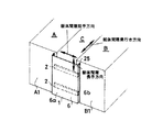
両側固定タイプの躯体継手装置としては、例えば、図19に示すように、互いの壁面が略面一に並んだ躯体Q、Rの間隙Sを壁面側から閉塞する躯体継手装置において、躯体間隙短手方向(躯体が対面する方向)に長尺な長孔101aを底面に設けてなるホルダー材101を躯体間隙Sを跨ぐように配設し、両側の壁面Q1、R1から躯体間隙S内に張り出したボルト支持部材102、102にコイルバネ103付のボルト104を躯体間隙奥行き方向に伸縮可能に装着し、このボルト104のボルト頭104aを前記ホルダー材101の長孔101aに摺動自在に挿通係合し、躯体Q,Rが躯体間隙短手方向に変動すると、長孔101a内をボルト104、104がスライドして躯体変動を吸収し、躯体間隙奥行き方向に変動すると、両側のコイルバネ103、103の伸縮を伴ったボルト104の伸縮によって躯体変動を吸収し得るように構成してなる躯体継手装置100が知られていた。
【0004】
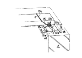
また、図20に示すように、壁面T1、U1が互いに交差してなる躯体T,U間の躯体間隙Vを壁面側から閉塞する躯体継手装置においては、躯体間隙短手方向に長尺な長孔111aと長尺でないボルト挿通孔111bを底面に設けてなるホルダー材111を躯体間隙Vを跨ぐように配設し、躯体Tの壁面T1から躯体間隙V内に張り出したボルト支持部材112にコイルバネ113付ボルト114を躯体間隙奥行き方向に伸縮可能に装着し、このボルト114のボルト頭114aを前記ホルダー材111の長孔111aに摺動自在に挿通係合する一方、躯体Uの壁面U1から躯体間隙V内に張り出したボルト支持部材115にボルト116を装着し、このボルト116のボルト頭116aを前記ホルダー材111の挿通孔111bに躯体間隙奥行き方向に伸縮自在に挿通係合し、躯体間隙短手方向に躯体が変動すると、長孔111a内をボルト114がスライドして躯体変動を吸収し、躯体間隙奥行き方向に躯体が変動すると、コイルバネ113の伸縮を伴ったボルト114の伸縮によって躯体変動を吸収し得るように構成してなる躯体継手装置110が知られていた。
【0005】
これら躯体継手装置100、110はいずれも、ホルダー材の底面に設ける長孔をより長く形成することで躯体間隙短手方向の変動に対する追随幅を大きくすることができる。しかし、この場合互いに離反する方向への変動追随幅を大きくするためには、ホルダー材を大型化し、かつ躯体壁面にホルダー材を重ねる幅も大きくとらなければならない。これではコスト的に効率が悪いばかりか、意匠性も低下するし、更にはホルダー材の大型化に対応してこれを支える支持部も強化しなければならないと言った問題が生じる。
また、躯体間隙奥行き方向の追随幅を大きくするためには、ボルト104、116の長さをより長くする必要があるが、躯体継手装置100、110は躯体間隙S、V内にボルト104、116が深く入り込む構造であるためボルト104、116の長さに比べて躯体の壁の厚さが充分大きくなければならない。つまり、どのような環境でもこの方向の追随幅を大きくできるものではなく、しかも、コイルバネ103、114は構造上バネ強度が経時的に低下し易いという問題もあった。
【0006】
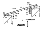
他方、片側固定タイプの躯体継手装置としては、図21に示すように、躯体間隙Sを跨ぐように配設してなるホルダー材121の基端側部を一方の躯体Qに対して回動可能に取付け、先端側は躯体壁面R1にフリーの状態で当接してなる構成の躯体継手装置120が知られていた。
【0007】
この躯体継手装置120は、ホルダー材121の先端側をフリーとすることによって、躯体間隙短手方向にも躯体間隙長手方向にも自在に変動することができる。また、躯体間隙奥行き方向に対してはホルダー材121の回動によって追随することができるから、躯体がいずれの方向に変動したとしてもこれに対応して追随することができる構成となっている。
しかし、この躯体継手装置120は、躯体間隙短手方向の大きな変動に追随できるようにするためには、ホルダー材121及びカバー材124をより大型化し、しかも躯体壁面R1に重ねる幅を大きくとらなければならず、上記の躯体継手装置100、110同様、効率、意匠性及び強度の点で問題が生じることとなる。
【0008】
そこで本発明は、かかる従来の課題を解決すべく、躯体間隙短手方向の追随幅、中でも離反方向に対する追随幅をより大きくすることができ、それでいて装置自体を大型化する必要のない一枚型躯体継手装置を提供せんとするものである。
【0009】
【課題を解決するための手段】
かかる課題を解決するため、本発明は、躯体間隙を介して隣接する躯体間を連結する一枚型躯体継手装置であって、躯体間隙を跨いで配設するホルダー材と、このホルダー材内に摺動自在に配設するスライド材と、ホルダー材の基端側を一方の躯体に回動自在に取付けると共にホルダー材を復元方向に付勢するホルダー材止め部と、スライド材の基端側を他方の躯体に回動自在に取付けると共にスライド材を復元方向に付勢するスライド材止め部と、ホルダー材を被覆し躯体間隙を被閉するカバー材とを備えてなる一枚型躯体継手装置を構成することとした。
【0010】
かかる構成を備えてなる躯体継手装置は、ホルダー材の一端をフリーとし、かつこのホルダー材内にスライド材を摺動自在に配設してあるから、隣接する躯体が躯体間隙短手方向に変動した場合、スライド材の摺動によってこの躯体変動を吸収することができる。しかもその際の追随幅は、離反方向に対してはホルダー材とスライド材とが重合している限り追随することができ、逆に近接方向に対してはホルダー材又はスライド材の先端部が躯体に当接して動かなくなるまで追随することができる。
また、ホルダー材及びスライド材の基端部側をそれぞれ一方の躯体に回動自在に取付け、かつ復元方向に付勢してあるから、躯体が躯体間隙奥行き方向に互いにずれるように繰り返し変動したとしても、この躯体変動に追随してこれを吸収することができる。
しかも、本発明の躯体継手装置は、通常状態では、ホルダー材内にスライド材が収納されるから、装置自体を大型化することなく大きな躯体変動を吸収することができ、しかもこの2重構造によって強度的にも優れたものとなっている。
さらにまた、ホルダー材及びスライド材の基端側を躯体に対して止めてあるから、複数の躯体継手装置を並設する場合であっても、各躯体継手装置の動作に整合性を与えることができ、隣接する躯体継手装置が衝突して破損することもない。
【0011】
上記構成において、「ホルダー材止め部」及び「スライド材止め部」は、躯体固定板に対し、軸部と軸受部とを介して弾性部材を回動可能に連設するように構成することができる。このような構成であれば、弾性部材を躯体に対して軸止し、この弾性部材を介してホルダー材又はスライド材を回動可能に止めることができる。
【0012】
その場合、弾性部材の軸部の長さをホルダー材止め部及びスライド材止め部の少なくとも一方の軸受部の長さよりも長く形成し、弾性部材を軸方向に可動可能とすることにより、躯体間隙長手方向の躯体変動にも追随することができる。
【0013】
また、弾性部材には、2つのねじりバネを線状部材で連結してなる構成を備えたものを使用するのが好ましい。弾性部材をこのような構造のバネに限定するものではないが、2つのねじりバネを備えているから、ねじりバネ一つのトーションバネや、コイルバネに比べてバネ強度が高く、経年使用によってバネ力が弱まりにくく、更には線状部材の変形によって躯体間隙長手方向への追随動作にも寄与することができる。
【0014】
なお、上記のホルダー材止め部及びスライド材止め部の構成において、回動自在とする手段はこのような構成に限定されるものではなく、ピンを軸としてホルダー材又はスライド材を軸止するように構成することも可能である。
【0015】
他方、上記ホルダー材止め部及びスライド材止め部の少なくとも一方は、躯体の躯体間隙長手方向に沿って配設したスライド受け部と、このスライド受け部内に摺動自在に配設し、弾性部材係止部を備えたスライド体と、弾性部材とから構成することもできる。このように構成すれば、ホルダー材又はスライド材を躯体間隙長手方向により大きく摺動可能とすることができる。躯体間隙長手方向の躯体変動に対しては、躯体継手装置を壁面間に設置する場合、この方向は垂直方向になる。大地震を想定してもその変動幅は僅かである。しかし、躯体継手装置を建物の天井面間に配設する場合は、この方向が水平に伸びる方向となるから大きな変動幅を想定する必要がある。したがって、上記の如くホルダー材又はスライド材を躯体間隙長手方向により大きく摺動可能とする構成は、建物の屋上間に配設する屋根型躯体継手装置の構成として特に有効である。
【0016】
また、上記の「ホルダー材」としては、例えば、カバー材当接面の他方を開口してなる断面略コ字状に形成し、このコ字状内には、長手方向に沿ってスライド嵌合部を設けるように構成することができる。これに対し、上記「スライド材」としては、スライド材本体の長手方向に壁部を連設し、この壁部に弾性部材を係合する弾性部材係止部を設けるように構成することができる。
【0017】
なお、本発明において、「躯体間隙短手方向」とは躯体が対面する方向を意味し、「躯体間隙奥行き方向」とは躯体継手装置のカバー材を正面に見た場合に躯体間隙の奥行きに前後する方向を意味する。「躯体間隙長手方向」とは躯体継手装置を配設する躯体間隙の縁に沿った方向、言い換えれば前記躯体間隙短手方向及び前記躯体間隙奥行き方向のいずれにも直交する方向を意味する。
【0018】
【発明の実施の形態】
以下、本発明の実施の形態を実施例に基づいて説明する。
【0019】
(実施例1)
躯体継手装置1は、図1及び図2に示すように、躯体間隙Cを介して隣接する躯体A,Bの壁面A1、B1間を連結する躯体継手装置であって、躯体間隙Cを跨いで配設したホルダー材2と、このホルダー材2内に摺動自在に配設したスライド材3と、ホルダー材2の基端側を躯体Aに回動自在に取付けると共にこのホルダー材2が回動した場合に復元方向に付勢するホルダー材止め部4と、スライド材3の基端側を躯体Bに回動自在に取付けると共にスライド材3を復元方向に付勢するスライド材止め部5と、ホルダー材2を被覆し躯体間隙Cを被閉するカバー材6とから構成してある。
【0020】
ホルダー材2は、図4〜図6に示すように、アルミニウムから形成してなる断面略C型材であり、長尺矩形状のカバー材当接面2aと、このカバー材当接面2aの両側縁から垂下してなる側面2b、2bと、この側面2b、2bの下端部から内側に折曲してなる鍔部2c、2cとから断面略C型を形成し、C型内部には、当該鍔部2c、2cと適宜間隔をおいて平行に鍔部2d、2dを設けて、これら鍔部2c、2c及び鍔部2d、2dからなる断面コ字状部が向き合った形状のスライド嵌合部7を設けている。この際、図5に示すように、カバー材当接面2aとスライド嵌合部7との間に空間部9を介在させ、カバー材当接面2aの外側からビス等の固定部材10を打ち込んでもその先端部がスライド材3に当たらないように設計してある。
また、カバー材当接面2aの躯体A側寄り部位には、図6に示すように、短手方向全幅に亘って係合溝8を設けてある。
【0021】
このホルダー材2は、上述のように、躯体間隙Cを跨いで壁面A1、B1間に架けて配設し、基端側のみ躯体に対してホルダー材止め部4で止め、先端側は躯体に対しては止めないでフリーの状態に取付けてある。
【0022】
ここで、ホルダー材止め部4は、図3に示すように、軸受部13を備えた躯体固定板14と、弾性部材15とから構成してある。
【0023】
躯体固定板14は、図3及び図6に示すように、矩形状の板体14aの一側縁に沿ってその両端に筒状の軸受部13、13を設け、板体14aの中央部にはホルダー材2を挟み得る間隔をおいて係止壁14b、14bを立設し、板体14a内にボルト等の固定部材16を打ち込んで壁面A1に重ねて固定してある。
【0024】
一方、弾性部材15は、金属製線材を折り曲げて形成してなるダブルトーションバネであり、2つのコイル状のねじりバネ15a、15aを備え、これらねじりバネ15a、15aの内側端部から延設してなる線状部材を矩形状に連結して掛止腕部15bを形成すると共に、ねじりバネ15a、15aの外側端部から固定腕部15c、15cを延設し、これら固定腕部15c、15cの端部を折曲して直線状の軸部15d、15dを形成すると共に、これら軸部15d、15dの端部を折曲して抜け止め部15e、15eを形成してある。ねじりバネ15aを2つ有するトーションバネであれば、バネ強度が高く大きな躯体変動にも負けることなくバネ力を発揮することができ、経年使用によってもバネ力が弱まりにくい。
【0025】
そして、この弾性部材15は、図6に示すように、その軸部15d、15dを上記躯体固定板14の軸受部13、13に介挿する一方、掛止腕部15bをホルダー材2の係合溝8に係合させて、図7(A)(B)に示すように、ホルダー材2の基端部側を躯体Aに対して回動自在に固定してある。この際、弾性部材15を介して回動可能に取付けることにより、例えば図7(A)に示すようにホルダー材2の先端側が外側に開く方向に回動した場合、ねじりバネ15a、15aの反発力が作用してホルダー材2を復元する方向に付勢するようになっている。
【0026】
スライド材3は、図4及び図5に示すように、上記ホルダー材2のスライド嵌合部7内に摺動自在に嵌合し得る長尺矩形板状のスライド材本体3aと、このスライド材本体3aの一側面の中央部において先端部から本体長手方向に沿って適宜長さに立設してなる壁部3bとを備えるように形成してあり、壁部3bの基端縁部には係合溝部17を設け、この壁部3bの側面にはねじりバネ21a、21aを係合装着できるようそれぞれ外側突出した弾性部材係止部18を設けてある。
スライド材3の長さは、特に限定するものではないが、ホルダー材2の約半分言い換えれば躯体間隙Cの短手幅の約半分とすることにより、遠近両方の躯体間隙短手方向の躯体変動に対してバランス良く吸収することができ、しかも充分な強度を確保することもできる。
【0027】
このスライド材3は、ホルダー材2のスライド嵌合部7内にスライド材本体3aを摺動自在に嵌挿させ(ホルダー材2の端部から突出可能)に装着し、スライド材止め部5を介してその基端側を躯体Bに回動自在に取付けてある。
【0028】
ここで、スライド材止め部5は、図3に示すように、軸受部19を備えた躯体固定板20と、弾性部材21とから構成してある。
【0029】
躯体固定板20は、矩形状の板体20aの一側縁に沿ってその両端に筒状の軸受部22、22を設け、板体20a内にボルト等の固定部材23を打ち込んで壁面B1に重ねて固定してある。
【0030】
弾性部材21は、金属製線材を折り曲げて形成してなるダブルトーションバネであり、2つのコイル状のねじりバネ21a、21aを備え、これらねじりバネ21a、21aの内側端部から延設してなる線部材をV字形状に連結して掛止腕部21bを形成すると共に、ねじりバネ21a、21aの外側端部から固定腕部21c、21cを延設し、これら固定腕部21c、21cの端部を折曲して直線状の軸部21d、21dを形成し、更にこれら軸部21d、21dの端部を折曲して抜け止め部21e、21eを形成してある。
【0031】
そしてこの弾性部材21の軸部21d、21dを上記躯体固定板20の軸受部22、22に介挿する一方、掛止腕部21bをスライド材3の係合溝部17に係合させてスライド材3の基端部側を躯体Bに対して回動自在に取付けてある。この際、弾性部材21を介してスライド材3を回動可能に取付けることにより、例えばスライド材3の先端側が外側に開く方向に回動した場合、ねじりバネ21a、21aの反発力が作用してスライド材3を復元する方向に付勢するようになっている。
【0032】
なお、スライド材止め部5においては、図8に示すように、軸受部19の長さを弾性部材21の軸部21dの長さよりも適宜短く形成し(図では2hだけ短く形成してある。)、軸部21dを軸方向に可動可能としてある。
【0033】
カバー材6は、躯体間隙Cの短手幅よりも長尺な短手幅と間隙Cに沿って長尺な長手幅を有する被覆面部6aの短手方向両側縁に沿って垂下して側面部6b、6bを形成し、これら側面部6b、6bの下端縁部下側にゴムなどの弾性部材からなるガスケット25.25を添設してある。
このカバー材6は、被覆面部6aをカバー材当接面2a上に重ね、この重合部にボルト等の固定部材を打ち込むなどして固定してある。
【0034】
次に、躯体継手装置1の動作について説明する。
【0035】
図9(B)(C)に示すように、躯体A,Bが互いに躯体間隙短手方向に変動した場合、ホルダー材2内をスライド材3が摺動してこの躯体変動を吸収することができる。
この際、図9(B)に示すように躯体A,Bが互いに近接する方向に変動する場合、スライド材3の壁部3b先端が躯体Aに当接するまで追随することができる。したがって、このスライド材3の壁部3b先端部(図の点線斜線部)を切除することで更にこの方向に対する追随幅を拡大することができる。
他方、図9(C)に示すように躯体A,Bが互いに離反する方向に変動する場合は、スライド材3がホルダー材2から抜き出てもホルダー材2とスライド材3とが重合している限り、正確にはホルダー材2のスライド嵌合部7内にスライド材3のスライド材本体3aが嵌合している限り躯体変動に追随することができる。つまり、スライド材3の長さだけ最大追随可能である。しかし、スライド材3の長さをあまり長くすると、躯体A,Bが近接方向に変動した場合の追随幅が狭くなってしまうから、好ましくはスライド材3の長さをホルダー材2の長さ或いは躯体間隙短手幅の約半分とし、遠近いずれの方向にも躯体間隙の半分程度は吸収することができるように設定する。その場合更に、上記の如くスライド材3の壁部3a先端部を切除すればより一層追随幅を拡大することができる。
【0036】
図10(A)(B)に示すように、躯体A,Bが互いに躯体間隙奥行き方向に変動した場合は、ホルダー材2及びスライド材3ともに弾性部材15又は21を介してその基端部側を躯体A,Bに回動自在に固定してあるから、躯体A,Bのいずれが外側に突出するように変動したとしても、特に制限なくこの躯体変動に追随して回動しこれを吸収することができる。しかも、ホルダー材2及びスライド材3ともに、弾性部材15又は21を介して復元方向に付勢されているから、躯体A,Bが躯体間隙奥行き方向に複雑に繰り返し変動したとしても、常に追随して変動することができる。
【0037】
また、図示はしないが、躯体A,Bが互いに躯体間隙長手(本例の場合は垂直方向)に変動した場合は、スライド材止め部5において、軸受部22内を弾性部材21の軸部21dが垂直方向に可動すると共に、弾性部材21の固定腕部21c、21cが変形することによってこの方向の躯体変動を吸収することができる。なお、大地震においても垂直方向の躯体変動幅は水平方向の変動幅に比べて僅かであるから、この程度追随できれば充分である。
さらに本実施例の場合、軸受け部内の軸部の可動によって躯体B側を軸受け躯体間隙方向に変動可能とする一方、躯体A側はホルダー材2を挟むように係止壁14b、14bを立設し、この方向に変動しないように構成してあるから、隣接する躯体連結装置1,1間におけるこの方向の追随動作に整合性を持たせることができ互いに衝突しないようになっている。
【0038】
(実施例2)
躯体継手装置31は、図11に示すように、躯体間隙Fを介して隣接する躯体D,Eの互いに交差する壁面D1、E1間を連結する躯体継手装置であって、図12に示すように、躯体間隙Fを跨いで配設したホルダー材32と、このホルダー材32内に摺動自在に配設したスライド材33と、ホルダー材32の基端側を躯体Dに回動自在に取付けると共にこのホルダー材32が回動した場合に復元方向に付勢するホルダー材止め部34と、スライド材33の基端側を躯体Eに回動自在に取付けると共にこのスライド材33が回動した場合に復元方向に付勢するスライド材止め部35と、ホルダー材32を被覆し躯体間隙Fを被閉するカバー材36とから構成してある。
【0039】
ホルダー材32は、上記のホルダー材2と同様、図12に示すように、アルミニウムから形成してなる断面略C型材であり、C型内部には、カバー材当接面32aとの間に空間部39を介在させるように開口縁部に添って断面コ字状部が向き合った如き形状のスライド嵌合部37を設けてある。なお、このホルダー材32には、上記ホルダー材2のように係合溝8は設けない。
【0040】
このホルダー材32は、上述のように、躯体間隙Fを跨いで壁面D1、E1間に架けて配設し、基端側のみ躯体に対してホルダー材止め部34で止め、先端側は躯体に対して止めないでフリーの状態としてある。
【0041】
ここで、ホルダー材止め部34は、図12〜図15に示すように、ホルダー材装着板体43と、躯体固定板体44と、弾性部材45とから構成してある。
【0042】
ホルダー材装着板体43は、図15に示すように、ホルダー材32の端部開口部に合致した矩形状板体43aの一側縁(図では下側縁)に沿ってその両端に筒状の軸受部43b、43bを設けると共に、これら板体43b、43bとは交差する方向の一側縁を垂直に折曲して上記ホルダー材32における空間部39及びスライド嵌合部37内にそれぞれ嵌入可能な片部を備えた突出片43c、43cを設けて形成してあり、これら突出片43c、43cをホルダー材32の躯体D側端開口部から嵌入し、ホルダー材32の側面においてボルト等の固定部材46を打ち込んでホルダー材32に固定してある。
【0043】
また、躯体固定板44は、図14に示すように、矩形状板体部44aの一側縁に沿ってその両端に筒状の軸受部44b、44bを設け、板体部44a内には、ホルダー材32を挟み得る間隔をおいて係止壁44c、44cを立設してあり、この躯体固定板44は、板体部44a内にボルト等の固定部材46を打ち込んで壁面D1に重ねて固定してある。
【0044】
また、弾性部材45は、上記弾性部材15と同様のダブルトーションバネであり、図14に示すように、2つのコイル状のねじりバネ45a、45a、矩形状の掛止腕部45b、固定腕部45c、45c、軸部45d、45d及び抜け止め部45e、45eを備え、各ねじりバネ45aを躯体固定板44の係止壁44cの外側に位置させ、軸部45d、45dを躯体固定板44の軸受部44b、44bに介挿してこの弾性部材45を躯体Dに対して回動自在に軸止する一方、掛止腕部45bをホルダー材32に固定したホルダー材装着板体43の軸受部43a、43a内に介挿し、ホルダー材32はその基端部側を躯体Dに対して回動自在とし、しかもねじりバネ45a、45aの反発力によってホルダー材32が回動した場合には復元させる方向に力を与えて付勢してある。
【0045】
スライド材33及びスライド材止め部35は、上記のスライド材3及びスライド材止め部5と同様に構成してある。
【0046】
カバー材36は、躯体間隙Fを被閉する被覆面部36aの短手方向一側端を垂直に折曲してホルダー材止め部34を被覆する交差被覆面部36bを形成し、被覆面部36a及び交差被覆面部36bの短手方向両端縁を垂下して側面部36c、36cを形成し、これら側面部36c、36cの下端縁部に沿ってゴムなどの弾性部材からなるガスケット25、25を添設してあり、被覆面部36aをカバー材当接面32a上に重ね、この重合部にボルト等の固定部材を打ち込むなどして固定してある。
【0047】
この躯体継手装置31も、上記躯体継手装置1同様、躯体D,Eが互いに躯体間隙短手方向に変動した場合、ホルダー材32内(突出も可能)をスライド材33が摺動することにより躯体変動を吸収することができ、この方向に対する追随幅も同様に拡大することができる。
また、躯体D,Eが互いに躯体間隙奥行き方向に変動した場合も躯体継手装置1同様、躯体D,Eのいずれが外側に突出するように変動したとしても、特に制限なくこれに追随して回動することができ、しかも、ホルダー材32及びスライド材33ともに、回動した場合には復元するように付勢されているから、躯体D,Eが躯体間隙奥行き方向に複雑に繰り返し変動したとしても、常にこれに追随動作してこの躯体変動を吸収することができる。
さらにまた、躯体D,Eが互いに躯体間隙長手(本例の場合は垂直方向)に変動した場合も、上記躯体継手装置1同様、スライド材止め部35における軸受部と弾性部材の軸部との可動と弾性部材の変形によってこの方向の躯体変動を吸収することができる。
【0048】
(実施例3)
躯体継手装置51は、図16及び図17に示すように、躯体間隙Cを介して隣接する躯体A,Bの天井面A2、B2間を連結する躯体継手装置であって、躯体間隙Cを跨いで配設したホルダー材52と、このホルダー材52内に摺動自在に配設したスライド材53と、ホルダー材52の基端側を躯体Aに回動自在に取付けると共にこのホルダー材52が回動した場合に復元方向に付勢するホルダー材止め部54と、スライド材53の基端側を躯体Bに回動自在に取付け、このスライド材53が回動した場合に復元方向に付勢すると共に躯体長手方向に摺動自在とするスライド材止め部55と、ホルダー材52を被覆し躯体間隙Cを被閉するカバー材56とから構成してある。
【0049】
すなわち、この躯体継手装置51は、ホルダー材52、スライド材53、ホルダー材止め部54(図示なし)、及びカバー材56については、上記躯体継手装置1と同様に構成し、これらを壁面A1及びB1に取付ける代わりに天井面A2及びB2に同様に取付け、一方、上記躯体継手装置1が、躯体固定板20と弾性部材21とからスライド材止め部5を構成し、躯体Bに固定した躯体固定板20に弾性部材21を軸止することによって弾性部材21を介してスライド材3を躯体Bに回動可能に取付けるのに対し、この躯体継手装置51は、図17に示すように、躯体Bの躯体間隙縁に沿って配設したスライド受け部61と、このスライド受け部61内に摺動自在に配設してなるスライド体62と、弾性部材63とからスライド材止め部55を構成し、スライド受け部61内に摺動自在に配設したスライド体62に弾性部材63を係止することによってこの弾性部材63を介してスライド材53を躯体間隙長手方向に摺動自在に取付けてある。
【0050】
ここで、スライド受け部61は、躯体Bの天井面B2に重ねて固着する固着面部61aの一側縁に沿って断面コ字状のスライドレール部61bを設けて形成してあり、固着面部61a内にボルトなどの固定部材を打ち込んで固着面部61aを天井面B2上に固定し、スライドレール部61bを躯体Bの躯体間隙縁に沿って間隙内に張り出すように配設してある。
【0051】
スライド体62は、上記スライド受け部61のスライドレール部61b内に嵌入可能な長尺矩形状のスライド板体部62aの一側面中央部にその長手方向に沿って固定鍔部62bを立設し、この固定鍔部62bの両端部に弾性部材係止孔62c、62cを設けて形成してあり、このスライド体62は、スライド板体部62aを上記スライド受け部61のスライドレール部61b内に摺動自在に嵌入してある。
【0052】
弾性部材63は、金属製線材を折り曲げて形成してなるダブルトーションバネであり、2つのコイル状のねじりバネ63a、63aを備え、これらねじりバネ63a、63aの内側端部から延設してなる線部材をV字形状に連結して掛止腕部63bを形成すると共に、ねじりバネ63a、63aの外側端部から固定腕部63c、63cを延設し、これら固定腕部63c、63cの端部を折曲して係止部63d、63dを設けて形成してある。
【0053】
そして、この弾性部材63の掛止腕部63bをスライド材53の係合溝部53aに係合させる一方、係止部63d、63dを上記スライド体62の弾性部材係止孔62cに係止させて、スライド体62とスライド材53とを連結し、スライド材53及びホルダー材52を躯体間隙長手方向に摺動自在としてある。
【0054】
このように構成することにより、躯体A,Bが互いに躯体間隙短手方向に変動した場合は、上記躯体継手装置1と同様にスライド材53がホルダー材52内をこの方向に摺動して躯体変動を吸収することができ、また、躯体A,Bが互いに躯体間隙長手方向に変動した場合は、スライド受け部61内を摺動するスライド体62を介してスライド材53及びホルダー材52をこの方向に摺動してこの躯体変動を吸収することができる。
さらにまた、躯体A,Bが互いに躯体間隙奥行き方向(本例の場合は垂直方向)に変動した場合、ホルダー材52及びスライド材53ともに、弾性部材を介して基端部側を躯体A,Bに回動自在としてあるから、躯体A,Bのいずれが上方に変動したとしてもこれに追随して回動することができる。しかも、ホルダー材52及びスライド材53ともに弾性部材を介して復元方向に付勢してあるから、躯体A,Bが躯体間隙奥行き方向に複雑に繰り返し変動したとしても、常に追随動作してこれを吸収することができる。
【0055】
(実施例4)
躯体継手装置71は、図18に示すように、躯体間隙Iを介して隣接する躯体G,Hの壁面G3、天井面H2間を連結する躯体継手装置であって、この躯体継手装置71は、上記躯体継手装置31同様、ホルダー材装着板体43、躯体固定板体44、及び弾性部材45からなるホルダー材止め部34によってホルダー材を躯体Gに対して回動自在とし、かつホルダー材を復元方向に付勢する一方、上記躯体継手装置51同様、スライド材止め部54によってスライド材53の基端側を躯体Hに回動自在に取付け、スライド材53を復元方向に付勢すると共に躯体長手方向に摺動自在となるように形成することができる。
【図面の簡単な説明】
【図1】本発明の一実施例としての躯体継手装置の一例の設置状態を示した一部断面斜視図である。
【図2】図1の躯体継手装置を上面から見た横断面図である。
【図3】図1の躯体継手装置におけるホルダー材止め部及びスライド材止め部の一例を示した正面図である。
【図4】図1の躯体継手装置のスライド材の基端側を躯体間隙内側から見た一部断面斜視図である。
【図5】図1の躯体継手装置の縦断面図である。
【図6】図1の躯体継手装置のホルダー材止め部の構成を示した斜視図である。
【図7】図6のホルダー材止め部及びホルダー材の動作を上面から見た場合の側面図である。
【図8】図1の躯体継手装置におけるスライド材止め部の構成例を示した正面図である。
【図9】図1の躯体継手装置の躯体間隙短手方向の動作を上面から見た場合の断面図であり、(A)は通常状態、(B)は躯体が近接方向に変動した場合、(C)は躯体が離反方向に変動した場合である。
【図10】(A)(B)ともに、図1の躯体継手装置の躯体間隙奥行き方向の動作を上面から見た場合の横断面図である。
【図11】本発明の他実施例としての躯体継手装置の一例の設置状態を示した一部断面斜視図である。
【図12】図11の躯体継手装置を上面から見た場合の側断面図である。
【図13】図12の躯体継手装置におけるホルダー材の基端側を上面側から見た場合の斜視図である。
【図14】図12の躯体継手装置におけるホルダー材止め部の一例を示した斜視図である。
【図15】図14のホルダー材止め部の構成部品としてのホルダー材装着板体の一例を示した斜視図である。
【図16】本発明の更なる他実施例としての躯体継手装置の一例の設置状態を示した斜視図である。
【図17】図16の躯体継手装置のホルダー材の取付け状態を躯体間隙内側(下側)から見た一部断面斜視図である。
【図18】本発明の更なる他実施例としての躯体継手装置の一例の設置状態を示した斜視図である。
【図19】従来の躯体継手装置の一例の躯体変動に伴う動作を上面から見た場合の横断面図である。
【図20】同じく、従来の躯体継手装置の一例の躯体変動に伴う動作を上面から見た場合の横断面図である。
【図21】同じく、従来の躯体継手装置の一例の躯体変動に伴う動作を上面から見た場合の横断面図である。
【符号の説明】
1 躯体継手装置
2 ホルダー材
2a カバー材当接面
3 スライド材
4 ホルダー材止め部
5 スライド材止め部
6 カバー材
7 スライド嵌合部
8 係合溝
9 空間部
13 軸受部
14 躯体固定板
15 弾性部材
17 係合溝部
18 弾性部材係止部
19 軸受部
20 躯体固定板
21 弾性部材
22 軸受部
31 躯体継手装置
32 ホルダー材
33 スライド材
34 ホルダー材止め部
35 スライド材止め部
36 カバー材
37 スライド嵌合部
39 空間部
43 ホルダー材装着板体
44 躯体固定板体
45 弾性部材
51 躯体継手装置
52 ホルダー材
53 スライド材
54 ホルダー材止め部
55 スライド材止め部
56 カバー材
61 スライド受け部
62 スライド体
63 弾性部材
71 躯体継手装置[0001]
BACKGROUND OF THE INVENTION
The present invention relates to a body joint device (expansion joint) that connects adjacent bodies via a body gap and can follow the body fluctuation caused by an earthquake or the like to absorb this body fluctuation, and in particular, a single cover. The present invention relates to a single-piece frame joint device for closing a frame gap with a material.
[0002]
[Prior art and problems to be solved by the invention]
In this type of frame joint device, that is, a single-layer type frame joint device that covers the frame gap with a single cover material, conventionally, both sides of the cover material that are movably fixed via a spring material or the like. There are two types, a fixed type and a one-side fixed type in which one of the cover materials is fixed movably with a spring material and the other is free.
[0003]
As shown in FIG. 19, for example, in the case of a body joint device that closes the gap S between the housings Q and R in which the wall surfaces are substantially flush with each other, as shown in FIG. A
[0004]
Further, as shown in FIG. 20, in the case joint apparatus for closing the case gap V between the cases T and U formed by intersecting the wall surfaces T1 and U1 from the wall surface side, the length is long in the short direction of the case gap. A
[0005]
In any of these frame
Further, in order to increase the following width in the frame gap depth direction, it is necessary to increase the length of the
[0006]
On the other hand, as shown in FIG. 21, as the one-side-fixed type housing joint device, the base end side portion of the
[0007]
The frame joint device 120 can be freely changed in both the width direction of the frame gap and the lengthwise direction of the frame gap by making the front end side of the
However, in order that the frame joint device 120 can follow a large variation in the width direction of the frame gap, the
[0008]
Therefore, in order to solve such a conventional problem, the present invention can increase the following width in the lateral direction of the gap between the casings, in particular, the following width in the separation direction, and yet does not need to increase the size of the apparatus itself. It is intended to provide a frame joint device.
[0009]
[Means for Solving the Problems]
In order to solve such a problem, the present invention provides a single-piece frame joint device for connecting adjacent frames via a frame gap, a holder material disposed across the frame gap, and the holder material A slide material that is slidably disposed, a holder material stopper that urges the holder material in a restoring direction while rotatably attaching the proximal end side of the holder material to one housing, and a proximal end side of the slide material A one-piece frame joint device comprising: a slide material stopper that rotatably attaches to the other housing and urges the slide material in a restoring direction; and a cover material that covers the holder material and covers the housing gap. It was decided to compose.
[0010]
In the frame joint device having such a configuration, since one end of the holder material is free and the slide material is slidably disposed in the holder material, the adjacent frames vary in the short direction of the gap between the frames. In such a case, the change in the housing can be absorbed by the sliding of the slide material. In addition, the follow width at that time can follow the separation direction as long as the holder material and the slide material are superposed, and conversely, the tip of the holder material or the slide material is the housing in the proximity direction. It is possible to follow until it stops touching.
In addition, since the base end side of the holder material and the slide material are each rotatably attached to one housing and biased in the restoring direction, it is assumed that the housing repeatedly fluctuates so as to deviate from each other in the housing gap depth direction. However, it is possible to absorb this following the body fluctuation.
Moreover, in the normal state, the housing joint device of the present invention accommodates large housing fluctuations without increasing the size of the device itself because the slide material is accommodated in the holder material. It is also excellent in strength.
Furthermore, since the base end sides of the holder material and the slide material are fixed to the housing, even when a plurality of housing joint devices are arranged in parallel, it is possible to provide consistency to the operation of each housing joint device. The adjacent housing joint device does not collide and break.
[0011]
In the above configuration, the “holder material stopper” and the “slide material stopper” An elastic member is rotatably connected to the frame fixing plate via the shaft portion and the bearing portion. Can be configured. If it is such a structure, an elastic member can be axially fixed with respect to a housing, and a holder material or a slide material can be stopped rotatably via this elastic member.
[0012]
In that case, The length of the shaft part of the elastic member Holder material stopper and Slide material stopper By forming the elastic member longer than the length of at least one of the bearing portions and making the elastic member movable in the axial direction, it is possible to follow the fluctuation of the casing in the longitudinal direction of the casing gap.
[0013]
In addition, it is preferable to use an elastic member having a configuration in which two torsion springs are connected by a linear member. Although the elastic member is not limited to a spring having such a structure, since it has two torsion springs, the spring strength is higher than that of a torsion spring with one torsion spring or a coil spring. It is difficult to weaken, and it can also contribute to the follow-up operation in the longitudinal direction of the housing gap by the deformation of the linear member.
[0014]
In the configuration of the holder material stopper and the slide material stopper described above, the means for allowing rotation is not limited to such a configuration, and the holder material or the slide material may be fixed with the pin as an axis. It is also possible to configure.
[0015]
On the other hand, the holder material stopper and the slide material stopper At least one of Is Rod A slide receiving portion disposed along the longitudinal direction of the housing gap, a slide body that is slidably disposed in the slide receiving portion and includes an elastic member locking portion, and an elastic member may be used. If comprised in this way, a holder material or a slide material can be largely slidable to a housing gap | interval longitudinal direction. With respect to the case fluctuation in the longitudinal direction of the case gap, when the case joint apparatus is installed between the wall surfaces, this direction becomes the vertical direction. Even if a large earthquake is assumed, the fluctuation range is slight. However, when the frame joint device is disposed between the ceiling surfaces of the building, it is necessary to assume a large fluctuation range because this direction is a direction extending horizontally. Therefore, the configuration in which the holder material or the slide material can be largely slid in the longitudinal direction of the housing gap as described above is particularly effective as the configuration of the roof-type housing joint device disposed between the roofs of the buildings.
[0016]
In addition, as the above-mentioned “holder material”, for example, the other side of the cover material contact surface is formed in an approximately U-shaped cross section, and the U-shaped slide fits along the longitudinal direction. It can comprise so that a part may be provided. On the other hand, as the “slide material”, a wall portion is continuously provided in the longitudinal direction of the slide material body, and an elastic member is engaged with the wall portion. Elastic member locking part It can comprise so that it may provide.
[0017]
In the present invention, the “body gap short direction” means the direction in which the chassis faces, and the “frame gap depth direction” means the depth of the chassis gap when the cover material of the chassis joint device is viewed from the front. It means the direction to go back and forth. The “frame gap longitudinal direction” means a direction along the edge of the frame gap in which the frame joint device is disposed, in other words, a direction orthogonal to both the width direction of the frame gap and the depth direction of the frame gap.
[0018]
DETAILED DESCRIPTION OF THE INVENTION
Hereinafter, embodiments of the present invention will be described based on examples.
[0019]
Example 1
As shown in FIGS. 1 and 2, the frame
[0020]
As shown in FIGS. 4 to 6, the
Further, as shown in FIG. 6, an engagement groove 8 is provided over the entire width in the lateral direction at a portion of the cover
[0021]
As described above, the
[0022]
Here, as shown in FIG. 3, the
[0023]
As shown in FIGS. 3 and 6, the
[0024]
On the other hand, the
[0025]
As shown in FIG. 6, the
[0026]
As shown in FIGS. 4 and 5, the
The length of the
[0027]
The
[0028]
Here, as shown in FIG. 3, the
[0029]
The
[0030]
The
[0031]
The
[0032]
In addition, in the
[0033]
The
The
[0034]
Next, the operation of the housing
[0035]
As shown in FIGS. 9B and 9C, when the casings A and B change in the shorter direction of the gap between the casings, the
At this time, as shown in FIG. 9B, when the casings A and B change in the direction in which they approach each other, it is possible to follow until the tip of the
On the other hand, as shown in FIG. 9C, when the casings A and B fluctuate in a direction away from each other, the
[0036]
As shown in FIGS. 10 (A) and 10 (B), when the housings A and B change in the housing gap depth direction, both the
[0037]
Although not shown in the figure, when the casings A and B change in the length of the gap between the casings (vertical direction in this example), the
Further, in the case of this embodiment, the housing B side can be changed in the bearing housing gap direction by the movement of the shaft portion in the bearing portion, while the housing A side is provided with the locking
[0038]
(Example 2)
As shown in FIG. 11, the frame
[0039]
As shown in FIG. 12, the
[0040]
As described above, the
[0041]
Here, as shown in FIGS. 12 to 15, the holder material stopper 34 includes a holder
[0042]
As shown in FIG. 15, the holder
[0043]
Further, as shown in FIG. 14, the housing fixing plate 44 is provided with cylindrical bearing
[0044]
Further, the elastic member 45 is a double torsion spring similar to the
[0045]
The
[0046]
The
[0047]
Similarly to the above-described frame
Further, even when the housings D and E change in the depth direction of the housing gap, even if any of the housings D and E changes so as to protrude outward, as with the housing
Furthermore, even when the housings D and E change in the longitudinal direction of the housing gap (in the vertical direction in this example), as in the case of the housing
[0048]
(Example 3)
As shown in FIGS. 16 and 17, the frame
[0049]
That is, this frame
[0050]
Here, the
[0051]
The slide body 62 is provided with a fixed
[0052]
The
[0053]
Then, the latching arm portion 63b of the
[0054]
With this configuration, when the casings A and B change in the lateral direction of the casing gap, the
Furthermore, when the housings A and B change in the housing gap depth direction (in this example, the vertical direction), both the
[0055]
Example 4
As shown in FIG. 18, the frame
[Brief description of the drawings]
FIG. 1 is a partial cross-sectional perspective view showing an installation state of an example of a housing joint device as an embodiment of the present invention.
FIG. 2 is a cross-sectional view of the housing joint device of FIG. 1 as viewed from above.
3 is a front view showing an example of a holder material stopper and a slide material stopper in the case joint apparatus of FIG. 1. FIG.
4 is a partial cross-sectional perspective view of the base end side of the slide member of the housing joint device of FIG. 1 as viewed from the inside of the housing gap.
FIG. 5 is a longitudinal sectional view of the housing joint device of FIG. 1;
6 is a perspective view showing a configuration of a holder material stopper of the housing joint device of FIG. 1. FIG.
7 is a side view when the operation of the holder material stopper and the holder material of FIG. 6 is viewed from above. FIG.
8 is a front view showing a configuration example of a slide material stopper in the housing joint device of FIG. 1. FIG.
9 is a cross-sectional view of the operation of the housing joint device of FIG. 1 in the housing gap short direction when viewed from above, (A) is a normal state, (B) is a case where the housing is changed in the proximity direction, (C) is a case where a housing | casing fluctuates in the separation direction.
10 (A) and 10 (B) are cross-sectional views when the operation in the frame gap depth direction of the frame joint device of FIG. 1 is viewed from above.
FIG. 11 is a partial cross-sectional perspective view showing an installation state of an example of a frame joint device as another embodiment of the present invention.
12 is a side sectional view of the housing joint device of FIG. 11 as viewed from above.
13 is a perspective view when the base end side of the holder material in the case joint apparatus of FIG. 12 is viewed from the upper surface side.
14 is a perspective view showing an example of a holder material stopper in the housing joint apparatus of FIG. 12. FIG.
15 is a perspective view showing an example of a holder material mounting plate as a component of the holder material stopper in FIG.
FIG. 16 is a perspective view showing an installation state of an example of a housing joint device as still another embodiment of the present invention.
17 is a partial cross-sectional perspective view of the attachment state of the holder material of the housing joint device of FIG. 16 as viewed from the inside (lower side) of the housing gap.
FIG. 18 is a perspective view showing an installation state of an example of a housing joint device as still another embodiment of the present invention.
FIG. 19 is a cross-sectional view of an example of a conventional case joint apparatus as viewed from the top with respect to an operation associated with case change.
FIG. 20 is a cross-sectional view of the operation associated with the variation of the casing of the example of the conventional casing joint device as viewed from above.
FIG. 21 is a cross-sectional view of an example of a conventional case joint apparatus as seen from the top in connection with the case change.
[Explanation of symbols]
1 Body joint device
2 Holder material
2a Cover material contact surface
3 Slide material
4 Holder material stopper
5 Slide material stopper
6 Cover material
7 Slide fitting part
8 engaging groove
9 Space
13 Bearing part
14 Housing fixing plate
15 Elastic member
17 engaging groove
18 Elastic member locking part
19 Bearing part
20 Housing fixing plate
21 Elastic member
22 Bearing part
31 Housing joint device
32 Holder material
33 Slide material
34 Holder material stopper
35 Slide material stopper
36 Cover material
37 Slide fitting part
39 Space
43 Holder material mounting plate
44 Body fixing plate
45 Elastic member
51 Body joint device
52 Holder material
53 Slide material
54 Holder material stopper
55 Slide material stopper
56 Cover material
61 Slide receiver
62 Slide body
63 Elastic member
71 Body joint device
Claims (4)
Priority Applications (1)
| Application Number | Priority Date | Filing Date | Title |
|---|---|---|---|
| JP2000232047A JP3898424B2 (en) | 2000-07-31 | 2000-07-31 | Single piece frame joint device |
Applications Claiming Priority (1)
| Application Number | Priority Date | Filing Date | Title |
|---|---|---|---|
| JP2000232047A JP3898424B2 (en) | 2000-07-31 | 2000-07-31 | Single piece frame joint device |
Publications (3)
| Publication Number | Publication Date |
|---|---|
| JP2002047739A JP2002047739A (en) | 2002-02-15 |
| JP2002047739A5 JP2002047739A5 (en) | 2006-08-03 |
| JP3898424B2 true JP3898424B2 (en) | 2007-03-28 |
Family
ID=18724786
Family Applications (1)
| Application Number | Title | Priority Date | Filing Date |
|---|---|---|---|
| JP2000232047A Expired - Fee Related JP3898424B2 (en) | 2000-07-31 | 2000-07-31 | Single piece frame joint device |
Country Status (1)
| Country | Link |
|---|---|
| JP (1) | JP3898424B2 (en) |
Families Citing this family (3)
| Publication number | Priority date | Publication date | Assignee | Title |
|---|---|---|---|---|
| JP4913999B2 (en) * | 2004-09-30 | 2012-04-11 | 株式会社日本アルミ | Expansion joint device |
| JP5771080B2 (en) * | 2011-07-01 | 2015-08-26 | 株式会社ナルコ岩井 | Wall expansion joint device |
| JP6261419B2 (en) * | 2014-03-28 | 2018-01-17 | 理研軽金属工業株式会社 | Expansion joint structure |
-
2000
- 2000-07-31 JP JP2000232047A patent/JP3898424B2/en not_active Expired - Fee Related
Also Published As
| Publication number | Publication date |
|---|---|
| JP2002047739A (en) | 2002-02-15 |
Similar Documents
| Publication | Publication Date | Title |
|---|---|---|
| KR101456898B1 (en) | Folding door | |
| JP3898424B2 (en) | Single piece frame joint device | |
| JP5102405B1 (en) | Wall cover material support device and wall expansion joint | |
| JP4135938B2 (en) | Expansion joint | |
| JP3691131B2 (en) | Expansion joint | |
| JP3618692B2 (en) | Expansion joint end structure | |
| KR20210092559A (en) | Non exposed curtain wall system | |
| WO2020124378A1 (en) | Hinge device, shell, and electronic device | |
| JP3204945B2 (en) | Wall panel equipment | |
| US20180066468A1 (en) | Anti-rattle elements for internal divider of glass assembly | |
| JP2741578B2 (en) | Sash | |
| JP3979969B2 (en) | Expansion joint | |
| JP2912209B2 (en) | Expansion joint | |
| JP3089617B2 (en) | Upper runner | |
| JP4755021B2 (en) | Setback opening device | |
| JP2006219907A (en) | Wind breaker panel | |
| JP5351395B2 (en) | Revolving door device | |
| KR200229472Y1 (en) | An apparatus for coupling of bracket of roll screen | |
| JP3858099B2 (en) | Expansion joint | |
| JP2000265576A (en) | Building frame joint device | |
| JP3204482B2 (en) | Expansion joint | |
| JPH09111894A (en) | Expansion joint | |
| JP3116002B2 (en) | Wall covering device | |
| JP2599040Y2 (en) | Roll screen | |
| JP2542556B2 (en) | Tumbling window |
Legal Events
| Date | Code | Title | Description |
|---|---|---|---|
| A521 | Written amendment |
Free format text: JAPANESE INTERMEDIATE CODE: A523 Effective date: 20060620 |
|
| A621 | Written request for application examination |
Free format text: JAPANESE INTERMEDIATE CODE: A621 Effective date: 20060620 |
|
| A871 | Explanation of circumstances concerning accelerated examination |
Free format text: JAPANESE INTERMEDIATE CODE: A871 Effective date: 20060620 |
|
| A975 | Report on accelerated examination |
Free format text: JAPANESE INTERMEDIATE CODE: A971005 Effective date: 20060710 |
|
| A131 | Notification of reasons for refusal |
Free format text: JAPANESE INTERMEDIATE CODE: A131 Effective date: 20060718 |
|
| A521 | Written amendment |
Free format text: JAPANESE INTERMEDIATE CODE: A523 Effective date: 20060907 |
|
| TRDD | Decision of grant or rejection written | ||
| A01 | Written decision to grant a patent or to grant a registration (utility model) |
Free format text: JAPANESE INTERMEDIATE CODE: A01 Effective date: 20061121 |
|
| A61 | First payment of annual fees (during grant procedure) |
Free format text: JAPANESE INTERMEDIATE CODE: A61 Effective date: 20061221 |
|
| R150 | Certificate of patent or registration of utility model |
Ref document number: 3898424 Country of ref document: JP Free format text: JAPANESE INTERMEDIATE CODE: R150 Free format text: JAPANESE INTERMEDIATE CODE: R150 |
|
| FPAY | Renewal fee payment (event date is renewal date of database) |
Free format text: PAYMENT UNTIL: 20110105 Year of fee payment: 4 |
|
| R250 | Receipt of annual fees |
Free format text: JAPANESE INTERMEDIATE CODE: R250 |
|
| FPAY | Renewal fee payment (event date is renewal date of database) |
Free format text: PAYMENT UNTIL: 20120105 Year of fee payment: 5 |
|
| R250 | Receipt of annual fees |
Free format text: JAPANESE INTERMEDIATE CODE: R250 |
|
| FPAY | Renewal fee payment (event date is renewal date of database) |
Free format text: PAYMENT UNTIL: 20130105 Year of fee payment: 6 |
|
| R250 | Receipt of annual fees |
Free format text: JAPANESE INTERMEDIATE CODE: R250 |
|
| R250 | Receipt of annual fees |
Free format text: JAPANESE INTERMEDIATE CODE: R250 |
|
| R250 | Receipt of annual fees |
Free format text: JAPANESE INTERMEDIATE CODE: R250 |
|
| R250 | Receipt of annual fees |
Free format text: JAPANESE INTERMEDIATE CODE: R250 |
|
| R250 | Receipt of annual fees |
Free format text: JAPANESE INTERMEDIATE CODE: R250 |
|
| R250 | Receipt of annual fees |
Free format text: JAPANESE INTERMEDIATE CODE: R250 |
|
| R250 | Receipt of annual fees |
Free format text: JAPANESE INTERMEDIATE CODE: R250 |
|
| R250 | Receipt of annual fees |
Free format text: JAPANESE INTERMEDIATE CODE: R250 |
|
| LAPS | Cancellation because of no payment of annual fees |