JP3893174B2 - Interactive desktop system - Google Patents
Interactive desktop system Download PDFInfo
- Publication number
- JP3893174B2 JP3893174B2 JP27057096A JP27057096A JP3893174B2 JP 3893174 B2 JP3893174 B2 JP 3893174B2 JP 27057096 A JP27057096 A JP 27057096A JP 27057096 A JP27057096 A JP 27057096A JP 3893174 B2 JP3893174 B2 JP 3893174B2
- Authority
- JP
- Japan
- Prior art keywords
- bar
- camera
- area
- display
- image
- Prior art date
- Legal status (The legal status is an assumption and is not a legal conclusion. Google has not performed a legal analysis and makes no representation as to the accuracy of the status listed.)
- Expired - Fee Related
Links
Images


Classifications
-
- G—PHYSICS
- G06—COMPUTING; CALCULATING OR COUNTING
- G06K—GRAPHICAL DATA READING; PRESENTATION OF DATA; RECORD CARRIERS; HANDLING RECORD CARRIERS
- G06K7/00—Methods or arrangements for sensing record carriers, e.g. for reading patterns
- G06K7/10—Methods or arrangements for sensing record carriers, e.g. for reading patterns by electromagnetic radiation, e.g. optical sensing; by corpuscular radiation
- G06K7/14—Methods or arrangements for sensing record carriers, e.g. for reading patterns by electromagnetic radiation, e.g. optical sensing; by corpuscular radiation using light without selection of wavelength, e.g. sensing reflected white light
- G06K7/1404—Methods for optical code recognition
- G06K7/1408—Methods for optical code recognition the method being specifically adapted for the type of code
- G06K7/143—Glyph-codes
-
- G—PHYSICS
- G06—COMPUTING; CALCULATING OR COUNTING
- G06F—ELECTRIC DIGITAL DATA PROCESSING
- G06F3/00—Input arrangements for transferring data to be processed into a form capable of being handled by the computer; Output arrangements for transferring data from processing unit to output unit, e.g. interface arrangements
- G06F3/01—Input arrangements or combined input and output arrangements for interaction between user and computer
- G06F3/03—Arrangements for converting the position or the displacement of a member into a coded form
- G06F3/033—Pointing devices displaced or positioned by the user, e.g. mice, trackballs, pens or joysticks; Accessories therefor
-
- G—PHYSICS
- G06—COMPUTING; CALCULATING OR COUNTING
- G06T—IMAGE DATA PROCESSING OR GENERATION, IN GENERAL
- G06T7/00—Image analysis
- G06T7/80—Analysis of captured images to determine intrinsic or extrinsic camera parameters, i.e. camera calibration
Description
【0001】
【産業上の利用分野】
本発明は、カメラ・プロジェクタ構造を介してユーザが対話式にドキュメントを操作するドキュメント処理システム、特に、投影表示でカメラの視界の校正を行うことに関する。
【0002】
【従来の技術】
デスク情報に設置したカメラ・プロジェクタ構造を用いてユーザがカメラの視界内に位置するアイテムを選択することによって実施しようとしている機能を選択できるようにすることは、ヨーロッパ特許出願公開第495,622号から公知である。デスク上の書類の画像をキャプチャするのにはビデオ・カメラあるいはスキャナが用いられ、フィードバック情報が投影表示によって表示される。機能としては、デスク上に置かれたデータ(たとえば、紙の書類のデータ)について実施される計算、翻訳の操作がある。このようなシステムでは、カメラと表示が合致した状態に保持されてなければならず、カメラの視界が表示に関して変化したときにはいつでも校正を行わなければならない。
【0003】
たとえば、ユーザが或る書類の1つの単語を選んだとき、フィードバックを表示してその選択が単語と正確に一致しているかを確認しなければならない。表示座標系に対するカメラの視界のサイズ、向きおよび位置が知られていれば、表示された情報の位置を計算できる。
【0004】
この校正上の問題を解決する提案が種々なされているが、そこでは作業面に校正マークを投影している。ヨーロッパ特許出願公開第622,722号が開示している校正システムは、太い十字印すなわち「プラス」記号(+)を投影し、画像形態(Image Morphology)法(D. Bloomberg & P. Maragos, "Image Algebra and Morphological Image Processing", SPIE Conference Procs. San Diego, CA., July 1990 参照)を用いてフレーム・グラバ座標スペースにおいてマークの中心をピンポイントする。十字(+)は4つの連続した点に投影され、これら4つの点からマッピングを計算するために、これらの技術では、以下の式を使用する(ヨーロッパ特許出願公開第622,722号の第4図を参照)。
【0005】
x'=c1x+c2y+c3xy+c4
y'=c5x+c6y+c7xy+c8
ここで、(x、y)は投影表示における座標であり、(x′、y′)はフレーム・グラバにおける座標である。4つの点の対の場合、この連立一次方程式の解はガウス消去で得られる。次に、5番目の十字(+)を投影し、その位置をチェックしてマッピングによって生じた位置に充分に近いことを確認する。このプロセスはカメラが表示に一致していないことによって生じたキーストーニング(keystoning)効果、回転効果を処理し、結果は1つまたは2つの表示画素内にあるが、ユーザがカメラの視界のおおまかな位置を手作業で指定しなければならず、したがって、視界が常にまたは頻繁に変わる状況では不適切である。
【0006】
したがって、視界が変化しても迅速かつ自動的に実行できる校正技術が必要である。また、作業面が散らかっていて複数の書類がカメラの視界内に位置しているときでも有効である校正技術が必要である。そして、広い範囲の視界をうまく処理できる校正技術も必要である。
【0007】
本発明は、作業面と、この作業面上の第1領域に画像を表示する手段と、作業面上の第2領域の画像をキャプチャする手段と、表示手段およびキャプチャ手段に接続してあるプロセッサ手段とから成り、このプロセッサ手段が、(a)作業面上にコード化された情報を表示させ、(b)前記コード化情報のキャプチャを行わせ、(c)前記キャプチャされたコード化情報に応じて前記第1領域に対する前記第2領域の位置を決定する手段を包含することを特徴とする対話式デスクトップ・システムを提供する。
【0008】
好ましくは、表示手段はプロジェクタで成り、キャプチャ手段はカメラから成る。
【0009】
本発明の1つの利点は、ユーザがカメラの視界の下で校正表示を位置決めするのにユーザの手出しが不要であるということにある。すなわち、視界がアプリケーションで調節されるときに校正が自動的に行われる。
【0010】
別の利点は、3つの連続した画像フレームの表示、グラビング(grabbing:つかみ取り) だけが必要であるということにある。それに対して、従来技術では、5つ(4つの角隅表示と最終的な精度チェック)を必要とする。本発明の技術はより迅速である。
【0011】
また別の利点は、作業面が書類で覆われている場合でも迅速に作業を行えることにある。これにより、ユーザが校正中にデスクを整頓する必要がなくなり、ここでもペーパー作業を進めながら自動的に(および周期的に)校正することが可能となるである。
【0012】
【発明の実施の形態】
以下、本発明の実施例を添付図面を参照しながら説明する。
【0013】
A.基本システム
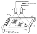
作業面112上方に設置され、そこに合焦されるビデオ・カメラ116、プロジェクタ118を用いる、本発明による全体的なシステム構成が図1に示してある。このシステム101は、1996年7月12日出願の英国特許出願第9614837.4号に記載されている形態のうち任意の形態を採用し得る。
【0014】
作業面すなわち平坦なデスク面(トップ)112には、ヨーロッパ特許出願公開第622,722号に記載されているように、テキスト情報あるいはグラフィック情報のソースとして使用しようとしている書類114が置いてある。この書類114はデスク面112上方に装置したビデオ・カメラ116の視界内に置かれている。カメラ116に隣接してプロジェクタ118が装置してあり、これはデスク面112上に表示121を投影する。この表示は、全体的にカメラ116の視界とほぼ一致しており、図示実施例では、新しく作り出されたドキュメントの画像120を含んでいる。カメラ116およびプロジェクタ118は、共に、画像処理システム(図示せず)に接続してあり、この画像処理システムは、たとえば、標準のマイクロコンピュータ(PC)を有するコンピュータであってもよい。これは図2を参照しながらより詳しく説明する。
【0015】
当業者には明らかであるように、本発明は Windows(登録商標)の作動するコンピュータを使用することを意図しており、フレーム・グラバ・ボードおよび適切なインタフェース回路を備えていてもよい(たとえば、Jahne B., Digital Image Processing, Appendix B, Springer-Verlag, Heidelberg, 1991 参照)。
【0016】
あるいは、ヨーロッパ特許出願公開第622,722号に詳細に記載されているハードウェア構造を用いてもよい。
【0017】
本発明を実施する際に、ヨーロッパ特許出願公開第622,722号に記載されている画像処理装置を用い、適当にあるいは以下に説明するようにまたはこれら両方の要領で改造してもよい。
【0018】
コンピュータは、ネットワーク・ケーブルに接続してある。このケーブルは、普通の内部ドライバ・カード(図示せず)および適当なソフトウェア(たとえば、Novell Corp.の市販しているNetware )と共に、この技術分野では周知のように、コンピュータでローカル・ネットワーク(LAN)あるいはワイド・エリア・ネットワーク(WAN)の一部を形成することができる。
【0019】
本発明の1つの好ましい実施例で用いた画像処理コンピュータのハードウェアが図2に概略的に示してある。この構造は、当業者にとって周知であり、たとえば、The Art of Electronics, Second Edition, Ch.10, P. Horowitz and W. Hill, Cambridge University Press, 1989に詳細に記載されている。簡単に言えば、このシステムは、共通バス130に接続した中央処理装置32、ランダムアクセスメモリ(RAM)34及びリードオンリーメモリ(ROM)36を包含するメモリ装置、ディスクドライブやテープドライブやCD−ROMドライブ等の記憶装置38、キーボード12、マウス14、プリンタやプロットやスキャナ等の装置40、A/D変換及びD/A変換装置42、およびカメラ116、ビデオ・プロジェクタ118、LANの残部(図示せず)のような外部装置46にインタフェースするディジタル入出力装置44を包含する。
【0020】
B.自動校正
本発明の1つの好ましい実施例によれば、カメラの視界の位置は、それが表示によって覆われている領域内に位置しているときにはいつでも自動的に決定される。これは、或る形態のバーコードを表示し、カメラを介してこれらバーコードの画像をつかみ取ることによって行われる。バーコードのつかみ取られた画像を解析してカメラがどこを見ていることを決定する。3つの連続した画像(ブランク表示と2組のバーコード)を表示してつかみ取り、解析を行うときには、デスクが整頓されているか書類で散らかっているかどうかには関係なく、ユーザの介入なしに、カメラおよび投影表示を校正できる。表示されたバーコードは商品にラベル付けするのに用いられるバーコードとは異なる設計である。
【0021】
図3は、本発明の一実施例で用いられるバーコード1を示しており、このバーコードは、デスク面(デスクトップ)に投影されたバー204及び206:210及び212、216及び218、222及び224の4つのグループ202、208、214、220からなる。これらのバーは、異なった太さ、たとえば、1画素幅と2画素幅で形成してもよい。1グループの始点にあるバー(たとえば204)から次のグループの開始点のバー(たとえば、210)までの距離は一定であり、バーコード1のピッチと呼ぶ。ピッチの割合として表されている、或るグループの最初のバーから最後のバーまでの距離は、バー・グループの広がりと呼ぶ。この実施例では、広がりはグループ毎に異なっていてもよいが、常に1ピッチの0.5未満である。これにより、各グループの開始点を検出できる。
【0022】
この技術によれば、一連のバー・グループが使用され、広がりは認識可能なシーケンスで変化する。カメラは表示された画像の一部をつかみ取り、バーに対して直角な1つの走査線(以下の図5及びその説明を参照)に沿った画素値が調べられる。バーが前記の走査線に見つけられる場合、これらのバーがグループとして形成されることができ、そのグループの広がりは、表示されたパターンの広がりに一致させることができる。
【0023】
図4に目を転じて、この図は走査線に沿った画素値のプロットすなわちグラフを示しており、これは複雑なバックグラウンド上にバーを表示する効果を示している。ブランクフレームが投影されてつかみ取られた後、まず、バーコード1が表示を左から右に(矢印Aの方向に)横切るように延びた状態で、1つのバーコード・フレームが投影される。そのバーコード1の各バーは表示の高さ一杯にわたっていて、表示のほぼ全体がバーコード1で満たされる。このバーコードが投影されている間に、そのバーコード・フレームがカメラによってつかみ取られる(キャプチャされる)。次に、このステップは、直交する向き(各バーが水平になり且つバーコードが表示の幅方向に広がる向き)wにおいて、1つの投影されたバーコードについて、繰り返される。1組で3つの表示とグラブ(grab:つかみ取り=キャプチャ )を用いることによって、デスク上に位置する書類の干渉効果は大きく除去できる。第2及び第3のグラブ(垂直バー及び水平バー)からの画素値は、第1のグラブ(ブランク表示)の値から減算され、各バーそのものから生じた1組の画素値の差の値を形成する。図4において、曲線26は、ブランク表示でつかみ取られた画像についての走査線に沿った画素値対位置のグラフを示しており、曲線28は、表示したバーコードでつかみ取られた画像についての走査線に沿った画素値対位置のグラフを示し、曲線30は前記の画素値差を示しており、ここでは、2つの主要ピークが1グループ内の2つの太いバーの位置を示している。
【0024】
曲線26〜30はサンプリングの平滑化効果を示している。曲線30は、好ましくは、最高値の半分の値でスレッショルド処理され、これによって、外側のピーク29a、29bが、太いバー23a、23bに対応する2つの外側の幅広の方形波パルス21a、21bを発生し、内側のピーク31a、31bが、太いバー25a、25bに対応する2つの内側の幅狭い方形波パルス19a、19bを発生する。
【0025】
図5の(a)は、一連のグループ202、208、214、220、221からなる表示バーコードを示しており、その内の小さなセット(208、214、220)がカメラで見える(カメラの視界にある)。また、カメラの視界内で、バーに対して直角の走査線234に沿った異なった画素値の曲線232も示してある(図5(b))。バーコード・パターン1のピッチは容易に決定できる。これは、グループの各先行バー(204、210、216、222:図3参照)前のギャップが次のグループの幅よりも常に幅が広いためである。グループの幅がわかるならば、これらの幅をピッチと比較することによって、つかみ取られた画像におけるピークの対を発生したグループの広がりを演算することができる。つかみ取られた画像における広がりすなわちスプレッドのシーケンスは、表示されたスプレッドのシーケンスと一致させることができ、前者の位置は後者のシーケンスに見出すことができる。このことは、シーケンスの一部がカメラの視界内に位置していることを示している。
【0026】
同じ技術を第3のフレーム内に表示されたバーコードに適用して直交方向におけるカメラ位置を決定することができる。図6はこれを如何に達成するかを示している。これらの技術は、カメラの視界338の縁に接近した走査線342、344および362、364に沿って各方向において2回適用される(図6ではこれらの縁からの距離が誇張して示してある)。この技術の各アプリケーションは視界の縁(たとえば、337、339)と共に走査線(たとえば、342)の2つの交差点(たとえば、35a、35b)の座標を発生する。各縁に沿った交差点は外挿され、外挿された直交縁の対の位置がわかり、視界338の角隅を位置決めすることができる。こうして、カメラの視界338の角隅に対応する表示座標の4つの点を計算することができる。
【0027】
上記の技術で起こり得る信頼性の問題を克服するために、別の実施例では、2レベル・コード化構造を用いている。これは成功していることが証明されている。これらの問題は、つかみ取られた画像におけるバー・グループの広がりを測定する際の正確さの欠如から生じる可能性がある。たとえば、0.3と0.4の広がりを持った2つのバー・グループは、ノイズやサンプリング誤差により、視界が大きい場合には区別することができないかも知れない。或る範囲の異なった広がり(たとえば、0.05、0.15、0.25、0.35及び0.45)を用いてバーコード表示を構築する場合、つかみ取った画像における広がりを測定する際に誤差が多すぎることになる。もっと小さい範囲の広がりを使用する場合、たとえば、0.2及び0.4の広がりを用いる場合には、この問題は解決される。これはグループの幅の差が視界がどんなものであっても区別し得ないからである。従って、カメラは、表示シーケンスにおいて複数回生じるシーケンス(たとえば、0.2、0.4、0.2)をつかみ取ることができる。このような問題は、広い範囲の視界にわたってこの技術を使用する際の障害となる。
【0028】
かかる問題を解決するために種々のマルチパス技術を工夫し得るが、本発明のこの別の実施例では、たった3つの表示画像(ブランク表示、垂直バー、水平バー)を用いるだけのたった一回のパスで問題を解決している。
【0029】
図7は、たった2つの異なった広がりを用いるが、各グループの先頭バーと後尾バーとの間に、追加の分数(fractional)バー240、242、244、246(図7(a)参照)を表示した技術を示している。これらのバー240〜246はバイナリーコード(たとえば、異なった画素値の曲線248(図7(b))において追加のピーク252、254、256)を形成し、このバイナリーコードは小さい視界(図7(b))で、すなわち、広がりのみでは曖昧さを克服するには不十分である状況で容易に検出され得る。大きい視界(図7(c))では、分数バー240〜246は、もはや画素の異なった値の曲線250では区別することはできないが、広がり値は表示シーケンスの可視部分を識別するには充分である。
【0030】
図8〜図12は本発明による校正技術で用いられるデータ処理ステップの概略フローチャートである。図8は、基本的なステップ・シーケンスを示している。最初、ホワイト(ブランク)・フレーム全体が表示される(ステップS1)。次にカメラが全ホワイト画像をつかみ取る(ステップS2)。ステップS3で、垂直バーがすべてであるバーコードが表示され、ステップS4では、この画像がカメラでつかみ取られる。次に、ステップS5で、バーが全て水平であるバーコードが投影され、ステップS6で、この画像がカメラでつかみ取られる。最後に、システムがステップS7で視界を計算する。
【0031】
図9は、視界を計算するステップ(S7)の中のサブステップを示している。ステップS72は垂直バーおよび全ホワイト画像のつかみ取られた画像からの水平縁を位置決めする。ステップS74は水平バーおよび全ホワイト画像のつかみ取られた画像からの視界の垂直縁を位置決めする。ステップS76では、これらの縁を外挿してカメラの視界の角隅の位置を決定する。
【0032】
図10は、「垂直」(または「水平」)および「ホワイト」画像からの水平縁を位置決めするステップS72(またはS74)におけるサブステップを示している。まず、システムは視界の左(または上)縁付近の走査線の端点(表示座標におけるもの)を見つける(ステップS722)。次に、システムは、視界の右(または下)縁付近の走査線の端点(表示座標におけるもの)を見つける(ステップS724)。最後に、ステップS726で、システムは端点間で外挿を行って表示座標での縁を見つける。
【0033】
図11および図12は、バーに対して直角の走査線の端点(表示座標におけるもの)を見つけるステップにおけるサブステップを示している。ステップS8では、システムは表示されたバーから得たデータを「ホワイト画像」データから減算してGS(グレイスケール)アレイ(一連のデータの列)を構築する。次に、ピークの何%かでのスレッショルド値のアレイを構築する(ステップS9)。次いで、スレッショルド演算を行い、カメラ座標でのバー位置のリストを作る(ステップS10)。次に、システムは、連続するバー間の最長ギャップを見つける(ステップS11)。次に、ステップ転送を先の長いギャップ内へ行い、次のバー(グループの先頭バー)を見つける(ステップS12)。ステップS13で、先頭バーから次のバーまでの距離を計算する(カメラ座標における計算)。
【0034】
次に、図12に示すように、システムは、コードリストを構築するルーチンを開始する(ステップS14)。ステップS15で、図11のルーチンで求められたバーの位置のリストの走査(スキャンニング)を開始する。各バーの位置について、次のバーとのギャップが(既知の)ピッチ間隔より大きい値かどうかの判定がなされる(ステップS16)。
【0035】
ステップS16の判定がイエスの場合には、それは、グループの最後のバーが処理中であることを意味しており、次のステップは特性(characteristic) の広がり(すなわち、0又は1(又は2等))に従って分類分けされるグループについてであることを意味する。次に、このグループ内の分数バーの位置が計算されて(ステップS18)、その後に、その分数バーの位置のΔGSの値が検査されて、その分数バーの位置を0又は1として分類する(ステップS19)。次に、その0と1のシーケンスから1つのコード(すなわち分数コード)を構築するように演算が行われる(ステップS20)。フルコード(N,N)が構築されると、そのフルコードが、コンパイルされているコードのリストに加えられる(ステップS21)。次に、処理はステップS22に続く。
【0036】
ステップS16の判定がノーの場合には、処理はステップS22にジャンプする。ステップS22において、視界の中の最後のバーに達したかどうかのチェックが行われ、そうでない場合には、次のバーに移動し(ステップS23)て、処理はステップS16に戻る。
【0037】
他方、ステップS22において、最後のバーに達したと判定された場合、次のステップ(S24)は、表示したグループのリストに最もよく適合するものを得るように、走査を行うことである。最良に適合したものが得られると、ステップS25において、最初のグループと最後のグループの表示の座標が計算(演算)される。これによって、その後、走査線の2つの端部の表示座標が計算(演算)される(ステップS26)。
【0038】
その他の3つの走査線の各々の両端部の位置も、同じ様に計算される。それらの端部についての全8個の座標のセットが得られると、カメラの視界の4つの角隅の位置を定めるように、簡単な外挿処理を行える。
【0039】
当業者にとって、他の種々の形状・形態のバーコードを、本発明の実施に利用できることが理解されよう。また、当業者にとって、バーコード以外の表示パターン(例えばグリフコード(glyph code))が、位置の判定に使用できることも理解されよう。
【図面の簡単な説明】
【図1】本発明の一実施例によるシステム全体図である。
【図2】図1のシステムで使用されるコンピュータの概略ブロック図である。
【図3】本発明の一実施例において表面に投影される4つのバー・グループを示す図である。
【図4】複雑な背景にバーを表示する効果を示す、走査線に沿った画素値のグラフである。
【図5】(a)は一組の表示されたバーコードを示す図、(b)は走査線に沿って得た画素値の差を示す図である。
【図6】本発明の一実施例で用いられる4本の走査線を示す図である。
【図7】本発明の別の実施例を示しており、(a)は各バーグループに分数バーが用いられた様子を示す図、(b)および(c)は狭い視界および広い視界についての或る走査線に沿った画素値のグラフを示している。
【図8】本発明による校正技術で用いられるデータ処理ステップの概略フローチャートである。
【図9】図8のステップ(S7)の詳細を示すフローチャートである。
【図10】図9のステップS72(又はS74)の詳細を示すフローチャートである。
【図11】ピッチを計算するステップの詳細を示すフローチャートである。
【図12】バーに対して直角の走査線の端点を見つけるステップの詳細を示すフローチャートである。
【符号の説明】
101 システム
112 平坦なデスク面すなわちデスクトップ
114 書類
116 ビデオ・カメラ
118 ビデオ・プロジェクタ
121 表示
130 共通バス
32 中央処理装置
34 RAM
36 ROM
38 ディスクドライブ、テープドライブまたはCD−ROMドライブ
40 プリンタ、プロッタまたはスキャナ
42 A/D変換、D/A変換装置
44 ディジタル入出力装置
1 バーコード
202、208、214、220、221 バーのグループ
204、206、210、212、216、218、222、224 バー
26、28、30 走査線に沿った画素値対位置のグラフ曲線
240、242、244、246 分数バー[0001]
[Industrial application fields]
The present invention relates to a document processing system in which a user interactively manipulates a document through a camera / projector structure, and more particularly to calibrating a camera field of view in a projection display.
[0002]
[Prior art]
Using a camera / projector structure installed in desk information to allow a user to select a function to be implemented by selecting an item located within the camera's field of view is disclosed in European Patent Application No. 495,622. Are known. A video camera or scanner is used to capture an image of the document on the desk, and feedback information is displayed by projection display. The functions include calculation and translation operations performed on data placed on the desk (for example, paper document data). In such a system, the camera and display must be kept in agreement, and calibration must be performed whenever the camera view changes with respect to the display.
[0003]
For example, when a user selects a word in a document, feedback must be displayed to confirm that the selection exactly matches the word. If the size, orientation, and position of the camera view relative to the display coordinate system are known, the position of the displayed information can be calculated.
[0004]
Various proposals have been made to solve this calibration problem, in which a calibration mark is projected onto the work surface. European Patent Application Publication No. 622,722 discloses a calibration system that projects a thick cross or “plus” sign (+) and uses the Image Morphology method (D. Bloomberg & P. Maragos, “ Use the Image Algebra and Morphological Image Processing ", SPIE Conference Procs. San Diego, CA., July 1990) to pinpoint the center of the mark in the frame grabber coordinate space. The cross (+) is projected onto four consecutive points, and to calculate a mapping from these four points, these techniques use the following formula (European Patent Application No. 622,722, No. 4): (See diagram).
[0005]
x '= c 1 x + c 2 y + c 3 xy + c 4
y '= c 5 x + c 6 y + c 7 xy + c 8
Here, (x, y) are coordinates in the projection display, and (x ′, y ′) are coordinates in the frame grabber. In the case of four point pairs, the solution of this simultaneous linear equation is obtained by Gaussian elimination. Next, project the fifth cross (+) and check its position to make sure it is close enough to the position produced by the mapping. This process handles keystoning and rotation effects caused by the camera not matching the display, and the result is in one or two display pixels, but the user has a rough view of the camera's field of view. The position must be specified manually and is therefore inappropriate in situations where the field of view changes constantly or frequently.
[0006]
Therefore, there is a need for a calibration technique that can be performed quickly and automatically even if the field of view changes. There is also a need for a calibration technique that is effective even when the work surface is cluttered and multiple documents are located within the field of view of the camera. There is also a need for calibration techniques that can successfully handle a wide range of views.
[0007]
The present invention relates to a work surface, means for displaying an image in a first area on the work surface, means for capturing an image of a second area on the work surface, and a processor connected to the display means and the capture means. The processor means comprises: (a) displaying coded information on the work surface; (b) causing the coded information to be captured; and (c) capturing the coded coded information. Accordingly, an interactive desktop system is provided that includes means for determining the position of the second region relative to the first region.
[0008]
Preferably, the display means is a projector and the capture means is a camera.
[0009]
One advantage of the present invention is that no user intervention is required for the user to position the calibration display under the field of view of the camera. That is, calibration is automatically performed when the field of view is adjusted by the application.
[0010]
Another advantage is that only the display of three consecutive image frames, grabbing, is necessary. On the other hand, the prior art requires five (four corner display and final accuracy check). The technique of the present invention is faster.
[0011]
Another advantage is that work can be done quickly even when the work surface is covered with documents. This eliminates the need for the user to tidy up the desk during calibration, and it is possible to calibrate automatically (and periodically) while advancing the paper work.
[0012]
DETAILED DESCRIPTION OF THE INVENTION
Embodiments of the present invention will be described below with reference to the accompanying drawings.
[0013]
A. The overall system configuration according to the present invention using a
[0014]
On the work surface or flat desk surface (top) 112 is a
[0015]
As will be apparent to those skilled in the art, the present invention is intended for use with a computer running Windows and may include a frame grabber board and appropriate interface circuitry (eg, Jahne B., Digital Image Processing, Appendix B, Springer-Verlag, Heidelberg, 1991).
[0016]
Alternatively, the hardware structure described in detail in European Patent Application Publication No. 622,722 may be used.
[0017]
In practicing the present invention, the image processing apparatus described in European Patent Application Publication No. 622,722 may be used and modified as appropriate or as described below.
[0018]
The computer is connected to a network cable. This cable, together with a common internal driver card (not shown) and appropriate software (for example, Netware, commercially available from Novell Corp.), is computer-to-local network (LAN) as is well known in the art. Or part of a wide area network (WAN).
[0019]
The image processing computer hardware used in one preferred embodiment of the present invention is schematically illustrated in FIG. This structure is well known to those skilled in the art and is described in detail, for example, in The Art of Electronics, Second Edition, Ch. 10, P. Horowitz and W. Hill, Cambridge University Press, 1989. In brief, the system includes a
[0020]
B. Automatic Calibration According to one preferred embodiment of the present invention, the position of the camera's field of view is automatically determined whenever it is located within the area covered by the display. This is done by displaying certain forms of barcodes and grabbing the images of these barcodes via the camera. Analyzes the captured bar code image to determine where the camera is looking. When capturing and analyzing three consecutive images (blank display and two sets of barcodes), the camera can be used without user intervention, regardless of whether the desk is tidy or cluttered with documents. And the projection display can be calibrated. The displayed bar code is a different design than the bar code used to label the item.
[0021]
FIG. 3 shows a bar code 1 used in one embodiment of the present invention, which bar codes 204 and 206: 210 and 212 and 216 and 218 and 222 projected on a desk surface (desktop). 224 includes four
[0022]
According to this technique, a series of bar groups are used and the spread changes in a recognizable sequence. The camera grabs a portion of the displayed image and examines pixel values along a single scan line (see FIG. 5 below and its description) perpendicular to the bar. If bars are found in the scan line, these bars can be formed as a group, and the spread of the group can match the spread of the displayed pattern.
[0023]
Turning to FIG. 4, this figure shows a plot or graph of pixel values along a scan line, which shows the effect of displaying a bar on a complex background. After the blank frame is projected and grabbed, first a barcode frame is projected with barcode 1 extending across the display from left to right (in the direction of arrow A). Each bar of the barcode 1 covers the full height of the display, and almost the entire display is filled with the barcode 1. While this barcode is being projected, the barcode frame is grabbed (captured) by the camera. This step is then repeated for one projected barcode in an orthogonal orientation (the orientation in which each bar is horizontal and the barcode spreads in the width direction of the display) w. By using three displays and grabs in one set, the interference effect of documents located on the desk can be largely eliminated. The pixel values from the second and third grabs (vertical bar and horizontal bar) are subtracted from the values of the first grab (blank display) to give the difference between the set of pixel values generated from each bar itself. Form. In FIG. 4,
[0024]
[0025]
FIG. 5 (a) shows a display barcode consisting of a series of
[0026]
The same technique can be applied to the barcode displayed in the third frame to determine the camera position in the orthogonal direction. FIG. 6 shows how this is achieved. These techniques are applied twice in each direction along
[0027]
In order to overcome the reliability problems that can occur with the above techniques, another embodiment uses a two-level coding structure. This has proven to be successful. These problems can arise from a lack of accuracy in measuring the spread of bar groups in the grabbed image. For example, two bar groups with a spread of 0.3 and 0.4 may not be distinguishable when the field of view is large due to noise and sampling errors. When building a barcode display with a range of different spreads (eg, 0.05, 0.15, 0.25, 0.35 and 0.45), measure the spread in the grabbed image. There are too many errors. This problem is solved when using a smaller range of spreads, for example, with 0.2 and 0.4 spreads. This is because the difference in group width cannot be distinguished no matter what the field of view is. Thus, the camera can grab sequences that occur multiple times in the display sequence (eg, 0.2, 0.4, 0.2). Such problems are an obstacle to using this technique over a wide range of views.
[0028]
Various multi-pass techniques can be devised to solve such problems, but in this alternative embodiment of the invention, only one display image (blank display, vertical bar, horizontal bar) is used once. The problem is solved with the path.
[0029]
FIG. 7 uses only two different spreads, but with additional
[0030]
8 to 12 are schematic flowcharts of data processing steps used in the calibration technique according to the present invention. FIG. 8 shows a basic step sequence. Initially, the entire white (blank) frame is displayed (step S1). Next, the camera grabs all white images (step S2). In step S3, a barcode with all vertical bars is displayed, and in step S4, this image is grabbed by the camera. Next, in step S5, a bar code with all the bars being horizontal is projected, and in step S6, this image is grabbed by the camera. Finally, the system calculates the field of view in step S7.
[0031]
FIG. 9 shows substeps in the step of calculating the field of view (S7). Step S72 positions the horizontal edges from the grabbed image of the vertical bar and all white images. Step S74 positions the vertical edge of the field of view from the grabbed image of the horizontal bar and all white images. In step S76, these edges are extrapolated to determine the position of the corner of the camera's field of view.
[0032]
FIG. 10 shows the sub-steps in step S72 (or S74) for positioning horizontal edges from “vertical” (or “horizontal”) and “white” images. First, the system finds the end point (in display coordinates) of the scan line near the left (or top) edge of the field of view (step S722). Next, the system finds the end point (in display coordinates) of the scan line near the right (or lower) edge of the field of view (step S724). Finally, in step S726, the system extrapolates between the endpoints to find the edge at the display coordinates.
[0033]
11 and 12 show the substeps in the step of finding the end point (in display coordinates) of the scan line perpendicular to the bar. In step S8, the system subtracts the data from the displayed bar from the “white image” data to build a GS (grayscale) array (a series of data columns). Next, an array of threshold values at some% of the peak is constructed (step S9). Next, threshold calculation is performed to create a list of bar positions in camera coordinates (step S10). Next, the system finds the longest gap between successive bars (step S11). Next, step transfer is performed within the long gap, and the next bar (first bar of the group) is found (step S12). In step S13, the distance from the first bar to the next bar is calculated (calculation in camera coordinates).
[0034]
Next, as shown in FIG. 12, the system starts a routine for constructing a code list (step S14). In step S15, scanning (scanning) of the list of bar positions obtained in the routine of FIG. 11 is started. For each bar position, a determination is made as to whether the gap with the next bar is greater than the (known) pitch interval (step S16).
[0035]
If the determination in step S16 is yes, it means that the last bar of the group is being processed, and the next step is a characteristic spread (ie 0 or 1 (or 2 etc.). )) Means that the group is classified according to. Next, the position of the fractional bar within this group is calculated (step S18), after which the value of ΔGS at the position of the fractional bar is examined to classify the position of the fractional bar as 0 or 1 ( Step S19). Next, an operation is performed so as to construct one code (that is, a fraction code) from the sequence of 0 and 1 (step S20). When the full code (N, N) is constructed, the full code is added to the list of codes that have been compiled (step S21). Next, the process continues to step S22.
[0036]
If the determination in step S16 is no, the process jumps to step S22. In step S22, it is checked whether or not the last bar in the field of view has been reached. If not, the process moves to the next bar (step S23), and the process returns to step S16.
[0037]
On the other hand, if it is determined in step S22 that the last bar has been reached, the next step (S24) is to scan to obtain the one that best fits the displayed list of groups. When the best fit is obtained, the display coordinates of the first group and the last group are calculated (calculated) in step S25. Thereby, the display coordinates of the two ends of the scanning line are calculated (calculated) thereafter (step S26).
[0038]
The positions of both ends of each of the other three scanning lines are calculated in the same manner. Once a set of all eight coordinates for those ends is obtained, a simple extrapolation process can be performed to determine the positions of the four corners of the camera's field of view.
[0039]
Those skilled in the art will appreciate that various other shapes and forms of barcodes can be used to practice the present invention. It will also be appreciated by those skilled in the art that display patterns other than barcodes (eg, glyph codes) can be used for position determination.
[Brief description of the drawings]
FIG. 1 is an overall view of a system according to an embodiment of the present invention.
FIG. 2 is a schematic block diagram of a computer used in the system of FIG.
FIG. 3 shows four bar groups projected on a surface in one embodiment of the present invention.
FIG. 4 is a graph of pixel values along a scan line showing the effect of displaying a bar on a complex background.
5A is a diagram illustrating a set of displayed barcodes, and FIG. 5B is a diagram illustrating a difference in pixel values obtained along a scan line.
FIG. 6 is a diagram showing four scanning lines used in one embodiment of the present invention.
FIGS. 7A and 7B show another embodiment of the present invention, in which FIG. 7A shows a state in which a fractional bar is used for each bar group, and FIGS. 7B and 7C show a narrow view and a wide view. A graph of pixel values along a scan line is shown.
FIG. 8 is a schematic flowchart of data processing steps used in the calibration technique according to the present invention.
FIG. 9 is a flowchart showing details of step (S7) in FIG. 8;
FIG. 10 is a flowchart showing details of step S72 (or S74) in FIG.
FIG. 11 is a flowchart showing details of a step of calculating a pitch.
FIG. 12 is a flowchart showing details of a step of finding an end point of a scanning line perpendicular to the bar.
[Explanation of symbols]
101
36 ROM
38 Disk drive, tape drive or CD-ROM drive 40 Printer, plotter or scanner 42 A / D conversion, D / A conversion device 44 Digital input / output device 1
Claims (4)
作業面(112)と、この作業面上の第1領域(121)に画像(120)を表示する手段(118)と、前記作業面上において前記第1領域に重なる第2領域にある画像をキャプチャする手段(116)と、前記表示手段(118)および前記キャプチャ手段(116)に接続されたプロセッサ手段(32)とから成り、
前記プロセッサ手段(32)が、
(a)作業面上の前記第1領域内に、コード化情報の画像(120)を前記表示手段(118)によって表示させ、
(b)前記第1領域内であって前記第2領域にある前記コード化情報画像(120)のキャプチャを、前記キャプチャ手段 ( 116)を通じて行わせ、
(c)前記キャプチャした前記コード化情報画像のデータを基にして前記キャプチャ手段(116)の視界である前記第2領域の縁位置を計算することによって、前記第1領域に対する前記第2領域の位置を決定する、
ことを特徴とする対話式デスクトップ・システム。 An interactive desktop system (1),
A work surface (112), means (118) for displaying an image (120) in a first area (121) on the work surface , and an image in a second area overlapping the first area on the work surface. Means for capturing (116), said display means (118) and processor means (32) connected to said capture means (116),
Said processor means (32)
(A) In the first area on the work surface, an image (120) of coded information is displayed by the display means (118) ;
(B) capturing the encoded information image (120) in the first region and in the second region through the capture means ( 116) ;
(C) calculating an edge position of the second area, which is the field of view of the capture means (116), based on the captured data of the coded information image, so that the second area relative to the first area Determine the position,
Interactive desktop system characterized by that.
Applications Claiming Priority (2)
| Application Number | Priority Date | Filing Date | Title |
|---|---|---|---|
| GBGB9521072.0A GB9521072D0 (en) | 1995-10-14 | 1995-10-14 | Calibration of an interactive desktop system |
| GB9521072:0 | 1995-10-14 |
Publications (2)
| Publication Number | Publication Date |
|---|---|
| JPH09134442A JPH09134442A (en) | 1997-05-20 |
| JP3893174B2 true JP3893174B2 (en) | 2007-03-14 |
Family
ID=10782310
Family Applications (1)
| Application Number | Title | Priority Date | Filing Date |
|---|---|---|---|
| JP27057096A Expired - Fee Related JP3893174B2 (en) | 1995-10-14 | 1996-10-14 | Interactive desktop system |
Country Status (5)
| Country | Link |
|---|---|
| US (1) | US6005547A (en) |
| EP (1) | EP0777173B1 (en) |
| JP (1) | JP3893174B2 (en) |
| DE (1) | DE69618913T2 (en) |
| GB (1) | GB9521072D0 (en) |
Families Citing this family (20)
| Publication number | Priority date | Publication date | Assignee | Title |
|---|---|---|---|---|
| AU2001229572A1 (en) * | 2000-01-18 | 2001-07-31 | The Trustees Of The University Of Pennsylvania | Vision-based human computer interface system |
| US6604683B1 (en) * | 2001-08-06 | 2003-08-12 | Rockwell Collins | Bar code registration of optically addressed photo-luminescent displays |
| JP3920067B2 (en) * | 2001-10-09 | 2007-05-30 | 株式会社イーアイティー | Coordinate input device |
| DE10215548B4 (en) * | 2002-04-09 | 2006-05-11 | Eltromat Polygraph Gmbh | Method and device for detecting scanning positions in printed images |
| US6654001B1 (en) * | 2002-09-05 | 2003-11-25 | Kye Systems Corp. | Hand-movement-sensing input device |
| JP4352808B2 (en) * | 2002-09-18 | 2009-10-28 | セイコーエプソン株式会社 | Preview device, electronic device, and image forming apparatus |
| JP2004354858A (en) * | 2003-05-30 | 2004-12-16 | Seiko Epson Corp | Device and system for image display |
| JP4322169B2 (en) * | 2003-07-16 | 2009-08-26 | 株式会社リコー | Document processing system, document processing method, document processing program |
| US20050273201A1 (en) * | 2004-06-06 | 2005-12-08 | Zukowski Deborra J | Method and system for deployment of sensors |
| US20060152482A1 (en) * | 2005-01-07 | 2006-07-13 | Chauncy Godwin | Virtual interface and control device |
| US20060158437A1 (en) * | 2005-01-20 | 2006-07-20 | Blythe Michael M | Display device |
| US7970870B2 (en) * | 2005-06-24 | 2011-06-28 | Microsoft Corporation | Extending digital artifacts through an interactive surface |
| JP2008009572A (en) * | 2006-06-27 | 2008-01-17 | Fuji Xerox Co Ltd | Document processing system, document processing method, and program |
| US8199117B2 (en) | 2007-05-09 | 2012-06-12 | Microsoft Corporation | Archive for physical and digital objects |
| US9262015B2 (en) * | 2010-06-28 | 2016-02-16 | Intel Corporation | System for portable tangible interaction |
| JP2012065246A (en) * | 2010-09-17 | 2012-03-29 | Sony Corp | Information processor, information processing system, information processing method, and program |
| WO2015049866A1 (en) * | 2013-10-02 | 2015-04-09 | 日本電気株式会社 | Interface apparatus, module, control component, control method, and program storage medium |
| JP2016175376A (en) * | 2015-03-23 | 2016-10-06 | セイコーエプソン株式会社 | Recording apparatus and projection method |
| US20170094238A1 (en) * | 2015-09-30 | 2017-03-30 | Hand Held Products, Inc. | Self-calibrating projection apparatus and process |
| CN107748894A (en) * | 2017-10-26 | 2018-03-02 | 辽宁省颅面复原技术重点实验室 | A kind of video presence strange land reconstructing method |
Family Cites Families (18)
| Publication number | Priority date | Publication date | Assignee | Title |
|---|---|---|---|---|
| US4468694A (en) * | 1980-12-30 | 1984-08-28 | International Business Machines Corporation | Apparatus and method for remote displaying and sensing of information using shadow parallax |
| JPS60167069A (en) * | 1984-02-09 | 1985-08-30 | Omron Tateisi Electronics Co | Pattern recognizer |
| JPS60263642A (en) * | 1984-06-12 | 1985-12-27 | Nippon Seiko Kk | Automatic original pattern reader |
| JPH0682316B2 (en) * | 1987-05-28 | 1994-10-19 | 三菱電機株式会社 | Coordinate input device |
| DE3924989A1 (en) * | 1989-07-28 | 1991-02-07 | Roland Man Druckmasch | DEVICE FOR CARRYING OUT A COMPREHENSIVE QUALITY CONTROL ON PRINT SHEETS |
| US5194729A (en) * | 1989-09-29 | 1993-03-16 | Minolta Camera Co., Ltd. | Document reading apparatus with area recognizing sensor and obstacle detection |
| JP3063099B2 (en) * | 1989-09-29 | 2000-07-12 | ミノルタ株式会社 | Document reading device |
| JPH03294976A (en) * | 1990-04-13 | 1991-12-26 | Matsushita Electric Ind Co Ltd | Reference mark pattern detecting device |
| US5025314A (en) * | 1990-07-30 | 1991-06-18 | Xerox Corporation | Apparatus allowing remote interactive use of a plurality of writing surfaces |
| GB9100733D0 (en) * | 1991-01-14 | 1991-02-27 | Xerox Corp | Indexing of data sets |
| US5377019A (en) * | 1991-12-02 | 1994-12-27 | Minolta Co., Ltd. | Document reading apparatus having a function of determining effective document region based on a detected data |
| US5585926A (en) * | 1991-12-05 | 1996-12-17 | Minolta Co., Ltd. | Document reading apparatus capable of rectifying a picked up image data of documents |
| JPH05316302A (en) * | 1992-05-13 | 1993-11-26 | Minolta Camera Co Ltd | Picture input device |
| US5436639A (en) * | 1993-03-16 | 1995-07-25 | Hitachi, Ltd. | Information processing system |
| EP0622722B1 (en) * | 1993-04-30 | 2002-07-17 | Xerox Corporation | Interactive copying system |
| JP3821860B2 (en) * | 1994-03-15 | 2006-09-13 | コニカミノルタビジネステクノロジーズ株式会社 | Image reading device |
| US5732227A (en) * | 1994-07-05 | 1998-03-24 | Hitachi, Ltd. | Interactive information processing system responsive to user manipulation of physical objects and displayed images |
| US5677776A (en) * | 1994-09-29 | 1997-10-14 | Minolta Co., Ltd. | Image reader for processing an image of a document |
-
1995
- 1995-10-14 GB GBGB9521072.0A patent/GB9521072D0/en active Pending
-
1996
- 1996-09-13 US US08/713,490 patent/US6005547A/en not_active Expired - Lifetime
- 1996-10-14 DE DE69618913T patent/DE69618913T2/en not_active Expired - Lifetime
- 1996-10-14 EP EP96307459A patent/EP0777173B1/en not_active Expired - Lifetime
- 1996-10-14 JP JP27057096A patent/JP3893174B2/en not_active Expired - Fee Related
Also Published As
| Publication number | Publication date |
|---|---|
| DE69618913D1 (en) | 2002-03-14 |
| JPH09134442A (en) | 1997-05-20 |
| EP0777173A1 (en) | 1997-06-04 |
| EP0777173B1 (en) | 2002-01-30 |
| DE69618913T2 (en) | 2002-06-20 |
| GB9521072D0 (en) | 1995-12-20 |
| US6005547A (en) | 1999-12-21 |
Similar Documents
| Publication | Publication Date | Title |
|---|---|---|
| JP3893174B2 (en) | Interactive desktop system | |
| US7684646B2 (en) | System and method of determining image skew using connected components | |
| JP4154413B2 (en) | Method, apparatus, and storage medium for confirming position of QR code | |
| RU2375740C2 (en) | DETERMINATION OF LOCATION OF LINES BY m-ARRAY DECODING AND FAST COMPARISON OF IMAGES | |
| JP2007520001A (en) | Scanable distortion compensation virtual barcode image | |
| JPH03201866A (en) | Decision of picture skew angle from data including data of compressed form | |
| US20060215913A1 (en) | Maze pattern analysis with image matching | |
| JPH08287184A (en) | Picture cutting-out device and character recognition device | |
| CN110502948B (en) | Restoration method and device for folding two-dimensional code image and code scanning equipment | |
| US5649028A (en) | Connect-the-dots drawing production device | |
| JP3303246B2 (en) | Image processing device | |
| JP3698867B2 (en) | Circular pattern determination method, apparatus and recording medium | |
| JP2778437B2 (en) | Document image tilt detection device | |
| JPH06195462A (en) | Angle of inclination of image measuring system | |
| JP7451611B2 (en) | Image processing device, image processing method, and program | |
| Liyanage | Efficient decoding of blurred, pitched, and scratched barcode images | |
| JP3095470B2 (en) | Character recognition device | |
| JP2689380B2 (en) | Line figure folding device | |
| EP2790125B1 (en) | Method and apparatus for decoding a non-planar barcode | |
| TW390072B (en) | Method for obtaining relative and absolute errors in longitudinal and latitudinal amplification ratio from a scanner | |
| JP2863671B2 (en) | Print format creation device | |
| JPH0799532B2 (en) | Character cutting device | |
| JP2003317107A (en) | Method and device for ruled-line detection | |
| JP2982221B2 (en) | Character reader | |
| JPH03262087A (en) | Method for detecting position of character string or character line and character recognizing device |
Legal Events
| Date | Code | Title | Description |
|---|---|---|---|
| A977 | Report on retrieval |
Free format text: JAPANESE INTERMEDIATE CODE: A971007 Effective date: 20060721 |
|
| A131 | Notification of reasons for refusal |
Free format text: JAPANESE INTERMEDIATE CODE: A131 Effective date: 20060731 |
|
| A521 | Request for written amendment filed |
Free format text: JAPANESE INTERMEDIATE CODE: A523 Effective date: 20061030 |
|
| TRDD | Decision of grant or rejection written | ||
| A01 | Written decision to grant a patent or to grant a registration (utility model) |
Free format text: JAPANESE INTERMEDIATE CODE: A01 Effective date: 20061127 |
|
| A61 | First payment of annual fees (during grant procedure) |
Free format text: JAPANESE INTERMEDIATE CODE: A61 Effective date: 20061211 |
|
| R150 | Certificate of patent or registration of utility model |
Free format text: JAPANESE INTERMEDIATE CODE: R150 |
|
| FPAY | Renewal fee payment (event date is renewal date of database) |
Free format text: PAYMENT UNTIL: 20101215 Year of fee payment: 4 |
|
| FPAY | Renewal fee payment (event date is renewal date of database) |
Free format text: PAYMENT UNTIL: 20101215 Year of fee payment: 4 |
|
| FPAY | Renewal fee payment (event date is renewal date of database) |
Free format text: PAYMENT UNTIL: 20111215 Year of fee payment: 5 |
|
| FPAY | Renewal fee payment (event date is renewal date of database) |
Free format text: PAYMENT UNTIL: 20111215 Year of fee payment: 5 |
|
| FPAY | Renewal fee payment (event date is renewal date of database) |
Free format text: PAYMENT UNTIL: 20121215 Year of fee payment: 6 |
|
| FPAY | Renewal fee payment (event date is renewal date of database) |
Free format text: PAYMENT UNTIL: 20131215 Year of fee payment: 7 |
|
| R250 | Receipt of annual fees |
Free format text: JAPANESE INTERMEDIATE CODE: R250 |
|
| R250 | Receipt of annual fees |
Free format text: JAPANESE INTERMEDIATE CODE: R250 |
|
| LAPS | Cancellation because of no payment of annual fees |