JP3892050B2 - Catheter for measuring chemical parameters, especially for insertion into biological tissues, fluids, etc. - Google Patents
Catheter for measuring chemical parameters, especially for insertion into biological tissues, fluids, etc. Download PDFInfo
- Publication number
- JP3892050B2 JP3892050B2 JP54235398A JP54235398A JP3892050B2 JP 3892050 B2 JP3892050 B2 JP 3892050B2 JP 54235398 A JP54235398 A JP 54235398A JP 54235398 A JP54235398 A JP 54235398A JP 3892050 B2 JP3892050 B2 JP 3892050B2
- Authority
- JP
- Japan
- Prior art keywords
- catheter
- hose
- passage
- membrane
- wall
- Prior art date
- Legal status (The legal status is an assumption and is not a legal conclusion. Google has not performed a legal analysis and makes no representation as to the accuracy of the status listed.)
- Expired - Fee Related
Links
Images


Classifications
-
- A—HUMAN NECESSITIES
- A61—MEDICAL OR VETERINARY SCIENCE; HYGIENE
- A61B—DIAGNOSIS; SURGERY; IDENTIFICATION
- A61B5/00—Measuring for diagnostic purposes; Identification of persons
- A61B5/145—Measuring characteristics of blood in vivo, e.g. gas concentration, pH value; Measuring characteristics of body fluids or tissues, e.g. interstitial fluid, cerebral tissue
- A61B5/14525—Measuring characteristics of blood in vivo, e.g. gas concentration, pH value; Measuring characteristics of body fluids or tissues, e.g. interstitial fluid, cerebral tissue using microdialysis
- A61B5/14528—Measuring characteristics of blood in vivo, e.g. gas concentration, pH value; Measuring characteristics of body fluids or tissues, e.g. interstitial fluid, cerebral tissue using microdialysis invasively
-
- A—HUMAN NECESSITIES
- A61—MEDICAL OR VETERINARY SCIENCE; HYGIENE
- A61B—DIAGNOSIS; SURGERY; IDENTIFICATION
- A61B5/00—Measuring for diagnostic purposes; Identification of persons
- A61B5/145—Measuring characteristics of blood in vivo, e.g. gas concentration, pH value; Measuring characteristics of body fluids or tissues, e.g. interstitial fluid, cerebral tissue
- A61B5/14532—Measuring characteristics of blood in vivo, e.g. gas concentration, pH value; Measuring characteristics of body fluids or tissues, e.g. interstitial fluid, cerebral tissue for measuring glucose, e.g. by tissue impedance measurement
-
- A—HUMAN NECESSITIES
- A61—MEDICAL OR VETERINARY SCIENCE; HYGIENE
- A61M—DEVICES FOR INTRODUCING MEDIA INTO, OR ONTO, THE BODY; DEVICES FOR TRANSDUCING BODY MEDIA OR FOR TAKING MEDIA FROM THE BODY; DEVICES FOR PRODUCING OR ENDING SLEEP OR STUPOR
- A61M25/00—Catheters; Hollow probes
- A61M25/0021—Catheters; Hollow probes characterised by the form of the tubing
- A61M25/0023—Catheters; Hollow probes characterised by the form of the tubing by the form of the lumen, e.g. cross-section, variable diameter
- A61M25/0026—Multi-lumen catheters with stationary elements
- A61M25/003—Multi-lumen catheters with stationary elements characterized by features relating to least one lumen located at the distal part of the catheter, e.g. filters, plugs or valves
- A61M2025/0031—Multi-lumen catheters with stationary elements characterized by features relating to least one lumen located at the distal part of the catheter, e.g. filters, plugs or valves characterized by lumina for withdrawing or delivering, i.e. used for extracorporeal circuit treatment
Landscapes
- Health & Medical Sciences (AREA)
- Life Sciences & Earth Sciences (AREA)
- Physics & Mathematics (AREA)
- Veterinary Medicine (AREA)
- Public Health (AREA)
- Biophysics (AREA)
- General Health & Medical Sciences (AREA)
- Engineering & Computer Science (AREA)
- Biomedical Technology (AREA)
- Heart & Thoracic Surgery (AREA)
- Animal Behavior & Ethology (AREA)
- Surgery (AREA)
- Molecular Biology (AREA)
- Medical Informatics (AREA)
- Pathology (AREA)
- Optics & Photonics (AREA)
- Emergency Medicine (AREA)
- Pulmonology (AREA)
- Anesthesiology (AREA)
- Hematology (AREA)
- External Artificial Organs (AREA)
- Measurement Of The Respiration, Hearing Ability, Form, And Blood Characteristics Of Living Organisms (AREA)
- Media Introduction/Drainage Providing Device (AREA)
- Infusion, Injection, And Reservoir Apparatuses (AREA)
Abstract
Description
本発明は、請求項1の上位概念に記載した種類の、化学的なパラメータを測定するためのカテーテル、特に生物組織、液体等に挿入するためのカテーテルに関する。
この種のカテーテルは公知である。このカテーテルは微小透析カテーテルと呼ばれ、生物組織、一般的には人体の内部の、微小透析によって決まる化学的パラメータを測定するために使用される。このような化学的パラメータの代表的な例は、皮下の組織内の血糖の含有量である。例えばドイツ連邦共和国特許第4001760号公報とWO95/32746に記載されたこの測定の原理は、二重腔状のゾンデを皮膚に挿入することにある。このゾンデはその尖端に半透過性の部分を備えている。洗浄溶液がカテーテル内の第1の通路を経てゾンデに入れられ、半透過性の膜のそばを流れ、その際皮下組織から血糖を受け取る。カテーテルの第2の通路から、血糖を含むこの洗浄溶液が再び体から外に運ばれ、体の外でグルコース酸化酵素溶液と混合され、センサに供給される。このセンサはグルコース酸化酵素反応の反応生成物を測定する。このような装置によって、比較的に短い時間的遅れで、血糖を連続的に測定することができる。
前述の測定を実施するための微小透析ゾンデは例えば米国特許第5106365号明細書やWO95/20983によって知られている。請求項1の上位概念に記載した種類のカテーテルはドイツ連邦共和国特許出願公開第3342170号公報によって知られている。このカテーテルは透析ゾンデと呼ばれ、透析膜と、膜を通る灌注流媒体のための管路を備えている。透析膜はケーシングによって取り囲まれている。このケーシングは膜を支持し、部分的に開放され、更に膜よりも剛性がある。管路はカテーテル内で向き合う通路を形成する。この通路はホース状膜内で終わっている。比較的に剛性があるケーシングは、カテーテルを生物組織に挿入した後でこの組織がホース状膜を圧縮したり、ホース状膜の機能やその中の流れに悪影響を与えることを防止する。この公知のカテーテルは支持するケーシングを取付けることによって製作が複雑でコストがかかり、更に比較的に大きな直径を必要とする。他の欠点は、ホース状膜内の洗浄流れが膜のすべての部分において同じように検出されないということにある。
部分透過性の膜が液体流れによって不均一に湿潤し、それによって交換面が非常に制限されるという欠点のほかに、当該種類のゾンデが吸引力の作用下では使用できないという欠点がある。なぜなら、それによってホース状膜内で負圧が発生し、この負圧が膜を萎ませるからである。圧力下での使用の際、死空間容積が作用する。それによって、測定結果の時間的な遅れが生じる。この公知のゾンデの場合、測定結果の時間的な遅れは別として、ホース状膜内の全体の容積が比較的に大きいので、容積に対する交換表面積の比が小さく、その結果流出する液体流れ内の濃度が小さく、従って低いレベルで測定を行わなければならない。
欧州特許出願公開第401179号明細書により、請求項1の上位概念にもとづく形式のカテーテルが周知であり、そのカテーテルでは、供給通路外側と戻し通路内側の円筒形の壁は、硬い管で形成されている。その外側の硬い管の端部には、硬い管状の膜が同軸に延びており、その末端は、プラスチック部分によって、内側の管状部分の末端と密に接続されている。この管状の膜は、外側管状部分の末端の開いた部分から突き出るとともに、その部分とプラスチックで接着されている。この構成は、構造的に負担のかかるものであり、管状の膜を外側管状部分と接続することのために、その製作が複雑となっている。
英国特許出願公開第2030454号明細書により、同じく前述した周知の形式のカテーテルが知られており、そのカテーテルでは、内側と外側の管が、支持手段によって互いに支持し合っている。内側の管の末端には、キノコ状の栓の脚部が嵌め込まれているとともに、そのキノコ状部分は、両方の管の末端の上に突き出ており、キノコ状部分の半球状の表面上には、ガス透過性の材料から成る層が有る。この周知の構成は、構造的に非常に複雑であり、複数の製作工程を必要する。
本発明の根底をなす課題は、技術水準の上記欠点がなく、特に簡単にかつ低価格で製作可能であり、小さな直径と死空間を有し、大きな時間的遅れなしに高い測定レベルでの測定を可能にする、当該種類のカテーテルを提供することである。
本発明の根底をなす課題は請求項1の特徴部分に記載した特徴によって解決される。
本発明の基本思想は、供給通路と戻し通路をカテーテル内に同軸に形成し、その際カテーテルの端部領域において外側の通路の外壁を半透過性のホース状膜によって形成することにある。それによって、内室の大部分が内側の通路の外壁でもある外側の通路の内壁の横断面によって満たされることにより、ホース状膜内に小さな死空間が生じる。外側の通路の小さな内法幅にもかかわらず、この通路の横断面を均一にし、同時にカテーテルの端部領域においてホース状膜が萎まないようにするために、本発明の他の特徴では、半径方向外側の供給通路の壁または半径方向外側の戻し通路の壁を支持するスペーサ手段が設けられている。カテーテルの外側端部において内側の通路を外側の通路に接続するために、半径方向の貫通穴が設けられている。それによって、ホース状膜の領域内で、洗浄液が外側の通路の全長にわたって流れ、それによって周囲の組織から半透過性膜を通過した成分が効果的に搬出される。
スペーサ手段はいろいろな態様で形成可能である。一実施形では、スペーサ手段は外側の供給通路または戻し通路の内壁にリブによって形成されている。このリブはカテーテルの内側部分を押出し成形するときに非常に簡単に形成可能である。それに続いて、外側通路の外壁を形成する外側の部分は、ホースの形をして内側部分に挿入されるかまたは嵌められる。しかし、カテーテル全体を外側部分と内側部分およびリブと共に一体に押出し成形することができる。
最も簡単な場合には、リブはカテーテルの縦方向に延びている。しかし、リブがらせん状に延びていると、きわめて合目的である。それによって、半透過性膜の内面の良好な湿潤、ひいては半透過性膜を通過する成分の排出が保証される。所定の搬送容積の洗浄液の場合、リブをらせん状に形成することによって更に、洗浄液の流速が高められる。これは、半透過性の膜を通過する成分の効果的な搬出を可能にする。リブは外側通路の半径方向空間全体を満たすので、リブの外側エッジと隣接する壁との間で漏れが生じない。
図に基づいて本発明の実施の形態を詳しく説明する。
図1は本発明によるカテーテルの第1の実施の形態の端部領域を示す図、
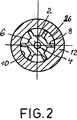
図2は図1のII−II線に沿った断面図、
図3は本発明の第2の実施の形態を示す図、そして
図4は図3のIV−IV線に沿った断面図である。
図1は内側のホース状部分2を示している。このホース状部分の中を、洗浄液用戻し通路4が延びている。ホース状部分2の外壁6には、半径方向に向いたリブ8が設けられている。このリブは外側のホース状部分12の内壁10に封止的に接続している。リブ8は押出し成形によって内側のホース状部分2と共に製作される。
外側のホース状部分12は円錐形の接着面14の領域において、半透過性(半浸透性)のホース状膜16に接続している。このホース状膜の端部18は、内側のホース状部分2の端部20と同様に、キャップ22に接着されている。このキャップは全体が接着剤滴によって形成可能である。本実施の形態において、外側のホース状部分の外径は約0.8mmである。戻し通路4は半径方向の貫通穴24を介して、リブ8の範囲に形成された供給通路26に接続している。この供給通路は図1のII−II線に沿った断面図である図2に示してある。ホース状膜16の領域内で延びる部分はゾンデと呼ばれる。
使用時に、例えば血糖値を測定するために、カテーテルは少なくともホース状膜16の一部がカニューレによって組織内に挿入される。その後、洗浄液が供給通路26を経て供給され、内側の戻し通路4から戻される。その際、洗浄液はホース状膜16の内面に沿って流れる。この場合、リブ8は周方向において供給通路26の横断面を均一にし、特にホース状膜16に対する組織の外圧に基づくあるいは戻し通路4によって発生した負圧による半透過性膜16の陥没を防止する。ホース状膜の内壁に沿って流れる液体は、膜16を通過した成分を一緒に運ぶ。この成分は戻し通路4によって戻された後で測定および分析可能である。
図3,4は図1,2と同じ図示方法で、図1,2の実施の形態の変形を示している。同じ部分または対応する部分には同じ参照符号が付けてある。違いは、図1に示した縦方向に延びるリブ8の代わりに、らせんリブ28が設けられていることにある。このらせんリブは内側のホース状部分2の外壁6に固定載置されているかあるいはこの部分と共に一つの部材を形成している。らせんリブ28の個々のねじ山の間には、洗浄液のためのらせん状の供給通路が形成され、それによって流路が延長され、所定の搬送流量の場合、ホース状膜16の領域における洗浄液の搬送速度が高まる。これにより、洗浄液によってホース状膜16の内面が均一に湿潤され、ホース状膜16を通過する成分を一緒に運ぶ作用が強まる。
らせんリブ28は任意の方法で形成可能である。らせんリブは例えば金属または合成樹脂製のらせん状線材からなっていてもよい。このらせん状線材は内側のホース状部分2に嵌められる。そして、外側のホース状部分12とホース状膜16がその上に嵌められる。The present invention relates to a catheter for measuring chemical parameters of the type described in the superordinate concept of claim 1, in particular for insertion into biological tissue, liquids and the like.
This type of catheter is known. This catheter is called a microdialysis catheter and is used to measure chemical parameters determined by microdialysis within a biological tissue, generally within the human body. A typical example of such a chemical parameter is the blood glucose content in the subcutaneous tissue. The principle of this measurement, for example as described in German Patent No. 4001760 and WO 95/32746, is to insert a double-cavity sonde into the skin. This sonde has a semi-permeable part at its tip. A lavage solution is passed through the first passage in the catheter into the sonde and flows by the semipermeable membrane while receiving blood glucose from the subcutaneous tissue. From the second passage of the catheter, this washing solution containing blood glucose is again carried out of the body, mixed with the glucose oxidase solution outside the body and supplied to the sensor. This sensor measures the reaction product of the glucose oxidase reaction. With such an apparatus, blood glucose can be continuously measured with a relatively short time delay.
Microdialysis sondes for carrying out the aforementioned measurements are known, for example, from US Pat. No. 5,106,365 and WO 95/20983. A catheter of the kind described in the superordinate concept of claim 1 is known from German Offenlegungsschrift 3,342,170. This catheter is called a dialysis sonde and comprises a dialysis membrane and a conduit for the irrigation medium through the membrane. The dialysis membrane is surrounded by a casing. This casing supports the membrane, is partially open, and is more rigid than the membrane. The conduit forms an opposing passage within the catheter. This passage ends in a hose-like membrane. The relatively stiff casing prevents the tissue from compressing the hose-like membrane after insertion of the catheter into the biological tissue and adversely affecting the function of the hose-like membrane and the flow therein. This known catheter is complex and costly to manufacture by attaching a supporting casing, and requires a relatively large diameter. Another disadvantage is that the wash flow in the hose-like membrane is not detected in the same way in all parts of the membrane.
In addition to the disadvantage that the partially permeable membrane is wetted unevenly by the liquid flow and thereby the exchange surface is very limited, there is the disadvantage that this type of sonde cannot be used under the action of suction. This is because a negative pressure is generated in the hose-like membrane, and this negative pressure causes the membrane to deflate. When used under pressure, the dead space volume acts. This causes a time delay in the measurement results. In this known sonde, apart from the time delay of the measurement results, the overall volume in the hose-like membrane is relatively large, so the ratio of the exchange surface area to the volume is small, so that in the liquid flow that flows out as a result The concentration is small and therefore must be measured at a low level.
From EP-A-401179, a catheter of the type based on the superordinate concept of claim 1 is known, in which the cylindrical walls outside the supply channel and inside the return channel are formed by rigid tubes. ing. A hard tubular membrane extends coaxially at the end of the outer rigid tube, the end of which is intimately connected to the end of the inner tubular portion by a plastic portion. The tubular membrane protrudes from the open end of the outer tubular portion and is bonded to that portion with plastic. This construction is structurally burdensome and is complicated to manufacture because the tubular membrane is connected to the outer tubular portion.
GB-A-203454 is known from a catheter of the known type, also described above, in which the inner and outer tubes are supported by support means. The end of the inner tube is fitted with a mushroom-like plug leg that protrudes above the ends of both tubes and is on the hemispherical surface of the mushroom-like portion. Has a layer of gas permeable material. This known arrangement is structurally very complex and requires multiple fabrication steps.
The problem underlying the present invention is that the above-mentioned drawbacks of the state of the art do not exist, it can be manufactured particularly easily and at low cost, has a small diameter and a dead space, and measures at a high measurement level without a large time delay It is to provide a catheter of this kind that makes it possible.
The problem underlying the present invention is solved by the features described in the characterizing part of claim 1.
The basic idea of the present invention is that the supply passage and the return passage are formed coaxially in the catheter, and the outer wall of the outer passage is formed by a semipermeable hose-like membrane in the end region of the catheter. Thereby, a small dead space is created in the hose-like membrane by filling most of the inner chamber with the cross section of the inner wall of the outer passage which is also the outer wall of the inner passage. In order to make the cross-section of this passage uniform despite the small internal width of the outer passage, while at the same time preventing the hose-like membrane from deflating in the end region of the catheter, Spacer means are provided for supporting the radially outer supply passage wall or the radially outer return passage wall. A radial through hole is provided to connect the inner passage to the outer passage at the outer end of the catheter. Thereby, in the region of the hose-like membrane, the cleaning fluid flows over the entire length of the outer passage, thereby effectively carrying away the components that have passed through the semipermeable membrane from the surrounding tissue.
The spacer means can be formed in various ways. In one embodiment, the spacer means is formed by ribs on the inner wall of the outer supply or return passage. This rib can be very easily formed when the inner part of the catheter is extruded. Subsequently, the outer part forming the outer wall of the outer passage is inserted or fitted into the inner part in the form of a hose. However, the entire catheter can be extruded together with the outer and inner portions and ribs.
In the simplest case, the rib extends in the longitudinal direction of the catheter. However, if the ribs extend in a spiral, it is very suitable. This ensures good wetting of the inner surface of the semipermeable membrane and thus the discharge of the components that pass through the semipermeable membrane. In the case of a cleaning liquid having a predetermined conveyance volume, the flow rate of the cleaning liquid is further increased by forming the ribs in a spiral shape. This allows for effective removal of components that pass through the semipermeable membrane. Since the rib fills the entire radial space of the outer passage, no leakage occurs between the outer edge of the rib and the adjacent wall .
Embodiments of the present invention will be described in detail with reference to the drawings.
FIG. 1 shows the end region of a first embodiment of a catheter according to the invention,
2 is a cross-sectional view taken along line II-II in FIG.
FIG. 3 is a diagram showing a second embodiment of the present invention, and FIG. 4 is a sectional view taken along line IV-IV in FIG.
FIG. 1 shows an inner hose-
The outer hose-
In use, for example, to measure blood glucose levels, the catheter is inserted at least a portion of the hose-
3 and 4 show a modification of the embodiment of FIGS. 1 and 2 in the same manner as in FIGS. The same or corresponding parts have the same reference numerals. The difference is that
The
Claims (7)
カテーテルを通ってその外側端部まで縦方向に延びる、液体を供給するための供給通路(26)と、
カテーテルを通って延びる、液体を戻すための戻し通路と、
カテーテルの端部に設けられ、供給通路(26)の端部と戻し通路(4)の間の流れ室を取り囲む、部分透過性の膜(16)とを備えており、
供給通路(26)が戻し通路(4)をほぼ同軸に取り囲んでいるかあるいはその逆に戻し通路(4)が供給通路(26)をほぼ同軸に取り囲んでおり、
膜(16)が少なくともカテーテルの端部の領域において、半径方向外側の戻し通路または半径方向外側の供給通路(26)の内壁(10)を形成していおり、
供給通路(26)と戻し通路(4)がカテーテルの端部において少なくとも1個の半径方向の貫通穴(24)によって互いに接続され、
供給通路(26)または戻し通路(4)が円筒形の壁で形成されているカテーテルにおいて、
部分透過性の膜(16)が、ホース状であり、
供給通路(26)の円筒形の壁がホース状部分(12)で形成され、戻し通路(4)の円筒形の壁がホース状部分(12)で形成されており、
半径方向外側のホース状部分(12)およびまたはホース状膜(16)の内壁(10)を、内側のホース状部分(2)の外壁(6)に支持するスペーサ手段が設けられており、
外側のホース状部分(12)がその全長にわたって膜材料からなり、カテーテルの前端領域を除いて不透過性層を備えていることを特徴とするカテーテル。A catheter for measuring chemical parameters, in particular for insertion into biological tissue, fluids, etc.
A supply passage (26) for supplying liquid extending longitudinally through the catheter to its outer end;
A return passage for returning liquid extending through the catheter;
A partially permeable membrane (16) provided at the end of the catheter and surrounding the flow chamber between the end of the supply passage (26) and the return passage (4) ;
The supply passage (26) surrounds the return passage (4) substantially coaxially, or vice versa, the return passage (4) surrounds the supply passage (26) substantially coaxially;
The membrane (16) forms the inner wall (10) of the radially outer return passage or the radially outer supply passage (26) at least in the region of the end of the catheter;
The supply passage (26) and the return passage (4) are connected to each other by at least one radial through hole (24) at the end of the catheter;
In a catheter in which the supply passage (26) or the return passage (4) is formed by a cylindrical wall ,
The partially permeable membrane (16) is hose-shaped,
The cylindrical wall of the supply passage (26) is formed by a hose-like part (12), the cylindrical wall of the return passage (4) is formed by a hose-like part (12);
Spacer means are provided for supporting the radially outer hose-like part (12) and / or the inner wall (10) of the hose-like membrane (16) on the outer wall (6) of the inner hose-like part (2) ;
Catheter characterized in that the outer hose-like part (12) is made of membrane material over its entire length and is provided with an impermeable layer except for the front end region of the catheter.
Applications Claiming Priority (3)
| Application Number | Priority Date | Filing Date | Title |
|---|---|---|---|
| DE19714572.8 | 1997-04-09 | ||
| DE19714572A DE19714572C1 (en) | 1997-04-09 | 1997-04-09 | Catheter for measuring chemical parameters in biological tissue |
| PCT/EP1998/001906 WO1998044978A1 (en) | 1997-04-09 | 1998-04-02 | Catheter for measuring chemical parameters, in particular for introducing into biological tissues, liquids or the like |
Publications (3)
| Publication Number | Publication Date |
|---|---|
| JP2001521419A JP2001521419A (en) | 2001-11-06 |
| JP2001521419A5 JP2001521419A5 (en) | 2005-09-08 |
| JP3892050B2 true JP3892050B2 (en) | 2007-03-14 |
Family
ID=7825854
Family Applications (1)
| Application Number | Title | Priority Date | Filing Date |
|---|---|---|---|
| JP54235398A Expired - Fee Related JP3892050B2 (en) | 1997-04-09 | 1998-04-02 | Catheter for measuring chemical parameters, especially for insertion into biological tissues, fluids, etc. |
Country Status (8)
| Country | Link |
|---|---|
| US (1) | US6616625B2 (en) |
| EP (1) | EP0973573B1 (en) |
| JP (1) | JP3892050B2 (en) |
| AT (1) | ATE318631T1 (en) |
| AU (1) | AU7428298A (en) |
| DE (2) | DE19714572C1 (en) |
| ES (1) | ES2256938T3 (en) |
| WO (1) | WO1998044978A1 (en) |
Families Citing this family (15)
| Publication number | Priority date | Publication date | Assignee | Title |
|---|---|---|---|---|
| DE19725680C2 (en) | 1997-06-18 | 2000-04-06 | Hans Haindl | Funnel-shaped cannula arrangement for catheter insertion |
| DE10000823A1 (en) * | 2000-01-12 | 2001-07-19 | Hartwin Hobler | Apparatus for introduction of a gas into a body fluid, a tissue fluid or a culture fluid comprises a channel with a gas outlet opening which is closed by means of gas-permeable barrier element |
| SE519630C2 (en) | 2001-08-30 | 2003-03-18 | Gambro Lundia Ab | Catheter and method of manufacture thereof |
| DE10246207B4 (en) | 2002-10-04 | 2008-04-03 | Disetronic Licensing Ag | Microdialysis probe with spiral line |
| DE10247023B4 (en) * | 2002-10-09 | 2006-07-20 | Disetronic Licensing Ag | Microdialysis probe and method for its production |
| DE102005007901A1 (en) * | 2005-02-21 | 2006-08-31 | Roche Diagnostics Gmbh | Catheter with microchannels for monitoring the concentration of an analyte in a body fluid |
| GB2442209B (en) * | 2006-09-28 | 2012-01-18 | Probe Scient Ltd | Molecular exchange device |
| EP2077762B8 (en) * | 2006-10-18 | 2014-09-17 | Maquet Critical Care AB | Microdialysis catheter and a method of making a microdialysis catheter |
| EP1922987A1 (en) | 2006-11-17 | 2008-05-21 | Trace Analytics GmbH | Sampling device and sampling method |
| GB2457469B (en) * | 2008-02-13 | 2012-11-07 | Probe Scient Ltd | Molecular exchange device |
| GB2457468B (en) * | 2008-02-13 | 2012-11-21 | Probe Scient Ltd | molecular exchange device |
| EP2559450A1 (en) * | 2011-08-19 | 2013-02-20 | Abbott Laboratories Vascular Enterprises Limited | Shaft for medical devices and catheter |
| EP2903514B1 (en) * | 2012-10-02 | 2022-11-23 | Lutz Freitag | Systems for pulmonary diagnosis |
| DE102014226628A1 (en) | 2014-12-19 | 2016-06-23 | Raumedic Ag | Multi-lumen microcatheter tube and method of making a multi-lumen microcatheter tube |
| WO2022061280A1 (en) * | 2020-09-21 | 2022-03-24 | University Of Connecticut | Implantable medical devices with enhanced biocompatibility |
Family Cites Families (19)
| Publication number | Priority date | Publication date | Assignee | Title |
|---|---|---|---|---|
| DE2305640C3 (en) | 1973-02-06 | 1975-08-14 | B. Braun Melsungen Ag, 3508 Melsungen | Device for introducing flexible catheters |
| US4274417A (en) * | 1978-09-22 | 1981-06-23 | National Research Development Corporation | Instruments for use in the measurement of gases in body fluids |
| DE3147609A1 (en) | 1981-12-02 | 1983-06-16 | B. Braun Melsungen Ag, 3508 Melsungen | Insertion device for introduction of elongate articles into a blood vessel |
| JPS5978502U (en) | 1982-11-16 | 1984-05-28 | クラリオン株式会社 | car stereo mounting device |
| SE434214B (en) * | 1982-12-01 | 1984-07-16 | Carl Urban Ungerstedt | DIALYSIS PROBLEM, INTENDED FOR INFORMATION IN BIOLOGICAL Tissues |
| US5021044A (en) * | 1989-01-30 | 1991-06-04 | Advanced Cardiovascular Systems, Inc. | Catheter for even distribution of therapeutic fluids |
| AT393213B (en) * | 1989-02-08 | 1991-09-10 | Avl Verbrennungskraft Messtech | DEVICE FOR DETERMINING AT LEAST ONE MEDICAL MEASURING SIZE |
| IT1231916B (en) | 1989-05-29 | 1992-01-15 | Ampliscientifica S R L | WEARABLE ARTIFICIAL PANCREAS |
| FR2648353B1 (en) * | 1989-06-16 | 1992-03-27 | Europhor Sa | MICRODIALYSIS PROBE |
| FR2655548A1 (en) * | 1989-12-11 | 1991-06-14 | Cleef Jean Francois Van | Catheter with walls which are not smooth (catheter with walls which are moulded) |
| CA2094414C (en) | 1992-04-21 | 2007-03-27 | Joseph J. Chang | Intravenous catheter with needle guard |
| SE502537C2 (en) | 1992-11-26 | 1995-11-06 | Boc Ohmeda Ab | Device for infusion cannula |
| CA2132890C (en) | 1993-09-30 | 1999-04-06 | Timothy J. Erskine | Peristaltic interlumenar device advancer |
| SE502438C2 (en) * | 1994-02-04 | 1995-10-16 | Cma Microdialysis Holding Ab | Reinforced microdialysis probe |
| SE502394C2 (en) | 1994-02-04 | 1995-10-16 | Cma Microdialysis Holding Ab | Dialysis probe combination as well as microdialysis probe and cannula for the combination |
| CA2167733A1 (en) | 1994-05-26 | 1995-12-07 | Ray D. Hoffman | Process for reclaiming crosslinked acrylic scrap |
| US5441481A (en) * | 1994-05-27 | 1995-08-15 | Mishra; Pravin | Microdialysis probes and methods of use |
| US5501675A (en) | 1994-12-27 | 1996-03-26 | Becton, Dickinson And Company | Safety catheter assembly having safety stop push button |
| US5586553A (en) | 1995-02-16 | 1996-12-24 | Minimed Inc. | Transcutaneous sensor insertion set |
-
1997
- 1997-04-09 DE DE19714572A patent/DE19714572C1/en not_active Expired - Fee Related
-
1998
- 1998-04-02 WO PCT/EP1998/001906 patent/WO1998044978A1/en active IP Right Grant
- 1998-04-02 JP JP54235398A patent/JP3892050B2/en not_active Expired - Fee Related
- 1998-04-02 AT AT98921414T patent/ATE318631T1/en not_active IP Right Cessation
- 1998-04-02 ES ES98921414T patent/ES2256938T3/en not_active Expired - Lifetime
- 1998-04-02 AU AU74282/98A patent/AU7428298A/en not_active Abandoned
- 1998-04-02 DE DE59813418T patent/DE59813418D1/en not_active Expired - Fee Related
- 1998-04-02 EP EP98921414A patent/EP0973573B1/en not_active Expired - Lifetime
- 1998-04-02 US US09/402,342 patent/US6616625B2/en not_active Expired - Fee Related
Also Published As
| Publication number | Publication date |
|---|---|
| JP2001521419A (en) | 2001-11-06 |
| DE19714572C1 (en) | 1998-06-25 |
| ATE318631T1 (en) | 2006-03-15 |
| AU7428298A (en) | 1998-10-30 |
| WO1998044978A1 (en) | 1998-10-15 |
| DE59813418D1 (en) | 2006-04-27 |
| EP0973573A1 (en) | 2000-01-26 |
| US6616625B2 (en) | 2003-09-09 |
| EP0973573B1 (en) | 2006-03-01 |
| US20030060751A1 (en) | 2003-03-27 |
| ES2256938T3 (en) | 2006-07-16 |
Similar Documents
| Publication | Publication Date | Title |
|---|---|---|
| JP3892050B2 (en) | Catheter for measuring chemical parameters, especially for insertion into biological tissues, fluids, etc. | |
| CA1212286A (en) | Long indwelling double bore catheter | |
| US4274417A (en) | Instruments for use in the measurement of gases in body fluids | |
| JP6940591B2 (en) | Oxygen measurement device and oxygen measurement system | |
| CA1241580A (en) | Volumetric flow rate determination in conduits not directly accessible | |
| EP0570938A2 (en) | Catheter and probe-catheter assembly | |
| JP6920419B2 (en) | Monitoring system and oxygen measurement system | |
| JPWO2017213237A1 (en) | Oxygen measuring device | |
| DE59907290D1 (en) | INJECTOR FOR APPLICATING LIQUIDS WITH A PRESSURE MEASUREMENT SYSTEM | |
| NL8003300A (en) | Apparatus for the analysis of absorbed gases. | |
| US2492384A (en) | Stomach irrigation tube | |
| AU2007321186B2 (en) | Sample taking device, and sample taking methods | |
| US7828763B2 (en) | Microdialysis probe with a spiral line | |
| US20050119588A1 (en) | Microdialysis probe with inserting means and assembly | |
| CN105997100A (en) | Molecular exchange device | |
| US6186975B1 (en) | Liquid conveying catheter | |
| JP6472487B2 (en) | Steel tube with measuring element | |
| KR101874558B1 (en) | Urethal catheter | |
| US9534493B2 (en) | Pressure measurement cell for use in an infusion or injection system | |
| JP7091770B2 (en) | Intra-aortic balloon catheter | |
| JP2021062073A (en) | Catheter and oxygen partial pressure measuring method | |
| EP1217944B1 (en) | Sensor for measuring tissue perfusion | |
| US8585984B2 (en) | Proboscis for use with a diagnostic instrument | |
| US20060129131A1 (en) | Catheter | |
| JPH06160331A (en) | Flow-through type ph electrode |
Legal Events
| Date | Code | Title | Description |
|---|---|---|---|
| A521 | Request for written amendment filed |
Free format text: JAPANESE INTERMEDIATE CODE: A523 Effective date: 20050121 |
|
| A621 | Written request for application examination |
Free format text: JAPANESE INTERMEDIATE CODE: A621 Effective date: 20050121 |
|
| A711 | Notification of change in applicant |
Free format text: JAPANESE INTERMEDIATE CODE: A711 Effective date: 20051219 |
|
| A131 | Notification of reasons for refusal |
Free format text: JAPANESE INTERMEDIATE CODE: A131 Effective date: 20060725 |
|
| A521 | Request for written amendment filed |
Free format text: JAPANESE INTERMEDIATE CODE: A523 Effective date: 20061006 |
|
| TRDD | Decision of grant or rejection written | ||
| A01 | Written decision to grant a patent or to grant a registration (utility model) |
Free format text: JAPANESE INTERMEDIATE CODE: A01 Effective date: 20061121 |
|
| A61 | First payment of annual fees (during grant procedure) |
Free format text: JAPANESE INTERMEDIATE CODE: A61 Effective date: 20061206 |
|
| R150 | Certificate of patent or registration of utility model |
Free format text: JAPANESE INTERMEDIATE CODE: R150 |
|
| FPAY | Renewal fee payment (event date is renewal date of database) |
Free format text: PAYMENT UNTIL: 20091215 Year of fee payment: 3 |
|
| FPAY | Renewal fee payment (event date is renewal date of database) |
Free format text: PAYMENT UNTIL: 20101215 Year of fee payment: 4 |
|
| LAPS | Cancellation because of no payment of annual fees |