JP3891237B2 - COMMUNICATION DATA MONITORING DEVICE, COMMUNICATION DATA MONITORING METHOD, AND RECORDING MEDIUM CONTAINING COMMUNICATION DATA MONITORING PROGRAM - Google Patents
COMMUNICATION DATA MONITORING DEVICE, COMMUNICATION DATA MONITORING METHOD, AND RECORDING MEDIUM CONTAINING COMMUNICATION DATA MONITORING PROGRAM Download PDFInfo
- Publication number
- JP3891237B2 JP3891237B2 JP10974598A JP10974598A JP3891237B2 JP 3891237 B2 JP3891237 B2 JP 3891237B2 JP 10974598 A JP10974598 A JP 10974598A JP 10974598 A JP10974598 A JP 10974598A JP 3891237 B2 JP3891237 B2 JP 3891237B2
- Authority
- JP
- Japan
- Prior art keywords
- communication data
- trigger signal
- signal output
- communication
- data analysis
- Prior art date
- Legal status (The legal status is an assumption and is not a legal conclusion. Google has not performed a legal analysis and makes no representation as to the accuracy of the status listed.)
- Expired - Fee Related
Links
Images

Landscapes
- Monitoring And Testing Of Exchanges (AREA)
- Data Exchanges In Wide-Area Networks (AREA)
- Maintenance And Management Of Digital Transmission (AREA)
- Monitoring And Testing Of Transmission In General (AREA)
Description
【0001】
【発明の属する技術分野】
本発明は、通信回線に接続され回線上の通信データを解析する通信データ解析装置に関する。
【0002】
【従来の技術】
ネットワークシステムにおける通信異常要因には、プロトコルデータの誤りや通信手順の誤りなどソフトウェアによる要因(ソフトウェア要因)と、伝送波形の歪みや減衰などハードウェアによる要因(ハードウェア要因)とがある。
【0003】
このうち、ソフトウェア要因の解析には、受信データが正常か異常かの判定や、異常を検出した時における通信データの内容を解析する手段として通信データ解析装置が使用される。一方、ハードウェア要因の解析には、一般にオシロスコープなどの伝送波形測定装置が使用される。
【0004】
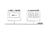
図6は、通信データ解析装置と伝送波形測定装置とを使用した従来のネットワークの解析システムを示す図である。通信データ解析装置1Aと伝送波形測定装置2Aとは伝送路上の近接した位置に配置され、伝送路上の同じデータを観測する。
【0005】
【発明が解決しようとする課題】
通常、伝送波形測定装置によって波形を観測するとき、波形観測のタイミングで伝送波形測定装置にトリガ信号を入力することが必要である。しかし、図6に示されている従来の通信データ解析装置は、外部への信号出力装置を具備していないので、通信データ解析装置によって検出された解析データと伝送波形測定装置によって表示される伝送波形との同期をとることができなかった。その結果、通信データ解析装置による解析結果と伝送波形との間の関連、例えば、通信データ解析装置での異常検出時の伝送波形を直接観察ことは不可能であった。
【0006】
このような理由で、通信データ解析装置で異常検出時の伝送波形を観察するには、通信データ解析装置で採取したデータパターンに基いて、伝送波形測定装置のトリガ条件を算出しなければならず、ネットワークの異常要因解析を困難にさせていた。
【0007】
特開平7−162514号公報(以下、引用公報と記す)には、同公報に記載されている発明の動機として、「常時発生している異常現象に対しては、その異常現象を信号波形等で簡単に特定でき、異常原因の究明も比較的短時間で実施できる。しかし、単発的に発生する異常現象は、たとえ、この通信システムを熟知した技術者であったとしても簡単に再現できなく、異常現象の特定および異常原因究明に多大の時間と労力が必要であった。」と記載されている。
【0008】
このような背景のもとで、引用公報は、異常現象を信号波形で特定することを一応断念し、異常が発生した時に、その異常発生から所定時間だけ溯った時間帯における監視情報、すなわち、最新の、最小限の監視情報を収集し、その監視情報から異常原因を究明する、ネットワーク監視システムの情報検索装置を開示している。
【0009】
しかし、信号波形の測定は、異常現象を簡単に特定して比較的短時間で異常原因の究明を実施するために有効な方法であることには変わりない。本発明の目的は、単発的または低頻度不定期の異常の発生を検出したとき、その検出時の伝送波形を観測することができる通信データ監視装置を提供することにある。本発明の他の目的は、任意に指定されたデータパターンの到来を検出し、特定局からの送信データのみを観測することができる特定通信受信装置を提供することにある。
【0010】
【課題を解決するための手段】
上記の目的を達成するために、本発明の通信データ監視装置は、通信回線上の通信データを入力して、該入力した通信データについて、予め定められた調査項目に関する所定の通信データ解析を行う通信データ解析装置と、通信回線上の通信データを入力して、当該入力した通信データの波形を表示する伝送波形測定装置とを有する通信データ監視装置であって、
前記通信データ解析装置は、前記所定の通信データ解析を行って得られた解析結果から、当該通信データが波形表示を必要とすることを判定する基準として予め定められた、任意のオフセットアドレス、任意のビットパターンを有する比較データ、および該比較データのビットパターンに対応する、通信データの比較対象ビットを抽出するデータマスクをトリガ信号出力条件として設定し、前記所定の通信データ解析の結果が前記トリガ信号出力条件を満たすか否かを判定し、その判定結果に対応してトリガ信号の出力を制御する情報処理装置と、前記情報処理装置の制御に応答してトリガ信号を、専用線を介して出力するトリガ信号出力装置を有し、
前記伝送波形測定装置は、前記専用線を介してトリガ信号を入力して、該トリガ信号に同期して通信回線上の通信データの伝送波形を表示する表示手段を有する。
【0011】
本発明の通信データ監視方法は、通信回線上の通信データを入力して、当該入力した通信データについて、予め定められた調査項目に関する所定の通信データ解析を行う通信データ解析処理と、通信回線上の通信データを入力して、当該入力した通信データの波形を表示する伝送波形表示処理とを含む通信データ監視方法であって、
前記通信データ解析処理は、前記所定の通信データ解析を行って得られた解析結果から当該通信データが波形表示を必要とすることを判定する基準として予め定められた、任意のオフセットアドレス、任意のビットパターンを有する比較データ、および該比較データのビットパターンに対応する、通信データの比較対象ビットを抽出するデータマスクをトリガ信号出力条件として設定し、前記所定の通信データ解析の結果が前記トリガ信号出力条件を満たすか否かを判定し、その判定結果に対応してトリガ信号の専用線への出力を制御する処理を含み、
前記伝送波形表示処理は、前記通信データ解析処理によって生成されたトリガ信号を前記専用線から入力して、該トリガ信号に同期して通信回線上の通信データの伝送波形を表示する処理を含む。
【0012】
トリガ信号出力条件として受信エラー要因を設定することができる。また、トリガ信号出力条件を内部データ形式で設定し、内部データとして任意のオフセットアドレス、任意のビットパターンを有する比較データ、および当該比較データのビットパターンに対応する当該通信データの比較対象ビットを抽出するデータマスクを設定することができる。
【0013】
【作用】
このように、通信データ解析を行って得られた解析結果から当該通信データが波形表示を必要とすることを判定する基準として予め定められた条件をトリガ信号出力条件として設定し、前記所定の通信データ解析の結果が前記トリガ信号出力条件を満たす場合にはトリガ信号を生成し、そのトリガ信号に同期して伝送波形を表示するので、例えば、単発または低頻度不定期の原因でトリガ信号出力条件を満たすことになった通信データが到来した場合であっても、トリガ信号出力条件の検出タイミングで伝送波形を採取することができる。
【0014】
トリガ信号出力条件のデータとして、受信エラー要因と、通信データの先頭からのオフセットアドレス、データマスク、比較データを採用することにより、伝送波形測定装置は、受信異常検出時だけでなく、任意のオフセットアドレスで任意のビットパターンを含むデータ受信のタイミングに同期して伝送波形の表示を開始することができる。
【0015】
【発明の実施の形態】
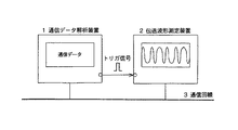
図1は、本発明の通信データ監視装置の実施形態の一例を示すシステム図である。本実施形態の通信データ監視装置は、基本的に通信データ解析装置1、伝送波形測定装置2および通信データ監視装置に所定の処理を実行させるための制御プログラムを記録した記録媒体(図示せず)から成っている。
【0016】
通信データ解析装置1は、通信回線上の通信データを入力してその通信データの正常または異常の判定および異常検出時における通信データの内容の解析を含む所定の通信データ解析を行う。伝送波形測定装置は、通信回線上の通信データを入力して受信した通信データの波形を表示する。
【0017】
本発明の通信データ監視装置が図6の装置と異なる点は、通信データが予め設定された条件を満たすときには、通信データ解析装置1が外部へトリガ信号を出力し、伝送波形測定装置2は、通信回線3の波形観測用トリガとして通信データ解析装置1から出力されるトリガ信号を入力し、該トリガ信号に同期して波形を表示する点にある。
【0018】
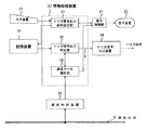
図2は、本実施形態の通信データ解析装置のブロック図である。
本実施形態の通信データ解析装置1は入力装置21、記憶装置22、情報処理装置23、通信制御装置24、表示装置25、表示制御部27およびトリガ信号出力装置26を備えている。情報処理装置23は、トリガ信号出力条件設定部31、トリガ信号出力判定部32、および通信データ解析部33を備えている。
【0019】
入力装置21は、オペレータによって入力されたトリガ信号出力条件を所定の信号形式に変換して情報処理装置23の出力条件判定部31に伝達する。トリガ信号出力条件設定部31は、入力装置1から入力されたトリガ信号出力条件を所定のデータ形式(後述の図5参照)に変換して記憶装置22に出力する。記憶装置22はトリガ信号出力条件を保持する。
【0020】
通信制御装置24は通信回線3上の伝送データを受信して情報処理装置23に伝達するための入力制御を行う。通信データ解析部33は通信制御装置24から受信した通信データの正常受信または異常受信の判定、伝文の解析、または、その他の所定の通信データ解析を行う。トリガ信号出力判定部32は、通信データ解析部33による解析結果(解析データ)を、記憶装置22に記憶されているトリガ信号出力条件と比較し、トリガ信号出力条件が成立した場合にはトリガ信号の出力を指示する指示信号Sを出力する。トリガ信号出力装置26は、指示信号Sを受信すると、該指示信号に応答して伝送波形測定装置2に対してトリガ信号を出力する。
【0021】
伝送波形測定装置2はトリガ信号出力装置26を介して通信データ解析装置1と接続されていて、通信データ解析装置1からのトリガ信号を入力することができる。伝送波形測定装置2はトリガ信号を受信すると、トリガ信号に同期して到来している通信データの波形を表示する。
【0022】
表示制御部27は入力されるデータ信号の表示制御を行う。表示装置25は、表示制御部27の制御に従って、入力情報を表示する。本実施形態においては、表示装置25は次の情報を表示する。
▲1▼トリガ信号出力条件設定部31によってトリガ信号出力条件が設定された時に、その設定条件を表示する。
▲2▼通信データ解析部が通信記憶装置(図示せず)に保存した受信データを表示する。(通信データ解析部33は通信制御装置24から受信データを取出し通信記憶装置に保存する。トリガ信号出力判定部32は、トリガ信号出力条件成立時には通信データ解析部33の通信記憶装置への受信データ保存を停止させることができる。)
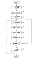
次に、図3を参照して本実施形態の動作を説明する。図3は、本実施形態の情報処理装置23の動作を説明するフローチャートである。
情報処理装置23は、予め、トリガ信号出力条件を入力して記憶装置22に登録する(ステップS1)。データ解析開始要求を受領すると通信データの解析を開始し(ステップS2)、記憶装置22からトリガ信号出力条件を読み出す(ステップS3)。次に、情報処理装置23は通信データを受信するまで待機する(ステップS4)。情報処理装置23は通信回線3上の伝送データを通信制御装置24を介して受信すると(ステップS5)、通信データ解析部33にて正常受信または異常受信の判定、伝文の解析、またはその他の所定調査項目について通信データ解析を行う(ステップS6)。情報処理装置23は、解析された受信データを記憶装置22から読み出したトリガ信号出力条件と比較してトリガ信号を出力すべきか否かを判定する(ステップS7)。トリガ信号出力条件が成立しない場合(ステップS8)には、次の通信データの受信待ち状態になる(ステップS4)。トリガ信号出力条件が成立した場合(ステップS8)には、トリガ信号出力装置26に対してトリガ信号の出力を指示する指示信号Sを送出し(ステップS9)、次の通信データの受信待ち状態になる(ステップS4)。
【0023】
トリガ信号出力装置26は指示信号に応答してトリガ信号を出力する。伝送波形測定装置2は入力したトリガ信号に同期して伝送波形を表示する。
【0024】
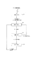
図4は、図2における情報処理装置23の通信データ解析中の状態遷移図である。
情報処理装置23は、データ解析開始要求を受領すると、READ_TRIG状態に遷移し(遷移T1)、記憶装置からトリガ信号出力条件の読出しを実行する。トリガ信号出力条件の読出しが終了すると、情報処理装置は、WAIT_RECV状態に遷移し(遷移T2)、通信制御装置からのデータ受信通知を待つ。情報処理装置は、データ受信通知を受領するとCOMP_DATA状態に遷移し(遷移T3)、受信データとREAD_TRIG状態で読み出したトリガ信号出力条件との比較を行う。ここでトリガ信号出力条件が成立した場合にはOUT_TRIG状態に遷移し(遷移T4)、トリガ信号出力装置へトリガ信号の出力を指示する。トリガ信号出力条件が成立しなかった場合にはWAIT_RECV状態に戻り次の受信データを待つ。
【0025】
図5は、図2における記憶装置22に保存されるトリガ信号出力条件の内部データ形式の例である。
トリガ信号出力条件には、受信エラー検出時にエラー内容を限定するトリガ出力エラー条件51の他に、特定データ受信時をトリガ信号出力条件として指定するトリガ出力データ条件52がある。
【0026】
トリガエラー条件51として何を設定するかは調査する異常現象や調査の過程で異なる。例えば、伝送路の異常によるノイズの影響の疑いが強い場合なら、全てのエラーをトリガ信号出力条件とすればよいし、中継器の誤動作の疑いが強い場合なら、アライメントエラーに絞り込むことができる。また、ソフトウェアの誤りの可能性が高い場合は、ハードウエア要因によるエラーではなく特定データに関してトリガ信号出力条件が設定されることになる。
【0027】
本実施形態においては、トリガ出力エラー条件51としてショートパケットエラー、アライメントエラー、およびCRCエラーが使用されている。
【0028】
トリガ出力データ条件52は、本実施形態においては、通信データ上の任意のオフセットアドレスと任意のビットパターンを指定するために通信データオフセットアドレス54、比較データマスク55および比較データ56から構成されている。これらの条件から、トリガ信号は、受信データのオフセットアドレス54の内容と比較データマスク55の論理積と比較データが一致した場合に出力される。トリガ出力データ条件は、複数設定可能で、設定された条件の論理組み合わせが判定に使用される。
【0029】
トリガ信号出力データ条件52を適用する一実施例として、通信回線上に局A,Bの2局が接続されていて、局Aから局Bへ送信したある要求を局Bが受信できない場合を考える。この要求は、
▲1▼伝送データの先頭から相対1バイト目に、送信先アドレス0BH、
▲2▼伝送データの先頭から相対2バイト目に、送信元アドレス0AH、
▲3▼伝送データの先頭から相対3バイト目の0,1ビットに10Bの要求コードを含んでいるとする。
この場合、トリガ信号出力条件は
(a)オフセット:0H、 比較データマスク:FFH、 比較データ:OBH (▲1▼用)
(b)オフセット:1H、 比較データマスク:FFH、 比較データ:0AH (▲2▼用)
(c) オフセット:2H、 比較データマスク:00000011B、 比較データ:10B (▲3▼用)
に設定される。
トリガ信号出力条件設定後、本実施形態の通信データ監視装置を局Aの接続端付近の伝送路に接続することによって、トリガ信号の出力の有無から局Aが伝送路に通信データを正しく送出したかを確認することができる。トリガ信号が出力されない場合には、エラー原因を局Aのソフトウェアまたは通信制御装置の誤りに限定することができる。
【0030】
【発明の効果】
以上に述べたように本発明は次の効果を有する。
調査項目に応じて予め定められた条件を、トリガ信号出力条件として設定し、通信データ解析の結果がトリガ信号出力条件を満たすか否かの判定結果に対応してトリガ信号の出力を制御することによって、通信データ解析装置の異常検出タイミングで伝送波形が採取することができ、それによって、ネットワークシステムで検出した異常の要因を解析することができる。
また、トリガ信号出力条件の設定に任意のデータパターンを指定することによって、特定局からのデータのみを観測する特定信号受信装置を提供することができる。
【図面の簡単な説明】
【図1】本発明の実施例を示すシステム図である。
【図2】本発明の一実施形態の構成を示すブロック図である。
【図3】図2の装置の動作を説明するフローチャートである。
【図4】図2の情報処理部の状態遷移図である。
【図5】本発明の実施形態におけるトリガ信号出力条件として記憶装置に記憶されているデータの一形式を示す図である。
【図6】従来技術の一例を示すシステム図である。
【符号の説明】
1、1A 通信データ解析装置
2,2A 伝送波形測定装置
3 通信回線
21 入力装置
22 記憶装置
23 情報処理装置
24 通信制御装置
25 表示装置
26 トリガ信号出力装置
27 表示制御部
31 トリガ信号出力条件設定部
32 トリガ信号出力判定部
33 通信データ解析部
51 トリガ出力エラー条件
52 トリガ出力データ条件
53 トリガ出力エラー条件のデータ形式
54 通信データオフセットアドレス
55 比較データマスク
56 比較データ[0001]
BACKGROUND OF THE INVENTION
The present invention relates to a communication data analyzing apparatus that is connected to a communication line and analyzes communication data on the line.
[0002]
[Prior art]
Communication error factors in a network system include software factors (software factors) such as protocol data errors and communication procedure errors, and hardware factors (hardware factors) such as transmission waveform distortion and attenuation.
[0003]
Among these, for analysis of software factors, a communication data analysis device is used as means for determining whether received data is normal or abnormal and analyzing the contents of communication data when an abnormality is detected. On the other hand, a transmission waveform measuring device such as an oscilloscope is generally used for analyzing hardware factors.
[0004]
FIG. 6 is a diagram showing a conventional network analysis system using a communication data analysis device and a transmission waveform measurement device. The communication data analyzing apparatus 1A and the transmission waveform measuring apparatus 2A are arranged at close positions on the transmission path, and observe the same data on the transmission path.
[0005]
[Problems to be solved by the invention]
Normally, when a waveform is observed by the transmission waveform measuring device, it is necessary to input a trigger signal to the transmission waveform measuring device at the timing of waveform observation. However, since the conventional communication data analysis device shown in FIG. 6 does not include an external signal output device, the analysis data detected by the communication data analysis device and the transmission displayed by the transmission waveform measurement device. It was not possible to synchronize with the waveform. As a result, it has been impossible to directly observe the relationship between the analysis result by the communication data analysis device and the transmission waveform, for example, the transmission waveform at the time of abnormality detection in the communication data analysis device.
[0006]
For this reason, in order to observe the transmission waveform when an abnormality is detected by the communication data analysis device, the trigger condition of the transmission waveform measurement device must be calculated based on the data pattern collected by the communication data analysis device. , Making it difficult to analyze network anomalies.
[0007]
In Japanese Patent Laid-Open No. 7-162514 (hereinafter referred to as a cited publication), the motive of the invention described in the publication is “For an abnormal phenomenon that occurs constantly, the abnormal phenomenon is indicated by a signal waveform, etc. It is easy to identify the cause of an abnormality, and it is possible to investigate the cause of an abnormality in a relatively short time.However, an abnormal phenomenon that occurs once cannot be easily reproduced even by an engineer familiar with this communication system. "It took a lot of time and effort to identify the abnormal phenomenon and investigate the cause of the abnormality."
[0008]
Under such a background, the cited publication abandoned to specify an abnormal phenomenon with a signal waveform, and when an abnormality occurs, monitoring information in a time zone that has been given for a predetermined time from the occurrence of the abnormality, that is, An information retrieval apparatus for a network monitoring system that collects the latest and minimum monitoring information and investigates the cause of the abnormality from the monitoring information is disclosed.
[0009]
However, the measurement of the signal waveform is still an effective method for easily identifying an abnormal phenomenon and investigating the cause of the abnormality in a relatively short time. An object of the present invention is to provide a communication data monitoring device capable of observing a transmission waveform at the time of detection of occurrence of a single or infrequent irregular occurrence. Another object of the present invention is to provide a specific communication receiver capable of detecting the arrival of an arbitrarily designated data pattern and observing only transmission data from a specific station.
[0010]
[Means for Solving the Problems]
In order to achieve the above object, the communication data monitoring apparatus of the present invention inputs communication data on a communication line and performs predetermined communication data analysis on a predetermined investigation item for the input communication data. A communication data monitoring device having a communication data analysis device and a transmission waveform measuring device that inputs communication data on a communication line and displays a waveform of the input communication data,
The communication data analyzing apparatus is configured to determine an arbitrary offset address, an arbitrary predetermined address as a reference for determining that the communication data requires waveform display from an analysis result obtained by performing the predetermined communication data analysis. And a data mask for extracting a comparison target bit of communication data corresponding to the bit pattern of the comparison data is set as a trigger signal output condition, and the result of the predetermined communication data analysis is the trigger An information processing device that determines whether or not a signal output condition is satisfied and controls the output of the trigger signal in response to the determination result, and the trigger signal in response to the control of the information processing device via a dedicated line Having a trigger signal output device for outputting,
The transmission waveform measuring apparatus has display means for inputting a trigger signal through the dedicated line and displaying a transmission waveform of communication data on a communication line in synchronization with the trigger signal.
[0011]
The communication data monitoring method according to the present invention includes a communication data analysis process for inputting communication data on a communication line and performing predetermined communication data analysis on a predetermined investigation item for the input communication data; A communication waveform monitoring process including a transmission waveform display process for displaying the waveform of the input communication data,
The communication data analysis process includes an arbitrary offset address, an arbitrary offset address, which is predetermined as a criterion for determining that the communication data requires waveform display from an analysis result obtained by performing the predetermined communication data analysis . A comparison data having a bit pattern and a data mask for extracting a comparison target bit of communication data corresponding to the bit pattern of the comparison data are set as trigger signal output conditions, and the result of the predetermined communication data analysis is the trigger signal Including determining whether the output condition is satisfied, and controlling the output of the trigger signal to the dedicated line according to the determination result,
The transmission waveform display process, said trigger signal generated by the communication data analyzing process input from the dedicated line, the process including displaying a transmission waveform of the communication data on the communication line in synchronization with the trigger signal .
[0012]
A reception error factor can be set as a trigger signal output condition. Also, trigger signal output conditions are set in the internal data format, and the internal data is extracted with any offset address, comparison data having an arbitrary bit pattern, and the comparison target bit of the communication data corresponding to the bit pattern of the comparison data Data mask to be set can be set.
[0013]
[Action]
As described above, a predetermined condition is set as a trigger signal output condition as a criterion for determining that the communication data requires waveform display from the analysis result obtained by performing the communication data analysis, and the predetermined communication is performed. If the result of data analysis satisfies the trigger signal output condition, a trigger signal is generated and the transmission waveform is displayed in synchronization with the trigger signal. Even when communication data that satisfies the conditions has arrived, a transmission waveform can be collected at the detection timing of the trigger signal output condition.
[0014]
By adopting the reception error factor, the offset address from the beginning of the communication data, the data mask, and the comparison data as the trigger signal output condition data, the transmission waveform measurement device can set an arbitrary offset not only when a reception error is detected. Transmission waveform display can be started in synchronization with the timing of data reception including an arbitrary bit pattern at the address.
[0015]
DETAILED DESCRIPTION OF THE INVENTION
FIG. 1 is a system diagram showing an example of an embodiment of a communication data monitoring apparatus of the present invention. The communication data monitoring apparatus according to the present embodiment is basically a recording medium (not shown) in which a control program for causing the communication
[0016]
The communication
[0017]
The communication data monitoring device of the present invention is different from the device of FIG. 6 in that when the communication data satisfies a preset condition, the communication
[0018]
FIG. 2 is a block diagram of the communication data analysis apparatus of this embodiment.
The communication
[0019]
The
[0020]
The
[0021]
The transmission
[0022]
The
(1) When a trigger signal output condition is set by the trigger signal output
(2) The received data stored in the communication storage device (not shown) by the communication data analysis unit is displayed. (The communication
Next, the operation of this embodiment will be described with reference to FIG. FIG. 3 is a flowchart for explaining the operation of the information processing apparatus 23 of the present embodiment.
The information processing device 23 inputs a trigger signal output condition in advance and registers it in the storage device 22 (step S1). When a data analysis start request is received, analysis of communication data is started (step S2), and trigger signal output conditions are read from the storage device 22 (step S3). Next, the information processing apparatus 23 stands by until communication data is received (step S4). When the information processing device 23 receives the transmission data on the communication line 3 via the communication control device 24 (step S5), the communication
[0023]
The trigger
[0024]
FIG. 4 is a state transition diagram during communication data analysis of the information processing apparatus 23 in FIG.
When the information processing device 23 receives the data analysis start request, the information processing device 23 transitions to the READ_TRIG state (transition T1), and reads the trigger signal output condition from the storage device. When the reading of the trigger signal output condition is completed, the information processing apparatus transitions to the WAIT_RECV state (transition T2) and waits for a data reception notification from the communication control apparatus. When receiving the data reception notification, the information processing apparatus transitions to the COMP_DATA state (transition T3), and compares the received data with the trigger signal output condition read in the READ_TRIG state. If the trigger signal output condition is satisfied, the state transits to the OUT_TRIG state (transition T4), and the trigger signal output device is instructed to output the trigger signal. If the trigger signal output condition is not satisfied, the process returns to the WAIT_RECV state and waits for the next received data.
[0025]
FIG. 5 is an example of the internal data format of the trigger signal output condition stored in the
The trigger signal output condition includes a trigger output data condition 52 for designating a specific data reception time as a trigger signal output condition in addition to a trigger output error condition 51 for limiting the error content when a reception error is detected.
[0026]
What is set as the trigger error condition 51 differs depending on the abnormal phenomenon to be investigated and the investigation process. For example, if there is a strong suspicion of the influence of noise due to an abnormality in the transmission path, all errors may be set as trigger signal output conditions, and if there is a strong suspicion of malfunction of the repeater, it can be narrowed down to alignment errors. When the possibility of software error is high, the trigger signal output condition is set for specific data, not an error caused by hardware.
[0027]
In the present embodiment, a short packet error, an alignment error, and a CRC error are used as the trigger output error condition 51.
[0028]
In this embodiment, the trigger output data condition 52 is composed of a communication data offset
[0029]
As an example in which the trigger signal output data condition 52 is applied, a case where two stations A and B are connected on a communication line and the station B cannot receive a request transmitted from the station A to the station B is considered. . This request
(1) Destination address 0BH, relative 1 byte from the beginning of the transmission data,
(2) Source address 0AH, relative to the second byte from the beginning of the transmission data,
(3) Assume that a 10B request code is included in the 0th and 1st bits of the third relative byte from the beginning of the transmission data.
In this case, the trigger signal output conditions are (a) offset: 0H, comparison data mask: FFH, comparison data: OBH (for 1)
(B) Offset: 1H, comparison data mask: FFH, comparison data: 0AH (for (2))
(c) Offset: 2H, comparison data mask: 00000011B, comparison data: 10B (for (3))
Set to
After setting the trigger signal output condition, by connecting the communication data monitoring device of the present embodiment to the transmission line near the connection end of the station A, the station A correctly sent the communication data to the transmission line from the presence or absence of the trigger signal output Can be confirmed. When the trigger signal is not output, the cause of the error can be limited to the error of the software of the station A or the communication control device.
[0030]
【The invention's effect】
As described above, the present invention has the following effects.
Predetermined conditions according to the survey items are set as trigger signal output conditions, and the trigger signal output is controlled according to the determination result of whether the communication data analysis result satisfies the trigger signal output condition. Thus, the transmission waveform can be collected at the abnormality detection timing of the communication data analyzing apparatus, and thereby the cause of the abnormality detected by the network system can be analyzed.
In addition, it is possible to provide a specific signal receiving apparatus that observes only data from a specific station by designating an arbitrary data pattern for setting the trigger signal output condition.
[Brief description of the drawings]
FIG. 1 is a system diagram showing an embodiment of the present invention.
FIG. 2 is a block diagram showing a configuration of an embodiment of the present invention.
FIG. 3 is a flowchart for explaining the operation of the apparatus shown in FIG. 2;
4 is a state transition diagram of the information processing unit in FIG. 2; FIG.
FIG. 5 is a diagram showing a format of data stored in a storage device as a trigger signal output condition in the embodiment of the present invention.
FIG. 6 is a system diagram showing an example of a conventional technique.
[Explanation of symbols]
1, 1A Communication
Claims (6)
前記通信データ解析装置は、前記所定の通信データ解析を行って得られた解析結果から、当該通信データが波形表示を必要とすることを判定する基準として予め定められた、任意のオフセットアドレス、任意のビットパターンを有する比較データ、および該比較データのビットパターンに対応する、通信データの比較対象ビットを抽出するデータマスクをトリガ信号出力条件として設定し、前記所定の通信データ解析の結果が前記トリガ信号出力条件を満たすか否かを判定し、その判定結果に対応してトリガ信号の出力を制御する情報処理装置と、前記情報処理装置の制御に応答してトリガ信号を、専用線を介して出力するトリガ信号出力装置を有し、
前記伝送波形測定装置は、前記専用線を介してトリガ信号を入力して、該トリガ信号に同期して通信回線上の通信データの伝送波形を表示する表示手段を有する ことを特徴とする通信データ監視装置。Input communication data on the communication line, and input the communication data on the communication line, the communication data analysis device for performing a predetermined communication data analysis on a predetermined investigation item for the input communication data, In a communication data monitoring device having a transmission waveform measuring device that displays a waveform of input communication data,
The communication data analyzing apparatus is configured to determine an arbitrary offset address, an arbitrary predetermined address as a reference for determining that the communication data requires waveform display from an analysis result obtained by performing the predetermined communication data analysis. And a data mask for extracting a comparison target bit of communication data corresponding to the bit pattern of the comparison data is set as a trigger signal output condition, and the result of the predetermined communication data analysis is the trigger An information processing device that determines whether or not a signal output condition is satisfied and controls the output of the trigger signal in response to the determination result, and the trigger signal in response to the control of the information processing device via a dedicated line Having a trigger signal output device for outputting,
The transmission waveform measuring device has a display means for inputting a trigger signal through the dedicated line and displaying a transmission waveform of communication data on the communication line in synchronization with the trigger signal. Monitoring device.
前記情報処理装置は、入力されたトリガ信号出力条件を所定のデータ形式で前記記憶装置に設定するトリガ信号出力条件設定部と、通信データ解析が開始されると通信回線から採取された通信データについて前記所定の通信データ解析を実行する通信データ解析部と、通信データ解析が開始されると前記記憶装置から前記トリガ信号出力条件を読み出し、前記通信データ解析部から供給された通信データ解析結果を前記トリガ信号出力条件と比較して当該通信データ解析結果が前記トリガ信号出力条件を満たすか否かを判定し、その判定結果に対応してトリガ信号の前記専用線への出力を制御するトリガ信号出力判定部とを有する、
請求項1に記載の通信データ監視装置。The communication data analysis device has a storage device for storing the trigger signal output condition,
The information processing apparatus includes: a trigger signal output condition setting unit that sets an input trigger signal output condition in the storage device in a predetermined data format; and communication data collected from a communication line when communication data analysis is started The communication data analysis unit for executing the predetermined communication data analysis, and when the communication data analysis is started, the trigger signal output condition is read from the storage device, and the communication data analysis result supplied from the communication data analysis unit is Trigger signal output that determines whether the communication data analysis result satisfies the trigger signal output condition compared with the trigger signal output condition, and controls the output of the trigger signal to the dedicated line according to the determination result A determination unit ;
The communication data monitoring apparatus according to claim 1.
前記通信データ解析処理は、前記所定の通信データ解析を行って得られた解析結果から当該通信データが波形表示を必要とすることを判定する基準として予め定められた、任意のオフセットアドレス、任意のビットパターンを有する比較データ、および該比較データのビットパターンに対応する、通信データの比較対象ビットを抽出するデータマスクをトリガ信号出力条件として設定し、前記所定の通信データ解析の結果が前記トリガ信号出力条件を満たすか否かを判定し、その判定結果に対応してトリガ信号の専用線への出力を制御する処理を含み、
前記伝送波形表示処理は、前記通信データ解析処理によって生成されたトリガ信号を前記専用線から入力して、該トリガ信号に同期して通信回線上の通信データの伝送波形を表示する処理を含む ことを特徴とする通信データ監視方法。The communication data on the communication line is input, and the communication data analysis processing for performing a predetermined communication data analysis on a predetermined investigation item for the input communication data and the communication data on the communication line are input, In a communication data monitoring method including a transmission waveform display process for displaying a waveform of input communication data,
The communication data analysis process includes an arbitrary offset address, an arbitrary offset address, which is predetermined as a criterion for determining that the communication data requires waveform display from an analysis result obtained by performing the predetermined communication data analysis . A comparison data having a bit pattern and a data mask for extracting a comparison target bit of communication data corresponding to the bit pattern of the comparison data are set as trigger signal output conditions, and the result of the predetermined communication data analysis is the trigger signal Including determining whether the output condition is satisfied, and controlling the output of the trigger signal to the dedicated line according to the determination result,
The transmission waveform display process includes a process of inputting a trigger signal generated by the communication data analysis process from the dedicated line and displaying a transmission waveform of communication data on the communication line in synchronization with the trigger signal. A communication data monitoring method characterized by the above.
前記トリガ信号出力条件設定部を制御して、予め、前記トリガ信号出力条件を入力して前記記憶装置に登録させる手順と、
データ解析開始要求を受領すると前記トリガ信号出力判定部を制御して前記記憶装置から前記トリガ信号出力条件を読み出させる手順と、
次に、前記情報処理装置を制御して通信データを受信するために待機させ、
通信回線上の伝送データが通信制御装置を介して受信されると、前記通信データ解析部を制御して所定の調査項目について通信データ解析を行わせる手順と、
次に、前記トリガ信号出力判定部を制御して解析された受信データを前記記憶装置から読み出した前記トリガ信号出力条件と比較してトリガ信号を出力すべきか否かを判定させる手順と、
前記トリガ信号出力条件が成立しない場合には、前記情報処理装置を制御して次の通信データを受信するために待機させる手順と、
前記トリガ信号出力条件が成立した場合には、前記トリガ信号出力判定部を制御して前記トリガ信号出力装置に対してトリガ信号の専用線への出力を指示する指示信号を送出させる手順と、
次に、前記情報処理装置を制御して次の通信データを受信するために待機させる手順と、
前記伝送波形測定装置を制御して、前記トリガ信号出力装置が前記専用線へトリガ信号を出力したときには、該トリガ信号に同期して伝送波形を表示させる手順と をコンピュータに実行させるための通信データ監視処理プログラムを記録した記録媒体。A communication data analyzer that inputs communication data on a communication line and performs predetermined communication data analysis on a predetermined investigation item for the input communication data, and a trigger signal output from the communication data analyzer A communication waveform monitoring device for inputting communication data on the communication line and displaying a waveform of the input communication data, wherein the communication data analyzing device has an arbitrary offset address A storage device for storing, as a trigger signal output condition , comparison data having an arbitrary bit pattern, and a data mask for extracting a comparison target bit of communication data corresponding to the bit pattern of the comparison data , A trigger signal output device that outputs a trigger signal in response to control of the information processing device, A trigger signal output condition setting unit that converts the input trigger signal output condition into a predetermined data format and sets it in the storage device, and communication data collected from a communication line when communication data analysis is started A communication data analysis unit that executes the predetermined communication data analysis, and when the communication data analysis is started, the trigger signal output condition is read from the storage device, and the communication data analysis result supplied from the communication data analysis unit A trigger signal output determination unit that determines whether or not the communication data analysis result satisfies the trigger signal output condition in comparison with the trigger signal output condition, and controls the output of the trigger signal according to the determination result; a recording which records the communication data monitoring process program for executing the communication data monitoring process of the communication data monitoring device to the computer A body,
By controlling the trigger signal output condition setting unit, and the advance, Ru is registered in the storage device by entering the trigger signal output conditions procedure,
A step of controlling the trigger signal output determining unit that receives the data analysis start request from said storage device Ru to read out the trigger signal output conditions,
Next, control the information processing apparatus to wait for receiving communication data,
When transmitting data on a communication line is received via the communication control device, a step of Ru to perform the communication data analysis for a given survey items by controlling the communication data analyzing unit,
Next, a procedure of Ru is determined whether to output a trigger signal by comparing with the trigger signal output conditions the received data the triggered signal output determining section controls to analysis read from the storage device,
When the trigger signal output conditions are not satisfied, the procedure Ru is waiting to receive the next communication data by controlling the information processing apparatus,
When the trigger signal output condition is satisfied, the procedure for sending an instruction signal for instructing the output of by controlling the trigger signal output determining unit to a dedicated line of the trigger signal to the trigger signal output device,
Next, a procedure of Ru is waiting to receive the next communication data by controlling the information processing apparatus,
The transmission waveform measuring apparatus to control the, when the trigger signal output device outputs a trigger signal to the dedicated line, communication for executing the procedure Ru display the transmission waveform in synchronization with the trigger signal to the computer A recording medium on which a data monitoring processing program is recorded.
Priority Applications (1)
| Application Number | Priority Date | Filing Date | Title |
|---|---|---|---|
| JP10974598A JP3891237B2 (en) | 1998-04-20 | 1998-04-20 | COMMUNICATION DATA MONITORING DEVICE, COMMUNICATION DATA MONITORING METHOD, AND RECORDING MEDIUM CONTAINING COMMUNICATION DATA MONITORING PROGRAM |
Applications Claiming Priority (1)
| Application Number | Priority Date | Filing Date | Title |
|---|---|---|---|
| JP10974598A JP3891237B2 (en) | 1998-04-20 | 1998-04-20 | COMMUNICATION DATA MONITORING DEVICE, COMMUNICATION DATA MONITORING METHOD, AND RECORDING MEDIUM CONTAINING COMMUNICATION DATA MONITORING PROGRAM |
Publications (2)
| Publication Number | Publication Date |
|---|---|
| JPH11308220A JPH11308220A (en) | 1999-11-05 |
| JP3891237B2 true JP3891237B2 (en) | 2007-03-14 |
Family
ID=14518182
Family Applications (1)
| Application Number | Title | Priority Date | Filing Date |
|---|---|---|---|
| JP10974598A Expired - Fee Related JP3891237B2 (en) | 1998-04-20 | 1998-04-20 | COMMUNICATION DATA MONITORING DEVICE, COMMUNICATION DATA MONITORING METHOD, AND RECORDING MEDIUM CONTAINING COMMUNICATION DATA MONITORING PROGRAM |
Country Status (1)
| Country | Link |
|---|---|
| JP (1) | JP3891237B2 (en) |
Cited By (1)
| Publication number | Priority date | Publication date | Assignee | Title |
|---|---|---|---|---|
| DE102016001924A1 (en) | 2015-02-24 | 2016-08-25 | Fanuc Corporation | Noise detection device |
Families Citing this family (3)
| Publication number | Priority date | Publication date | Assignee | Title |
|---|---|---|---|---|
| JP2006300618A (en) * | 2005-04-18 | 2006-11-02 | Iwatsu Test Instruments Corp | Measurement system having analysis/display function and its instrument |
| JP2007318471A (en) * | 2006-05-26 | 2007-12-06 | Mitsubishi Electric Building Techno Service Co Ltd | Communication system abnormality detecting device |
| JP4537372B2 (en) * | 2006-12-22 | 2010-09-01 | 三菱電機株式会社 | Waveform analyzer |
-
1998
- 1998-04-20 JP JP10974598A patent/JP3891237B2/en not_active Expired - Fee Related
Cited By (3)
| Publication number | Priority date | Publication date | Assignee | Title |
|---|---|---|---|---|
| DE102016001924A1 (en) | 2015-02-24 | 2016-08-25 | Fanuc Corporation | Noise detection device |
| US9960886B2 (en) | 2015-02-24 | 2018-05-01 | Fanuc Corporation | Noise detection device |
| DE102016001924B4 (en) | 2015-02-24 | 2019-12-19 | Fanuc Corporation | Noise detection device |
Also Published As
| Publication number | Publication date |
|---|---|
| JPH11308220A (en) | 1999-11-05 |
Similar Documents
| Publication | Publication Date | Title |
|---|---|---|
| JP3569371B2 (en) | Repeater test system and test method | |
| JP2007522453A (en) | Capture method, determination method, display method, test method, capture device, determination device, display device, and test device | |
| GB2424538A (en) | Packet trace diagnostic system | |
| US7234084B2 (en) | System and method for associating a DLPDU received by an interface chip with a data measurement made by an external circuit | |
| JP2004086367A (en) | Plant network health diagnosis apparatus and method | |
| JP3891237B2 (en) | COMMUNICATION DATA MONITORING DEVICE, COMMUNICATION DATA MONITORING METHOD, AND RECORDING MEDIUM CONTAINING COMMUNICATION DATA MONITORING PROGRAM | |
| JP7582446B2 (en) | Protocol analyzer, protocol error detection program, and protocol error detection method | |
| CN112148537B (en) | Bus monitoring device and method, storage medium, electronic device | |
| JP2609813B2 (en) | Communication protocol failure analyzer | |
| US11740985B2 (en) | High-frequency event-based hardware diagnostics | |
| US20230359537A1 (en) | High frequency event-based hardware diagnostics | |
| JP3212879B2 (en) | Protocol trace device in exchange | |
| JP3548911B2 (en) | Protocol analyzer, trigger detection device, recording medium and board on which program for trigger detection is recorded | |
| CN118067418B (en) | Automatic test system, method and whole vehicle test system | |
| JPH01112844A (en) | Communication control equipment | |
| JP2503861B2 (en) | Supervisory control method | |
| JPH0697762B2 (en) | Data transmission equipment | |
| CN119945935A (en) | An automated testing system | |
| JPH04183149A (en) | Monitor for network system | |
| JPH10133903A (en) | Data transfer controller and loop back test system | |
| CN120639652A (en) | Testing Method for ICD Missing on Serial Bus | |
| JP3114656B2 (en) | Network configuration detector | |
| CN118760073A (en) | A method and device for automatically burning numbers of diagnostic connectors | |
| JP4027772B2 (en) | Bus monitor device | |
| JP3155986B2 (en) | Communication line transmission error detection method |
Legal Events
| Date | Code | Title | Description |
|---|---|---|---|
| A621 | Written request for application examination |
Free format text: JAPANESE INTERMEDIATE CODE: A621 Effective date: 20050309 |
|
| A977 | Report on retrieval |
Free format text: JAPANESE INTERMEDIATE CODE: A971007 Effective date: 20060817 |
|
| A131 | Notification of reasons for refusal |
Free format text: JAPANESE INTERMEDIATE CODE: A131 Effective date: 20060823 |
|
| A521 | Written amendment |
Free format text: JAPANESE INTERMEDIATE CODE: A523 Effective date: 20061020 |
|
| RD03 | Notification of appointment of power of attorney |
Free format text: JAPANESE INTERMEDIATE CODE: A7423 Effective date: 20061020 |
|
| TRDD | Decision of grant or rejection written | ||
| A01 | Written decision to grant a patent or to grant a registration (utility model) |
Free format text: JAPANESE INTERMEDIATE CODE: A01 Effective date: 20061115 |
|
| A61 | First payment of annual fees (during grant procedure) |
Free format text: JAPANESE INTERMEDIATE CODE: A61 Effective date: 20061128 |
|
| R150 | Certificate of patent or registration of utility model |
Free format text: JAPANESE INTERMEDIATE CODE: R150 |
|
| FPAY | Renewal fee payment (event date is renewal date of database) |
Free format text: PAYMENT UNTIL: 20091215 Year of fee payment: 3 |
|
| FPAY | Renewal fee payment (event date is renewal date of database) |
Free format text: PAYMENT UNTIL: 20101215 Year of fee payment: 4 |
|
| FPAY | Renewal fee payment (event date is renewal date of database) |
Free format text: PAYMENT UNTIL: 20101215 Year of fee payment: 4 |
|
| FPAY | Renewal fee payment (event date is renewal date of database) |
Free format text: PAYMENT UNTIL: 20111215 Year of fee payment: 5 |
|
| FPAY | Renewal fee payment (event date is renewal date of database) |
Free format text: PAYMENT UNTIL: 20121215 Year of fee payment: 6 |
|
| FPAY | Renewal fee payment (event date is renewal date of database) |
Free format text: PAYMENT UNTIL: 20131215 Year of fee payment: 7 |
|
| FPAY | Renewal fee payment (event date is renewal date of database) |
Free format text: PAYMENT UNTIL: 20141215 Year of fee payment: 8 |
|
| LAPS | Cancellation because of no payment of annual fees |