JP3890230B2 - Process cartridge - Google Patents
Process cartridge Download PDFInfo
- Publication number
- JP3890230B2 JP3890230B2 JP2001399333A JP2001399333A JP3890230B2 JP 3890230 B2 JP3890230 B2 JP 3890230B2 JP 2001399333 A JP2001399333 A JP 2001399333A JP 2001399333 A JP2001399333 A JP 2001399333A JP 3890230 B2 JP3890230 B2 JP 3890230B2
- Authority
- JP
- Japan
- Prior art keywords
- toner
- photosensitive drum
- process cartridge
- developing
- positioning
- Prior art date
- Legal status (The legal status is an assumption and is not a legal conclusion. Google has not performed a legal analysis and makes no representation as to the accuracy of the status listed.)
- Expired - Fee Related
Links
Images


Landscapes
- Dry Development In Electrophotography (AREA)
- Electrophotography Configuration And Component (AREA)
Description
【0001】
【発明の属する技術分野】
本発明は、例えば電子写真複写機や電子写真プリンター等の電子写真方式の画像形成装置に搭載されるプロセスカートリッジの一体化の手段としてスナップフィットによる結合構造を用いたプロセスカートリッジに関するものである。
【0002】
ここで、電子写真方式の画像形成装置とは、電子写真画像形成プロセスを用いて記録媒体に画像を形成するものであり、電子写真複写機、電子写真プリンター(LEDプリンター、レーザービームプリンターなど)、電子写真ファクシミリ装置、および、電子写真ワードプロセッサー等が含まれる。
【0003】
プロセスカートリッジとは、一般的に、プロセス手段である帯電手段、現像手段、クリーニング手段の少なくとも一つと、画像担持体である電子写真感光体を一体的にカートリッジ化し、このカートリッジを画像形成装置本体に対して着脱可能とするものである。また、現像装置とは、現像剤収容部と現像手段を一体的にカートリッジ化し、このカートリッジを画像形成装置本体に対して着脱可能とするものである。
【0004】
【従来の技術】
従来、電子写真方式の画像形成装置の電子写真感光体と帯電手段、現像手段、クリーニング手段等を一体にまとめてカートリッジ化し、このカートリッジを画像形成装置本体に着脱可能とするプロセスカートリッジ方式が採用されている。
【0005】
このカートリッジ方式により操作性が一層向上され、上記プロセス手段のメンテナンスをユーザー自身が容易に行なうことが可能となった。そこで、このカートリッジ方式は画像形成装置本体において広く用いられている。
【0006】
また、上記のプロセス手段を、寿命が長いものと短いものに分け、それぞれのプロセス手段をカートリッジ化し、主要プロセス手段の寿命に則して使用できるカートリッジ構成も実現されている。例えば、現像剤収容部と現像手段を一体的に構成した現像カートリッジ(現像ユニット)、または電子写真感光体(感光ドラム)および帯電手段、クリーニング手段を一体的に構成したドラムカートリッジ(ドラムユニット)等が採用されている。
【0007】
【発明が解決しようとする課題】
近年、カラー画像の形成を行なうことができるカラー画像形成装置の需要が増大しており、
(1)低ランニングコスト
(2)小スペース
(3)低電力
(4)高画質
(5)ハイスピード
(6)操作性の向上
の6項目が達成できるカラー画像形成装置の投入が期待されている。
【0008】
上記項目において、高画質化を図るために、付加される部品が増大する傾向にある。これに対し低ランニングコスト化を図るためには、これらの部品を簡単に組み立てられる構造が必要となる。この要求を満たす1つの方法として、樹脂の弾性を利用して爪を相手材に引っ掛ける、いわゆるパッチン爪を用いたスナップフィットによる結合構造がある。
【0009】
この構造は部品本体と係止爪を一体的に樹脂成形することが可能であり、組立作業にも特別な工具を必要としないため、低コスト化が可能である反面、部品本体の弾力性に抗してある程度の荷重が加わると爪が外れてしまうという未解決の課題があった。すなわち、図17に示すように、引き抜き方向の力Pが加わると、樹脂の変形により水平方向の分力Pxが発生してしまい、このために爪が外れてしまう。爪のかかり量を増加することで上記課題はある程度克服できるものの、組立作業性の悪化や爪部の塑性変形を生じやすく、強固な結合を必要とする部位にはビス等の締結部材を併用する必要があった。
【0010】
本発明は上記従来の技術の有する未解決の課題に鑑みてなされたものであり、弾性を利用したスナップフィットによる結合構造において、ガタなくかつその結合力を強化し、組立作業性にも優れている、画像形成装置のプロセスカートリッジを提供することを目的とするものである。
【0011】
【課題を解決するための手段】
上記目的を達成するため、本発明のプロセスカートリッジは、画像形成装置の装置本体に着脱可能であって、端部カバーにホルダを結合したプロセスカートリッジにおいて、前記端部カバーに設けられた長穴と、前記長穴に設けられた切欠きと、前記ホルダの有する位置決めピンの先端に形成された爪と、前記爪の背面側に形成された中空部と、前記爪の引掛け部に設けられたテ−パ部と、結合ピンと、を有し、前記長穴に前記位置決めピンを嵌合して、前記爪が撓んだ状態で前記テ−パ部が前記切欠きに掛かった状態で、前記中空部に前記結合ピンを圧入することによって、端部カバーにホルダを結合したことを特徴とするものである。
【0024】
【作用】
一方の枠体の弾性係止手段を他方の枠体の被係止部に弾力的に引っ掛けて結合するスナップフィットによる結合構造において、結合力を強化するための倒れ防止部材を嵌入するための嵌合部を弾性係止手段の背面側に設けておき、弾性係止手段を被係止部に引っ掛けて両枠体を組み付けたうえで、前記嵌合部に倒れ防止部材を、例えば圧入等の方法で嵌入する。
【0025】
嵌入された倒れ防止部材は、弾性係止手段をその背面側から被係止部に押圧し、スナップフィット構造に特有の抜け落ち等を防ぐための結合力を強化する。
【0026】
組付作業の簡単なスナップフィット構造における結合力を大幅に向上させることで、低コストでしかも信頼性の高い結合構造を実現できる。
【0028】
倒れ防止部材が、第1および第2の枠体の少なくとも一方と同じ材質であれば、倒れ防止部材が枠体になじみ易く、また低コストである。
【0029】
弾性係止手段および被係止部が、第1および第2の枠体の一方から突出する位置決め部材と他方に設けられた位置決め穴によって構成されていれば、2つの枠体の位置決めと組み付けを同時に行なうものであるために、枠体形状および組付作業の簡単化に貢献できる。
【0030】
位置決め部材が中空部を有し、前記中空部によって、倒れ防止部材を嵌合させる嵌合部が構成されていれば、組付作業をより一層簡単かつ確実に行なうことができる。
【0031】
倒れ防止部材が嵌合部に圧入されており、圧入による位置決め部材の変形量が、前記位置決め部材と位置決め穴の間に予め設定された隙間寸法より大であれば、倒れ防止部材を圧入することで位置決め部材が位置決め穴内で膨張することで両者の結合力が強化され、しっかりと固定することができる。
【0033】
【発明の実施の形態】
本発明の実施の形態を図面に基づいて説明する。
【0034】
図1は参考例による画像形成装置を示す縦断面図であり、以下の説明で長手方向とは記録媒体102の搬送方向に直交する方向で、電子写真感光体である感光ドラム20の軸線方向と同一な方向をいう。また、左右とは記録媒体102の搬送方向からみての左右である。さらに上、下はカートリッジ等装着状態における、上、下である。
【0035】
[全体構成の説明]
図1のカラー画像形成装置は、カラーレーザービームプリンタであり、その画像形成部は、それぞれ像担持体である感光ドラム20を備えた4つのユニットであるプロセスカートリッジ10Y、10M、10C、10K (イエロー色、マゼンタ色、シアン色、ブラック色)と、このプロセスカートリッジ10Y、10M、10C、10Kの上方に、各色に対応した露光手段であるスキャナユニット1Y、1M、1C、1K (レーザービーム光学走査系)がそれぞれ並列配置されている。
【0036】
上記画像形成部の下方には、記録媒体102を送り出す給送手段と、感光ドラム20上に形成されたトナー像を転写する中間転写ベルト104a、および中間転写ベルト104a上のトナー像を記録媒体102に転写する2次転写ローラ104dが配置されている。
【0037】
さらに、トナー画像を転写された記録媒体102を定着する定着手段、記録媒体102を装置外へ排出し積載する排出手段が配置されている。
【0038】
ここで記録媒体102としては、例えば用紙、OHPシート、あるいは布等である。
【0039】
この画像形成装置はクリーナレスシステムの装置であり、感光ドラム上に残存した転写残トナーは現像手段に取り込んでおり、転写残トナーを回収貯蔵する専用のクリーナーはプロセスカートリッジ内には配置していない。
【0040】
次に上記画像形成装置の各部の構成について順次詳細に説明する。
【0041】
[給紙部]
給紙部は、画像形成部へ記録媒体102を給送するものであり、複数枚の記録媒体102を積載収納した給紙カセット103aと、給紙ローラ103b、重送防止のリタードローラ103c、給送ガイド103d、レジストローラ103gから主に構成される。
【0042】
給紙ローラ103bは画像形成動作に応じて駆動回転し、給紙カセット103a内の記録媒体102を一枚ずつ分離給送する。記録媒体102は、給送ガイド103dによってガイドされ、搬送ローラ103e、103fを経由してレジストローラ103gに搬送される。
【0043】
記録媒体102が搬送された直後は、レジストローラ103gは回転を停止しており、このニップ部に突き当たることにより記録媒体102は斜行が矯正される。
【0044】
画像形成動作中にレジストローラ103gは、記録媒体102を静止待機させる非回転の動作と、記録媒体102を中間転写ベルト104aに向けて搬送する回転の動作とを所定のシーケンスで行ない、次工程である転写工程時のトナー像と記録媒体102との位置合わせを行なう。
【0045】
[プロセスカートリッジ]
プロセスカートリッジ10Y、10M、10C、10Kは、それぞれ、像担持体である感光ドラム20の周囲に、帯電手段と現像手段を配置し、一体的に構成している。そして、各プロセスカートリッジ10は装置本体に対して、ユーザーが容易に取り外しでき、感光ドラム20が寿命に至った場合に交換する。
【0046】
例えば、感光ドラム20の回転回数をカウントし、所定カウント数を越えた場合に、各プロセスカートリッジ10が寿命に至ったことを報知するようにしている。
【0047】
感光ドラム20は負帯電の有機感光体で、直径約30mmのアルミニウム製のドラム基体上に、通常用いられる感光体層を有しており、最表層に電荷注入層を設けている。そして、所定のプロセススピード、例えば約117mm/secで回転駆動される。電荷注入層は、絶縁性樹脂のバインダーに導電性微粒子として、例えばSnO2 超微粒子を分散した材料の塗工層を用いている。
【0048】
図4に示すように、各プロセスカートリッジ10の感光ドラム20の奥側端部にはドラムフランジ22が固定され、手前端部には被駆動フランジ24が固定されている。ドラムフランジ22と被駆動フランジ24の中心にはドラム軸21が貫通しており、ドラム軸21とドラムフランジ22および被駆動フランジ24は一体となって回転される。すなわち、感光ドラム20はドラム軸21の軸を中心に回転される。ドラム軸21の手前側端部は軸受25に回転自在に支持され、軸受25は軸受ケース23に対して固定されている。そして軸受ケース23はプロセスカートリッジ10のフレームに対して固定されている。
【0049】
[帯電手段]
各プロセスカートリッジ10の帯電装置30は接触帯電方法を用いたものであり、図2に示すように、帯電部材として帯電ローラ31を用いている。この帯電ローラ31は芯金32の両端部をそれぞれ不図示の軸受部材により回転自在に保持させるとともに、押しバネ34によって感光ドラム方向に付勢して感光ドラム20の表面に対して所定の押圧力をもって圧接させており、感光ドラム20の回転に従動して回転する。
【0050】
帯電ローラクリーニング部材33は可撓性を持つクリーニングフィルム35を有し、このクリーニングフィルム35は、帯電ローラ31の長手方向に並行に配置され、かつ同長手方向に対し一定量の往復運動をする支持部材36に一端を固定され、自由端側近傍の面において帯電ローラ31と接触ニップを形成するように配置されている。支持部材36が図示しない駆動手段により長手方向に一定量往復駆動されて帯電ローラ表面がクリーニングフィルム35で摺擦される。これにより帯電ローラ表面の付着物(微粉トナー、外添剤など)の除去がなされる。
【0051】
なおこの画像形成装置はクリーナレスシステムを採用している。このクリーナレスシステムに関して以下に説明する。
【0052】
[クリーナレスシステム]
このクリーナレスシステムの概要をまず説明すると、転写後の感光ドラム20上の転写残トナーを、引き続く感光ドラム20の回転に伴ない、順に帯電部a、露光部bを通過させ現像部cに持ち運び、現像装置40により現像同時クリーニング(回収)するものである。
【0053】
感光ドラム20面上の転写残トナーは露光部bを通るので露光工程はその転写残トナー上からなされるが、転写残トナーの量は少ないため、大きな影響は現れない。ただ転写残トナーには正規極性のもの、逆極性のもの(反転トナー)、帯電量が少ないものが混在しており、その内の反転トナーや帯電量が少ないトナーが帯電部aを通過する際に帯電ローラ31に付着することで帯電ローラ31が許容以上にトナー汚染して帯電不良を生じることになる。
【0054】
また、感光ドラム面上の転写残トナーの現像装置40による現像同時クリーニングを効果的に行なわせるためには、現像部cに持ち運ばれる感光ドラム上の転写残トナーの帯電極性が正規極性であり、かつその帯電量が現像装置40によって感光ドラム20の静電潜像を現像できる帯電量であることが必要である。反転トナーや帯電量が適切でないトナーについては感光ドラム上から現像装置40に除去・回収できず、不良画像の原因となってしまう。
【0055】
また、近年のユーザーニーズの多様化に伴ない、写真画像などといった高印字率の画像などの連続印字動作などにより、一度に大量の転写残トナーが発生し、上述したような問題をさらに助長させてしまうのである。
【0056】
そこで、図2に示すように、転写部dよりも感光ドラム下流側の位置において、感光ドラム20の転写残トナーを均一化するための、転写残トナー(残留現像剤像)均一化手段37aを設け、この転写残トナー均一化手段37aよりも感光ドラム回転方向下流側で帯電部aよりも感光ドラム回転方向上流側の位置において、転写残トナーの帯電極性を正規極性である負極性に揃えるためのトナー(現像剤)帯電制御手段37bを設けている。
【0057】
転写残トナー均一化手段37aを設けることにより、転写部dからトナー帯電制御手段37bへ持ち運ばれる感光ドラム上のパターン上の転写残トナーはトナー量が多くても、そのトナーが感光ドラム面に分散分布化され、非パターン化されるので、トナー帯電制御手段37bの一部にトナーが集中することがなくなり、該トナー帯電制御手段37bによる転写残トナーの全体的な正規極性帯電化処理が常に充分になされて、転写残トナーの帯電ローラ31への付着防止が効果的になされる。また転写残トナー像パターンのゴースト像の発生も防止される。
【0058】
上記転写残トナー均一化手段37aとトナー帯電制御手段37bは、適度の導電性を持ったブラシ状部材であり、ブラシ部を感光ドラム面上に接触させて配置してある。
【0059】
またこれらの手段は、図示しない駆動源により感光ドラム20の長手方向に移動(往復運動)するようになっている。このようにすることで、転写残トナー均一化手段37aとトナー帯電制御手段37bが感光ドラム上で同一個所に位置し続けることがなくなり、たとえばトナー帯電制御手段37bの抵抗ムラによる過帯電部、帯電不足部が存在したとしても、常に同じ感光ドラム面部分で起こるわけではないため、極小的な転写残トナーの過帯電によって感光ドラム上に融着が発生すること、また帯電不足によって帯電ローラ31に転写残トナーが付着することが防止あるいは緩和される。
【0060】
[露光手段]
感光ドラム20への露光は、各スキャナユニット1のレーザー露光手段を用いて行なっている。すなわち、装置本体部100から画像信号が送られてくると、この信号に対応して変調されたレーザー光Lが、感光ドラム20の一様帯電面に対して走査露光される。そして、感光ドラム20面には画像情報に対応した静電潜像が選択的に形成される。
【0061】
図1に示すように、レーザー露光手段は、固体レーザー素子(不図示)、ポリゴンミラー2、結像レンズ3、反射ミラー4等から構成される。入力された画像信号に基づき発光信号発生器(不図示)により固体レーザー素子が所定のタイミングでON/OFF発光制御される。固体レーザー素子から放射されたレーザー光Lは、コリメーターレンズ系(不図示)により略平行な光束に変換され、高速回転するポリゴンミラー2により走査される。そして、結像レンズ3 、反射ミラー4を介して感光ドラム20にスポット状に結像される。
【0062】
このように感光ドラム20面上には、レーザー光走査による主走査方向の露光と、感光ドラム20が回転することによる副走査方向の露光がなされ、画像信号に応じた露光分布が得られる。すなわち、レーザー光Lの照射および非照射により、表面電位が落ちた明部電位と、そうでない暗部電位が形成される。そして、明部電位と暗部電位間のコントラストにより、画像情報に対応した静電潜像が形成される。
【0063】
[現像手段]
現像手段である現像装置40は、2成分接触現像装置(2成分磁気ブラシ現像装置)であり、図2に示すように、マグネットローラ42を内包した現像剤担持体である現像スリーブ41上にキャリアとトナーからなる現像剤を保持している。現像スリーブ41に所定間隙を有して、規制ブレード43が設けられ、現像スリーブ41の矢印方向への回転に伴ない、現像スリーブ41上に薄層の現像剤を形成する。
【0064】
現像スリーブ41は、図4に示すように、その両側の縮径されたジャーナル部41aにスペーサ41bを回転可能に嵌合させることで感光ドラム20と所定間隙を有するように配置され、現像時においては現像スリーブ41上に形成された現像剤が、感光ドラム20に対して接触する状態で現像できるように設定されている。現像スリーブ41は現像部において感光ドラム20の回転方向に対してカウンター方向である矢示の時計方向に所定の周速度で回転駆動される。
【0065】
ここで用いたトナーは、平均粒径6μmのネガ帯電トナーを用い、磁性キャリアとしては飽和磁化が205emu/cm3 の平均粒径35μmの磁性キャリアを用いた。また、トナーとキャリアを重量比6:94で混合したものを現像剤として用いている。
【0066】
図2に示すように、現像剤が循環している現像剤収納部を形成する現像容器40aは、両端部を除いて長手方向の隔壁44で2つに仕切られている。そして、撹拌スクリュー45A、45Bがこの隔壁44を挟んで配置されている。各トナー補給容器50から補給されたトナーは、図2および図4に示すように、撹拌スクリュー45Bの奥側に落下し、長手方向の前側に送られながら撹拌され、前側端の隔壁44のない部分を通過する。そして、撹拌スクリュー45Aでさらに長手方向の奥側に送られ、奥側の隔壁44のない部分を通り、撹拌スクリュー45Bで送られながら撹拌され、循環を繰り返している。
【0067】
ここで感光ドラム20に形成された静電潜像を、現像装置40を用いて2成分磁気ブラシ法により顕像化する現像工程と現像剤の循環系について説明する。
【0068】
現像スリーブ41の回転に伴ない、現像容器内の現像剤がマグネットローラ42の汲み上げ極で現像スリーブ41の表面に汲み上げられて搬送される。
【0069】
その搬送される過程において、現像剤は現像スリーブ41に対して垂直に配置された規制ブレード43によって層厚が規制され、現像スリーブ41上に薄層現像剤が形成される。薄層現像剤が現像部に対応する現像極に搬送されると、磁気力によって穂立ちが形成される。感光ドラム20面の静電潜像は、この穂状に形成された現像剤中のトナーによってトナー像として現像される。本実施の形態においては、静電潜像は反転現像される。
【0070】
現像部を通過した現像スリーブ41上の薄層現像剤は引き続き現像スリーブ41の回転に伴ない現像容器内に入り、搬送極の反発磁界によって現像スリーブ41上から離脱して現像容器内の現像剤溜りに戻される。
【0071】
現像スリーブ41には、不図示の電源から直流(DC)電圧および交流(AC)電圧が印加される。本実施の形態では、−500Vの直流電圧と、周波数2000Hzでピーク間電圧1500Vの交流電圧が印加され、感光ドラム20の露光部にのみ選択的に現像している。
【0072】
一般に2成分現像法においては交流電圧を印加すると現像効率が増し画像は高品位になるが、逆にかぶりが発生しやすくなるという危険も生じる。このため、通常、現像スリーブ41に印加する直流電圧と感光ドラム20の表面電位間に電位差を設けることによって、かぶりを防止することを実現している。より具体的には、感光ドラム20の露光部の電位と非露光部の電位との間の電位のバイアス電圧を印加している。
【0073】
現像によりトナーが消費されると、現像剤中のトナー濃度が低下する。そこで、撹拌スクリュー45Bの外周面に近接した位置にトナー濃度を検知するセンサー46を配置している。現像剤内のトナー濃度が所定の濃度レベルよりも低下したことをセンサー46で検知すると、トナー補給容器50から現像装置40内にトナーを補給する命令が出される。このトナー補給動作により現像剤のトナー濃度が常に所定のレベルに維持管理される。
【0074】
[トナー補給容器]
ユニットであるトナー補給容器50Y、50M、50C、50Kは、プロセスカートリッジ10Y、10M、10C、10Kの上方に並列配置されており、装置本体部100の正面より装着される。
【0075】
図2に示すように、各トナー補給容器50の内部に撹拌軸53に固定された撹拌板52とスクリュー51が配置され、容器底面にはトナーを排出する排出開口部56が形成されている。スクリュー51と撹拌軸53は図5に示すように、その両端を軸受54で回転可能に支持され、片方の最端部には被駆動カップリング55が配置されている。被駆動カップリング55は装置本体部100の駆動カップリング112bから駆動伝達を受け、回転駆動される。
【0076】
スクリュー51の外形部は、らせんリブ形状となっており、排出開口部56を中心に、らせんのねじれ方向を反転させている。駆動カップリング112bの回転により、所定の回転方向にスクリュー51は回転される。そして、排出開口部56に向かってトナーは搬送され、排出開口部56の開口よりトナーを自由落下させ、各プロセスカートリッジ10にトナーを補給する。
【0077】
撹拌板52の回転半径方向の先端部は傾斜しており、トナー補給容器50の壁面と摺接する際には、上記先端部はある角度をもって当接される。具体的には、撹拌板52の先端側はねじられて、らせん状態になる。このように、撹拌板52の先端側がねじれ傾斜することにより軸方向への搬送力が発生し、トナーが長手方向に送られる。なお、トナー補給容器は、2成分現像法に限らず、1成分現像法を用いるプロセスカートリッジまたは現像カートリッジにおいても補給可能であり、またトナー補給容器内に収納される粉体は、トナーだけに限らず、トナーおよび磁性キャリアが混合された、いわゆる現像剤であってもよいことは言うまでもない。
【0078】
[転写手段]
転写手段である中間転写ユニット104は、感光ドラム20から順次に1次転写されて重ねられた複数のトナー像を、一括して記録媒体102に2次転写するものである。中間転写ユニット104は、矢印方向に走行する中間転写ベルト104aを備えており、矢印の時計方向に感光ドラム20の外周速度と略同じ周速度で走行している。この中間転写ベルト104aは、周長約940mmの無端状ベルトであり、駆動ローラ104b、2次転写対向ローラ104g、従動ローラ104cの3本のローラにより掛け渡されている。
【0079】
さらに、中間転写ベルト104a内には、転写帯電ローラ104fY、104fM、104fC、104fKがそれぞれ感光ドラム20の対向位置に回転可能に配置され、感光ドラム20の中心方向に加圧されている。
【0080】
転写帯電ローラ104fY、104fM、104fC、104fKは、不図示の高圧電源より給電され、中間転写ベルト104aの裏側からトナーと逆極性の帯電を行ない、感光ドラム20上のトナー像を順次中間転写ベルト104aの上面に1次転写する。
【0081】
2次転写部には転写部材として2次転写ローラ104dが、2次転写対向ローラ104gに対向した位置で中間転写ベルト104aに圧接している。2次転写ローラ104dは、図示上下に揺動可能で且つ回転する。この時同時に中間転写ベルト104aにはバイアスが印加されるので、中間転写ベルト104a上のトナー像は記録媒体102に転写される。
【0082】
ここで中間転写ベルト104aと2次転写ローラ104dはそれぞれ駆動されている。記録媒体102が2次転写部に突入すると、所定のバイアスが2次転写ローラ104dに印加され、中間転写ベルト104a上のトナー像は記録媒体102に2次転写される。
【0083】
この時、両者に挟まれた状態の記録媒体102は転写工程が行なわれると同時に、図示左方向に所定の速度で搬送され次工程である定着器106に向けて搬送される。
【0084】
転写工程の最下流側である中間転写ベルト104aの所定位置には、中間転写ベルト104aの表面に接離可能なクリーニングユニット105が設けてあり、2次転写後に残った転写残トナーを除去する。
【0085】
クリーニングユニット105内には、転写残トナーを除去するためのクリーニングブレード105aが配置されている。クリーニングユニット105は不図示の回転中心で揺動可能に取り付けられており、クリーニングブレード105aは中間転写ベルト104aに食い込む方向に圧接している。クリーニングユニット105内に取りこまれた転写残トナーは、送りスクリューにより廃トナータンク(不図示)へ搬送され貯蔵される。
【0086】
中間転写ベルト104aとしてはポリイミド樹脂からなるものを用いることができるが、その他の材質としては、ポリカーボネイト樹脂や、ポリエチレンテレフタレート樹脂、ポリフッ化ビニリデン樹脂、ポリエチレンナフタレート樹脂、ポリエーテルエーテルケトン樹脂、ポリエーテルサルフォン樹脂、ポリウレタン樹脂などのプラスチックや、フッ素系、シリコン系のゴムを好適に用いることができる。
【0087】
[定着部]
図1に示すように、現像装置40によって感光ドラム20に形成されたトナー像は、中間転写ベルト104aを介して記録媒体102上に転写される。そして、定着器106は、記録媒体102に転写されたトナー像を熱を用いて記録媒体102に定着させる。
【0088】
定着器106は、記録媒体102に熱を加えるための定着ローラ106aと記録媒体102を定着ローラ106aに圧接させるための加圧ローラ106bを備えており、各ローラは中空ローラであり、その内部にそれぞれヒータ(不図示)を有している。そして、回転駆動されることによって同時に記録媒体102を搬送する。
【0089】
すなわちトナー像を保持した記録媒体102は定着ローラ106aと加圧ローラ106bとにより搬送されるとともに、熱および圧力を加えられることによりトナー像が記録媒体102に定着される。定着後の記録媒体102は、排出手段である排出ローラ103h、103jにより排出され、装置本体部100上のトレー107に積載される。
【0090】
[プロセスカートリッジおよびトナー補給容器の装着]
次に、プロセスカートリッジ10およびトナー補給容器50の装着手順を図2〜図5を用いて説明する。
【0091】
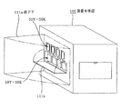
図3に示すように、装置本体部100の正面には、開閉自在な前ドア111aが配置されており、この前ドア111aを手前に開くと、各プロセスカートリッジ10および各トナー補給容器50を挿入する開口部が露出される。
【0092】
プロセスカートリッジ10を挿入する開口部には、回動可能に支持された芯決め板111bが配置されており、プロセスカートリッジ10を挿抜する場合は、この芯決め板111bを開放した後に行なう。
【0093】
図2に示すように、装置本体部100内には、各プロセスカートリッジ10の装着を案内するガイドレール120と、各トナー補給容器50の装着を案内するガイドレール121が固定されている。
【0094】
プロセスカートリッジ10およびトナー補給容器50の装着方向は、感光ドラム20の軸線方向と平行な方向であり、ガイドレール120、121も同様な方向に配置されている。プロセスカートリッジ10およびトナー補給容器50は、一旦、上記ガイドレール120、121に沿って装置本体部100内の手前から奥側にスライドされ挿入される。
【0095】
プロセスカートリッジ10が最奥部まで挿入されると、図4に示すように、ドラムフランジ22の中心穴22aに装置本体部100の芯決め軸122が挿入され、感光ドラム20の奥側の回転中心位置が装置本体部100に対して決められる。またこれと同時に、ドラムフランジ22に形成された駆動伝達部26と駆動カップリング112aが連結され、感光ドラム20の回転駆動が可能となる。
【0096】
駆動伝達部26はねじれた三角柱形状をなしており、装置本体部100からの駆動力が加わることで駆動が伝達されるとともに、感光ドラム20を奥側に引き込む力を発生させている。
【0097】
さらに、後側板130には、プロセスカートリッジ10を位置決めする支持ピン131が配置されており、この支持ピン131がプロセスカートリッジ10のフレームに挿入され、プロセスカートリッジ10のフレームの位置が固定される。
【0098】
装置本体部100の手前側には、前述のように、回動可能な芯決め板111bが配置されており、この芯決め板111bに対してプロセスカートリッジ10の軸受ケース23が支持固定される。これら一連の挿入動作により、感光ドラム20とプロセスカートリッジ10は装置本体部100に対して位置決めされる。
【0099】
一方、各トナー補給容器50は最奥部まで挿入されると、図5に示すように、後側板130から突出した支持ピン132に対して固定される。またこれと同時に、被駆動カップリング55と駆動カップリング112bが連結され、スクリュー51および撹拌軸53の回転駆動が可能となる。
【0100】
[プロセスカートリッジおよびトナー補給容器の結合構造]
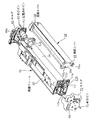
プロセスカートリッジ10は、図6に示すように、帯電装置30と、感光ドラム20を保持する現像装置40を含み、第1の枠体を構成するこれらの両端に、第2の枠体であるホルダ60、70を結合させてユニット化し、一体的なカートリッジとしたものである。
【0101】
図7および図10に示すように、帯電装置30の長手方向奥側の端部に取り付けられた端部カバー38には、位置決め用の円筒凸部38aと、位置決め穴である長穴38bが形成されており、長穴38bの壁面には被係止部である切欠き38cが形成されている。
【0102】
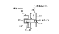
一方、図8および図12に示すように、長手方向手前側の端部カバー39には同様に丸穴39aと、位置決め穴である長穴39bが形成されており、長穴39bの壁面には被係止部である切欠き39cが形成されている。
【0103】
プロセスカートリッジ10の保持枠を構成する現像フレーム11の両端には、それぞれホルダ60、70を取り付けるためのフランジ11a、11bが形成されている。
【0104】
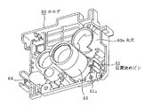
また、長手方向奥側のホルダ60には帯電装置30のための位置決め用の丸穴60aおよび位置決めピン61と、現像フレーム11への位置決め用の円筒凸部63および位置決めピン64が形成されている。
【0105】
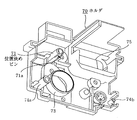
一方、手前側のホルダ70には、帯電装置30のための位置決め用の位置決めピン71、74a、現像フレーム11への位置決め用の円筒凸部73および位置決めピン74bが形成されている。さらにユーザーがプロセスカートリッジ10を引き出すための把手部75が形成されている。
【0106】
現像フレーム11の長手方向奥側フランジ11aには、ホルダ60に形成された、奥側位置決め用の円筒凸部63および位置決めピン64が通過できる穴11c、11dと、ホルダ60を現像フレーム11に位置決めるための丸穴1leおよび長穴1lfが形成されている。
【0107】
一方、手前側のフランジ11bには、ホルダ70に形成された、手前側の位置決めピン74a、74bが通過できる穴11g、11hと、ホルダ70を位置決めるための丸穴11iおよび長穴11jが形成されている。
【0108】
次にこれらの組み付け方法に関して説明する。
【0109】
まず現像フレーム11両端のフランジ11a、11bの間に、帯電装置30を組み込む。次に両端のフランジ11a、11bの外側より、ホルダ60、70をそれぞれ取り付ける。このとき奥側のホルダ60に形成された円筒凸部63および位置決めピン64が奥側のフランジ11aに形成された穴11c、11dにそれぞれ嵌合すると同時に、奥側のホルダ60に形成された丸穴60aおよび位置決めピン61が帯電装置30の端部カバー38に形成された円筒凸部38aおよび長穴38bにそれぞれ嵌合することで、現像フレーム奥側に対する、帯電装置30、ホルダ60の位置決めがなされる。
【0110】
同様に手前側のホルダ70に形成された円筒凸部73および位置決めピン74bが手前側のフランジ11bに形成された穴11iおよび穴11hにそれぞれ嵌合すると同時に、手前側のホルダ70に形成された位置決めピン71、74aが帯電装置30の端部カバー39に形成された丸穴39aおよび長穴39bにそれぞれ嵌合することで、現像フレーム手前側に対する、帯電装置30、ホルダ70の位置決めがなされる。
【0111】
次にホルダ60、70の結合方法について図10および図12を用いて説明する。
【0112】
奥側のホルダ60に形成された弾性係止手段(位置決め部材)である位置決めピン61は、中空円筒形状であり、その一部に爪61aが形成されている。この爪61aは、奥側の端部カバー38に形成された長穴38bに挿入される際、円筒部内側に撓み、挿入が完了すると、撓みが開放され前記長穴38bに形成された切欠き38cに係合する。
【0113】
同様に、手前側ホルダ70の中空円筒形状の弾性係止手段(位置決め部材)である位置決めピン71に形成された爪71aが、手前側の端部カバー39の長穴39bに形成された切欠き39cに係合する。
【0114】
すなわちこれらの爪61a、71aが帯電装置30に係合することで、結合が為される。
【0115】
結合がなされた後、位置決めピン61、71の嵌合部である中空部61b、71bに倒れ防止部材である結合ピン62、72を圧入する。結合ピン62、72は金属、樹脂成型品いずれでも良く、好ましくはホルダ60、70と同材質の樹脂とすることで、リサイクル性にも優れる。本参考例では、ポリスチレン樹脂を用いている。
【0116】
結合ピン62、72は、ホルダ60、70に形成された中空円筒形状の位置決めピン61、71に圧入されている訳であるが、これにより、一体的に強度を発揮することが可能となり、位置決めピンの倒れ強度を増すことができるという効果も得られる。
【0117】
また、結合ピン62、72の圧入による各位置決めピン61、71の変形量が、これを挿入する前の端部カバー38、39の長穴38b、39bとの間に予め設定された隙間寸法より大きくなるように設計しておくことで、ホルダ60、70を端部カバー38、39に対してより一層強固に固定できる。
【0118】
図13〜図15はトナー補給容器50をユニット化する結合構造を示すもので、第1の枠体であるトナー補給容器50には、ユーザーが着脱を容易にする把手81のついた、第2の枠体であるカバー部材80が取り付けられている。
【0119】
カバー部材80には、図15に示すようにトナー補給容器50に固定するための弾性係止手段である位置決め部82、83が形成されており、トナー補給容器50には、これらの先端に形成された爪82a、83aが係合する被係止部である穴50a、50bが形成されている。カバー部材80の各位置決め部82、83には、爪82a、83aの背面側に嵌合部である角穴84、85が形成されている。
【0120】
トナー補給容器50とカバー部材80が、前述した位置決め部82、83の爪82a、83aと穴50a、50bの係合により固定された後、角穴84、85とほぼ同形状の倒れ防止部材である結合部材86、87を挿入する。結合部材86、87には、カバー部材80に形成された爪82a、83aの反対側の面に爪部86a、87aを有しており、カバー部材80の角穴84、85に挿入されると、角穴先端の係合部84a、85aに結合部材87、87の爪部86a、87aが係合して、結合部材86、87が位置決め部82、83の角穴84、85内にしっかりと固定される。
【0121】
これにより、結合部材とカバー部材の角穴とが遊嵌の関係であっても、結合部材が抜け落ちることもなく、良好な結合強度を得ることができる。
【0122】
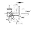
図16は本発明の一実施例を示すもので、位置決めピン71と同様の中空円筒形状の位置決めピン91の先端部に形成された爪91aの引掛け部には、爪足91bに対して挿入方向(嵌入方向)外向きに傾斜したテーパー部91cが設けられる。ここで爪91aの引掛け部は、端部カバー39の長穴39bに形成された切欠き39cに掛かった状態で若干撓んだ状態となるようにしている。この状態で嵌合部である中空部91dに倒れ防止部材である結合ピン92を圧入すると、爪91aの引っ掛け部には挿入方向への分力Py1 が発生し、嵌入方向への引き込み力が発生し、より一層安定した固定を行なうことができる。
【0123】
このように、爪形状を若干変更するだけで、部材間のガタ取りも可能となる。
【0124】
【発明の効果】
本発明は上述のとおり構成されているので、以下に記載するような効果を奏する。
【0125】
本発明は、弾性を利用したスナップフィットによる結合構造において、ガタ無くかつその結合力を強化し、組立作業性にも優れている、画像形成装置のプロセスカートリッジを提供することを実現できた。
【図面の簡単な説明】
【図1】 参考例による画像形成装置の全体構成を示す図である。
【図2】図1の装置のプロセスカートリッジとトナー補給容器を示す断面図である。
【図3】図1の画像形成装置の外観を示す概略斜視図である。
【図4】プロセスカートリッジを示す長手方向の断面図である。
【図5】トナー補給容器を示す長手方向の断面図である。
【図6】プロセスカートリッジの外観を示す斜視図である。
【図7】プロセスカートリッジを分解して示す分解斜視図である。
【図8】プロセスカートリッジを分解して逆方向からみた分解斜視図である。
【図9】一方のホルダの裏面を示す斜視図である。
【図10】図9のホルダの結合構造を示す部分断面図である。
【図11】他方のホルダの裏面を示す斜視図である。
【図12】図10のホルダの結合構造を示す部分断面図である。
【図13】トナー補給容器を示す斜視図である。
【図14】トナー補給容器を分解して示す分解斜視図である。
【図15】図14のカバー部材の結合構造を示す部分断面図である。
【図16】 本発明の一実施例による結合構造を示す部分断面図である。
【図17】従来例を説明する説明図である。
【符号の説明】
1、1Y、1M、1C、1K スキャナユニット
2 ポリゴンミラー
3 結像レンズ
4 反射ミラー
10、10Y、10M、10C、10K プロセスカートリッジ
11 現像フレーム
11a、11b フランジ
20 感光ドラム
21 ドラム軸
22 ドラムフランジ
23 軸受ケース
24 被駆動フランジ
25 軸受
26 駆動伝達部
30 帯電装置
31 帯電ローラ
32 芯金
33 帯電ローラクリーニング部材
37a 転写残トナー均一化手段
37b トナー帯電制御手段
38、39 端部カバー
38a、63、73 円筒凸部
39a 丸穴
38b、39b 長穴
38c、39c 切欠き
40 現像装置
41 現像スリーブ
42 マグネットローラ
43 規制ブレード
44 隔壁
45A、45B 撹拌スクリュー
46 センサー
50、50Y、50M、50C、50K トナー補給容器
50a、50b 穴
51 スクリュー
52 撹拌板
53 撹拌軸
55 被駆動カップリング
56 排出開口部
60、70 ホルダ
61、64、71、74a、74b、91 位置決めピン
61a、71a、82a、83a、91a 爪
61b、71b 中空部
62、72、92 結合ピン
75 把手部
80 カバー部材
81 把手
82、83 位置決め部
84、85 角穴
86、87 結合部材
86a、87a 爪部
91b 爪足
91c テーパー部
100 装置本体部
103a 給紙カセット
103b 給紙ローラ
103c リタードローラ
103d 給送ガイド
103e、103f 搬送ローラ
103g レジストローラ
104a 中間転写ベルト
104d 2次転写ローラ
104fY、104fM、104fC、104fK 転写帯電ローラ
105 クリーニングユニット
105a クリーニングブレード
106 定着器
106a 定着ローラ
106b 加圧ローラ
107 トナー
111a 前ドア
111b 芯決め板
112a、112b 駆動カップリング
120、121 ガイドレール
122 芯決め軸
130 後側板
131、132 支持ピン[0001]
BACKGROUND OF THE INVENTION
The present invention relates to a process cartridge mounted on an electrophotographic image forming apparatus such as an electrophotographic copying machine or an electrophotographic printer. of Using a snap-fit coupling structure as a means of integration The Process cartridge In It is related.
[0002]
Here, the electrophotographic image forming apparatus forms an image on a recording medium using an electrophotographic image forming process, and includes an electrophotographic copying machine, an electrophotographic printer (such as an LED printer and a laser beam printer), An electrophotographic facsimile machine and an electrophotographic word processor are included.
[0003]
In general, a process cartridge is a cartridge in which at least one of a charging unit, a developing unit, and a cleaning unit, which are process units, and an electrophotographic photosensitive member, which is an image carrier, are integrated into a cartridge. On the other hand, it is detachable. In the developing device, the developer accommodating portion and the developing means are integrated into a cartridge, and the cartridge can be attached to and detached from the image forming apparatus main body.
[0004]
[Prior art]
Conventionally, a process cartridge system has been adopted in which an electrophotographic photosensitive member of an electrophotographic image forming apparatus and a charging unit, a developing unit, a cleaning unit, etc. are integrated into a cartridge and the cartridge can be attached to and detached from the image forming apparatus main body. ing.
[0005]
The operability is further improved by this cartridge system, and the user can easily perform maintenance of the process means. Therefore, this cartridge system is widely used in the image forming apparatus main body.
[0006]
In addition, a cartridge configuration is realized in which the above-mentioned process means is divided into those having a long life and those having a short life, each process means is made into a cartridge, and can be used according to the life of the main process means. For example, a developing cartridge (developing unit) in which a developer container and a developing unit are integrally configured, or a drum cartridge (drum unit) in which an electrophotographic photosensitive member (photosensitive drum), a charging unit, and a cleaning unit are integrally configured. It has been adopted.
[0007]
[Problems to be solved by the invention]
In recent years, the demand for color image forming apparatuses capable of forming color images has increased.
(1) Low running cost
(2) Small space
(3) Low power
(4) High image quality
(5) High speed
(6) Improved operability
It is expected to introduce a color image forming apparatus that can achieve these six items.
[0008]
In the above items, there is a tendency that the number of added parts increases in order to improve the image quality. On the other hand, in order to reduce the running cost, a structure in which these parts can be easily assembled is required. One method for satisfying this requirement is a coupling structure by snap-fit using a so-called patch-on claw, in which a claw is hooked to a mating member using the elasticity of resin.
[0009]
This structure allows the part body and the locking claw to be integrally molded with resin and does not require a special tool for assembly work, so it can be reduced in cost, but the elasticity of the part body There was an unsolved problem that the nail would come off when a certain amount of load was applied. That is, as shown in FIG. 17, when a force P in the pulling direction is applied, a horizontal component force Px is generated due to the deformation of the resin, and thus the nail is detached. Although the above problem can be overcome to some extent by increasing the amount of nail application, it is easy to cause deterioration of assembly workability and plastic deformation of the nail part, and a fastening member such as a screw is used in combination with a portion requiring a strong connection. There was a need.
[0010]
The present invention has been made in view of the above-mentioned unsolved problems of the prior art, and is a coupling structure based on snap-fit utilizing elasticity. In the backlash Binding force The Strengthen And Excellent assembly workability , Image forming apparatus of Process cartridge The It is intended to provide.
[0011]
[Means for Solving the Problems]
In order to achieve the above object, the present invention Process cartridge Of image forming device In a process cartridge that is detachable from the apparatus main body and has a holder attached to an end cover, a slot provided in the end cover, a notch provided in the slot, and a positioning pin of the holder A claw formed at the tip of the claw, a hollow part formed on the back side of the claw, a taper part provided in the hooking part of the claw, and a coupling pin, A holder is attached to the end cover by fitting a positioning pin and press-fitting the coupling pin into the hollow portion in a state where the claw is bent and the taper portion is hooked on the notch. Combined It is characterized by this.
[0024]
[Action]
In a coupling structure with a snap fit in which the elastic locking means of one frame is elastically hooked and coupled to the locked portion of the other frame, a fitting for inserting a fall prevention member for strengthening the coupling force The joint portion is provided on the back side of the elastic locking means, the elastic locking means is hooked on the locked portion and the both frame bodies are assembled. Insert with the method.
[0025]
The fall-preventing member that is inserted presses the elastic locking means against the locked portion from the back side thereof, and strengthens the coupling force for preventing the dropout characteristic of the snap-fit structure.
[0026]
By greatly improving the coupling force in the snap-fit structure that is easy to assemble, a low-cost and highly reliable coupling structure can be realized.
[0028]
If the fall prevention member is made of the same material as at least one of the first and second frame bodies, the fall prevention member is easily compatible with the frame body and is low in cost.
[0029]
If the elastic locking means and the locked portion are constituted by a positioning member protruding from one of the first and second frames and a positioning hole provided in the other, positioning and assembly of the two frames Since it is performed simultaneously, it can contribute to simplification of the frame shape and assembly work.
[0030]
If the positioning member has a hollow portion and the fitting portion for fitting the fall prevention member is constituted by the hollow portion, the assembling work can be performed more easily and reliably.
[0031]
If the fall prevention member is press-fitted into the fitting portion, and the amount of deformation of the positioning member due to the press-fitting is larger than a preset gap dimension between the positioning member and the positioning hole, the fall prevention member is press-fitted. Thus, the positioning member expands in the positioning hole, so that the coupling force between the two is strengthened and the positioning member can be firmly fixed.
[0033]
DETAILED DESCRIPTION OF THE INVENTION
Embodiments of the present invention will be described with reference to the drawings.
[0034]
Figure 1 Reference example In the following description, the longitudinal direction is a direction orthogonal to the conveyance direction of the
[0035]
[Description of overall configuration]
The color image forming apparatus of FIG. 1 is a color laser beam printer, and its image forming unit is a
[0036]
Below the image forming section, a feeding means for feeding the
[0037]
Furthermore, fixing means for fixing the
[0038]
Here, the
[0039]
This image forming apparatus is an apparatus of a cleanerless system, and the transfer residual toner remaining on the photosensitive drum is taken into the developing means, and a dedicated cleaner for collecting and storing the transfer residual toner is not disposed in the process cartridge. .
[0040]
Next, the configuration of each part of the image forming apparatus will be sequentially described in detail.
[0041]
[Paper Feeder]
The paper feeding unit feeds the
[0042]
The
[0043]
Immediately after the
[0044]
During the image forming operation, the
[0045]
[Process cartridge]
The
[0046]
For example, the number of rotations of the
[0047]
The
[0048]
As shown in FIG. 4, a
[0049]
[Charging means]
The charging
[0050]
The charging roller cleaning member 33 has a flexible cleaning film 35. The cleaning film 35 is disposed in parallel with the longitudinal direction of the charging
[0051]
This image forming apparatus employs a cleanerless system. This cleanerless system will be described below.
[0052]
[Cleanerless system]
The outline of this cleanerless system will be described first. After the transfer, the untransferred toner on the
[0053]
Since the untransferred toner on the surface of the
[0054]
In addition, in order to effectively perform the simultaneous development cleaning of the transfer residual toner on the photosensitive drum surface by the developing
[0055]
In addition, along with the diversification of user needs in recent years, a large amount of residual toner is generated at a time due to continuous printing operations such as images with high printing ratios such as photographic images, further aggravating the problems described above. It will end up.
[0056]
Therefore, as shown in FIG. 2, a transfer residual toner (residual developer image) equalizing means 37a for equalizing the transfer residual toner on the
[0057]
By providing the transfer residual toner uniforming means 37a, even if the amount of toner remaining on the pattern on the photosensitive drum carried from the transfer portion d to the toner charge control means 37b is large, the toner remains on the photosensitive drum surface. Since the toner is distributed and non-patterned, the toner does not concentrate on a part of the toner
[0058]
The transfer residual toner uniformizing means 37a and the toner charge control means 37b are brush-like members having appropriate conductivity, and are arranged such that the brush portions are in contact with the photosensitive drum surface.
[0059]
These means move (reciprocate) in the longitudinal direction of the
[0060]
[Exposure means]
The exposure to the
[0061]
As shown in FIG. 1, the laser exposure means includes a solid laser element (not shown), a
[0062]
In this way, exposure in the main scanning direction by laser light scanning and exposure in the sub-scanning direction by rotating the
[0063]
[Development means]
The developing
[0064]
As shown in FIG. 4, the developing
[0065]
The toner used here is a negatively charged toner having an average particle diameter of 6 μm, and the magnetic carrier has a saturation magnetization of 205 emu / cm. Three A magnetic carrier having an average particle size of 35 μm was used. Further, a mixture of toner and carrier at a weight ratio of 6:94 is used as a developer.
[0066]
As shown in FIG. 2, the
[0067]
Here, a developing process for visualizing the electrostatic latent image formed on the
[0068]
As the developing
[0069]
In the process of being conveyed, the layer thickness of the developer is regulated by a
[0070]
The thin layer developer on the developing
[0071]
A direct current (DC) voltage and an alternating current (AC) voltage are applied to the developing
[0072]
In general, in the two-component development method, when an AC voltage is applied, the development efficiency is increased and the image becomes high quality, but there is also a risk that fog is likely to occur. For this reason, in general, it is possible to prevent fogging by providing a potential difference between the DC voltage applied to the developing
[0073]
When the toner is consumed by development, the toner concentration in the developer decreases. Therefore, a
[0074]
[Toner supply container]
The
[0075]
As shown in FIG. 2, a stirring
[0076]
The outer portion of the
[0077]
The tip end portion of the stirring
[0078]
[Transfer means]
The
[0079]
Further, in the
[0080]
The transfer charging rollers 104fY, 104fM, 104fC, and 104fK are supplied with power from a high-voltage power source (not shown), and are charged with the opposite polarity to the toner from the back side of the
[0081]
A
[0082]
Here, the
[0083]
At this time, the
[0084]
At a predetermined position of the
[0085]
In the
[0086]
The
[0087]
[Fixing part]
As shown in FIG. 1, the toner image formed on the
[0088]
The fixing
[0089]
That is, the
[0090]
[Installation of process cartridge and toner supply container]
Next, a procedure for mounting the
[0091]
As shown in FIG. 3, a front door 111a that can be opened and closed is arranged on the front surface of the apparatus
[0092]
A centering
[0093]
As shown in FIG. 2, a
[0094]
The mounting direction of the
[0095]
When the
[0096]
The
[0097]
Further, support pins 131 for positioning the
[0098]
As described above, the
[0099]
On the other hand, when each
[0100]
[Combination structure of process cartridge and toner supply container]
As shown in FIG. 6, the
[0101]
As shown in FIGS. 7 and 10, the
[0102]
On the other hand, as shown in FIGS. 8 and 12, the
[0103]
[0104]
The
[0105]
On the other hand, positioning pins 71 and 74a for positioning for the charging
[0106]
The developing
[0107]
On the other hand, the
[0108]
Next, these assembling methods will be described.
[0109]
First, the charging
[0110]
Similarly, the
[0111]
Next, a method for joining the
[0112]
The
[0113]
Similarly, a
[0114]
In other words, the
[0115]
After the coupling, the coupling pins 62 and 72 as the fall prevention members are press-fitted into the
[0116]
The coupling pins 62 and 72 are press-fitted into the hollow cylindrical positioning pins 61 and 71 formed in the
[0117]
Further, the amount of deformation of the positioning pins 61 and 71 due to the press-fitting of the coupling pins 62 and 72 is larger than the gap size set in advance between the
[0118]
FIGS. 13 to 15 show a coupling structure for unitizing the
[0119]
As shown in FIG. 15, the cover member 80 is formed with
[0120]
After the
[0121]
As a result, even when the coupling member and the square hole of the cover member are in a loose-fitting relationship, the coupling member does not fall out and good coupling strength can be obtained.
[0122]
FIG. Of the present invention one Implementation For example, the hooking portion of the
[0123]
As described above, it is possible to remove the play between the members only by slightly changing the nail shape.
[0124]
【The invention's effect】
Since this invention is comprised as mentioned above, there exists an effect as described below.
[0125]
The present invention utilizes elasticity Snap-fit connection structure In The binding power of strength And set For workability Also Excellent Providing a process cartridge for an image forming apparatus Can be realized The .
[Brief description of the drawings]
[Figure 1] Reference example 1 is a diagram illustrating an overall configuration of an image forming apparatus according to FIG.
FIG. 2 is a cross-sectional view showing a process cartridge and a toner supply container of the apparatus of FIG.
3 is a schematic perspective view showing an appearance of the image forming apparatus in FIG. 1. FIG.
FIG. 4 is a longitudinal sectional view showing a process cartridge.
FIG. 5 is a longitudinal sectional view showing a toner supply container.
FIG. 6 is a perspective view showing an appearance of a process cartridge.
FIG. 7 is an exploded perspective view showing the process cartridge in an exploded manner.
FIG. 8 is an exploded perspective view of the process cartridge as seen from the opposite direction.
FIG. 9 is a perspective view showing a back surface of one holder.
10 is a partial cross-sectional view showing a coupling structure of the holder of FIG. 9;
FIG. 11 is a perspective view showing the back surface of the other holder.
12 is a partial cross-sectional view showing a coupling structure of the holder of FIG.
FIG. 13 is a perspective view showing a toner supply container.
FIG. 14 is an exploded perspective view showing the toner supply container in an exploded manner.
15 is a partial cross-sectional view showing the cover member coupling structure of FIG. 14;
FIG. 16 Of the present invention one Implementation It is a fragmentary sectional view which shows the coupling structure by an example.
FIG. 17 is an explanatory diagram illustrating a conventional example.
[Explanation of symbols]
1, 1Y, 1M, 1C, 1K Scanner unit
2 Polygon mirror
3 Imaging lens
4 Reflection mirror
10, 10Y, 10M, 10C, 10K Process cartridge
11 Development frame
11a, 11b Flange
20 Photosensitive drum
21 Drum shaft
22 Drum flange
23 Bearing case
24 Driven flange
25 Bearing
26 Drive transmission part
30 Charging device
31 Charging roller
32 cored bar
33 Charging roller cleaning member
37a Transfer residual toner uniformizing means
37b Toner charging control means
38, 39 End cover
38a, 63, 73 Cylindrical convex part
39a round hole
38b, 39b oblong hole
38c, 39c Notch
40 Developer
41 Development sleeve
42 Magnet roller
43 Regulating blade
44 Bulkhead
45A, 45B stirring screw
46 sensors
50, 50Y, 50M, 50C, 50K Toner supply container
50a, 50b hole
51 screw
52 Stirring plate
53 Stirring shaft
55 Driven coupling
56 Discharge opening
60, 70 holder
61, 64, 71, 74a, 74b, 91 Positioning pin
61a, 71a, 82a, 83a, 91a Nail
61b, 71b Hollow part
62, 72, 92 Connecting pin
75 Handle part
80 Cover member
81 Handle
82, 83 Positioning part
84, 85 square holes
86, 87 coupling member
86a, 87a Nail
91b Claw feet
91c taper part
100 Device body
103a Paper cassette
103b Paper feed roller
103c retard roller
103d Feeding guide
103e, 103f Conveying roller
103g Registration roller
104a Intermediate transfer belt
104d Secondary transfer roller
104fY, 104fM, 104fC, 104fK Transfer charging roller
105 Cleaning unit
105a Cleaning blade
106 Fixing device
106a Fixing roller
106b Pressure roller
107 Toner
111a Front door
111b Centering plate
112a, 112b Drive coupling
120, 121 guide rail
122 Centering axis
130 Rear side plate
131, 132 Support pin
Claims (1)
前記端部カバーに設けられた長穴と、前記長穴に設けられた切欠きと、
前記ホルダの有する位置決めピンの先端に形成された爪と、前記爪の背面側に形成された中空部と、前記爪の引掛け部に設けられたテ−パ部と、
結合ピンと、
を有し、
前記長穴に前記位置決めピンを嵌合して、前記爪が撓んだ状態で前記テ−パ部が前記切欠きに掛かった状態で、前記中空部に前記結合ピンを圧入することによって、端部カバーにホルダを結合したプロセスカートリッジ。 A detachable to the apparatus main body of the images forming apparatus, the process cartridge that combines the holder to an end cover,
A slot provided in the end cover, a notch provided in the slot,
A claw formed at the tip of the positioning pin of the holder, a hollow part formed on the back side of the claw, a taper part provided in the hooking part of the claw,
A coupling pin;
Have
By fitting the positioning pin into the elongated hole, and press-fitting the coupling pin into the hollow portion in a state where the claw is bent and the taper portion is hooked on the notch, A process cartridge with a holder attached to the cover .
Priority Applications (1)
| Application Number | Priority Date | Filing Date | Title |
|---|---|---|---|
| JP2001399333A JP3890230B2 (en) | 2001-12-28 | 2001-12-28 | Process cartridge |
Applications Claiming Priority (1)
| Application Number | Priority Date | Filing Date | Title |
|---|---|---|---|
| JP2001399333A JP3890230B2 (en) | 2001-12-28 | 2001-12-28 | Process cartridge |
Publications (3)
| Publication Number | Publication Date |
|---|---|
| JP2003195727A JP2003195727A (en) | 2003-07-09 |
| JP2003195727A5 JP2003195727A5 (en) | 2004-10-28 |
| JP3890230B2 true JP3890230B2 (en) | 2007-03-07 |
Family
ID=27604414
Family Applications (1)
| Application Number | Title | Priority Date | Filing Date |
|---|---|---|---|
| JP2001399333A Expired - Fee Related JP3890230B2 (en) | 2001-12-28 | 2001-12-28 | Process cartridge |
Country Status (1)
| Country | Link |
|---|---|
| JP (1) | JP3890230B2 (en) |
Families Citing this family (9)
| Publication number | Priority date | Publication date | Assignee | Title |
|---|---|---|---|---|
| JP4556452B2 (en) * | 2004-03-11 | 2010-10-06 | 富士ゼロックス株式会社 | Developing device and image forming apparatus |
| EP1630622A3 (en) | 2004-08-30 | 2006-09-06 | Seiko Epson Corporation | Developing device, image forming apparatus, and image forming system |
| US7680433B2 (en) * | 2004-12-08 | 2010-03-16 | Fuji Xerox Co., Ltd. | Process cartridge with casings combined by coupling pin, and assembling method and disassembling method thereof |
| EP1842108A1 (en) * | 2005-01-25 | 2007-10-10 | GCC IP Pty Limited | Two-part process cartridge and its assembly/disassembly |
| JP5299686B2 (en) * | 2008-08-08 | 2013-09-25 | 株式会社リコー | Process cartridge and image forming apparatus |
| JP5264693B2 (en) * | 2009-02-27 | 2013-08-14 | キヤノン株式会社 | Cleaning device, developing device, cartridge, cleaning blade fixing method, developing blade fixing method |
| JP5045766B2 (en) | 2010-01-22 | 2012-10-10 | ブラザー工業株式会社 | Image forming apparatus |
| JP7147382B2 (en) * | 2018-09-03 | 2022-10-05 | 富士フイルムビジネスイノベーション株式会社 | Snap-fit coupling structure and image forming apparatus |
| JP7494069B2 (en) | 2020-09-16 | 2024-06-03 | キヤノン株式会社 | Cartridge and method for disassembling cartridge |
-
2001
- 2001-12-28 JP JP2001399333A patent/JP3890230B2/en not_active Expired - Fee Related
Also Published As
| Publication number | Publication date |
|---|---|
| JP2003195727A (en) | 2003-07-09 |
Similar Documents
| Publication | Publication Date | Title |
|---|---|---|
| JP4072362B2 (en) | Developing device, process cartridge, and image forming apparatus | |
| JP4314006B2 (en) | Image forming apparatus | |
| JP3432218B2 (en) | Process cartridge, load generating member, and electrophotographic image forming apparatus | |
| JP3913153B2 (en) | Power supply contact member, process cartridge, and image forming apparatus | |
| JP2003215917A (en) | Developing device, process cartridge and image forming apparatus | |
| JP2004151563A (en) | Recycling method for process cartridge | |
| JP3890227B2 (en) | Process means moving mechanism, charging device, process cartridge, and electrophotographic image forming apparatus | |
| JP2002268356A (en) | Shutter device, developer replenishing container, developing cartridge, process cartridge, developer replenishing container and developing cartridge, the developer replenishing container and process cartridge, and electrophotographic image forming device | |
| JP2004101690A (en) | Development device, process cartridge, and electrophotographic image forming apparatus | |
| JP2002006601A (en) | Developer replenishing container and image forming device | |
| JP3890230B2 (en) | Process cartridge | |
| JP4886127B2 (en) | Cartridge and electrophotographic image forming apparatus | |
| JP2002296884A (en) | Developer carrying member, developer replenishing container and image forming device | |
| JP3913006B2 (en) | Electrophotographic image forming apparatus | |
| JP3919516B2 (en) | Toner processing device, process cartridge, and image forming apparatus | |
| JP2004077758A (en) | Developing device and processing cartridge | |
| JP4666848B2 (en) | Image forming apparatus | |
| JP3943929B2 (en) | Process means support mechanism, charging device, process cartridge, and electrophotographic image forming apparatus | |
| JP4669148B2 (en) | Developing device, process cartridge, and image forming apparatus | |
| JP2004126002A (en) | Protective member, process cartridge, developing apparatus and image forming apparatus | |
| JP2004126182A (en) | Joint structure, development device, and process cartridge | |
| JP2004078006A (en) | Developing device, electrifying device and process cartridge | |
| JP3774657B2 (en) | Charging device, process cartridge, and image forming apparatus using the same | |
| JP2002006607A (en) | Toner cap, toner housing container and process cartridge | |
| JP2002296903A (en) | Gap retaining member, process cartridge and image forming device |
Legal Events
| Date | Code | Title | Description |
|---|---|---|---|
| A977 | Report on retrieval |
Free format text: JAPANESE INTERMEDIATE CODE: A971007 Effective date: 20050830 |
|
| A131 | Notification of reasons for refusal |
Free format text: JAPANESE INTERMEDIATE CODE: A131 Effective date: 20060620 |
|
| A521 | Written amendment |
Free format text: JAPANESE INTERMEDIATE CODE: A523 Effective date: 20060810 |
|
| TRDD | Decision of grant or rejection written | ||
| A01 | Written decision to grant a patent or to grant a registration (utility model) |
Free format text: JAPANESE INTERMEDIATE CODE: A01 Effective date: 20061122 |
|
| A61 | First payment of annual fees (during grant procedure) |
Free format text: JAPANESE INTERMEDIATE CODE: A61 Effective date: 20061204 |
|
| R150 | Certificate of patent or registration of utility model |
Free format text: JAPANESE INTERMEDIATE CODE: R150 |
|
| FPAY | Renewal fee payment (event date is renewal date of database) |
Free format text: PAYMENT UNTIL: 20091208 Year of fee payment: 3 |
|
| FPAY | Renewal fee payment (event date is renewal date of database) |
Free format text: PAYMENT UNTIL: 20101208 Year of fee payment: 4 |
|
| FPAY | Renewal fee payment (event date is renewal date of database) |
Free format text: PAYMENT UNTIL: 20111208 Year of fee payment: 5 |
|
| FPAY | Renewal fee payment (event date is renewal date of database) |
Free format text: PAYMENT UNTIL: 20121208 Year of fee payment: 6 |
|
| FPAY | Renewal fee payment (event date is renewal date of database) |
Free format text: PAYMENT UNTIL: 20131208 Year of fee payment: 7 |
|
| LAPS | Cancellation because of no payment of annual fees |