JP3889885B2 - Millimeter-wave transmitter, millimeter-wave receiver, millimeter-wave transmission / reception system, and electronic device - Google Patents
Millimeter-wave transmitter, millimeter-wave receiver, millimeter-wave transmission / reception system, and electronic device Download PDFInfo
- Publication number
- JP3889885B2 JP3889885B2 JP23294998A JP23294998A JP3889885B2 JP 3889885 B2 JP3889885 B2 JP 3889885B2 JP 23294998 A JP23294998 A JP 23294998A JP 23294998 A JP23294998 A JP 23294998A JP 3889885 B2 JP3889885 B2 JP 3889885B2
- Authority
- JP
- Japan
- Prior art keywords
- millimeter wave
- wave
- frequency
- millimeter
- broadcast
- Prior art date
- Legal status (The legal status is an assumption and is not a legal conclusion. Google has not performed a legal analysis and makes no representation as to the accuracy of the status listed.)
- Expired - Fee Related
Links
Images


Classifications
-
- H—ELECTRICITY
- H04—ELECTRIC COMMUNICATION TECHNIQUE
- H04H—BROADCAST COMMUNICATION
- H04H40/00—Arrangements specially adapted for receiving broadcast information
- H04H40/18—Arrangements characterised by circuits or components specially adapted for receiving
- H04H40/27—Arrangements characterised by circuits or components specially adapted for receiving specially adapted for broadcast systems covered by groups H04H20/53 - H04H20/95
- H04H40/90—Arrangements characterised by circuits or components specially adapted for receiving specially adapted for broadcast systems covered by groups H04H20/53 - H04H20/95 specially adapted for satellite broadcast receiving
-
- H—ELECTRICITY
- H04—ELECTRIC COMMUNICATION TECHNIQUE
- H04H—BROADCAST COMMUNICATION
- H04H20/00—Arrangements for broadcast or for distribution combined with broadcast
- H04H20/53—Arrangements specially adapted for specific applications, e.g. for traffic information or for mobile receivers
- H04H20/61—Arrangements specially adapted for specific applications, e.g. for traffic information or for mobile receivers for local area broadcast, e.g. instore broadcast
- H04H20/63—Arrangements specially adapted for specific applications, e.g. for traffic information or for mobile receivers for local area broadcast, e.g. instore broadcast to plural spots in a confined site, e.g. MATV [Master Antenna Television]
-
- H—ELECTRICITY
- H04—ELECTRIC COMMUNICATION TECHNIQUE
- H04H—BROADCAST COMMUNICATION
- H04H60/00—Arrangements for broadcast applications with a direct linking to broadcast information or broadcast space-time; Broadcast-related systems
- H04H60/76—Arrangements characterised by transmission systems other than for broadcast, e.g. the Internet
- H04H60/81—Arrangements characterised by transmission systems other than for broadcast, e.g. the Internet characterised by the transmission system itself
- H04H60/90—Wireless transmission systems
-
- H—ELECTRICITY
- H04—ELECTRIC COMMUNICATION TECHNIQUE
- H04N—PICTORIAL COMMUNICATION, e.g. TELEVISION
- H04N7/00—Television systems
- H04N7/10—Adaptations for transmission by electrical cable
- H04N7/106—Adaptations for transmission by electrical cable for domestic distribution
-
- H—ELECTRICITY
- H04—ELECTRIC COMMUNICATION TECHNIQUE
- H04N—PICTORIAL COMMUNICATION, e.g. TELEVISION
- H04N7/00—Television systems
- H04N7/20—Adaptations for transmission via a GHz frequency band, e.g. via satellite
Description
【0001】
【発明の属する技術分野】
本発明は、VHF、UHF等の地上放送やBS、CS等の衛星放送などの複数の放送波を屋内においてミリ波で無線伝送するためのミリ波送信装置、ミリ波受信装置、ミリ波送受信システム及び電子機器に関する。
【0002】
【従来の技術】
地上放送(VHF、UHF)、衛星放送(BS、CS)等の複数の放送が実現されている。今までの個人住宅におけるTV放送受信システムを図10に示す。衛星放送の場合、12GHz帯の信号をBSアンテナ1、CSアンテナ2で夫々受信し、夫々のアンテナの直近に低雑音コンバータ3が取り付けられ、1〜2GHz帯の中間周波数帯に変換された後、それぞれ同軸ケーブル4、5で屋外から室内のTV受信機6(BS・CSチューナ又はBS・CSチューナ内蔵のTV)に配線されていた。また、地上放送は、UHFアンテナ7、VHFアンテナ8の無線周波数帯の信号を混合した後(またはそれぞれ独立に)、同軸ケーブル9で各室内のTV受信機6まで有線で配線されていた。
【0003】
一方、集合住宅等でのTV放送受信システムを図11に示す。図11に示すように、衛星放送は、共同受信用BSアンテナ11、共同受信用CSアンテナ12で夫々受信し、1〜2GHz帯の中間周波数帯に変換された後、ブロックコンバータ13で、CS信号を周波数変換した後、地上波放送のVHF・UHF信号と衛星放送BS・CS信号とは混合され、一本の同軸ケーブル14で配線され、分配器15、増幅器16を経由して、各家庭、各室内まで有線で配線されていた。
【0004】
【発明が解決しようとする課題】
しかしながら、個人住宅においては、複数のTV受信機に伝送する場合には配線が複雑になっていた。一方、集合住宅の場合においては、各家庭まで一本の同軸ケーブル14にすべての放送波が乗せられているものの、予め分配器を設定するため取り付けられるTV受信機の台数には限りがあり、TV受信機の増設の場合には、別途新たな分配器を設置するなどの工事が必要になっていた。
【0005】
本発明の目的は、複雑な配線を無くし、衛星放送(BS、CS)、及び地上波放送(VHF、UHF)を屋内でミリ波無線伝送するためのミリ波送受信システムを提供することにある。また、上記のミリ波送受信システムを実現するためのミリ波送信装置、ミリ波受信装置を提供することにある。
【0006】
【課題を解決するための手段】
本発明のミリ波送信装置では、複数の放送波を入力する手段と、前記複数の放送波のうちの地上放送波を地上波周波数帯以外の周波数帯であってミリ波局部発振器の局部発振波の近傍でない周波数帯の周波数軸上に配列する周波数配列手段と、前記複数の放送波をミリ波にアップコンバートする手段と、前記ミリ波から前記ミリ波局部発振器の局部発振波を除去する手段と、前記局部発振波が除去された前記ミリ波を送信する手段と、から構成される。本構成により地上放送、衛星放送などの放送波を配線を引くことなく、各部屋に送信することができる。
【0007】
本発明では屋内の無線伝送として60GHz帯(通常59GHz〜64GHz)のミリ波を用いた。60GHz帯のミリ波は、現在の衛星、地上TV放送波に比較して、著しく周波数が高く、使用できる帯域幅が広いため、地上放送、衛星放送をまとめて一度に無線伝送すること可能である。加えて、酸素・水分による吸収が大きいため、隣接した家との間での遮蔽が容易という特徴が有り、各家庭の屋内での無線伝送には適している。
【0008】
請求項1乃至4のいずれかに記載のミリ波送信装置は、前記ミリ波にアップコンバートする手段の前に、前記複数の放送波の出力レベルを一定にするための増幅器を有することを特徴とする。
【0009】
請求項1乃至4のいずれかに記載のミリ波送信装置は、前記ミリ波にアップコンバートする手段の前に、周波数高域側の前記放送波の出力レベルを周波数低域側よりも大きくするための増幅器を有することを特徴とする。
【0010】
請求項1乃至4のいずれかに記載のミリ波送信装置は、前記ミリ波にアップコンバートする手段の前に、前記複数の放送波のうち他の放送波と比較してC/Nを必要とする放送波の出力レベルを選択的に高めるための増幅器を有することを特徴とする。
【0011】
また、前記ミリ波送信装置には、TV受信機の偏波制御信号を変換した赤外線信号を受信し、偏波制御信号に再生する手段を備える。
【0012】
また、前記ミリ波送信装置には、TV受信機の偏波制御信号を変換したUHF無線信号を受信・復調し、偏波制御信号に再生する手段を有する。
【0013】
また、前記ミリ波送信装置には、UHF帯無線部の局部発振部を用いて、前記アップコンバートする手段に用いる局部発振部の同期をとる手段を備える。
【0014】
本発明のミリ波受信装置では、請求項1に記載のミリ波送信装置から送信されたミリ波を受信する手段と、前記ミリ波を放送波の周波数帯にダウンコンバートする手段と、該ダウンコンバートされた複数の放送波のうちの地上放送波を地上波周波数に変換する周波数逆配列手段と、から構成されることを特徴とする。
【0015】
また、前記ミリ波受信装置には、TV受信機の偏波制御信号を赤外線信号として送信する手段を備える。
【0016】
また、前記ミリ波受信装置には、TV受信機の偏波制御信号をUHF無線信号に変調・送信する手段を有する。
【0017】
また、前記ミリ波受信装置には、UHF帯無線部の局部発振部を用いて、前記ダウンコンバートする手段に用いる局部発振部の同期をとる手段を備える。
【0018】
さらに、上記ミリ波受信装置と上記ミリ波送信装置を有したミリ波送受信システムを提供する。
【0019】
また、上記ミリ波送信装置と、上記ミリ波受信装置との少なくともいずれか1つを備えた電子機器を提供する。
【0020】
【発明の実施の形態】
(実施の形態1)
屋内の無線システムとして60GHz帯のミリ波を用いた。60GHz帯のミリ波は、現在の衛星、地上TV放送波に比較して、著しく周波数が高く、送受信機の無線帯域幅が広くとれるため、地上放送、衛星放送をまとめて一度に無線伝送すること可能である。加えて、この周波数帯では、酸素・水分による吸収が大きいため、隣接した家との間での遮蔽が容易である。さらにこの周波数帯では、1/2波長が、空気中で2.5mmで、ICのチップサイズの大きさと同程度であり、アンテナを含めてICと一体化できる。そのため、機器が小さくなるという特徴が有り、軽量で小型の無線モジュールが電子機器に組み込めることから、家庭内での屋内無線伝送には適した周波数帯である。
【0021】
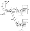
図1は、集合住宅の場合の本発明の屋内ミリ波無線伝送TV受信システムを説明する図である。従来例を示す図10、図11と同一・同義の部分は、同じ記号を用いた。符号20はミリ波送信装置、21はミリ波受信装置である。一つのミリ波送信装置20から、複数のミリ波受信装置21(本実施の形態では3台のミリ波受信装置21)で受信する構成について示している。ミリ波送信装置20には、複数のTV放送波を周波数軸上に並べる周波数変換器(以下、周波数配列器22と呼ぶ)、中間周波数帯からミリ波帯の無線信号に変換するアップコンバータ23、アンテナ25から構成される。一方ミリ波受信装置21は、アンテナ25、ミリ波帯無線信号から中間周波数帯へ変換するダウンコンバータ24、周波数軸上に並んだ中間周波数帯から通常のTV放送波へ変換する周波数変器(以下、周波数逆配列器26と呼ぶ)から構成される。
【0022】
図2に、ミリ波無線伝送TV受信システム中の周波数配列器の構成を示す。図3に、本実施の形態におけるミリ波無線伝送TV受信システムを用いた場合の周波数配列を示す。図3(a)に示すように、周波数配列器22に入力された入力信号におけるCS及びBSの中間周波数は、すでにブロックコンバータ13により、中間周波数1035MHz〜1895MHzの周波数軸上に配列されている。このような入力信号を図2(a)に示す周波数配列器22により、地上波放送のみを、周波数ミキサ31と局部発振器32により、周波数変換し、周波数軸上に配列させる。この時出力される信号の周波数配列では図3(b)に示すように地上波放送を周波数変換している。これは、地上波放送の周波数が低いので、60GHz帯へアップコンバートされた信号は、局部発振波の近傍にくるが、本来この局部発振波は、アンテナ25からは放射されることなく除去されなければならない不要波であるため、地上波放送は、そのままアップコンバートすると局部発振波とともに、除去されてしまう。そのため、地上放送波は、一旦中間周波数段階で、他の周波数帯(例えば、2GHz帯)へ周波数配列器22で周波数変換される。
【0023】
このように周波数軸上に配列された放送波は、ミリ波送信装置20中のアップコンバータ23で60GHz帯にアップコンバートされ、図3(c)に示すような無線周波数となり、ミリ波送信装置20のアンテナ25からミリ波無線信号として出力される。
【0024】
一方、ミリ波受信装置21のアンテナ25でミリ波無線信号を受信し、ダウンコンバートされた放送波は、周波数逆配列器26へ入力される。周波数逆配列器26は、図2(b)に示すように、周波数配列器22とは、逆の過程であり、周波数ミキサ31と局部発振器32により、周波数軸上に並んだ中間周波数から本来の地上波周波数へ周波数変換する機能を有している。この周波数逆配列器26の出力の周波数関係を図3(d)に示している。このようにして得られた放送波をTV受信機6に入力してTV受信を可能とした。
【0025】
(実施の形態2)
図4は、個人住宅の場合の屋内ミリ波無線伝送TV受信システムを説明する図である。また、図5に、実施の形態2におけるミリ波無線伝送TV受信システム中の周波数配列器の構成を示す。図6に、本実施の形態2におけるミリ波無線伝送TV受信システムを用いた場合の周波数配列を示す。図1と同一・同義の部分は同じ記号を用いた。異なる部分についてのみ説明する。一つのミリ波送信装置20から、複数のミリ波受信装置21(本実施例では2台のミリ波受信装置21)で受信する構成について示しており、ミリ波送信装置20、ミリ波受信装置21の基本構成は第1の実施例を示す図1と同様であるが、第1の実施例と比較して、ミリ波送信装置、ミリ波受信装置は、周波数配列器22と周波数逆配列器26の構成と、赤外線送信装置40、赤外線受信装置41を有している点が異なる。
【0026】
これは、ブロックコンバータ13を用いないような個人住宅用の場合には、周波数配列器22への入力信号は、BS信号、CS信号、地上波信号は独立の3本同軸ケーブルから入力される構成になり、BSの中間周波数成分(1035MHz〜1335MHz)とCSの中間周波数成分(1293MHz〜1548MHz)は、一部重なっており、かつ、CS信号は、垂直偏波成分と水平偏波成分を有し、CSアンテナ2で、CSチューナから出力されるDC制御バイアスで、番組選局に応じて切り替えられる。
【0027】
図6(a)に示すように、ブロックコンバータを用いていない場合のCS放送波の周波数成分は重なった周波数成分となっている。具体的には、TV受信機6のCSチューナからの選局により、DC制御バイアス11Vまたは15Vを発生し、CSアンテナ2から、受信偏波成分(垂直偏波11V、水平偏波15V)を切り替えることで、所望の偏波成分を取り出し構成になっている。従って、個人住宅用のミリ波送信装置20中の周波数配列器22の構成は、図5(a)に示すようであり、周波数配列器22は、地上波放送の中間周波数とCS放送の中間周波数を、周波数ミキサ42と局部発振器43により周波数変換し、周波数軸上に配列させる。周波数変換した周波数配列を図6(b)に示す。図6(b)に示すように、BS放送の中間周波数と変換後のCS放送の周波数との重なりをなくし、地上波放送の中間周波数を他の周波数帯(例えば2GHz帯)に一旦変換している。
【0028】
一方、ミリ波受信装置21中の周波数逆配列器26は、この逆の過程であり、周波数ミキサ42と局部発振器43により、周波数軸上に並んだ中間周波数から本来の地上波周波数、CS放送波の中間周波数帯へ周波数変換する機能を有している。このようにして変換した周波数配列を図6(c)に示す。周波数逆配列器26を用いることによって、放送波は元の周波数配列に戻している。
【0029】
加えて、個人住宅用のCSアンテナ2から入力されるCS放送の垂直・水平偏波成分は、選局によって垂直偏波(11V)/垂直偏波(15V)とを選択した偏波制御信号であるDC制御バイアス44によって切り替える必要がある。従って、TV受信機6のCSチューナからのDC制御バイアス44が赤外線送信装置40に入力され、入力されたDC制御バイアス44を信号処理部45により変調信号を生成し、電気/光変換器46により赤外線信号がワイアレスで赤外線送信装置40から送信される。ミリ波送信装置20中の赤外線受信装置41で、電気/光変換器46により、電気信号を取り出し、信号処理部45で、再び、垂直・水平偏波制御のためのDC制御バイアス44を生成する。このようにして、CS放送の垂直/水平偏波の切り替えを行う。
【0030】
(実施の形態3)
図7は、個人住宅の場合の第2の屋内ミリ波無線伝送TV受信システムを説明する図である。実施の形態2を示す図4と同一・同義の部分は同じ記号を用いた。異なる部分についてのみ説明する。一つのミリ波送信装置20から、複数のミリ波受信装置21(本実施例では2台のミリ波受信装置21)で受信する構成について図7には示している。ミリ波送信装置、ミリ波受信装置の基本構成は実施の形態2を示す図4と同様であるが、垂直・水平偏波成分切り替えのための偏波制御信号であるDC制御バイアスを変換した赤外線信号のかわりにUHF帯の電波信号を使用し、ミリ波送信装置20にはUHF帯無線受信装置51、ミリ波受信装置21にはUHF帯無線送信装置50を備えている点である。このUHF帯の電波信号は、現在のISM帯(2.4GHz帯)の周波数帯や、PHS等のコードレス電話の周波数帯として使われており、部品等、小型かつ安価であるため、UHF帯を利用するのが望ましい。またこれは、VHF帯の微弱電波を用いても構わない。
【0031】
このUHF帯無線送信装置50は、TV受信機6中のCSチューナからのDC制御バイアス44を、信号処理し変調波を生成する信号処理部45、変調波をUHF帯無線信号に変換するUHF帯無線部52から構成される。一方、UHF帯無線受信装置51は、UHF帯無線信号を復調波変換するUHF帯無線部53、及び、復調波からTV受信機6中のCSチューナのDC制御バイアス44を再生成する信号処理部45から構成される。
【0032】
特に、UHF帯の電波を用いることによって、赤外線での通信とは異なり、襖、壁等の遮蔽物を透過できるため、ミリ波送信装置、ミリ波受信装置は仕切られた部屋と部屋間でも使うことができる。さらに、PHS等のコードレス電話を組み込むことにより、水平・垂直偏波制御のための信号だけでなく、データ伝送も可能となり、双方向の通信が可能となるメリットがある。
【0033】
(実施の形態4)
図8は、個人住宅の場合の第3の屋内ミリ波無線伝送TV受信システムを説明する図である。実施の形態3を示す図7と同一・同義の部分は同じ記号を用いた。異なる部分についてのみ説明する。ミリ波送信装置、ミリ波受信装置の基本構成は実施の形態3を示す図7と同様であり、垂直・水平偏波成分を切り替えのための制御信号を、UHF帯のUHF帯無線送信装置50、UHF帯無線受信装置51を使用する点までは同じである。本実施の形態においては、ミリ波送信装置20及びミリ波受信装置21を安定動作させるために、UHF帯無線部52、53の基準信号を利用して、ミリ波送信装置20及びミリ波受信装置21の局部発振信号の安定化と低雑音化する点にある。
【0034】
図9に本実施の形態で用いたミリ波送信装置20及びミリ波受信装置21の構成の一部を示す。図5と同一・同義の部分は同じ記号を用いた。ミリ波送信装置のUHF帯無線部52、53のUHF帯局部発振器61は水晶発振器62で駆動される位相同期発振器回路から構成される。UHF帯局部発振器61からの信号をアップコンバータ23中の高調波増幅器63ヘ導き、高調波増幅器63はUHF帯局部発振器61からの信号の高調波成分を生成し、ミリ波局部発振器64へ注入することによって、ミリ波局部発振器64を同期する構成である。ミリ波受信装置においても同様の構成である。
【0035】
本実施の形態の構成例では、ミリ波局部発振器64への注入同期方式を用いたが、UHF帯局部発振器61(またはUHF帯局部発振器61中の水晶発振器62)とミリ波ハーモニックミキサ、位相比較器、周波数分周器、ループフィルタ等を用いて、ミリ波局部発振器64に位相同期をかけても良い。ミリ波局部発振器64から生成されるミリ波信号は、雑音成分が少なく、水晶発振器のレベルと同等の周波数安定性が得ることが可能となる。
【0036】
(実施の形態5)
図12は、ミリ波送信装置の別の実施の形態を示す図である。図12(a)は、集合住宅の場合におけるブロックコンバータを利用した時の構成図である。一方、図12(b)は、個人住宅の場合における構成図である。その構成は、IF出力レベル調整用アンプ90、周波数配列器91、周波数補償用IFアンプ92、ミリ波アップコンバータ93からなる。尚、図12ではIF出力レベル側調整用アンプ90の入力部にa、周波数配列器の入力部にb、ミリ波アップコンバータの入力部にcの記号を付す。集合住宅の場合におけるブロックコンバータを使用した時には、一本の同軸ケーブル上に信号があるため、直列に各周波数帯域毎に増幅を行い、出力信号レベルを調整するようにしたものであり、個人住宅の場合では、複数本のケーブル上に各放送波信号が分配されているので、並列に各周波数毎に増幅される構成である。
【0037】
図13では、各入力部(a,b,c)での信号レベルを示す。図13を用いて本実施の形態に示すミリ波送信装置の構成の動作について説明する。入力された地上波、BS波、CS波などの放送波はIF出力レベル側調整用アンプに入力される。入力部aでの信号レベルは図13(a)のようであり、放送波の種類ごとに出力レベルが異なっている。IF出力レベル側調整用アンプでは、各種の放送波によって、または、受信地域や使用するアンテナの利得によって異なるため、それぞれの放送波の受信帯域で異なった利得を有する増幅を行い、出力レベルを一定にする。このようにして一定の出力レベルにされた入力部bでの信号レベルを図13(b)に示す。さらに、ミリ波アップコンバータの入力部前段では周波数補償用IFアンプが設けられている。周波数補償用IFアンプは、ミリ波帯にアップコンバートした際、ミリ波帯の高域側ではミリ波帯アップコンバートの利得やミリ波受信機の利得が、低域側に比較して小さいので、予めIF周波数の時点で高域側の信号レベルを強調(高出力)にすることによって、ミリ波無線伝送時の周波数高域側の伝送損失を補償することができ、安定した広帯域のミリ波無線伝送を確保することができる。このようにして周波数広域側の出力レベルを高出力とした入力部cでの信号レベルを図13(c)に示す。
【0038】
尚、本実施例では、周波数補償用IFアンプを有する構成としたが、周波数補償用IFアンプは必ずしも必要なものではなく、出力レベル側調整用アンプの出力をミリ波アップコンバータに入力しても効果は十分に発揮するものである。
【0039】
(実施の形態6)
図14は、ミリ波送信装置の別の実施の形態を示す図である。図14(a)は、集合住宅の場合におけるブロックコンバータを利用した時の構成図である。一方、図14(b)は、個人住宅の場合における構成図である。
【0040】
その構成は、IF出力レベル調整用アンプ100、C/N(Carrier-to-Noise ratio)補償用IFアンプ101、周波数配列器102、ミリ波アップコンバータ103とからなる。集合住宅の場合におけるブロックコンバータを使用した時には、一本の同軸ケーブル上に信号があるため、直列に各周波数帯域毎に増幅を行い、出力信号レベルを調整するようにしたものであり、個人住宅の場合では、複数本のケーブル上に各放送波信号が分配されているので、並列に各周波数毎に増幅される構成である。
【0041】
図15では、各入力部(a,b,c)での信号レベルを示す。図13を用いて本実施の形態に示すミリ波送信装置の構成の動作について説明する。入力された放送波はIF出力レベル側調整用アンプに入力される。入力部aでの信号レベルは図15(a)のようであり、放送波の種類ごとに信号レベルが異なっている。IF出力レベル側調整用アンプでは、各種の放送波によって、または、受信地域や使用するアンテナの利得によって異なるため、それぞれの放送波の受信帯域で異なった利得を有する増幅を行い、信号レベルを一定にする。このようにして一定の出力レベルにされた信号レベルを図15(b)に示す。
【0042】
さらに、ミリ波アップコンバータの入力部前段ではC/N補償用IFアンプが設けられている。C/N補償用IFアンプは、各放送波によって変調方式が異なっているため、復調の際、高いC/Nを必要とする種類の放送波に対しては、優先的に強く増幅してミリ波アップコンバータに入力して、ミリ波無線区間での伝送品質を高くすることが可能になる。例えば、CS信号は、BS信号に比較して、衛星から出力が小さく、QPSKデジタル変調のために広い帯域幅と高いC/Nを必要とする。そのため、CS信号をBS信号レベルに比較して線形増幅器で優先的に強く増幅して、ミリ波帯にアップコンバータへ入力することによって、広帯域の安定したミリ波無線伝送が行うことが可能となる。このようにして周波数広域側の出力レベルを高出力とした入力部cでの信号レベルを図15(c)に示す。
【0043】
【発明の効果】
本発明によれば、屋内において同軸ケーブルなど配線を用いずに、ミリ波無線で放送波を無線伝送することができるので、TV増設ごとにアンテナ工事をする必要なく、また、複雑な配線が不要とすることができる。このことによって、屋内であれば自由に小型TVやTVチューナー付きのパソコンやビデオカメラなど自由に、どこでも使用できる。
【0044】
また、それぞれのミリ波受信装置に赤外線信号、UHF信号を送信する手段、あるいはミリ波送信装置に赤外線信号、UHF信号を受信する手段を設けることによって、偏波制御信号を行うことができるので個人住宅などブロックコンバータを用いない場合においてもミリ波無線伝送を可能とする。特にUHF信号を用いた場合には、遮蔽物がある場合にも偏波制御信号の送受信が可能であり、従って、個人住宅においても屋内であればどこでも無線伝送を可能となる。また、偏波制御信号のみでなく、データ伝送を可能とすることができるので、双方向の通信が可能となる。
【0045】
また、偏波信号制御に用いられるUHF信号を発生させるUHF帯無線部の局部発振器の基準信号と位相同期させることによって、雑音成分が少なく、安定したミリ波送受信システムとすることができる。
【0046】
さらに、本発明に係るミリ波信号中継器を屋内に備えることによって、1つの送信装置から複数の受信装置に送受信が可能となり、特に、壁や襖などの遮蔽物があっても送受信を可能とすることができる。
【図面の簡単な説明】
【図1】 本発明の実施の形態1での集合住宅におけるミリ波無線伝送TV受信システムを示す図である。
【図2】 本発明の実施の形態1での集合住宅におけるミリ波無線伝送TV受信システム中の周波数配列器の構成を示す図である。
【図3】 本発明の実施の形態1での集合住宅におけるミリ波無線伝送TV受信システムを用いた場合の周波数配列を示す図である。
【図4】 本発明の実施の形態2での個人住宅におけるミリ波無線伝送TV受信システムを示す図である。
【図5】 本発明の実施の形態2での個人住宅におけるミリ波無線伝送TV受信システム中の周波数配列器の構成を示す図である。
【図6】 本発明の実施の形態2での個人住宅におけるミリ波無線伝送TV受信システムを用いた場合の周波数配列を示す図である。
【図7】 本発明の実施の形態3での個人住宅におけるミリ波無線伝送TV受信システムを示す図である。
【図8】 本発明の実施の形態4での個人住宅におけるミリ波無線伝送TV受信システムを示す図である。
【図9】 本発明の実施の形態4での個人住宅におけるミリ波無線伝送TV受信システム中の周波数配列器の構成を示す図である。
【図10】 従来の個人住宅におけるTV放送受信システムを示す図である。
【図11】 従来の集合住宅におけるTV放送受信システムを示す図である。
【図12】 本発明の実施の形態5でのミリ波送信装置の構成を示す図である。
【図13】 本発明の実施の形態5での各入力部における信号レベルを示す図である。
【図14】 本発明の実施の形態6でのミリ波送信装置の構成を示す図である。
【図15】 本発明の実施の形態6での各入力部における信号レベルを示す図である。
【符号の説明】
1 BSアンテナ
2 CSアンテナ
3 低雑音コンバータ
4、5、9、14 同軸ケーブル
6 TV受信機
7 UHFアンテナ
8 VHFアンテナ
11 共同受信用BSアンテナ
12 共同受信用CSアンテナ
13 ブロックコンバータ
15 分配器
16 増幅器
20 ミリ波送信装置
21 ミリ波受信装置
22 周波数配列器
23 アップコンバータ
24 ダウンコンバータ
25 アンテナ
26 周波数逆配列器
31、42 周波数ミキサ
32、43 局部発振器
40 赤外線送信装置
41 赤外線受信装置
44 DC制御バイアス
45 信号処理部
46 電気/光変換器
50 UHF帯無線送信装置
51 UHF帯無線受信装置
52、53 UHF帯無線部
61 局部発振器
62 水晶発振器
63 高調波増幅器
64 ミリ波局部発振器
70 装飾物又は照明器具
90、100 レベル調整用アンプ
91、102 周波数配列器
92 周波数補償用IFアンプ
93、103 ミリ波アップコンバータ
101 C/N補償用IFアンプ[0001]
BACKGROUND OF THE INVENTION
The present invention relates to a millimeter wave transmitter, a millimeter wave receiver, and a millimeter wave transmission / reception system for wirelessly transmitting a plurality of broadcast waves such as terrestrial broadcasts such as VHF and UHF and satellite broadcasts such as BS and CS indoors using millimeter waves. And electronic devices.
[0002]
[Prior art]
A plurality of broadcasts such as terrestrial broadcasts (VHF, UHF) and satellite broadcasts (BS, CS) are realized. FIG. 10 shows a conventional TV broadcast receiving system in a private house. In the case of satellite broadcasting, a 12 GHz band signal is received by the
[0003]
On the other hand, FIG. 11 shows a TV broadcast receiving system in an apartment house or the like. As shown in FIG. 11, the satellite broadcast is received by the joint
[0004]
[Problems to be solved by the invention]
However, in a private house, wiring is complicated when transmitting to a plurality of TV receivers. On the other hand, in the case of an apartment house, all the broadcast waves are put on one
[0005]
An object of the present invention is to provide a millimeter wave transmission / reception system for eliminating the complicated wiring and transmitting the satellite broadcast (BS, CS) and terrestrial broadcast (VHF, UHF) indoors by millimeter wave radio. Another object of the present invention is to provide a millimeter wave transmission device and a millimeter wave reception device for realizing the above millimeter wave transmission / reception system.
[0006]
[Means for Solving the Problems]
In the millimeter wave transmission device of the present invention, means for inputting a plurality of broadcast waves, plural Broadcast wave Our terrestrial broadcast wave The It is a frequency band other than the terrestrial frequency band and is not near the local oscillation wave of the millimeter wave local oscillator Frequency arranging means arranged on the frequency axis of the frequency band; and plural Means for up-converting broadcast waves to millimeter waves; Means for removing a local oscillation wave of the millimeter wave local oscillator from the millimeter wave, and the local oscillation wave is removed Means for transmitting the millimeter wave. With this configuration, broadcast waves such as terrestrial broadcasts and satellite broadcasts can be transmitted to each room without drawing wiring.
[0007]
In the present invention, a millimeter wave of 60 GHz band (usually 59 GHz to 64 GHz) is used for indoor wireless transmission. The millimeter wave in the 60 GHz band has a significantly higher frequency than the current satellite and terrestrial TV broadcast waves and has a wide usable bandwidth, so it is possible to transmit terrestrial broadcasts and satellite broadcasts all at once. . In addition, since absorption by oxygen and moisture is large, there is a feature that it is easy to shield between adjacent houses, and it is suitable for wireless transmission indoors in each home.
[0008]
The millimeter wave transmitter according to any one of
[0009]
5. The millimeter wave transmitter according to
[0010]
The millimeter wave transmitter according to any one of
[0011]
Further, the millimeter wave transmission device includes means for receiving an infrared signal obtained by converting the polarization control signal of the TV receiver and regenerating it into the polarization control signal.
[0012]
Further, the millimeter wave transmission device has means for receiving and demodulating a UHF radio signal obtained by converting the polarization control signal of the TV receiver, and regenerating it as a polarization control signal.
[0013]
In addition, the millimeter wave transmission device includes means for synchronizing the local oscillation unit used for the up-conversion unit using the local oscillation unit of the UHF band radio unit.
[0014]
In the millimeter wave receiver of the present invention, Transmitted from the millimeter wave transmitter according to claim 1 Means for receiving a millimeter wave, means for downconverting the millimeter wave to a frequency band of a broadcast wave, and the downconverted Terrestrial broadcast wave of multiple broadcast waves The Ground wave And frequency reverse arrangement means for converting into frequencies.
[0015]
The millimeter wave receiver includes means for transmitting a polarization control signal of the TV receiver as an infrared signal.
[0016]
Further, the millimeter wave receiver has means for modulating and transmitting the polarization control signal of the TV receiver into a UHF radio signal.
[0017]
Further, the millimeter wave receiving apparatus includes means for synchronizing the local oscillation unit used for the down-conversion means using the local oscillation unit of the UHF band radio unit.
[0018]
Furthermore, the present invention provides a millimeter wave transmission / reception system including the millimeter wave reception device and the millimeter wave transmission device.
[0019]
In addition, an electronic apparatus including at least one of the millimeter wave transmission device and the millimeter wave reception device is provided.
[0020]
DETAILED DESCRIPTION OF THE INVENTION
(Embodiment 1)
As an indoor wireless system, a millimeter wave of 60 GHz band was used. The 60 GHz millimeter wave has a significantly higher frequency than the current satellite and terrestrial TV broadcast waves, and the transmitter / receiver has a wide wireless bandwidth. Is possible. In addition, in this frequency band, absorption by oxygen and moisture is large, so that shielding between adjacent houses is easy. Further, in this frequency band, the half wavelength is 2.5 mm in the air, which is about the same as the chip size of the IC, and can be integrated with the IC including the antenna. Therefore, there is a feature that the device is small, and a lightweight and small wireless module can be incorporated into an electronic device. Therefore, the frequency band is suitable for indoor wireless transmission in the home.
[0021]
FIG. 1 is a diagram for explaining an indoor millimeter-wave wireless transmission TV receiving system of the present invention in the case of an apartment house. The same symbols are used for parts that are the same as or synonymous with FIGS.
[0022]
FIG. 2 shows the configuration of the frequency arrayer in the millimeter wave radio transmission TV receiving system. FIG. 3 shows a frequency arrangement when the millimeter-wave wireless transmission TV receiving system in the present embodiment is used. As shown in FIG. 3A, the CS and BS intermediate frequencies in the input signal input to the
[0023]
The broadcast waves arranged on the frequency axis in this way are up-converted to a 60 GHz band by the up-
[0024]
On the other hand, the millimeter-wave radio signal is received by the
[0025]
(Embodiment 2)
FIG. 4 is a diagram for explaining an indoor millimeter-wave wireless transmission TV receiving system in the case of a private house. FIG. 5 shows the configuration of the frequency arrayer in the millimeter wave radio transmission TV receiving system in the second embodiment. FIG. 6 shows a frequency arrangement when the millimeter wave radio transmission TV receiving system in the second embodiment is used. The same symbols are used for the same and synonymous parts as in FIG. Only the different parts will be described. A configuration in which a plurality of millimeter wave receivers 21 (in this embodiment, two millimeter wave receivers 21) receive from one
[0026]
In the case of a private house where the
[0027]
As shown in FIG. 6A, the frequency components of the CS broadcast wave when no block converter is used are overlapping frequency components. Specifically, a DC control bias 11 V or 15 V is generated by tuning from the CS tuner of the
[0028]
On the other hand, the
[0029]
In addition, the vertical and horizontal polarization components of the CS broadcast input from the CS antenna 2 for private houses are polarization control signals in which vertical polarization (11V) / vertical polarization (15V) are selected by channel selection. It is necessary to switch by some
[0030]
(Embodiment 3)
FIG. 7 is a diagram for explaining a second indoor millimeter-wave wireless transmission TV receiving system in the case of a private house. The same symbols are used for the same or synonymous parts in FIG. 4 showing the second embodiment. Only the different parts will be described. FIG. 7 shows a configuration in which a plurality of millimeter wave receivers 21 (two
[0031]
This UHF band
[0032]
In particular, by using UHF band radio waves, unlike infrared communications, it can pass through shields such as walls and walls, so millimeter wave transmitters and millimeter wave receivers are also used between partitioned rooms. be able to. Further, by incorporating a cordless telephone such as PHS, not only signals for horizontal / vertical polarization control but also data transmission can be obtained, and there is an advantage that bidirectional communication is possible.
[0033]
(Embodiment 4)
FIG. 8 is a diagram for explaining a third indoor millimeter-wave wireless transmission TV receiving system in the case of a private house. The same symbols are used for the same and synonymous parts in FIG. 7 showing the third embodiment. Only the different parts will be described. The basic configuration of the millimeter wave transmission device and the millimeter wave reception device is the same as that of FIG. 7 showing the third embodiment, and a control signal for switching the vertical and horizontal polarization components is transmitted to the UHF band UHF band
[0034]
FIG. 9 shows part of the configuration of the
[0035]
In the configuration example of this embodiment, the injection locking method to the millimeter wave
[0036]
(Embodiment 5)
FIG. 12 is a diagram illustrating another embodiment of the millimeter wave transmitter. Fig.12 (a) is a block diagram at the time of utilizing the block converter in the case of an apartment house. On the other hand, FIG.12 (b) is a block diagram in the case of a private house. The configuration includes an IF output
[0037]
FIG. 13 shows signal levels at the input units (a, b, c). The operation of the configuration of the millimeter wave transmitting apparatus described in this embodiment will be described with reference to FIG. Input broadcast waves such as terrestrial waves, BS waves, and CS waves are input to an IF output level side adjustment amplifier. The signal level at the input unit a is as shown in FIG. 13A, and the output level differs for each type of broadcast wave. Since the IF output level side adjustment amplifier varies depending on various broadcast waves, or depending on the reception area and the gain of the antenna used, amplification with a different gain is performed in each broadcast wave reception band, and the output level is kept constant. To. FIG. 13B shows the signal level at the input unit b that has been set to a constant output level in this way. Further, an IF amplifier for frequency compensation is provided in the input stage of the millimeter wave up converter. When the IF amplifier for frequency compensation is up-converted to the millimeter wave band, the gain of the millimeter wave band up-conversion and the gain of the millimeter wave receiver are smaller on the high frequency side of the millimeter wave band than on the low frequency side. By emphasizing (high output) the signal level on the high frequency side at the IF frequency in advance, it is possible to compensate for transmission loss on the high frequency side at the time of millimeter wave radio transmission, and stable broadband mm-wave radio Transmission can be ensured. FIG. 13C shows the signal level at the input section c in which the output level on the wide frequency side is thus high.
[0038]
In the present embodiment, the frequency compensation IF amplifier is provided. However, the frequency compensation IF amplifier is not necessarily required, and the output of the output level side adjustment amplifier may be input to the millimeter-wave up converter. The effect is fully exhibited.
[0039]
(Embodiment 6)
FIG. 14 is a diagram showing another embodiment of the millimeter wave transmitter. Fig.14 (a) is a block diagram at the time of utilizing the block converter in the case of an apartment house. On the other hand, FIG.14 (b) is a block diagram in the case of a private house.
[0040]
The configuration includes an IF output
[0041]
FIG. 15 shows signal levels at the input units (a, b, c). The operation of the configuration of the millimeter wave transmitting apparatus described in this embodiment will be described with reference to FIG. The input broadcast wave is input to the IF output level side adjustment amplifier. The signal level at the input unit a is as shown in FIG. 15A, and the signal level differs for each type of broadcast wave. Since the IF output level side adjustment amplifier varies depending on various broadcast waves, or depending on the reception area and the gain of the antenna used, amplification with a different gain is performed in each broadcast wave reception band, and the signal level is kept constant. To. FIG. 15B shows a signal level that has been set to a constant output level in this way.
[0042]
Further, an IF amplifier for C / N compensation is provided in the preceding stage of the input section of the millimeter wave up converter. Since the C / N compensation IF amplifier has a different modulation method depending on each broadcast wave, it strongly amplifies and preferentially amplifies millimeter waves that require high C / N during demodulation. It is possible to improve the transmission quality in the millimeter wave radio section by inputting to the wave upconverter. For example, the CS signal has a smaller output from the satellite than the BS signal, and requires a wide bandwidth and a high C / N for QPSK digital modulation. For this reason, the CS signal is strongly amplified preferentially by a linear amplifier in comparison with the BS signal level, and is input to the up-converter in the millimeter wave band, thereby enabling stable broadband millimeter-wave radio transmission. . FIG. 15 (c) shows the signal level at the input section c in which the output level on the wide frequency side is thus high.
[0043]
【The invention's effect】
According to the present invention, since it is possible to wirelessly transmit a broadcast wave by millimeter wave radio without using a coaxial cable or the like indoors, it is not necessary to perform antenna work for each additional TV, and complicated wiring is unnecessary. It can be. This makes it possible to freely use a small TV, a personal computer with a TV tuner, a video camera, etc. anywhere indoors.
[0044]
Also, by providing means for transmitting infrared signals and UHF signals to each millimeter wave receiver, or means for receiving infrared signals and UHF signals in a millimeter wave transmitter, it is possible to perform polarization control signals. Even when a block converter is not used, such as a house, millimeter-wave wireless transmission is possible. In particular, when a UHF signal is used, it is possible to transmit and receive a polarization control signal even when there is a shielding object. Therefore, wireless transmission is possible anywhere in a private house as well as indoors. Moreover, since not only the polarization control signal but also data transmission can be performed, bidirectional communication is possible.
[0045]
In addition, by synchronizing the phase with the reference signal of the local oscillator of the UHF band radio unit that generates the UHF signal used for polarization signal control, a stable millimeter wave transmission / reception system with less noise components can be obtained.
[0046]
Furthermore, by installing the millimeter wave signal repeater according to the present invention indoors, it is possible to transmit and receive from one transmitter to a plurality of receivers, and in particular, it is possible to transmit and receive even when there are shielding objects such as walls and walls. can do.
[Brief description of the drawings]
FIG. 1 is a diagram showing a millimeter-wave wireless transmission TV receiving system in an apartment house according to
FIG. 2 is a diagram showing a configuration of a frequency arrayer in a millimeter wave radio transmission TV receiving system in an apartment house in
FIG. 3 is a diagram showing a frequency arrangement when using the millimeter wave wireless transmission TV receiving system in an apartment house in
FIG. 4 is a diagram showing a millimeter-wave wireless transmission TV receiving system in a private house in Embodiment 2 of the present invention.
FIG. 5 is a diagram showing a configuration of a frequency arrayer in a millimeter wave radio transmission TV reception system in a private house in Embodiment 2 of the present invention.
FIG. 6 is a diagram showing a frequency arrangement when using a millimeter-wave wireless transmission TV receiving system in a private house in Embodiment 2 of the present invention.
FIG. 7 is a diagram showing a millimeter-wave wireless transmission TV receiving system in a private house in Embodiment 3 of the present invention.
FIG. 8 is a diagram showing a millimeter-wave wireless transmission TV reception system in a private house in
FIG. 9 is a diagram showing a configuration of a frequency arrayer in a millimeter wave radio transmission TV reception system in a private house in
FIG. 10 is a diagram showing a conventional TV broadcast receiving system in a private house.
FIG. 11 is a diagram showing a conventional TV broadcast receiving system in an apartment house.
FIG. 12 is a diagram illustrating a configuration of a millimeter wave transmission device according to a fifth embodiment of the present invention.
FIG. 13 is a diagram showing signal levels at each input unit in the fifth embodiment of the present invention.
FIG. 14 is a diagram showing a configuration of a millimeter wave transmitter according to a sixth embodiment of the present invention.
FIG. 15 is a diagram showing signal levels at each input unit in the sixth embodiment of the present invention.
[Explanation of symbols]
1 BS antenna
2 CS antenna
3 Low noise converter
4, 5, 9, 14 Coaxial cable
6 TV receiver
7 UHF antenna
8 VHF antenna
11 BS antenna for joint reception
12 CS antenna for joint reception
13 Block converter
15 Distributor
16 Amplifier
20 Millimeter wave transmitter
21 Millimeter wave receiver
22 Frequency array
23 Upconverter
24 Downconverter
25 Antenna
26 Frequency reverse arrayer
31, 42 Frequency mixer
32, 43 Local oscillator
40 Infrared transmitter
41 Infrared receiver
44 DC control bias
45 Signal processor
46 Electrical / Optical Converter
50 UHF band radio transmitter
51 UHF band radio receiver
52, 53 UHF band radio section
61 Local oscillator
62 Crystal oscillator
63 Harmonic amplifier
64 millimeter wave local oscillator
70 Decorations or lighting equipment
90, 100 level adjustment amplifier
91, 102 Frequency arrayer
92 IF amplifier for frequency compensation
93, 103 mm-wave upconverter
101 C / N compensation IF amplifier
Claims (17)
前記複数の放送波のうちの地上放送波を地上波周波数帯以外の周波数帯であってミリ波局部発振器の局部発振波の近傍でない周波数帯の周波数軸上に配列する周波数配列手段と、
前記複数の放送波をミリ波にアップコンバートする手段と、
前記ミリ波から前記ミリ波局部発振器の局部発振波を除去する手段と、
前記局部発振波が除去された前記ミリ波を送信する手段と、
から構成されることを特徴とするミリ波送信装置。Means for inputting a plurality of broadcast waves;
A frequency arrangement means for arranging the terrestrial broadcast wave of the plurality of broadcast waves on a frequency axis in a frequency band other than the terrestrial frequency band and not in the vicinity of the local oscillation wave of the millimeter wave local oscillator ;
Means for up-converting the plurality of broadcast waves into millimeter waves;
Means for removing a local oscillation wave of the millimeter wave local oscillator from the millimeter wave;
Means for transmitting the millimeter wave from which the local oscillation wave is removed ;
A millimeter-wave transmitter comprising:
前記ミリ波を放送波の周波数帯にダウンコンバートする手段と、
該ダウンコンバートされた複数の放送波のうちの地上放送波を地上波周波数に変換する周波数逆配列手段と、
から構成されることを特徴とするミリ波受信装置。Means for receiving a millimeter wave transmitted from the millimeter wave transmission device according to claim 1 ;
Means for down-converting the millimeter wave into a broadcast wave frequency band;
Frequency reverse arrangement means for converting a terrestrial broadcast wave of the plurality of down-converted broadcast waves into a terrestrial frequency;
A millimeter-wave receiver comprising:
Priority Applications (4)
| Application Number | Priority Date | Filing Date | Title |
|---|---|---|---|
| JP23294998A JP3889885B2 (en) | 1998-02-27 | 1998-08-19 | Millimeter-wave transmitter, millimeter-wave receiver, millimeter-wave transmission / reception system, and electronic device |
| US09/257,947 US6915529B1 (en) | 1998-02-27 | 1999-02-26 | Milliwave transmitting device, milliwave receiving device and milliwave transmission and reception system capable of simplifying wiring of a receiving system of terrestrial broadcasting service and satellite broadcasting service |
| EP99103784A EP0939506A3 (en) | 1998-02-27 | 1999-02-26 | Milliwave transmitting device, milliwave receiving device and milliwave transmission and reception system capable of simplifiying wiring of a receiving system of terrestrial broadcasting service and satellite broadcasting service |
| US11/105,458 US20050177854A1 (en) | 1998-02-27 | 2005-04-14 | Milliwave transmitting device, milliwave receiving device and milliwave transmission and reception system capable of simplifying wiring of a receiving system of terrestrial broadcasting service and satellite broadcasting service |
Applications Claiming Priority (3)
| Application Number | Priority Date | Filing Date | Title |
|---|---|---|---|
| JP4722298 | 1998-02-27 | ||
| JP10-47222 | 1998-02-27 | ||
| JP23294998A JP3889885B2 (en) | 1998-02-27 | 1998-08-19 | Millimeter-wave transmitter, millimeter-wave receiver, millimeter-wave transmission / reception system, and electronic device |
Related Child Applications (1)
| Application Number | Title | Priority Date | Filing Date |
|---|---|---|---|
| JP2003278455A Division JP3919713B2 (en) | 1998-02-27 | 2003-07-23 | Millimeter-wave signal distribution repeater, millimeter-wave transmission / reception system, and electronic equipment |
Publications (2)
| Publication Number | Publication Date |
|---|---|
| JPH11313020A JPH11313020A (en) | 1999-11-09 |
| JP3889885B2 true JP3889885B2 (en) | 2007-03-07 |
Family
ID=26387383
Family Applications (1)
| Application Number | Title | Priority Date | Filing Date |
|---|---|---|---|
| JP23294998A Expired - Fee Related JP3889885B2 (en) | 1998-02-27 | 1998-08-19 | Millimeter-wave transmitter, millimeter-wave receiver, millimeter-wave transmission / reception system, and electronic device |
Country Status (3)
| Country | Link |
|---|---|
| US (2) | US6915529B1 (en) |
| EP (1) | EP0939506A3 (en) |
| JP (1) | JP3889885B2 (en) |
Families Citing this family (110)
| Publication number | Priority date | Publication date | Assignee | Title |
|---|---|---|---|---|
| US6757913B2 (en) * | 1996-07-15 | 2004-06-29 | Gregory D. Knox | Wireless music and data transceiver system |
| US20020196843A1 (en) * | 1999-03-23 | 2002-12-26 | Itzik Ben-Bassat | Satellite communication card |
| US7320025B1 (en) | 2002-03-18 | 2008-01-15 | Music Choice | Systems and methods for providing a broadcast entertainment service and an on-demand entertainment service |
| JP4681134B2 (en) * | 2000-05-23 | 2011-05-11 | マスプロ電工株式会社 | Frequency converter |
| WO2002007330A2 (en) * | 2000-07-18 | 2002-01-24 | Motorola, Inc. | Wireless bidirectional interface |
| FI20002129A (en) * | 2000-09-28 | 2002-03-29 | Nokia Corp | A method and arrangement for wirelessly sharing a local broadband data stream |
| JP2002125206A (en) | 2000-10-18 | 2002-04-26 | Sharp Corp | Radio communication unit, transmitter and receiver |
| US7861272B2 (en) | 2000-11-14 | 2010-12-28 | Russ Samuel H | Networked subscriber television distribution |
| US8127326B2 (en) | 2000-11-14 | 2012-02-28 | Claussen Paul J | Proximity detection using wireless connectivity in a communications system |
| US7698723B2 (en) * | 2000-12-28 | 2010-04-13 | At&T Intellectual Property I, L.P. | System and method for multimedia on demand services |
| US8677423B2 (en) * | 2000-12-28 | 2014-03-18 | At&T Intellectual Property I, L. P. | Digital residential entertainment system |
| US8601519B1 (en) * | 2000-12-28 | 2013-12-03 | At&T Intellectual Property I, L.P. | Digital residential entertainment system |
| GR1003965B (en) * | 2001-09-14 | 2002-08-06 | Χασαν Χιλμη Χατζημιλιαζημ | Trasnitter for receiving and emitting a wide spectrum fo television channels |
| MXPA04004199A (en) * | 2001-11-01 | 2005-01-25 | Thomson Licensing Sa | Television signal receiving system. |
| JP3920626B2 (en) * | 2001-11-02 | 2007-05-30 | 三洋電機株式会社 | Retransmission device and digital broadcast receiving system |
| US7516470B2 (en) | 2002-08-02 | 2009-04-07 | Cisco Technology, Inc. | Locally-updated interactive program guide |
| US7908625B2 (en) * | 2002-10-02 | 2011-03-15 | Robertson Neil C | Networked multimedia system |
| US7360235B2 (en) | 2002-10-04 | 2008-04-15 | Scientific-Atlanta, Inc. | Systems and methods for operating a peripheral record/playback device in a networked multimedia system |
| US8046806B2 (en) | 2002-10-04 | 2011-10-25 | Wall William E | Multiroom point of deployment module |
| US7487532B2 (en) * | 2003-01-15 | 2009-02-03 | Cisco Technology, Inc. | Optimization of a full duplex wideband communications system |
| US8094640B2 (en) | 2003-01-15 | 2012-01-10 | Robertson Neil C | Full duplex wideband communications system for a local coaxial network |
| JP4301887B2 (en) * | 2003-08-22 | 2009-07-22 | 株式会社東芝 | Retransmission antenna for home gap filler and indoor reception antenna |
| US7538825B2 (en) * | 2004-08-31 | 2009-05-26 | Sanyo Electric Co., Ltd. | Wireless redistribution system for terrestrial digital television broadcasting |
| DE602006009238D1 (en) * | 2005-03-30 | 2009-10-29 | Nxp Bv | SIGNAL RECEIVER FOR WIRELESS BROADBAND COMMUNICATION |
| JP4653581B2 (en) * | 2005-07-21 | 2011-03-16 | 株式会社東芝 | Retransmission antenna and retransmission antenna with amplifier |
| US7876998B2 (en) | 2005-10-05 | 2011-01-25 | Wall William E | DVD playback over multi-room by copying to HDD |
| JP4675793B2 (en) * | 2006-02-06 | 2011-04-27 | Dxアンテナ株式会社 | Reception device and transmission device |
| US8873585B2 (en) | 2006-12-19 | 2014-10-28 | Corning Optical Communications Wireless Ltd | Distributed antenna system for MIMO technologies |
| US7817958B2 (en) * | 2006-12-22 | 2010-10-19 | Lgc Wireless Inc. | System for and method of providing remote coverage area for wireless communications |
| US7949310B2 (en) * | 2007-03-26 | 2011-05-24 | Broadcom Corporation | RF filtering at very high frequencies for substrate communications |
| JP4966737B2 (en) * | 2007-05-22 | 2012-07-04 | 日本放送協会 | Broadcast signal selection conversion system |
| WO2009081376A2 (en) | 2007-12-20 | 2009-07-02 | Mobileaccess Networks Ltd. | Extending outdoor location based services and applications into enclosed areas |
| JP4845148B2 (en) * | 2008-08-26 | 2011-12-28 | 八木アンテナ株式会社 | Millimeter-wave communication TV joint reception system |
| CN102209921B (en) | 2008-10-09 | 2015-11-25 | 康宁光缆系统有限公司 | There is the fibre-optic terminus supported from the adapter panel of the input and output optical fiber of optical splitters |
| US8554136B2 (en) | 2008-12-23 | 2013-10-08 | Waveconnex, Inc. | Tightly-coupled near-field communication-link connector-replacement chips |
| US9960820B2 (en) | 2008-12-23 | 2018-05-01 | Keyssa, Inc. | Contactless data transfer systems and methods |
| US9191263B2 (en) | 2008-12-23 | 2015-11-17 | Keyssa, Inc. | Contactless replacement for cabled standards-based interfaces |
| US9474099B2 (en) | 2008-12-23 | 2016-10-18 | Keyssa, Inc. | Smart connectors and associated communications links |
| US9954579B2 (en) | 2008-12-23 | 2018-04-24 | Keyssa, Inc. | Smart connectors and associated communications links |
| US9219956B2 (en) | 2008-12-23 | 2015-12-22 | Keyssa, Inc. | Contactless audio adapter, and methods |
| EP2394379B1 (en) | 2009-02-03 | 2016-12-28 | Corning Optical Communications LLC | Optical fiber-based distributed antenna systems, components, and related methods for calibration thereof |
| US9673904B2 (en) | 2009-02-03 | 2017-06-06 | Corning Optical Communications LLC | Optical fiber-based distributed antenna systems, components, and related methods for calibration thereof |
| WO2010090999A1 (en) | 2009-02-03 | 2010-08-12 | Corning Cable Systems Llc | Optical fiber-based distributed antenna systems, components, and related methods for monitoring and configuring thereof |
| US9590733B2 (en) | 2009-07-24 | 2017-03-07 | Corning Optical Communications LLC | Location tracking using fiber optic array cables and related systems and methods |
| US8280259B2 (en) | 2009-11-13 | 2012-10-02 | Corning Cable Systems Llc | Radio-over-fiber (RoF) system for protocol-independent wired and/or wireless communication |
| US8275265B2 (en) | 2010-02-15 | 2012-09-25 | Corning Cable Systems Llc | Dynamic cell bonding (DCB) for radio-over-fiber (RoF)-based networks and communication systems and related methods |
| JP5488116B2 (en) * | 2010-03-30 | 2014-05-14 | ソニー株式会社 | Receiver |
| AU2011232897B2 (en) | 2010-03-31 | 2015-11-05 | Corning Optical Communications LLC | Localization services in optical fiber-based distributed communications components and systems, and related methods |
| US8570914B2 (en) | 2010-08-09 | 2013-10-29 | Corning Cable Systems Llc | Apparatuses, systems, and methods for determining location of a mobile device(s) in a distributed antenna system(s) |
| IT1401660B1 (en) * | 2010-08-25 | 2013-08-02 | Mantinger | APPARATUS FOR RECEPTION SYSTEMS, IN PARTICULAR A PLANT FOR MORE MONOCAVO UTILITIES. |
| US9252874B2 (en) | 2010-10-13 | 2016-02-02 | Ccs Technology, Inc | Power management for remote antenna units in distributed antenna systems |
| US9547145B2 (en) | 2010-10-19 | 2017-01-17 | Corning Optical Communications LLC | Local convergence point for multiple dwelling unit fiber optic distribution network |
| JP6138795B2 (en) * | 2011-01-19 | 2017-05-31 | インテル コーポレイション | Antenna array structure, device, and transmission / reception method |
| KR101615082B1 (en) | 2011-03-24 | 2016-04-29 | 키사, 아이엔씨. | Integrated circuit with electromagnetic communication |
| CN103609146B (en) | 2011-04-29 | 2017-05-31 | 康宁光缆系统有限责任公司 | For increasing the radio frequency in distributing antenna system(RF)The system of power, method and apparatus |
| EP2702710A4 (en) | 2011-04-29 | 2014-10-29 | Corning Cable Sys Llc | Determining propagation delay of communications in distributed antenna systems, and related components, systems and methods |
| US8714459B2 (en) | 2011-05-12 | 2014-05-06 | Waveconnex, Inc. | Scalable high-bandwidth connectivity |
| US9614590B2 (en) | 2011-05-12 | 2017-04-04 | Keyssa, Inc. | Scalable high-bandwidth connectivity |
| US8811526B2 (en) | 2011-05-31 | 2014-08-19 | Keyssa, Inc. | Delta modulated low power EHF communication link |
| WO2012174350A1 (en) | 2011-06-15 | 2012-12-20 | Waveconnex, Inc. | Proximity sensing and distance measurement using ehf signals |
| KR101879907B1 (en) | 2011-09-15 | 2018-08-16 | 키사, 아이엔씨. | Wireless communication with dielectric medium |
| TW201325344A (en) | 2011-10-20 | 2013-06-16 | Waveconnex Inc | Low-profile wireless connectors |
| TWI562555B (en) | 2011-10-21 | 2016-12-11 | Keyssa Inc | Contactless signal splicing |
| US9219546B2 (en) | 2011-12-12 | 2015-12-22 | Corning Optical Communications LLC | Extremely high frequency (EHF) distributed antenna systems, and related components and methods |
| EP2792031A1 (en) | 2011-12-14 | 2014-10-22 | Keyssa, Inc. | Connectors providing haptic feedback |
| US9559790B2 (en) | 2012-01-30 | 2017-01-31 | Keyssa, Inc. | Link emission control |
| US9344201B2 (en) | 2012-01-30 | 2016-05-17 | Keyssa, Inc. | Shielded EHF connector assemblies |
| CN104272284B (en) | 2012-03-02 | 2017-09-08 | 凯萨股份有限公司 | duplex communication system and method |
| US10110307B2 (en) | 2012-03-02 | 2018-10-23 | Corning Optical Communications LLC | Optical network units (ONUs) for high bandwidth connectivity, and related components and methods |
| WO2013134444A1 (en) | 2012-03-06 | 2013-09-12 | Waveconnex, Inc. | System for constraining an operating parameter of an ehf communication chip |
| EP2832192B1 (en) | 2012-03-28 | 2017-09-27 | Keyssa, Inc. | Redirection of electromagnetic signals using substrate structures |
| EP2832012A1 (en) | 2012-03-30 | 2015-02-04 | Corning Optical Communications LLC | Reducing location-dependent interference in distributed antenna systems operating in multiple-input, multiple-output (mimo) configuration, and related components, systems, and methods |
| US10305196B2 (en) | 2012-04-17 | 2019-05-28 | Keyssa, Inc. | Dielectric lens structures for EHF radiation |
| US9781553B2 (en) | 2012-04-24 | 2017-10-03 | Corning Optical Communications LLC | Location based services in a distributed communication system, and related components and methods |
| EP2842245A1 (en) | 2012-04-25 | 2015-03-04 | Corning Optical Communications LLC | Distributed antenna system architectures |
| US9197937B1 (en) | 2012-04-26 | 2015-11-24 | Music Choice | Automatic on-demand navigation based on meta-data broadcast with media content |
| WO2014024192A1 (en) | 2012-08-07 | 2014-02-13 | Corning Mobile Access Ltd. | Distribution of time-division multiplexed (tdm) management services in a distributed antenna system, and related components, systems, and methods |
| TWI595715B (en) | 2012-08-10 | 2017-08-11 | 奇沙公司 | Dielectric coupling systems for ehf communications |
| CN106330269B (en) | 2012-09-14 | 2019-01-01 | 凯萨股份有限公司 | Wireless connection with virtual magnetic hysteresis |
| US9455784B2 (en) | 2012-10-31 | 2016-09-27 | Corning Optical Communications Wireless Ltd | Deployable wireless infrastructures and methods of deploying wireless infrastructures |
| CN105308876B (en) | 2012-11-29 | 2018-06-22 | 康宁光电通信有限责任公司 | Remote unit antennas in distributing antenna system combines |
| US9647758B2 (en) | 2012-11-30 | 2017-05-09 | Corning Optical Communications Wireless Ltd | Cabling connectivity monitoring and verification |
| WO2014100058A1 (en) | 2012-12-17 | 2014-06-26 | Waveconnex, Inc. | Modular electronics |
| US9158864B2 (en) | 2012-12-21 | 2015-10-13 | Corning Optical Communications Wireless Ltd | Systems, methods, and devices for documenting a location of installed equipment |
| CN105264785B (en) | 2013-03-15 | 2017-08-11 | 凯萨股份有限公司 | Extremely high frequency communication chip |
| EP2974504B1 (en) | 2013-03-15 | 2018-06-20 | Keyssa, Inc. | Ehf secure communication device |
| US9407731B2 (en) | 2013-05-16 | 2016-08-02 | Keyssa, Inc. | Extremely high frequency converter |
| EP3008828B1 (en) | 2013-06-12 | 2017-08-09 | Corning Optical Communications Wireless Ltd. | Time-division duplexing (tdd) in distributed communications systems, including distributed antenna systems (dass) |
| WO2014199384A1 (en) | 2013-06-12 | 2014-12-18 | Corning Optical Communications Wireless, Ltd. | Voltage controlled optical directional coupler |
| US9247543B2 (en) | 2013-07-23 | 2016-01-26 | Corning Optical Communications Wireless Ltd | Monitoring non-supported wireless spectrum within coverage areas of distributed antenna systems (DASs) |
| US9661781B2 (en) | 2013-07-31 | 2017-05-23 | Corning Optical Communications Wireless Ltd | Remote units for distributed communication systems and related installation methods and apparatuses |
| US9385810B2 (en) | 2013-09-30 | 2016-07-05 | Corning Optical Communications Wireless Ltd | Connection mapping in distributed communication systems |
| US9178635B2 (en) | 2014-01-03 | 2015-11-03 | Corning Optical Communications Wireless Ltd | Separation of communication signal sub-bands in distributed antenna systems (DASs) to reduce interference |
| US9775123B2 (en) | 2014-03-28 | 2017-09-26 | Corning Optical Communications Wireless Ltd. | Individualized gain control of uplink paths in remote units in a distributed antenna system (DAS) based on individual remote unit contribution to combined uplink power |
| US9357551B2 (en) | 2014-05-30 | 2016-05-31 | Corning Optical Communications Wireless Ltd | Systems and methods for simultaneous sampling of serial digital data streams from multiple analog-to-digital converters (ADCS), including in distributed antenna systems |
| US9525472B2 (en) | 2014-07-30 | 2016-12-20 | Corning Incorporated | Reducing location-dependent destructive interference in distributed antenna systems (DASS) operating in multiple-input, multiple-output (MIMO) configuration, and related components, systems, and methods |
| US9730228B2 (en) | 2014-08-29 | 2017-08-08 | Corning Optical Communications Wireless Ltd | Individualized gain control of remote uplink band paths in a remote unit in a distributed antenna system (DAS), based on combined uplink power level in the remote unit |
| US9602210B2 (en) | 2014-09-24 | 2017-03-21 | Corning Optical Communications Wireless Ltd | Flexible head-end chassis supporting automatic identification and interconnection of radio interface modules and optical interface modules in an optical fiber-based distributed antenna system (DAS) |
| US9420542B2 (en) | 2014-09-25 | 2016-08-16 | Corning Optical Communications Wireless Ltd | System-wide uplink band gain control in a distributed antenna system (DAS), based on per band gain control of remote uplink paths in remote units |
| US10219027B1 (en) | 2014-10-24 | 2019-02-26 | Music Choice | System for providing music content to a user |
| US9729267B2 (en) | 2014-12-11 | 2017-08-08 | Corning Optical Communications Wireless Ltd | Multiplexing two separate optical links with the same wavelength using asymmetric combining and splitting |
| US20160249365A1 (en) | 2015-02-19 | 2016-08-25 | Corning Optical Communications Wireless Ltd. | Offsetting unwanted downlink interference signals in an uplink path in a distributed antenna system (das) |
| US9681313B2 (en) | 2015-04-15 | 2017-06-13 | Corning Optical Communications Wireless Ltd | Optimizing remote antenna unit performance using an alternative data channel |
| US9602648B2 (en) | 2015-04-30 | 2017-03-21 | Keyssa Systems, Inc. | Adapter devices for enhancing the functionality of other devices |
| US9948349B2 (en) | 2015-07-17 | 2018-04-17 | Corning Optical Communications Wireless Ltd | IOT automation and data collection system |
| US10560214B2 (en) | 2015-09-28 | 2020-02-11 | Corning Optical Communications LLC | Downlink and uplink communication path switching in a time-division duplex (TDD) distributed antenna system (DAS) |
| US10049801B2 (en) | 2015-10-16 | 2018-08-14 | Keyssa Licensing, Inc. | Communication module alignment |
| US9648580B1 (en) | 2016-03-23 | 2017-05-09 | Corning Optical Communications Wireless Ltd | Identifying remote units in a wireless distribution system (WDS) based on assigned unique temporal delay patterns |
| US10236924B2 (en) | 2016-03-31 | 2019-03-19 | Corning Optical Communications Wireless Ltd | Reducing out-of-channel noise in a wireless distribution system (WDS) |
| US10194194B2 (en) * | 2017-05-16 | 2019-01-29 | Ali Corporation | Tuner circuit with zero power loop through |
Family Cites Families (54)
| Publication number | Priority date | Publication date | Assignee | Title |
|---|---|---|---|---|
| US4064458A (en) * | 1972-05-18 | 1977-12-20 | S. Sherman | Electromagnetic wave communication systems |
| US5101499A (en) * | 1987-09-15 | 1992-03-31 | Jerry R. Iggulden | Television local wireless transmission and control |
| US5062149A (en) * | 1987-10-23 | 1991-10-29 | General Dynamics Corporation | Millimeter wave device and method of making |
| US5241410A (en) * | 1990-06-21 | 1993-08-31 | Litephone Systems Ltd. | Enhanced infrared-connected telephone system |
| DE4128947C2 (en) * | 1991-08-30 | 1996-01-25 | Wolf & Co Kg Kurt | Device for satellite reception systems |
| DE4239597C2 (en) * | 1991-11-26 | 1999-11-04 | Hitachi Chemical Co Ltd | Flat antenna with dual polarization |
| FI93159C (en) * | 1992-09-23 | 1995-02-27 | Nokia Mobile Phones Ltd | A method for controlling a radio frequency amplifier of a radiotelephone and a control system according to the method |
| US5410749A (en) * | 1992-12-09 | 1995-04-25 | Motorola, Inc. | Radio communication device having a microstrip antenna with integral receiver systems |
| TW225047B (en) * | 1992-12-16 | 1994-06-11 | Daiichi Denpa Kogyo Kk | A linkup device and a antenna device of a co-axial cable |
| US5706017A (en) * | 1993-04-21 | 1998-01-06 | California Institute Of Technology | Hybrid antenna including a dielectric lens and planar feed |
| JPH06350471A (en) * | 1993-06-14 | 1994-12-22 | Yagi Antenna Co Ltd | Antenna system for satellite broadcast reception |
| DE69425198T2 (en) * | 1993-08-13 | 2001-03-15 | Toshiba Kawasaki Kk | Two way cable television system |
| BE1007911A3 (en) * | 1993-12-24 | 1995-11-14 | Koninkl Philips Electronics Nv | System for wireless between two different areas transfer of information. |
| US5526004A (en) * | 1994-03-08 | 1996-06-11 | International Anco | Flat stripline antenna |
| US6292181B1 (en) * | 1994-09-02 | 2001-09-18 | Nec Corporation | Structure and method for controlling a host computer using a remote hand-held interface device |
| US5875212A (en) * | 1994-10-26 | 1999-02-23 | International Business Machines Corporation | Phase demodulation method and apparatus for a wireless LAN, by counting the IF period |
| US6006069A (en) * | 1994-11-28 | 1999-12-21 | Bosch Telecom Gmbh | Point-to-multipoint communications system |
| CA2164669C (en) * | 1994-12-28 | 2000-01-18 | Martin Victor Schneider | Multi-branch miniature patch antenna having polarization and share diversity |
| US6008771A (en) * | 1995-01-09 | 1999-12-28 | Murata Manufacturing Co., Ltd. | Antenna with nonradiative dielectric waveguide |
| US5559806A (en) * | 1995-02-27 | 1996-09-24 | Motorola, Inc. | Transceiver having steerable antenna and associated method |
| US5708961A (en) * | 1995-05-01 | 1998-01-13 | Bell Atlantic Network Services, Inc. | Wireless on-premises video distribution using digital multiplexing |
| US5613191A (en) * | 1995-05-01 | 1997-03-18 | Bell Atlantic Network Services, Inc. | Customer premise wireless distribution of audio-video, control signals and voice using CDMA |
| US5793413A (en) * | 1995-05-01 | 1998-08-11 | Bell Atlantic Network Services, Inc. | Wireless video distribution |
| JPH0946225A (en) | 1995-07-31 | 1997-02-14 | Sharp Corp | Microwave/mullimeter wave band phase locked loop oscillation circuit |
| US5636211A (en) * | 1995-08-15 | 1997-06-03 | Motorola, Inc. | Universal multimedia access device |
| US5825413A (en) * | 1995-11-01 | 1998-10-20 | Thomson Consumer Electronics, Inc. | Infrared surveillance system with controlled video recording |
| JPH09186643A (en) * | 1995-12-28 | 1997-07-15 | Kyocera Corp | Radio base station |
| TW305092B (en) * | 1996-03-04 | 1997-05-11 | Multiplex Technology Inc | Apparatus and method for transmitting electrical power and broadband RF communications signals through a dielectric |
| JPH09261611A (en) * | 1996-03-25 | 1997-10-03 | Fujitsu Ltd | Selective channel radio transmitter |
| US6141557A (en) * | 1996-05-31 | 2000-10-31 | The Whitaker Corporation | LMDS system having cell-site diversity and adaptability |
| US6151643A (en) * | 1996-06-07 | 2000-11-21 | Networks Associates, Inc. | Automatic updating of diverse software products on multiple client computer systems by downloading scanning application to client computer and generating software list on client computer |
| US6008770A (en) * | 1996-06-24 | 1999-12-28 | Ricoh Company, Ltd. | Planar antenna and antenna array |
| EA001583B1 (en) * | 1996-07-04 | 2001-06-25 | Скайгейт Интернэшнл Текнолоджи Н.В. | A planar dual-frequency arrey antenna |
| JPH1065693A (en) * | 1996-08-22 | 1998-03-06 | Fujitsu Ltd | On-demand system |
| US5832365A (en) * | 1996-09-30 | 1998-11-03 | Lucent Technologies Inc. | Communication system comprising an active-antenna repeater |
| DE69736012T2 (en) * | 1996-11-11 | 2007-01-04 | Sharp K.K. | Injection-synchronized microwave / millimeter-wave oscillator |
| US5835128A (en) * | 1996-11-27 | 1998-11-10 | Hughes Electronics Corporation | Wireless redistribution of television signals in a multiple dwelling unit |
| US5977841A (en) * | 1996-12-20 | 1999-11-02 | Raytheon Company | Noncontact RF connector |
| US5970386A (en) * | 1997-01-27 | 1999-10-19 | Hughes Electronics Corporation | Transmodulated broadcast delivery system for use in multiple dwelling units |
| US6282714B1 (en) * | 1997-01-31 | 2001-08-28 | Sharewave, Inc. | Digital wireless home computer system |
| CA2229904C (en) * | 1997-02-19 | 2006-10-24 | Next Level Communications | In-home wireless |
| US6008777A (en) * | 1997-03-07 | 1999-12-28 | Intel Corporation | Wireless connectivity between a personal computer and a television |
| FR2762178B1 (en) * | 1997-04-14 | 2001-10-05 | Thomson Multimedia Sa | METHOD AND SYSTEM FOR DISTRIBUTING VIDEO SERVICES |
| US5880721A (en) * | 1997-07-14 | 1999-03-09 | Yen; Kerl | Radio computer audio-video transmission device |
| US6259891B1 (en) * | 1997-09-04 | 2001-07-10 | Hughes Electronics Corporation | Adapter and method for use in a portable communication signal receiver system |
| US6100853A (en) * | 1997-09-10 | 2000-08-08 | Hughes Electronics Corporation | Receiver/transmitter system including a planar waveguide-to-stripline adapter |
| US5903322A (en) * | 1997-10-28 | 1999-05-11 | Chen; Yao-Yin | Wireless video and audio transmission device |
| JP3364419B2 (en) * | 1997-10-29 | 2003-01-08 | 新キャタピラー三菱株式会社 | Remote radio control system, remote control device, mobile relay station and wireless mobile work machine |
| DE29719893U1 (en) * | 1997-11-08 | 1998-01-08 | Technisat Satellitenfernsehpro | Remote-controllable head-end station for receiving satellite programs with radio picture and sound transmission to the respective subscriber |
| US6175860B1 (en) * | 1997-11-26 | 2001-01-16 | International Business Machines Corporation | Method and apparatus for an automatic multi-rate wireless/wired computer network |
| US5966648A (en) * | 1997-12-10 | 1999-10-12 | Adc Telecommunications, Inc | RF circuit module and chassis including amplifier |
| US6522640B2 (en) * | 1998-01-28 | 2003-02-18 | Gateway, Inc. | Distributed modem for non-cellular cordless/wireless data communication for portable computers |
| JP3496752B2 (en) * | 1998-02-19 | 2004-02-16 | シャープ株式会社 | Microwave / millimeter wave equipment |
| JP2000058691A (en) * | 1998-08-07 | 2000-02-25 | Sharp Corp | Millimeter wave semiconductor device |
-
1998
- 1998-08-19 JP JP23294998A patent/JP3889885B2/en not_active Expired - Fee Related
-
1999
- 1999-02-26 US US09/257,947 patent/US6915529B1/en not_active Expired - Fee Related
- 1999-02-26 EP EP99103784A patent/EP0939506A3/en not_active Withdrawn
-
2005
- 2005-04-14 US US11/105,458 patent/US20050177854A1/en not_active Abandoned
Also Published As
| Publication number | Publication date |
|---|---|
| EP0939506A2 (en) | 1999-09-01 |
| EP0939506A3 (en) | 2005-04-27 |
| JPH11313020A (en) | 1999-11-09 |
| US20050177854A1 (en) | 2005-08-11 |
| US6915529B1 (en) | 2005-07-05 |
Similar Documents
| Publication | Publication Date | Title |
|---|---|---|
| JP3889885B2 (en) | Millimeter-wave transmitter, millimeter-wave receiver, millimeter-wave transmission / reception system, and electronic device | |
| JP2000353971A (en) | Transmitter and receiver for millimeter wave, repeater and electronics | |
| US20060053453A1 (en) | Wireless redistribution system for terrestrial digital television broadcasting and receiving system for terrestrial digital television broadcasting | |
| US7251461B2 (en) | Wireless communications system, wireless transmitter, and wireless receiver | |
| US7489899B2 (en) | Information network building method and network connection circuit for communication between terminals of a physical premises | |
| JPH1056391A (en) | Reception device for program transmitted through satellite or multichannel multipoint distribution system station | |
| JPH10303798A (en) | Signal distribution processing method/system | |
| JP2005012583A (en) | Transmission device and receiving device of terrestrial digital television broadcast | |
| JP4663087B2 (en) | Gap filler for digital terrestrial broadcasting | |
| JP3919713B2 (en) | Millimeter-wave signal distribution repeater, millimeter-wave transmission / reception system, and electronic equipment | |
| JP3502263B2 (en) | Tuner for digital broadcasting reception | |
| JP2003168986A (en) | Millimeter wave band radio transmitter, millimeter wave band radio receiver and millimeter wave band radio communication system | |
| JP4181392B2 (en) | An antenna device that achieves both reception of broadcast waves and transmission / reception of an Internet connection service by wireless LAN or wireless access | |
| JP4355514B2 (en) | Microwave-band radio transmitter, microwave-band radio receiver, microwave-band radio transceiver system, and electronic device | |
| JPH09168104A (en) | Common reception facility | |
| JPH11122131A (en) | Mixing system | |
| JP4074807B2 (en) | Millimeter-wave transmission / reception system, transmission device, and reception device | |
| JP2004186783A (en) | Millimeter wave radio communication system and gateway unit | |
| KR101105466B1 (en) | Multi-channel TV repeater system using DSP | |
| WO2021181954A1 (en) | High frequency receiving device | |
| JP4654403B2 (en) | Broadcast signal transmission system by millimeter wave | |
| US6738979B1 (en) | Satellite broadcast receiver which is not influenced by unnecessary signal components | |
| JP2003018563A (en) | Received signal transmitting system, re-transmitting device and receiving device | |
| JP4291657B2 (en) | Receiving system | |
| JP2001292335A (en) | Data transmission system |
Legal Events
| Date | Code | Title | Description |
|---|---|---|---|
| A977 | Report on retrieval |
Free format text: JAPANESE INTERMEDIATE CODE: A971007 Effective date: 20040921 |
|
| A131 | Notification of reasons for refusal |
Free format text: JAPANESE INTERMEDIATE CODE: A131 Effective date: 20050906 |
|
| A521 | Request for written amendment filed |
Free format text: JAPANESE INTERMEDIATE CODE: A523 Effective date: 20051104 |
|
| A131 | Notification of reasons for refusal |
Free format text: JAPANESE INTERMEDIATE CODE: A131 Effective date: 20060829 |
|
| A521 | Request for written amendment filed |
Free format text: JAPANESE INTERMEDIATE CODE: A523 Effective date: 20061030 |
|
| TRDD | Decision of grant or rejection written | ||
| A01 | Written decision to grant a patent or to grant a registration (utility model) |
Free format text: JAPANESE INTERMEDIATE CODE: A01 Effective date: 20061128 |
|
| A61 | First payment of annual fees (during grant procedure) |
Free format text: JAPANESE INTERMEDIATE CODE: A61 Effective date: 20061201 |
|
| R150 | Certificate of patent or registration of utility model |
Free format text: JAPANESE INTERMEDIATE CODE: R150 |
|
| FPAY | Renewal fee payment (event date is renewal date of database) |
Free format text: PAYMENT UNTIL: 20091208 Year of fee payment: 3 |
|
| FPAY | Renewal fee payment (event date is renewal date of database) |
Free format text: PAYMENT UNTIL: 20101208 Year of fee payment: 4 |
|
| FPAY | Renewal fee payment (event date is renewal date of database) |
Free format text: PAYMENT UNTIL: 20101208 Year of fee payment: 4 |
|
| FPAY | Renewal fee payment (event date is renewal date of database) |
Free format text: PAYMENT UNTIL: 20111208 Year of fee payment: 5 |
|
| FPAY | Renewal fee payment (event date is renewal date of database) |
Free format text: PAYMENT UNTIL: 20111208 Year of fee payment: 5 |
|
| FPAY | Renewal fee payment (event date is renewal date of database) |
Free format text: PAYMENT UNTIL: 20121208 Year of fee payment: 6 |
|
| FPAY | Renewal fee payment (event date is renewal date of database) |
Free format text: PAYMENT UNTIL: 20121208 Year of fee payment: 6 |
|
| LAPS | Cancellation because of no payment of annual fees |