JP3889748B2 - Tile pier, insulation fixing member, and tile roof outer insulation method using the same - Google Patents
Tile pier, insulation fixing member, and tile roof outer insulation method using the same Download PDFInfo
- Publication number
- JP3889748B2 JP3889748B2 JP2004057184A JP2004057184A JP3889748B2 JP 3889748 B2 JP3889748 B2 JP 3889748B2 JP 2004057184 A JP2004057184 A JP 2004057184A JP 2004057184 A JP2004057184 A JP 2004057184A JP 3889748 B2 JP3889748 B2 JP 3889748B2
- Authority
- JP
- Japan
- Prior art keywords
- tile
- heat insulating
- insulating material
- fixing member
- pier
- Prior art date
- Legal status (The legal status is an assumption and is not a legal conclusion. Google has not performed a legal analysis and makes no representation as to the accuracy of the status listed.)
- Expired - Fee Related
Links
Images


Landscapes
- Building Environments (AREA)
Description
本発明は、瓦桟木及び断熱材固定部材及びこれを用いた瓦屋根外断熱工法に関し、更に詳しくは、施工性、耐久性に優れ、修繕やリフォームが容易で、且つ廃棄処分やリサイクルも簡易に行える瓦桟木及び断熱材固定部材及びこれを用いた瓦屋根外断熱工法に関する。 The present invention relates to a tile pier, a heat insulating material fixing member, and a tile roof outer heat insulating method using the same, more specifically, excellent workability and durability, easy repair and renovation, and easy disposal and recycling. The present invention relates to a tile pier, a heat insulating material fixing member, and a tile roof outside heat insulation method using the tile pier.
従来の戸建住宅にあっては、屋根直下の空間部をロフトや収納室として利用する場合があるが、暑さや寒さ等の環境対策として屋根の断熱処理が必要である。
このような屋根の断熱工法としては、従来垂木間に断熱材を挟み込む内断熱工法と、屋根瓦の形状に合わせて成形した発泡ポリスチレン成形品を該瓦に接着剤で固定する外断熱工法とが実施されているが、後者の外断熱工法が下記の理由により優れていると云える。
In a conventional detached house, the space directly under the roof may be used as a loft or a storage room, but it is necessary to insulate the roof as environmental measures such as heat and cold.
As such a heat insulation method for a roof, there are conventionally an inner heat insulation method in which a heat insulating material is sandwiched between rafters, and an outer heat insulation method in which a foamed polystyrene molded product molded in accordance with the shape of the roof tile is fixed to the tile with an adhesive. Although it is implemented, it can be said that the latter outer heat insulation method is superior for the following reasons.
(1)強風による瓦の飛散防止対策として、瓦を釘で野地板に全数固定する仕様になりつつあるが、内断熱工法の場合は野地板が内部結露等により腐り易くなり、釘が効かなくなる。従って、長期に亘って屋根の性能を維持するには、野地板の外側に断熱材を設置し、内部の結露発生を防止する必要がある。 (1) As a measure to prevent tiles from scattering due to strong winds, it is becoming the specification that all tiles are fixed to the base plate with nails. . Therefore, in order to maintain the performance of the roof over a long period of time, it is necessary to install a heat insulating material on the outside of the field board to prevent the occurrence of internal condensation.
(2)屋根の防水対策として、アスファルトルーフィングやゴムアスルーフィング等の防水シートを野地板上に敷設することが一般的になされているが、これらが熱劣化すると防水シートとしての長期性能は期待できず、したがって断熱材を外側に設置し、防水シートの熱劣化を防止する必要がある。 (2) As a waterproofing measure for roofs, it is common to lay waterproof sheets such as asphalt roofing and rubber roofing on the field plate, but if these are thermally deteriorated, long-term performance as a waterproof sheet cannot be expected. Therefore, it is necessary to install a heat insulating material on the outside to prevent thermal deterioration of the waterproof sheet.
外断熱工法については、例えば、屋根瓦と同一の波型形状表面を有し、複数の孔が形成されている支持板上に樹脂発泡シートを添わせ、前記孔を介して前記樹脂発泡シートを吸引することにより、前記支持板の波型形状に追従させた樹脂発泡シートを屋根瓦に接着剤により貼着する方法が提案されている(例えば、特許文献1参照)。
しかしながら、上記のような瓦と樹脂発泡シートを貼着させる方法は、予め瓦と同一の波型形状を有する支持板を必要とするとともに、該支持板に樹脂発泡シートを添わせるために吸引装置等の諸設備を必要とし、更に接着剤を使って前記シートを瓦に接着する工程を必要とするため、操作が極めて煩雑になるばかりでなく、設備コストによる価格上昇も避けられない。 However, the method for attaching the roof tile and the resin foam sheet as described above requires a support plate having the same corrugated shape as that of the roof tile in advance, and a suction device for attaching the resin foam sheet to the support plate. In addition, since a process for adhering the sheet to the roof tile using an adhesive is required, the operation becomes extremely complicated and an increase in price due to the equipment cost is inevitable.
また、接着剤の耐久性にも問題があり、更に樹脂発泡シートは瓦と接着されているため、樹脂発泡シートの膨張・収縮に対して追従性がなく、その結果、使用している間に該シートが瓦から剥離する虞れがある。更にまた、瓦の形状によっては樹脂発泡シートの貼着が困難な場合があり、使用する瓦の形状の自由度が制限される。 There is also a problem with the durability of the adhesive, and since the resin foam sheet is bonded to the roof tile, it does not follow the expansion / contraction of the resin foam sheet. There exists a possibility that this sheet may peel from a roof tile. Furthermore, depending on the shape of the roof tile, it may be difficult to attach the resin foam sheet, and the degree of freedom in the shape of the roof tile used is limited.
更に、修繕やリフォームも容易ではなく、また、使用後に廃棄やリサイクルする場合には、断熱材を瓦から分離する必要があり、これら廃棄やリサイクルが容易に実施できないという課題があった。 Furthermore, repair and renovation are not easy, and when it is discarded or recycled after use, it is necessary to separate the heat insulating material from the roof tile, and there is a problem that these disposal and recycling cannot be easily performed.
本発明は、かかる実情に鑑み、上記従来技術の課題を解決するもので、これまでのような高価な吸引装置や煩雑な接着工程を不要にして大幅な合理化と省力化を達成するとともに、修繕やリフォームが容易な上、さらに廃棄処分やリサイクルも簡易に行える瓦桟木及び断熱材固定部材及びこれを用いた瓦屋根外断熱工法を提供することを目的とする。 In view of such circumstances, the present invention solves the above-described problems of the prior art, and achieves significant rationalization and labor saving by eliminating the need for an expensive suction device and a complicated bonding process as in the past. It is another object of the present invention to provide a tile pier, a heat insulating material fixing member, and a tile roof outside heat insulation method using the same.
本発明は上記目的を達成するためになされたもので、本発明の請求項1は、底板部の内側寄りに適宜間隔を置いて2個の壁部を立設してなり、前記2個の壁部の内側と底板部とで形成される凹状部を瓦桟木受け部とし、前記2個の壁部の外側と底板部とで形成されるL状部を断熱材受け部とし、2個の壁部の外側に断熱材係合部を設けたことを特徴とする瓦桟木及び断熱材固定部材を内容とする。 The present invention has been made in order to achieve the above object, and claim 1 of the present invention comprises two wall portions erected at an appropriate distance closer to the inside of the bottom plate portion. A concave portion formed by the inner side of the wall portion and the bottom plate portion is a tile pier receiving portion, and an L-shaped portion formed by the outer side of the two wall portions and the bottom plate portion is a heat insulating material receiving portion . A tile pier and a heat insulating material fixing member characterized in that a heat insulating material engaging portion is provided outside the wall portion .
本発明の請求項2は、2個の壁部の内側に狭小部を設けた請求項1記載の瓦桟木及び断熱材固定部材を内容とする。
本発明の請求項3は、狭小部がテーパー状である請求項2記載の瓦桟木及び断熱材固定部材を内容とする。 A third aspect of the present invention includes the tile pier and the heat insulating material fixing member according to the second aspect , wherein the narrow portion is tapered.
本発明の請求項4は、瓦桟木受け部の底板部に排水用凹部を設けた請求項1〜3のいずれか1項に記載の瓦桟木及び断熱材固定部材を内容とする。 A fourth aspect of the present invention includes the tile pier and the heat insulating material fixing member according to any one of the first to third aspects, wherein a drainage recess is provided in a bottom plate portion of the tile pier receiving portion.
本発明の請求項5は、瓦桟木受け部の底板部に釘、ビス等固定手段用透孔を穿設した請求項1〜4のいずれか1項に記載の瓦桟木及び断熱材固定部材を内容とする。
本発明の請求項6は、合成樹脂の押出成形カット物又は射出成形物である請求項1〜5のいずれか1項に記載の瓦桟木及び断熱材固定部材を内容とする。
本発明の請求項7は、アルミニウムの押出成形カット物である請求項1〜5のいずれか1項に記載の瓦桟木及び断熱材固定部材を内容とする。
本発明の請求項8は、請求項1〜7のいずれか1項に記載の瓦桟木及び断熱材固定部材の2個の壁部の内側と底板部とで形成される凹状部からなる瓦桟木受け部に予め瓦桟木を配設し、該固定部材を下方にして、野地板上に敷設した防水シート上に配置し、2個の壁部の外側と底板部とで形成されるL状部からなる断熱材受け部に断熱材を配設するとともに、該断熱材を前記2個の壁部の外側の断熱材係合部に係合することを特徴とする瓦屋根外断熱工法を内容とする。
本発明の請求項9は、瓦桟木を釘、ビス等の固定手段により野地板に固定する請求項81記載の瓦屋根外断熱工法を内容とする。
本発明は瓦桟木及び断熱材固定部材を用いて断熱材を固定するとともに、該瓦桟木及び断熱材固定部材の凹状部からなる瓦桟木受け部に瓦桟木を嵌入し、該瓦桟木を介して瓦を係合固定するので、従来必要とされていた、瓦と断熱材を接着する場合に用いる瓦と同一の波型形状を有する支持板や、これに断熱材を添わせるための吸引装置や、該断熱材を瓦に接着剤により貼着させる工程は一切不要となり、大幅な省力化・合理化が達成される。 The present invention fixes the heat insulating material by using the tile pier and the heat insulating material fixing member, and inserts the tile pier into the tile pier receiving portion formed of the concave portion of the tile pier and the heat insulating material fixing member, through the tile pier. Since the tile is engaged and fixed, a support plate having the same corrugated shape as the tile used for bonding the tile and the heat insulating material, which has been conventionally required, and a suction device for attaching the heat insulating material to the support plate, The process of adhering the heat insulating material to the roof tile with an adhesive becomes unnecessary, and significant labor saving and rationalization is achieved.
また、本発明は接着剤を使用せずに、瓦桟木及び断熱材固定部材により断熱材と瓦とを固定するため解体が容易であり、したがって、修繕やリフォームが容易であるばかりではなく、廃棄処理やリサイクルも簡易に実施できる。 In addition, since the present invention fixes the heat insulating material and the tile by the tile pier and the heat insulating material fixing member without using an adhesive, it is easy to dismantle, and therefore is not only easy to repair and renovate but also to be discarded. Processing and recycling can be performed easily.
また、本発明は壁部の内側に狭小部を設けることにより、瓦桟木の所定箇所に前もって瓦桟木及び断熱材固定部材を嵌着させておくことができるので、この取付施工時には、作業者は前記瓦桟木及び断熱材固定部材が装着された状態の瓦桟木を野地板上に敷設した防水シート上に容易に配設できるので、その施工効率は極めて高いものとなる。 In addition, since the present invention provides a narrow part on the inner side of the wall part, the tile pier and the heat insulating material fixing member can be fitted in advance at a predetermined position of the tile pier, so at the time of this installation work, Since the tile pier with the tile pier and the heat insulating material fixing member mounted thereon can be easily disposed on the waterproof sheet laid on the base plate, the construction efficiency is extremely high.
更に、本発明は瓦桟木及び断熱材固定部材によって固定された瓦桟木上を、作業者は歩いて移動できるので、断熱材上を歩いて滑って怪我をしたり、断熱材が局部的に窪んだり変形して断熱性能が低下するといったこれまでのトラブルが解消される。 Furthermore, since the present invention allows the worker to walk on the tile pier fixed by the tile pier and the heat insulating material fixing member, the worker can walk on the heat insulating material to slide and get injured, or the heat insulating material is locally depressed. The conventional troubles that the heat insulation performance deteriorates due to dripping and deformation are eliminated.
本発明の瓦桟木及び断熱材固定部材(以下、固定部材と呼称する)は、底板部の内側寄りに適宜間隔を置いて2個の壁部を立設してなり、該2個の壁部の内側と底板部とで形成される凹状部を瓦桟木受け部とし、また該2個の壁部の外側と前記底板部とで両側に形成されるL字部を断熱材受け部とし、さらに2個の壁部の外側に断熱材係合部を設けたことを特徴とする。従って、野地板上に配設される左右の固定部材の壁部の間に形成される空間部に断熱材を押し込めば、該係合部により浮き上がりが防止され、且つそのままの位置に固定されるので敷設作業が極めてやり易く効率的である。 The tile pier and the heat insulating material fixing member (hereinafter referred to as a fixing member) according to the present invention have two wall portions erected at appropriate intervals near the inside of the bottom plate portion, and the two wall portions. A concave portion formed by the inner side and the bottom plate portion is a tile pier receiving portion, and L-shaped portions formed on both sides by the outer side of the two wall portions and the bottom plate portion are heat insulating material receiving portions , A heat insulating material engaging portion is provided outside the two wall portions . Therefore, if the heat insulating material is pushed into the space formed between the wall portions of the left and right fixing members disposed on the base plate, the engagement portion prevents the floating and fixes the same as it is. So laying work is very easy and efficient.
また、2個の壁部の内側に狭小部を設けることにより、瓦桟木受け部に瓦桟木を押し込めば壁部の弾性変形により容易に嵌入することができるとともに、両側から強固に圧持される。また狭小部の形状には特に制限はないが、壁部の上方から下方に向けて2個の壁部の内側寸法の一部が狭くなるようにテーパー状に形成した形状が瓦桟木を挿入し易い点で好適である。 Further, by providing a narrow portion inside the two wall portions, if the tile pier is pushed into the tile pier receiving portion, it can be easily fitted by elastic deformation of the wall portion and is firmly held from both sides. . The shape of the narrow portion is not particularly limited, but the shape of the tapered shape so that a part of the inner dimension of the two wall portions becomes narrower from the upper side to the lower side of the wall portion is inserted with the tile pier. This is preferable because it is easy.
また、断熱材は固定部材のL字部である断熱材受け部の上に載置固定され、底板部の厚み相当分浮いた状態で取り付けられるので、そこに隙間ができ排水溝を形成する。従って、例えば瓦の隙間から雨水が侵入したとしても該排水溝を通じての自然な排水が可能となる。 Further, the heat insulating material is placed and fixed on the heat insulating material receiving portion which is the L-shaped portion of the fixing member, and is attached in a state of being floated by the thickness of the bottom plate portion, so that a gap is formed therein and a drainage groove is formed. Therefore, for example, even if rainwater enters from the gap between the tiles, natural drainage through the drainage groove is possible.
また、瓦桟木受け部の底板部に排水用凹部を設けることによって、雨水が侵入したとしても瓦桟木受け部に配設される瓦桟木の下面は常に空気に接触することとなり、したがって、特にその部分から腐敗するということがなく、瓦桟木の耐久性が向上する。 In addition, by providing a drain recess in the bottom plate portion of the tile pier receiving portion, even if rainwater enters, the lower surface of the tile pier arranged in the tile pier receiving portion is always in contact with air, and therefore, in particular, It does not rot from the part, and the durability of the tile pier is improved.
また、固定部材の素材は特に制限されず、例えば合成樹脂、発泡合成樹脂、硬質ゴム、金属、木材等が挙げられるが、耐久性、成形性、施工性、経済性等の点からは、合成樹脂やアルミニウムが好適であり、これらの材料は合成樹脂では押出成形カット物又は射出成形物、アルミニウムでは押出成形カット物として安価に成形可能である。 The material of the fixing member is not particularly limited, and examples thereof include synthetic resin, foamed synthetic resin, hard rubber, metal, wood, etc., but from the viewpoint of durability, moldability, workability, economy, etc. Resin and aluminum are suitable, and these materials can be formed at low cost as an extruded cut or injection molded product with synthetic resin and as an extruded cut product with aluminum.
また、固定部材の寸法としては、凹状部を形成して瓦桟木を嵌設する2個の壁部の内側寸法Aは瓦桟木の寸法により決定されるが略30〜60mm、壁部の外側と底板部の端部までの寸法Bは略5〜20mm、壁部及び底板部の厚さ寸法Cは2〜5mm、また、長さ方向の寸法Dとしては特に規定されないが、略20〜100mmの寸法が好ましい。また、固定部材の取付ピッチEは、略300〜500mmとして部分的に配設する方が扱い易くまた経済的である。 In addition, as for the dimension of the fixing member, the inner dimension A of the two wall parts for forming the concave portion and fitting the tile pier is determined by the size of the tile pier, but is approximately 30 to 60 mm, The dimension B to the end of the bottom plate is about 5 to 20 mm, the thickness C of the wall and the bottom plate is 2 to 5 mm, and the dimension D in the length direction is not particularly specified, but is about 20 to 100 mm. Dimensions are preferred. In addition, it is easier and more economical to dispose the fixing member with a mounting pitch E of approximately 300 to 500 mm.
さらにまた、上記固定部材を用いて瓦屋根の外断熱を施工するには、まず固定部材を、予め瓦桟木の下面に取り付けた状態で、該固定部材を下方にして、野地板上に敷設した防水シート上に適宜間隔をおいて配置し、釘等の固定手段により野地板や垂木に固定する。次いで、前記固定部材の断熱材受け部上に断熱材を配設するとともに、該断熱材を前記2個の壁部の外側の断熱材係合部に係合して、前記同様釘等の固定手段により野地板や垂木に固定し、更に瓦桟木に瓦を引っ掛けて配設し、釘等の固定手段により瓦桟木に固定する。 Furthermore, in order to construct the outer heat insulation of the tile roof using the fixing member, first, the fixing member was laid on the base plate with the fixing member facing downward in a state where the fixing member was previously attached to the lower surface of the tile pier . It is arranged on the waterproof sheet at an appropriate interval, and is fixed to the field board or rafter by a fixing means such as a nail. Then, the heat insulating member receiving portion on while disposing the heat insulating material of the fixing member, a heat insulating material and engages the insulation material engaging portion of the outer of said two walls, fixing of such the same nail It is fixed to the field board or rafter by means, and further, the tile is hooked and arranged on the roof tile, and is fixed to the roof tile by a fixing means such as a nail.
また、本発明に用いられる瓦は特に制限されず、粘土瓦、陶器瓦、プレスセメント瓦、コンクリート瓦、金属製瓦、化粧スレート瓦等が屋根材として挙げられる。また、防水シートにも特に制限はなく、例えば、アスファルトルーフィング、ゴムアスルーフィング、プラスチックシート等の防水材料が挙げられる。 In addition, the tile used in the present invention is not particularly limited, and clay roof tiles, ceramic tiles, press cement roof tiles, concrete roof tiles, metal roof tiles, decorative slate roof tiles, and the like can be cited as roofing materials. Moreover, there is no restriction | limiting in particular also in a waterproof sheet, For example, waterproof materials, such as asphalt roofing, a rubber through roof, and a plastic sheet, are mentioned.
以下、実施例を挙げて本発明を詳述するが、本発明はかかる実施例のみに制限されないことは云うまでもない。 EXAMPLES Hereinafter, although an Example is given and this invention is explained in full detail, it cannot be overemphasized that this invention is not restrict | limited only to this Example.
実施例1
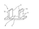
本実施例の固定部材1は、図1に示すように、底板部2の内側寄りに適宜間隔を置いて2個の壁部3を立設して構成され、前記2個の壁部3の内側と底板部2とで形成される凹状部を瓦桟木受け部4とし、更に、前記2個の壁部3の外側と底板部2とで形成される左右のL状部を断熱材受け部5としている。また、2個の壁部の外側には断熱材係合部13が設けられている。
Example 1
As shown in FIG. 1, the
図1に示した固定部材1は、本発明の基本形態を斜視図で示したものであるが、該固定部材1と、瓦桟木及び断熱材との関係を順を追って以下に説明する。
図2(a)に示したように、野地板6の上に敷設した防水シート7上に、固定部材1を適宜間隔をおいて配置し、凹状部からなる瓦桟木受け部4に瓦桟木8を配置し、隣接する固定部材1の間のL状部からなる断熱材受け部5には断熱材9を配設している。
The fixing
As shown in FIG. 2 (a), the fixing
また、図2(b)に示したように、固定部材1における瓦桟木受け部4の凹状部開放端に沿った長さは特に規制はないが、長尺の瓦桟木8の長さと同一にする必要はなく、前述したようにその長さDを略20〜100mm程度に、また、取付ピッチEを略300〜500mmにし、瓦桟木8の長手方向の所々に設ければ十分である。なお、固定部材1の、凹状部を形成して瓦桟木8を嵌設する2個の壁部の内側寸法Aは略30〜60mm、壁部と底板部の端部との寸法Bは略5〜20mm、壁部及び底板部の厚さ寸法Cは2〜5mm程度が好適である。
In addition, as shown in FIG. 2B, the length of the fixing
なお、図2(b)に示したように、長手方向に配設された固定部材1間で、且つ瓦桟木8と断熱材9との間には隙間10が形成されるので、瓦等(図示せず)から侵入した雨水等はこの隙間10を伝って流下し、さらに防水シート7上を軒先方向に向かって流下し排出される。
As shown in FIG. 2 (b), a
実施例2
実施例1は固定部材1における立設した壁部3の上端面と断熱材9の上面とが面一で、且つ壁部3の上端面が露出している形態の場合を示した。本実施例では壁部3の上端面が覆われる形態について説明する。なお、以下の説明においては、前述の実施例1と相違する点を中心に説明する。
Example 2
Example 1 showed the case where the upper end surface of the
本実施例の固定部材1は、図3に示すように、2個の壁部3の上部に面取部11を設け、断熱材9の幅寸法を僅かに大きめにとった上、該断熱材9を上から押し込み、固定した形態である。
As shown in FIG. 3, the fixing
実施例3
本実施例の固定部材1は、図4に示すように、2個の壁部3の外側に面取部11とこれに連続する引掛部12とからなる断熱材係合部13を設けた形態である。
本実施例の構成によれば、前述の実施例2で示したと同様に、断熱材9を上から押し込めば、隣接する固定部材1の左右の壁部3にそのまま固定される形態であり、即ち、断熱材9が一旦装着されると、あとは断熱材係合部13の引掛部12に引っ掛かって不用意に上方に離脱するようなことはなく、さらに安定して固定保持されるという効果がある。
Example 3
As shown in FIG. 4, the fixing
According to the configuration of the present embodiment, as shown in the above-described second embodiment, when the
実施例4
本実施例の固定部材1は、図5(a)に示すように、2個の壁部3の内側にそれぞれ円弧状の狭小部14を設けた形態で、対向する狭小部14の巾寸法Wは、瓦桟木8の巾寸法Kより僅かに狭くしている。これによって、瓦桟木8を瓦桟木受け部4に押し込めば、狭小部14によって両側から締め付けられた状態で固定される。狭小部14の設ける位置には制限はないが、壁部3の上方の位置に設けた方が瓦桟木8を挿入する際、壁部3は撓み易く弾性変形するので装着し易い。
Example 4
As shown in FIG. 5A, the fixing
この構成によって、瓦桟木8の長手方向の所定箇所に、予め固定部材1を嵌着させておくことができ、この工法を仮組み付け時等に適用すれば極めて効率的である。例えば、施工時において、作業者は固定部材1が装着された状態の瓦桟木8を、そのまま野地板上に運び、全体配置の様子を確認しながら容易に配設することができる。
With this configuration, the fixing
また、図5(b)に示すように、アルミ等の押出成形工法によって該狭小部14と前述で説明した断熱材係合部13とを一体的に形成することもでき、これによって瓦桟木8と断熱材9両部材の取付施工性が一段と向上する。
Further, as shown in FIG. 5 (b), the
実施例5
本実施例の固定部材1は、図6に示すように、前述の実施例4の図5(a)における円弧状の狭小部14をテーパー状にしたこと以外は実施例4の場合と同様である。
本実施例における固定部材1の両壁部3にテーパー形状の狭小部14Aを形成したことによって、瓦桟木8を瓦桟木受け部4に嵌設する作業が一層スムーズになるとともに、テーパーの先端部14Bが瓦桟木8の両側に食い込むような状態で密着するので瓦桟木8に固定部材1は強固に仮止めされるというメリットがある。
Example 5
As shown in FIG. 6, the fixing
Since the tapered
実施例6
前述の実施例5において、固定部材1の両壁部3の上部にテーパー形状の狭小部14Aを形成し、この狭小部14Aと壁部3の弾性変形によって桟木受け部4に瓦桟木8を挿設した際、瓦桟木8に固定部材1が仮固定できることを説明したが、これと同機能を有する他の例を説明する。
Example 6
In the above-described fifth embodiment, the tapered
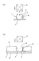
本実施例の固定部材1は、図7(a)、(b)に示すように、底板部2の内側寄りに適宜間隔を置き、且つ内側寄りに僅かに傾斜してその内側の角度が共に90度より小さくした2個の壁部3が立設している。そして2個の壁部3の上端が最も狭くなった狭小部14を形成している。
As shown in FIGS. 7 (a) and 7 (b), the fixing
また、壁部3の上部先端には前述と同様の断熱材係合部13が設けられ、底板部2の中央には長手方向に排水用凹部17が設けられ、さらに底板部2の中央には釘、ビス等の固定手段用透孔18が設けられている。また、底板部2の両端の断熱材受け部5の下部には軽量化と材料低減のための空間部19が設けられている。
Further, a heat insulating
本構成によっても、瓦桟木8の長手方向の所定箇所に、予め固定部材1を嵌着させておけば該固定部材1は、壁部3の弾性変形力によって瓦桟木8を両側に密着し保持されるので、この工法を適用すれば極めて施工作業が効率的である。
また、底板部2の中央に排水用凹部17を設けたことにより、瓦桟木と壁部3の隙間に雨水が侵入した場合においても、雨水はこの排水用凹部17を通過して流出する。また、詳しくは後述するが、底板部2の中央に釘、ビス等固定手段用透孔18を設けたことにより、瓦桟木と固定部材とを釘、ビス等の固定手段によって野地板に固定する作業が容易となる。
Also in this configuration, if the fixing
Further, since the
実施例7
本実施例では、実施例6で示した図7の固定部材1を使って瓦桟木及び断熱材を挿設する形態を説明する。図8(a)に示した瓦桟木8は固定部材1の2つの壁部2で両側から押しつけられ仮固定されている。また、固定部材1の両壁部3と、本固定部材1の左右に同様に配設される固定部材(図示せず)の壁部との間には、断熱材9が上から押し込まれる形で挿設され、断熱材係合部13によって浮き上がらないように固定されている。
また、固定部材1の底板部に排水用凹部17を設けたことにより、瓦桟木8と壁部3との間に雨水が侵入してもこの排水用凹部17から排水され、同時に瓦桟木8の下面は乾燥し易くなるので瓦桟木8の耐久性が良いというメリットもある。
また、図8(b)は、同一サイズの固定部材1を用いて、瓦桟木8の高さ寸法が大きく、且つ断熱材9の厚さを大にして挿設する場合を示す。
Example 7
A present Example demonstrates the form which inserts a tile crosspiece and a heat insulating material using the fixing
Further, by providing the drain
Moreover, FIG.8 (b) shows the case where the height dimension of the
実施例8
本実施例では、上記固定部材を用いて施工する瓦屋根外断熱工法について説明する。
図9に示すように、まず、狭小部14を有する固定部材1を、予め、瓦桟木8の下面に、適宜間隔をおいて予め定められた所定の位置に取り付けた状態にしておき、次に、野地板6上に敷設した防水シート7上に、該固定部材1を下方にして配置し、釘15a等の固定手段により野地板6等に固定する。続いて、前記壁部3の外側と底板部2とで形成されるL状部からなる断熱材受け部5に断熱材9を挿設するとともに、更に、瓦桟木8に瓦16を引っ掛けるように配設し、釘15b等の固定手段により野地板6及び/又は瓦桟木8に固定する。
Example 8
A present Example demonstrates the tile roof outer heat insulation construction method constructed using the said fixing member.
As shown in FIG. 9, first, the fixing
このように、本実施例における固定部材を用いた瓦屋根外断熱工法は、極めて簡易な構造を有し、機械的に固定するので、その施工性に優れるとともにこれまで用いられていた接着剤類を一切使用することがないので、耐久信頼性が著しく向上する。さらに解体時の施工性も容易であり、修繕やリフォームのみならず廃棄処理やリサイクルも簡易に実施できる。 Thus, the tile roof outer heat insulation method using the fixing member in this embodiment has a very simple structure and is mechanically fixed, so that it has excellent workability and adhesives that have been used so far. The durability and reliability are remarkably improved. Furthermore, workability at the time of dismantling is easy, and not only repair and renovation but also disposal and recycling can be performed easily.
本発明の瓦桟木及び断熱材固定部材及びこれを用いた瓦屋根外断熱工法は、極めて簡単な構造を有し、機械的・物理的に固定する方法を採用しているので、その施工性は飛躍的に向上するものであり、しかも従来用いられていた接着剤類を一切使用することがなく、従って接着剤の有する化学的特性に左右されないので、耐久信頼性が著しく向上し、さらには解体時の作業性も容易なので修繕やリフォームのみならず、廃棄処理やリサイクルも簡易に実施可能である。 The tile pier and the heat insulator fixing member according to the present invention and the tile roof outer heat insulation method using the same have an extremely simple structure, and adopt a method of mechanically and physically fixing, so the workability thereof is It is a drastic improvement, and it does not use any adhesives that have been used in the past, so it does not depend on the chemical properties of the adhesive, so the durability reliability is remarkably improved, and further disassembly Since workability at the time is also easy, not only repairs and renovations, but also disposal and recycling can be performed easily.
1 (瓦桟木及び断熱材)固定部材
2 底板部
3 壁部
4 瓦桟木受け部
5 断熱材受け部
6 野地板
7 防水シート
8 瓦桟木
9 断熱材
10 隙間
11 面取部
12 引掛部
13 断熱材係合部
14 狭小部
14A テーパー状の狭小部
14B 先端部
15a、15b 釘(固定手段)
16 瓦
17 排水用凹部
18 釘、ビス等固定手段用透孔
19 空間部
DESCRIPTION OF SYMBOLS 1 (Tile timber and heat insulating material) Fixing
16
Claims (9)
Priority Applications (1)
| Application Number | Priority Date | Filing Date | Title |
|---|---|---|---|
| JP2004057184A JP3889748B2 (en) | 2004-03-02 | 2004-03-02 | Tile pier, insulation fixing member, and tile roof outer insulation method using the same |
Applications Claiming Priority (1)
| Application Number | Priority Date | Filing Date | Title |
|---|---|---|---|
| JP2004057184A JP3889748B2 (en) | 2004-03-02 | 2004-03-02 | Tile pier, insulation fixing member, and tile roof outer insulation method using the same |
Publications (2)
| Publication Number | Publication Date |
|---|---|
| JP2005248460A JP2005248460A (en) | 2005-09-15 |
| JP3889748B2 true JP3889748B2 (en) | 2007-03-07 |
Family
ID=35029205
Family Applications (1)
| Application Number | Title | Priority Date | Filing Date |
|---|---|---|---|
| JP2004057184A Expired - Fee Related JP3889748B2 (en) | 2004-03-02 | 2004-03-02 | Tile pier, insulation fixing member, and tile roof outer insulation method using the same |
Country Status (1)
| Country | Link |
|---|---|
| JP (1) | JP3889748B2 (en) |
Cited By (1)
| Publication number | Priority date | Publication date | Assignee | Title |
|---|---|---|---|---|
| CN103291003A (en) * | 2013-05-23 | 2013-09-11 | 广东省建筑设计研究院 | Mortar laid tile structure of pitched roof and construction method of tile structure |
-
2004
- 2004-03-02 JP JP2004057184A patent/JP3889748B2/en not_active Expired - Fee Related
Cited By (2)
| Publication number | Priority date | Publication date | Assignee | Title |
|---|---|---|---|---|
| CN103291003A (en) * | 2013-05-23 | 2013-09-11 | 广东省建筑设计研究院 | Mortar laid tile structure of pitched roof and construction method of tile structure |
| CN103291003B (en) * | 2013-05-23 | 2016-06-08 | 广东省建筑设计研究院 | A kind of sleeping watt construction method of pitched roof |
Also Published As
| Publication number | Publication date |
|---|---|
| JP2005248460A (en) | 2005-09-15 |
Similar Documents
| Publication | Publication Date | Title |
|---|---|---|
| US20060080942A1 (en) | Facing unit construction | |
| US7818937B2 (en) | Roof panel | |
| US8104231B1 (en) | Ridge tile system for a roof | |
| US9863139B2 (en) | Building module, a method for making same, and a method for using same to construct a building | |
| KR20190046180A (en) | Deck plate integrated Insulation | |
| JP3889748B2 (en) | Tile pier, insulation fixing member, and tile roof outer insulation method using the same | |
| JP7541828B2 (en) | Roof structure and construction method of roof structure | |
| JP2963057B2 (en) | Metal base plate | |
| JP4181608B2 (en) | Ventilation insulation, insulation panel and insulation roof | |
| JP2015121081A (en) | Heat insulation roof structure | |
| JP2909885B2 (en) | Vertical roof structure | |
| JP6501337B2 (en) | Roof structure | |
| JP6523616B2 (en) | Insulated roof structure | |
| JP7541829B2 (en) | Roof structure and construction method of roof structure | |
| US10724244B2 (en) | Tile roofing riser | |
| JP2006028855A (en) | Tiled roof external heat insulating structure | |
| JP3883545B2 (en) | Outdoor floorboard connector, outdoor floor using the same, and outdoor floor construction method | |
| JP3329780B2 (en) | Roof shingles | |
| JP2023110587A (en) | Rain flashing ventilation member, and construction structure of the same | |
| KR200372518Y1 (en) | Structure of a waterspout for repairing guardrail of the top of the building | |
| KR200187234Y1 (en) | Main ridge flashing construction of building roof | |
| JP2005054431A (en) | Heat insulating material fixing member and external heat insulating construction method of tiled roof using the same | |
| JP2002167907A (en) | Hollow plain tile | |
| SK9550Y1 (en) | Sheet metal profile of a roof edge with coated waterproofing and profiles | |
| JPH0810616Y2 (en) | Large plate roofing structure |
Legal Events
| Date | Code | Title | Description |
|---|---|---|---|
| A977 | Report on retrieval |
Free format text: JAPANESE INTERMEDIATE CODE: A971007 Effective date: 20060804 |
|
| A131 | Notification of reasons for refusal |
Free format text: JAPANESE INTERMEDIATE CODE: A131 Effective date: 20060815 |
|
| A521 | Written amendment |
Free format text: JAPANESE INTERMEDIATE CODE: A523 Effective date: 20060927 |
|
| TRDD | Decision of grant or rejection written | ||
| A01 | Written decision to grant a patent or to grant a registration (utility model) |
Free format text: JAPANESE INTERMEDIATE CODE: A01 Effective date: 20061121 |
|
| A61 | First payment of annual fees (during grant procedure) |
Free format text: JAPANESE INTERMEDIATE CODE: A61 Effective date: 20061130 |
|
| R150 | Certificate of patent or registration of utility model |
Free format text: JAPANESE INTERMEDIATE CODE: R150 |
|
| FPAY | Renewal fee payment (event date is renewal date of database) |
Free format text: PAYMENT UNTIL: 20091208 Year of fee payment: 3 |
|
| FPAY | Renewal fee payment (event date is renewal date of database) |
Free format text: PAYMENT UNTIL: 20101208 Year of fee payment: 4 |
|
| FPAY | Renewal fee payment (event date is renewal date of database) |
Free format text: PAYMENT UNTIL: 20111208 Year of fee payment: 5 |
|
| FPAY | Renewal fee payment (event date is renewal date of database) |
Free format text: PAYMENT UNTIL: 20121208 Year of fee payment: 6 |
|
| FPAY | Renewal fee payment (event date is renewal date of database) |
Free format text: PAYMENT UNTIL: 20131208 Year of fee payment: 7 |
|
| LAPS | Cancellation because of no payment of annual fees |