JP3886097B2 - motor - Google Patents
motor Download PDFInfo
- Publication number
- JP3886097B2 JP3886097B2 JP2000345216A JP2000345216A JP3886097B2 JP 3886097 B2 JP3886097 B2 JP 3886097B2 JP 2000345216 A JP2000345216 A JP 2000345216A JP 2000345216 A JP2000345216 A JP 2000345216A JP 3886097 B2 JP3886097 B2 JP 3886097B2
- Authority
- JP
- Japan
- Prior art keywords
- rotor
- bearing
- stator
- rotation center
- center shaft
- Prior art date
- Legal status (The legal status is an assumption and is not a legal conclusion. Google has not performed a legal analysis and makes no representation as to the accuracy of the status listed.)
- Expired - Fee Related
Links
Images

Classifications
-
- H—ELECTRICITY
- H02—GENERATION; CONVERSION OR DISTRIBUTION OF ELECTRIC POWER
- H02K—DYNAMO-ELECTRIC MACHINES
- H02K7/00—Arrangements for handling mechanical energy structurally associated with dynamo-electric machines, e.g. structural association with mechanical driving motors or auxiliary dynamo-electric machines
- H02K7/08—Structural association with bearings
- H02K7/083—Structural association with bearings radially supporting the rotary shaft at both ends of the rotor
-
- H—ELECTRICITY
- H02—GENERATION; CONVERSION OR DISTRIBUTION OF ELECTRIC POWER
- H02K—DYNAMO-ELECTRIC MACHINES
- H02K37/00—Motors with rotor rotating step by step and without interrupter or commutator driven by the rotor, e.g. stepping motors
-
- H—ELECTRICITY
- H02—GENERATION; CONVERSION OR DISTRIBUTION OF ELECTRIC POWER
- H02K—DYNAMO-ELECTRIC MACHINES
- H02K37/00—Motors with rotor rotating step by step and without interrupter or commutator driven by the rotor, e.g. stepping motors
- H02K37/10—Motors with rotor rotating step by step and without interrupter or commutator driven by the rotor, e.g. stepping motors of permanent magnet type
- H02K37/12—Motors with rotor rotating step by step and without interrupter or commutator driven by the rotor, e.g. stepping motors of permanent magnet type with stationary armatures and rotating magnets
- H02K37/14—Motors with rotor rotating step by step and without interrupter or commutator driven by the rotor, e.g. stepping motors of permanent magnet type with stationary armatures and rotating magnets with magnets rotating within the armatures
Description
【0001】
【発明の属する技術分野】
本発明は、ロータを軸方向に付勢しながら回転させるタイプのモータの改良に関する。
【0002】
【従来の技術】
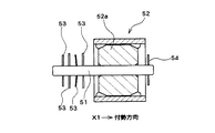
図2は、回転中心軸を軸方向一側(図2において矢示X1方向)に付勢しながら回転させるタイプのモータのロータ部分の従来構造を示している。ロータ52の回転中心軸51は、2箇所をメタル軸受け(図示省略)によって回転自在に支持される、回転中心軸51を支承する2つのメタル軸受けのうちの一方は、フレーム等の固定物に取り付けられている。そして、この固定物に取り付けられている軸受けは、付勢力によって軸方向一側に付勢されたロータ52に一側の面を受けるスラスト受けを兼ねる。
【0003】
なお、このようにロータ52を軸方向一側に付勢しながら回転させるタイプのモータでは、通常、固定物へ取り付けられている側の軸受けへロータ52を押し付けるためのバネワッシャを含む複数枚のワッシャ53を有している。すなわち、ロータ52の本体52aの端部とスラスト受けとならない側の軸受けとの間には、複数枚のワッシャ53を配置されていると共に、これら複数のワッシャ53のうちの1つあるいは2つはバネ性のあるワッシャで構成されている。これにより、ロータ52が、一側のスラスト受けを兼ねる軸受け側に押し付けられて、所定の位置で回転するようになっている。
【0004】
【発明が解決しようとする課題】
上述したようにこのタイプのモータは、ロータ52のステータ(図示省略)に対する回転位置をその付勢された側で一定させるために、ワッシャ53のバネ力を用いてロータ52を軸受けに押し当てながら回転させる構造となっている。しかしながら、各部の摩擦・摩耗を減らすためにワッシャ53を複数枚で構成する必要がある。この結果、各ワッシャ53の厚みの寸法公差が積み重なり、ロータ52の軸受けに対する位置精度もそれ程出ない。この結果、付勢力のばらつきが大きくなるという問題が生じる。
【0005】
また、スラスト受けを兼ねる軸受けが取り付けられた固定物とステータとは別体で構成されている。そのため、固定物とステータとの間にも寸法誤差や取付誤差が生じる。この結果、スラスト受けを兼ねロータの回転位置規制部となる軸受けとステータとの位置精度も出ず、ロータ52のステータに対する回転位置精度をさらに悪化させるという問題がある。
【0006】
本発明の目的は、上述の問題を鑑みて、ロータを一方の軸受け側に付勢した状態で回転させるタイプのモータにおいて、ロータのステータに対する回転位置精度を向上させると共に付勢力を安定させることが可能なモータを提供することにある。
【0007】
【課題を解決するための手段】
かかる目的を達成するために、本発明は、ステータに対向配置されたロータを軸方向に付勢する付勢部材を有すると共に、この付勢部材による付勢力を受けた状態でロータを回転させるモータにおいて、付勢力を受けてロータのスラスト位置方向への位置規制を行う位置規制部を、ステータを構成する金属製のステータコアをインサート成形した樹脂製のコイルボビンに一体的に設け、ロータの回転中心軸には両側の径より小さい径となるくびれ部を設け、位置規制部は、付勢部材の付勢力を、くびれ部にはめ込まれた樹脂製のC型ワッシャを介して間接的に受けていることを特徴としている。そのため、ロータのスラスト位置規制を行う位置規制部とステータを構成する各部、具体的にはステータコア及びコイルボビンとの位置精度を容易に出すことが可能となり、ロータのステータに対する回転位置精度が良好となる。このため、回転トルクが向上する。また、本発明では、位置規制部は、付勢部材の付勢力を、回転中心軸のくびれ部にはめ込まれた樹脂製のC型ワッシャを介して間接的に受けるようにされているので、樹脂製のコイルボビンに一体的に形成された位置規制部と樹脂製のワッシャとが摺動するため、摺動ロスが少ないものとなる。
【0008】
また、他の発明は、上述のモータにおいて、ロータの回転中心軸の一端を回転自在に受ける軸受けを軸方向移動可能なスライド軸受けとして構成し、このスライド軸受けを軸方向移動可能に保持する保持部をコイルボビンと一体的に設けると共に、保持部に付勢部材を取り付けたことを特徴としている。そのため、ロータを受けるスライド軸受けを付勢する付勢部材のコイルボビンに対する保持位置の精度が確保され、これによってロータを付勢する付勢力を制御し易くなる。その結果、ロータを位置規制部に対して必要以上に強く押し付けたり、あるいは押し付け力が弱すぎたりすることがなく、ロータがより位置精度良好な状態で回転することが可能となる。
【0009】
また、他の発明は、上述の各モータにおいて、位置規制部は、ロータの回転中心軸の他端側を支承する軸受けに設けられたことを特徴としている。そのため、構成が単純で製造しやすいものとなる。
【0011】
また、他の発明は、上述のモータにおいて、ロータの回転中心軸の他端側を軸受けから突出させ、この突出部分にリードスクリュー部を形成したことを特徴としている。従来、このタイプのモータは、ステータの一端側に軸受けを配置し、ステータの他端側にはコの字状のフレームを連結し、このフレームのステータと連結部と反対側の部分に軸受けを配置している。そしてロータの回転中心軸は、その一端をステータに配置された軸受けに支承され、他端をフレームに配置された軸受けに支承されている、このように別の部材にそれぞれ配置された両軸受けにその両端を支承させる構造であるため、軸精度を出すのが困難であるという問題が生じている。上述の発明によれば、ロータの回転中心軸を支承する両軸受けが共にステータに直接もしくは間接的に保持されており、軸精度を出すのが容易である。また、コの字状のフレームを要しないため、コンパクトを形状となり、他装置への取付スペースに制約がなく、設計の自由度が向上する。
【0012】
【発明の実施の形態】
以下、本発明の実施の形態について説明する。図1は、本発明の実施の形態のモータ全体を示す断面図である。
【0013】
図1に示すように、本発明の実施の形態のモータ(本実施の形態はステッピングモータで構成されているが、ここでは単にモータという)は、ステータ1と、ステータ1に対向配置されたロータ2とを有している。なお、ロータ2は、後述する付勢部材3によって軸方向(より具体的には、図1における矢示X方向)への付勢力を受けた状態で回転するようになっている。また、ロータ2の回転中心軸4は、その一端側がステータ1に一体的に形成された軸受け42を貫通して突出され、この貫通部分及び突出部分にリードスクリュー部6が形成されたものとなっている。
【0014】
ステータ1は、2組の金属製のステータコア11,12を軸方向に重ねた構成となっており、このステータ1の内部にはロータ2が回転自在に配置される。各ステータコア11,12は、それぞれ重ねた状態において軸方向外側に配置される外ヨーク13と、重ねた状態において隣接配置される内ヨーク14から構成されている。これら両ヨーク13,14は、磁性金属部材で構成されており、その内周側にはロータ2のマグネット部2aの外周面に対向配置される極歯15が設けられている。
【0015】
上述の2組の外ヨーク13及び内ヨーク14は、巻き線16,17を巻回するための樹脂製のコイルボビン18とインサート成形により一体的に形成され、対応する一対の内ヨーク14と外ヨーク13との間は巻き線16,17を巻回するための巻き線スペースとなっている。コイルボビン18は、各巻き線16,17を巻回するための巻線組み込み部19,20を有すると共に、内周部分にはロータ2の周囲を囲む穴部24を備えている。なお、上述の極歯15は、この穴部24内でその表面が穴の内側に露出し、後述するロータ2のマグネット部2aに対向するようになっている。
【0016】
コイルボビン18の巻線組み込み部19,20に巻回された巻き線16,17の巻き始め及び巻き終わりの部分は、それぞれ端子部22に立設された端子ピン22aに絡げられている。この端子部22は、コイルボビン18に一体的に成形されており、金属製のケース部材28の開口部より径方向外側に突出される。
【0017】
また、さらにステータ1は、図1において右側に延出され、ケース部材28の軸方向における開口部分から軸方向に突出されたキャップ部25を有している。このキャップ部25は、ロータ2の後端側に配置され、後述するようにステータ1の内部にロータ2が挿入された後にロータ2の回転中心軸21の後端(図1における右側端部)を支承するスライド軸受け41を軸方向移動可能に保持するための円形の孔25aを有している。なお、組み立て時においては、この孔25aはロータ2をステータ1の内部に挿入するための入り口部となる。このように構成されたキャップ部25は、上述のコイルボビン18に一体的に成形されたものとなっており、このキャップ部25の孔25aは上述の穴部24に連続する一連の穴となっている。
【0018】
また、キャップ部25の孔25aには、上述のスライド軸受け41をはめ込んださらに後から、スライド軸受け41の後端部分に当接しスライド軸受け41を軸受け42側に付勢するリーフスプリング3aを備えた付勢部材3がはめ込まれて保持される。すなわち、ロータ2の回転中心軸21の後端を支承するスライド軸受け41は、付勢部材3と回転中心軸21との間に配置される。そして、付勢部材3は、スライド軸受け41に対して常時軸受け42側へ付勢力を与えることによって、ロータ2を軸受け42側へ付勢して回転中心軸21を軸受け42に押し付けるものとなっており、これによりロータ2の回転を安定させるためのものとなっている。すなわち、上述のキャップ部25は、この付勢部材3を保持するための保持部となっている。
【0019】
なお、本実施の形態では、スライド軸受け41を付勢するためにリーフスプリング3aの付勢力を用いており、従来のようにバネワッシャを含む複数のワッシャを重ねる構成とはなっていない。そのため、ワッシャの枚数を従来より大幅に減らすことができ、ワッシャの厚さ寸法の公差が軸方向に積み重ならないものとなる。従って、ロータ2を付勢する付勢力が安定する。
【0020】
また、ステータ1の一方の外ヨーク13の図1において左側の端面には、軸受け保持面42aが配置され、この軸受け保持面42aの中心に軸受け42が配置されている。この軸受け42及び軸受け保持面42aは、上述の樹脂製のコイルボビン18と一体的に樹脂で成形されている。
【0021】
軸受け42は、ロータ2の回転中心軸21を回転自在に支承するラジアル軸受けであると共に、上述した付勢部材3で付勢された付勢力を受けてロータ2のスラスト位置方向への位置規制を行う位置規制部となっている。
【0022】
そのため、付勢部材3の付勢力によってロータ2が図1における矢示X方向に付勢されると、ロータ2の回転中心軸21のくびれ部21aにはめ込まれた樹脂製のC型ワッシャ21bが軸受け42の端面に押し付けられる。すなわち、C型ワッシャ21bの外径は、軸受け42の孔径より大きく形成されており、ロータ2が矢示X方向へ移動することにより、C型ワッシャ21bの端面が軸受け42の端面に押し付けられるからである。このような構成により、軸受け42は、付勢部材3の付勢力を樹脂製のC型ワッシャ21bを介して間接的に受けることとなる。
【0023】
このように、ロータ2の位置規制部を兼ねた軸受け42は、コイルボビン18と一体的に形成された樹脂製となっており、ステータ1と一体的となっている。すなわち、このモータは、ロータ2のスラスト位置規制を行う位置規制部がステータ1と一体的となっており、位置規制部のステータ1に対する位置精度を出しやすいものとなる。
【0024】
なお、本実施の形態では、上述したように軸受け42をロータ2のスラスト位置規制部としたが、軸受け42とは別にロータ2の位置規制部をステータ1に一体的に設けるようにしても良い。その場合、軸受け42は、ステータ1と一体でなくても良い。
【0025】
ステータ1の穴部24内には、ロータ2が回転自在に配置される。このロータ2は、ステータ1の極歯15に対向配置されるマグネット部2aと、このマグネット部2aの回転中心孔に接着によりマグネット部2aの軸方向端面から一側が突出するように挿通固定された金属製の回転中心軸21を有している。回転中心軸21のマグネット部2aの内側に配置する部分には、接着材溜まり溝21dが形成されている。なお、この接着剤溜まり溝21dを設けず、マグネット部2aに回転中心軸21を圧入または接着して両者を固定しても良い。
【0026】
回転中心軸21のマグネット部2aの内側に配置する部分とリードスクリュー部6との間の部分には、上述したようにくびれ部21aが形成されており、このくびれ部21aには樹脂製のC型ワッシャ21bがはめ込まれている。また、回転中心軸21のマグネット部2aから突出している部分であって、かつくびれ部21aより先端側部分の外周には、リードスクリュー部6が形成されている。なお、このリードスクリュー部6には、図示しないヘッド部材のネジ部が螺合されており、リードスクリュー部6が回転することによりこのヘッド部が図1における左右方向に移動可能となっている。
【0027】
このロータ2は、リードスクリュー部6が形成された側を先頭にして、ステータ1のキャップ部25側から穴部24内に挿入されることにより組み込まれる。すなわち、ロータ2の回転中心軸21のリードスクリュー部6側の先端をキャップ部25の孔25a内に差し込んでいき、リードスクリュー部6の先端側が穴部24及び軸受け42を通過する。そして、リードスクリュー部6の大部分を軸受け42から突出させる。
【0028】
その後、この状態でキャップ部25の孔25a内にスライド軸受け41を挿入し、さらにこのスライド軸受け41の後端側にリーフスプリング3aを当接させながら付勢部材3をキャップ部25に被せることにより、モータが組み立てられる。そして、このように組み立てられたモータは、ステータ1の巻き線16,17に電流が供給されると、ロータ2は回転中心軸21を中心として軸受け42側に付勢されながら両軸受け41,42に支承されて回転し、この回転によりリードスクリュー部6に螺合されたヘッド部材を軸方向へ移動させるようになっている。
【0029】
本発明は、上述したように、軸方向に重ねて配置される2つのステータコア11,12がコイルボビン18と共にインサート成形により一体化された構成となっている。そして、図1において左側に配置された軸受け42は、矢示X方向への付勢力を受けてロータ2のスラスト方向における回転位置を規制する位置規制部となっており、この軸受け42をコイルボビン18と一体成形した構成となっている。さらに、ロータ2を矢示X方向に付勢する付勢部材3を保持する保持部としてのキャップ部25もコイルボビン18と一体成形された構成となっている。
【0030】
そのため、位置規制部のステータ1に対する位置精度及び付勢部材3のステータ1に対する位置精度を良好とすることができる。この結果、ロータ2のステータ1に対する、特にステータ1の極歯15に対する回転位置の精度を良好にできる。すなわち、従来のように、各部材を組み立てる際の組み立て誤差の累積により、ロータ2のステータ1に対する回転位置の精度に狂いを生じさせるという不具合が生じない。このようにロータ2のステータ1に対する回転位置精度を向上させることにより、ロータ2と極歯15との間の磁気ロスを低減することが可能となるため、モータのトルクアップが図れる。逆に、トルクアップを必要としない場合は、マグネットを小さく構成することにより、材料費を低減するという効果を得ることも可能である。
【0031】
なお、上述の実施の形態は、本発明の好適な実施の形態の例であるが、これに限定されるものではなく、本発明の要旨を逸脱しない範囲において種々の変形実施が可能である。例えば、上述の実施の形態では、インサート成形により金属製のステータコア11,12を樹脂製のコイルボビン18に一体的に組み込んだが、特にインサート成形としなくても良いし、コイルボビン18を別の材料で形成しても良い。
【0032】
また、上述の実施の形態では、スライド軸受け41を保持する保持部となるキャップ部25をコイルボビン18と一体的に形成したが、キャップ部25がステータ1に対してそれ程精密な位置精度が必要ない場合には、キャップ部25は別体で形成しても良い。このように構成しても、付勢部材3がロータ2を軸受け42側に付勢し軸受け42でロータ2を受けているため、ロータ2と軸受け42の位置精度は良好となる。したがって、軸受け42が一体的に形成されているステータ1と、ロータ2との位置精度も良好なものとなる。
【0033】
また、上述の実施の形態では、付勢部材3の付勢力により軸方向にスライド移動しようとするロータ2を、樹脂製のC型ワッシャ21bを介して間接的に軸受け42で位置規制する構成としたが、C型ワッシャ21bを無くして軸受け42で直接的にロータ2を受けるようにしても良い。また、ワッシャの形状をC型ワッシャとせず、リング状としても良い。さらに、ワッシャ21bは樹脂製ではなく金属製等、他の材料で形成されても良い。またさらに、ワッシャを回転中心軸21にはめ込むのではなく、回転中心軸21の所定の位置に径方向に突出する凸部を設け、この凸部の端面がロータ2の回転時に軸受け42に摺動するような構成としても良い。さらに、ワッシャを回転中心軸21にはめ込まず、軸受け42とロータ2の間に入れるだけでも良い。
【0034】
【発明の効果】
以上説明したように、本発明では、ステータに対向配置されたロータを軸方向に付勢する付勢部材を有すると共に、この付勢部材による付勢力を受けた状態でロータを回転させるモータにおいて、付勢力を受けてロータのスラスト位置方向への位置規制を行う位置規制部をステータに一体的に設け、ロータの回転中心軸には両側の径より小さい径となるくびれ部を設け、位置規制部は、付勢部材の付勢力を、くびれ部にはめ込まれた樹脂製のC型ワッシャを介して間接的に受けている。そのため、ロータのスラスト位置規制を行う位置規制部とステータとの位置精度を容易に出すことが可能となり、ロータのステータに対する回転位置精度が良好となる。この結果、回転トルクと組み立て性を向上させることが可能となる。また、トルクアップの必要がない場合は、ロータマグネットの体積を減少させることができ、製造コストを抑えることができる。加えて、位置規制部には、樹脂製のC型ワッシャが当接するようにされているので、樹脂製のコイルボビンに一体的に形成された位置規制部と樹脂製のワッシャとが摺動することとなり、摺動ロスが少ないものとなる。
【図面の簡単な説明】
【図1】本発明の実施の形態のモータの全体構成を示す断面図である。
【図2】従来のモータの主要部となるロータ周辺部分を示した断面図である。
【符号の説明】
1 ステータ
2 ロータ
3 付勢部材
6 リードスクリュー部
11,12 ステータコア
18 コイルボビン
21 回転中心軸
21b C型ワッシャ
25 キャップ部(保持部)
41 スライド軸受け
42 軸受け(位置規制部)[0001]
BACKGROUND OF THE INVENTION
The present invention relates to an improvement in a motor of a type that rotates a rotor while urging the rotor in the axial direction.
[0002]
[Prior art]
FIG. 2 shows a conventional structure of a rotor portion of a motor of a type that rotates while rotating the rotation center axis toward one side in the axial direction (direction indicated by arrow X1 in FIG. 2). The
[0003]
Note that, in such a type of motor that rotates the
[0004]
[Problems to be solved by the invention]
As described above, this type of motor uses the spring force of the
[0005]
Further, the fixed object to which the bearing also serving as the thrust receiver is attached and the stator are configured separately. Therefore, a dimensional error and a mounting error also occur between the fixed object and the stator. As a result, there is a problem that the positional accuracy between the bearing serving as the thrust receiver and the rotational position restricting portion of the rotor and the stator is not obtained, and the rotational positional accuracy of the
[0006]
In view of the above problems, an object of the present invention is to improve the rotational position accuracy of the rotor relative to the stator and stabilize the urging force in a motor that rotates the rotor while being urged toward one of the bearings. It is to provide a possible motor.
[0007]
[Means for Solving the Problems]
In order to achieve such an object, the present invention has a biasing member that biases the rotor disposed opposite to the stator in the axial direction and rotates the rotor in a state of receiving a biasing force by the biasing member. In the above, a position restricting portion for restricting the position of the rotor in the thrust position direction by receiving an urging force is integrally provided on a resin coil bobbin in which a metal stator core constituting the stator is insert-molded, and the rotation center shaft of the rotor Has a constricted portion with a diameter smaller than the diameters on both sides, and the position restricting portion receives the urging force of the urging member indirectly via a C-type washer made of resin fitted in the constricted portion. It is characterized by. Therefore, it is possible to easily obtain the position accuracy of the position restricting portion for restricting the thrust position of the rotor and each part constituting the stator, specifically, the stator core and the coil bobbin, and the rotational position accuracy of the rotor with respect to the stator becomes good. . For this reason, rotational torque improves. Further, in the present invention, the position restricting portion is configured to receive the urging force of the urging member indirectly via a resin C-type washer fitted in the constricted portion of the rotation center shaft. Since the position restricting portion formed integrally with the coil bobbin made of resin and the resin washer slide, the sliding loss is reduced.
[0008]
According to another invention, in the above-described motor, a bearing that rotatably receives one end of the rotation center shaft of the rotor is configured as a slide bearing that can move in the axial direction, and the holding portion that holds the slide bearing so as to be movable in the axial direction. Is provided integrally with the coil bobbin, and an urging member is attached to the holding portion. For this reason, the accuracy of the holding position of the urging member for urging the slide bearing that receives the rotor with respect to the coil bobbin is ensured, which makes it easier to control the urging force that urges the rotor. As a result, the rotor is not pressed more strongly than necessary or the pressing force is not too weak, and the rotor can be rotated with better position accuracy.
[0009]
According to another invention, in each of the motors described above, the position restricting portion is provided in a bearing that supports the other end of the rotation center shaft of the rotor. Therefore, the configuration is simple and easy to manufacture.
[0011]
Another invention is characterized in that, in the above-described motor, the other end side of the rotation center shaft of the rotor protrudes from the bearing, and a lead screw portion is formed in the protruding portion. Conventionally, this type of motor has a bearing arranged on one end of the stator, a U-shaped frame connected to the other end of the stator, and a bearing on the opposite side of the stator from the connecting portion of the frame. It is arranged. The rotation center shaft of the rotor is supported by a bearing disposed at one end of the rotor and supported by a bearing disposed at the other end of the rotor. Since the both ends are supported, there is a problem that it is difficult to obtain axial accuracy. According to the above-described invention, both bearings for supporting the rotation center shaft of the rotor are both directly or indirectly held by the stator , and it is easy to obtain the shaft accuracy. In addition, since a U-shaped frame is not required, a compact shape is obtained, and there is no restriction on the mounting space for other devices, and the degree of freedom in design is improved.
[0012]
DETAILED DESCRIPTION OF THE INVENTION
Embodiments of the present invention will be described below. FIG. 1 is a cross-sectional view showing an entire motor according to an embodiment of the present invention.
[0013]
As shown in FIG. 1, a motor according to an embodiment of the present invention (this embodiment is configured by a stepping motor, but here is simply referred to as a motor) includes a stator 1 and a rotor disposed to face the stator 1. 2. The
[0014]
The stator 1 has a configuration in which two sets of
[0015]
The two sets of the
[0016]
The winding start portions and winding end portions of the winding
[0017]
Further, the stator 1 further includes a
[0018]
Further, the
[0019]
In this embodiment, the urging force of the
[0020]
Further, a bearing holding surface 42a is arranged on the left end surface of one
[0021]
The
[0022]
Therefore, when the
[0023]
Thus, the bearing 42 that also serves as the position restricting portion of the
[0024]
In the present embodiment, the
[0025]
The
[0026]
As described above, the
[0027]
The
[0028]
Thereafter, in this state, the
[0029]
As described above, the present invention has a configuration in which the two
[0030]
Therefore, the positional accuracy of the position restricting portion with respect to the stator 1 and the positional accuracy of the biasing member 3 with respect to the stator 1 can be improved. As a result, the accuracy of the rotational position of the
[0031]
The above-described embodiment is an example of a preferred embodiment of the present invention, but is not limited to this, and various modifications can be made without departing from the gist of the present invention. For example, in the above-described embodiment, the
[0032]
Further, in the above-described embodiment, the
[0033]
In the above-described embodiment, the position of the
[0034]
【The invention's effect】
As described above, in the present invention, in the motor that has a biasing member that biases the rotor disposed opposite to the stator in the axial direction and rotates the rotor in a state of receiving a biasing force by the biasing member, A position restricting portion that restricts the position of the rotor in the thrust position direction by receiving an urging force is provided integrally with the stator, and a constricted portion having a diameter smaller than the diameters on both sides is provided on the rotation center axis of the rotor. Is indirectly receiving the urging force of the urging member via a resin-made C-type washer fitted in the constricted portion . Therefore, it is possible to easily obtain the positional accuracy between the position restricting portion for restricting the thrust position of the rotor and the stator, and the rotational position accuracy of the rotor with respect to the stator is improved. As a result, it is possible to improve the rotational torque and the assemblability. Further, when there is no need to increase the torque, the volume of the rotor magnet can be reduced, and the manufacturing cost can be suppressed. In addition, since the resin-made C-type washer abuts on the position restricting portion, the position restricting portion formed integrally with the resin coil bobbin and the resin washer slide. Thus, the sliding loss is small.
[Brief description of the drawings]
FIG. 1 is a cross-sectional view showing an overall configuration of a motor according to an embodiment of the present invention.
FIG. 2 is a cross-sectional view showing a peripheral portion of a rotor that is a main part of a conventional motor.
[Explanation of symbols]
DESCRIPTION OF SYMBOLS 1
41 Slide bearing 42 Bearing (position regulating part)
Claims (4)
Priority Applications (4)
| Application Number | Priority Date | Filing Date | Title |
|---|---|---|---|
| JP2000345216A JP3886097B2 (en) | 2000-11-13 | 2000-11-13 | motor |
| KR10-2001-0068416A KR100454459B1 (en) | 2000-11-13 | 2001-11-05 | A motor |
| CNB011378786A CN1203605C (en) | 2000-11-13 | 2001-11-07 | Electric machine |
| US09/987,086 US6825587B2 (en) | 2000-11-13 | 2001-11-13 | Rotor motor with a resin coil bobbin |
Applications Claiming Priority (1)
| Application Number | Priority Date | Filing Date | Title |
|---|---|---|---|
| JP2000345216A JP3886097B2 (en) | 2000-11-13 | 2000-11-13 | motor |
Publications (3)
| Publication Number | Publication Date |
|---|---|
| JP2002153012A JP2002153012A (en) | 2002-05-24 |
| JP2002153012A5 JP2002153012A5 (en) | 2005-07-21 |
| JP3886097B2 true JP3886097B2 (en) | 2007-02-28 |
Family
ID=18819286
Family Applications (1)
| Application Number | Title | Priority Date | Filing Date |
|---|---|---|---|
| JP2000345216A Expired - Fee Related JP3886097B2 (en) | 2000-11-13 | 2000-11-13 | motor |
Country Status (4)
| Country | Link |
|---|---|
| US (1) | US6825587B2 (en) |
| JP (1) | JP3886097B2 (en) |
| KR (1) | KR100454459B1 (en) |
| CN (1) | CN1203605C (en) |
Families Citing this family (11)
| Publication number | Priority date | Publication date | Assignee | Title |
|---|---|---|---|---|
| JP4388203B2 (en) * | 2000-05-23 | 2009-12-24 | ミネベア株式会社 | Combined electromagnetic actuator device |
| JP2002191150A (en) * | 2000-12-19 | 2002-07-05 | Sankyo Seiki Mfg Co Ltd | Motor |
| JP4058324B2 (en) * | 2002-10-17 | 2008-03-05 | 日本電産サンキョー株式会社 | motor |
| JP4600886B2 (en) * | 2005-10-13 | 2010-12-22 | 日本電産サンキョー株式会社 | motor |
| JP4694997B2 (en) * | 2006-03-22 | 2011-06-08 | 日本電産サンキョー株式会社 | motor |
| JP5465391B2 (en) * | 2007-03-30 | 2014-04-09 | 日本電産サンキョー株式会社 | motor |
| JP2008263691A (en) * | 2007-04-11 | 2008-10-30 | Minebea Co Ltd | Small diameter stepping motor, its bobbin, and assembly method of motor |
| JP2008312286A (en) * | 2007-06-12 | 2008-12-25 | Nidec Sankyo Corp | Motor |
| TWM343332U (en) * | 2008-05-13 | 2008-10-21 | Tricore Corp | Motor structure capable of reducing magnetic path interference |
| KR101028241B1 (en) * | 2009-12-31 | 2011-04-11 | 엘지이노텍 주식회사 | Stepping motor |
| JP5968650B2 (en) * | 2012-03-13 | 2016-08-10 | 日本電産サンキョー株式会社 | motor |
Family Cites Families (20)
| Publication number | Priority date | Publication date | Assignee | Title |
|---|---|---|---|---|
| US84709A (en) * | 1868-12-08 | Improvement in refeating-clocks | ||
| US4308478A (en) * | 1979-02-22 | 1981-12-29 | Emerson Electric Co. | Lubrication system for dynamoelectric machine |
| FR2516318A1 (en) * | 1981-11-12 | 1983-05-13 | Crouzet Sa | ELECTRIC OVEN |
| JPH0417865Y2 (en) * | 1986-12-15 | 1992-04-21 | ||
| JPS6430436A (en) * | 1987-07-27 | 1989-02-01 | Fuji Electrochemical Co Ltd | Bearing structure for miniature motor |
| JPH0334668U (en) * | 1989-08-10 | 1991-04-04 | ||
| JP2826156B2 (en) * | 1990-03-15 | 1998-11-18 | イビデン株式会社 | Spindle motor |
| US5187400A (en) * | 1990-11-16 | 1993-02-16 | Asmo Co., Ltd. | Vibration-proof stepping motor with built-up stator |
| JP2646512B2 (en) * | 1991-12-25 | 1997-08-27 | アスモ株式会社 | Resin injection bearing for small motor |
| US5486054A (en) * | 1993-09-03 | 1996-01-23 | Minebea Co., Ltd. | Bearing system in a motor for a floppy disk drive apparatus |
| US5465020A (en) * | 1994-01-07 | 1995-11-07 | Tri-Tech, Inc. | Integral shaft bearing and bobbin for electric motors |
| US5677584A (en) * | 1995-02-09 | 1997-10-14 | General Electric Company | Bearing assembly for dynamoelectric machines |
| US5798589A (en) * | 1995-09-13 | 1998-08-25 | Zexel Corporation | Brushless motor having lubrication system for upper and lower bearings |
| US5747897A (en) * | 1995-12-28 | 1998-05-05 | Jeco Co., Ltd. | Stepping motor having improved construction to reduce parts and facilitate manufacture |
| JPH09191632A (en) * | 1996-01-08 | 1997-07-22 | Canon Inc | Stepping motor |
| JP3522037B2 (en) * | 1996-02-09 | 2004-04-26 | 株式会社三協精機製作所 | Rotor for small motor |
| JP2779348B2 (en) * | 1996-08-13 | 1998-07-23 | 株式会社渡辺製作所 | Small motor device for rotary drive mechanism |
| SG90135A1 (en) * | 1999-03-30 | 2002-07-23 | Canon Kk | Motor |
| JP2000287402A (en) * | 1999-03-31 | 2000-10-13 | Sawafuji Electric Co Ltd | Stator for multipole generator using outer rotor |
| JP2002191150A (en) | 2000-12-19 | 2002-07-05 | Sankyo Seiki Mfg Co Ltd | Motor |
-
2000
- 2000-11-13 JP JP2000345216A patent/JP3886097B2/en not_active Expired - Fee Related
-
2001
- 2001-11-05 KR KR10-2001-0068416A patent/KR100454459B1/en not_active IP Right Cessation
- 2001-11-07 CN CNB011378786A patent/CN1203605C/en not_active Expired - Fee Related
- 2001-11-13 US US09/987,086 patent/US6825587B2/en not_active Expired - Fee Related
Also Published As
| Publication number | Publication date |
|---|---|
| US6825587B2 (en) | 2004-11-30 |
| CN1353494A (en) | 2002-06-12 |
| KR20020037268A (en) | 2002-05-18 |
| KR100454459B1 (en) | 2004-10-28 |
| US20020057028A1 (en) | 2002-05-16 |
| CN1203605C (en) | 2005-05-25 |
| JP2002153012A (en) | 2002-05-24 |
Similar Documents
| Publication | Publication Date | Title |
|---|---|---|
| JP3777290B2 (en) | motor | |
| KR100631190B1 (en) | PM type stepping motor with claw-poles | |
| US6747382B2 (en) | Motor | |
| JP4727467B2 (en) | motor | |
| JP3886097B2 (en) | motor | |
| EP1496598B1 (en) | Claw-pole type stepping motor having radial dimension reduced without detriment to performance characteristic | |
| JP4568049B2 (en) | motor | |
| JP3876187B2 (en) | motor | |
| US7183676B2 (en) | Stepping motor | |
| JP3393001B2 (en) | Stepping motor | |
| JP4592519B2 (en) | motor | |
| JP3665755B2 (en) | STATOR SUPPORT MECHANISM, METHOD FOR MANUFACTURING THE STATOR SUPPORT MECHANISM, AND BRUSHLESS MOTOR HAVING THE STATOR SUPPORT MECHANISM | |
| JP2008141943A (en) | Direct-current motor and method for manufacturing the direct-current motor | |
| JP3517606B2 (en) | motor | |
| JP2858649B2 (en) | Small motor device | |
| JPH05176518A (en) | Stepping motor with lead screw | |
| JP2000014118A (en) | Stepping motor | |
| JPH09152645A (en) | Driving motor for camera opening/closing mechanism | |
| JP3598675B2 (en) | Stepping motor | |
| JP2008136302A (en) | Stepping motor | |
| JP2523960Y2 (en) | Stepping motor | |
| JP2000350401A (en) | Small-size motor and manufacture thereof | |
| JPH1066302A (en) | Small-sized motor device in rotation driving mechanism | |
| JPH0698523A (en) | Stepping motor | |
| JP3136723B2 (en) | Stator assembly for built-in stepping motor with variable damping force shock absorber |
Legal Events
| Date | Code | Title | Description |
|---|---|---|---|
| A521 | Written amendment |
Free format text: JAPANESE INTERMEDIATE CODE: A523 Effective date: 20041126 |
|
| A621 | Written request for application examination |
Free format text: JAPANESE INTERMEDIATE CODE: A621 Effective date: 20041126 |
|
| A977 | Report on retrieval |
Free format text: JAPANESE INTERMEDIATE CODE: A971007 Effective date: 20060523 |
|
| A131 | Notification of reasons for refusal |
Free format text: JAPANESE INTERMEDIATE CODE: A131 Effective date: 20060530 |
|
| A521 | Written amendment |
Free format text: JAPANESE INTERMEDIATE CODE: A523 Effective date: 20060727 |
|
| RD02 | Notification of acceptance of power of attorney |
Free format text: JAPANESE INTERMEDIATE CODE: A7422 Effective date: 20060727 |
|
| TRDD | Decision of grant or rejection written | ||
| A01 | Written decision to grant a patent or to grant a registration (utility model) |
Free format text: JAPANESE INTERMEDIATE CODE: A01 Effective date: 20061107 |
|
| A61 | First payment of annual fees (during grant procedure) |
Free format text: JAPANESE INTERMEDIATE CODE: A61 Effective date: 20061120 |
|
| R150 | Certificate of patent or registration of utility model |
Free format text: JAPANESE INTERMEDIATE CODE: R150 |
|
| LAPS | Cancellation because of no payment of annual fees |