JP3883056B2 - Image processing apparatus, image processing method, printing apparatus, image processing program, and medium on which image processing program is recorded - Google Patents
Image processing apparatus, image processing method, printing apparatus, image processing program, and medium on which image processing program is recorded Download PDFInfo
- Publication number
- JP3883056B2 JP3883056B2 JP2002116108A JP2002116108A JP3883056B2 JP 3883056 B2 JP3883056 B2 JP 3883056B2 JP 2002116108 A JP2002116108 A JP 2002116108A JP 2002116108 A JP2002116108 A JP 2002116108A JP 3883056 B2 JP3883056 B2 JP 3883056B2
- Authority
- JP
- Japan
- Prior art keywords
- image
- processing
- pixels
- image data
- gradation
- Prior art date
- Legal status (The legal status is an assumption and is not a legal conclusion. Google has not performed a legal analysis and makes no representation as to the accuracy of the status listed.)
- Expired - Fee Related
Links
Images


Description
【0001】
【発明の属する技術分野】
本発明は、画像処理装置、画像処理方法、印刷装置、画像処理プログラムおよび画像処理プログラムを記録した媒体に関する。
【0002】
【従来の技術】
従来、画像を印刷する際には、画像をドットマトリクス状の画素で多階調表現した画像データを入力し、誤差拡散法により、各画素の階調誤差を他の未変換画素に拡散させながら各画素に対応してドット形成の有無により表現した画像データに変換し、変換した画像データをプリンタに対して出力する処理を行っている。プリンタでは、設定された解像度にて、変換された画像データに基づく画像を印刷する。同誤差拡散法によると、誤差が生じないため画質はよい反面、誤差を算出して割り振っていく際の演算処理に時間がかかるため、2×2画素をまとめてブロックとし、着目ブロック全体の階調誤差を他のブロック内の未変換画素に拡散させながら同着目ブロック内の画素の画像データをまとめて変換するブロック単位処理が行われている。同ブロック単位処理によると、画像データを変換する処理を高速化することができるものの、1画素単位で変換する場合と比べて画像の分解能は低下し、画質が低下することになる。
【0003】
そこで、画像の中でブロック単位の変換処理を行っても高画質を維持可能である高明度および低明度の領域を所定のブロック処理条件が成立する領域として設定し、同条件を満たすか否かを着目ブロック内の画素全ての階調値と複数段階の閾値とを比較することにより判定している。そして、同条件を満たすと判定したとき着目ブロック内の画素の画像データをまとめて変換する処理を行い、同条件を満たさないと判定したとき着目ブロック内で画素別に画像データを変換する処理を行っている。その結果、画像データのうちドット形成密度が非常に小さいか非常に大きいことにより分解能の低下が目立たず高画質を維持可能な領域のみ、ドットはブロック単位で形成され、画像データの変換処理はある程度高速化されながら高画質が維持される。
【0004】
【発明が解決しようとする課題】
上述した従来の技術においては、ブロック処理条件の判定処理は一律に行われるため、高画質で画像を印刷させる必要がなくても、処理速度を上げて画像を印刷させることができなかった。その結果、印刷された画像を得るまでに必要以上に時間がかかると感じることがあった。そこで、このような場合に画像データの変換処理を高速化させ、印刷された画像を素早く入手したいという希望があった。
本発明は、上記課題にかんがみてなされたもので、画像を複数の画素で多階調表現した画像データから階調誤差を用いてドット形成の有無により表現した画像データに変換する処理を効率よく行い、多くの画像データ変換処理を行うときに総合的にみて変換後の画像データをより早く得ることが可能な画像処理装置、画像処理方法、印刷装置、画像処理プログラムおよび画像処理プログラムを記録した媒体の提供を目的とする。
【0005】
【課題を解決するための手段】
上記目的を達成するため、請求項1にかかる発明は、画像を複数の画素で多階調表現した画像データを入力し、変換処理済みの画素の階調誤差を未変換画素の階調値の変換に用いながらドット形成の有無により画像出力装置の出力画像を表現する画像データを生成する画像処理装置であって、上記画像出力装置にて出力される画像の画質設定に関する画質設定情報の入力を受け付ける画質設定手段と、入力された上記画質設定情報で表される画質の高低に応じた画素数の近隣した画素を処理区分とし、上記画像データを変換する同処理区分内の各未変換画素の階調値および変換処理済みの画素における上記階調誤差に基づいて、同処理区分全体の階調誤差を求めながら画像データをまとめて変換する変換処理手段とを具備する構成としてある。
【0006】
本画像処理装置のユーザは、画質設定手段により、画像出力装置にて出力される画像の画質設定に関する画質設定情報の入力を行うことができる。変換処理手段は、入力された画質設定情報で表される画質の高低に応じた画素数の近隣した画素を処理区分とし、画像データを変換する同処理区分内の各未変換画素の階調値と変換処理済みの画素における階調誤差とに基づいて、同処理区分全体の階調誤差を求めながら画像データをまとめて変換する。すると、画像出力装置からは、画質設定情報が反映された処理区分にて階調誤差を用いて変換された画像データに基づく画像が出力される。
すなわち、画像出力装置に画像を出力させるにあたり、入力された画質設定情報に合った適切な大きさの処理区分にて画像データ変換処理(以下、単に変換処理とも記載)を行うことが可能となるので、階調誤差を用いて画像データを変換する処理を効率よく行うことができ、種々の画質設定にて多くの変換処理を行うときに総合的にみて変換後の画像データをより早く得ることが可能となる。
また、請求項2にかかる発明は、画像を複数の画素で多階調表現した画像データを入力し、変換処理済みの画素の階調誤差を未変換画素の階調値の変換に用いながらドット形成の有無により画像出力装置の出力画像を表現する画像データを生成する画像処理装置であって、上記画像出力装置にて出力される画像の画質設定に関する画質設定情報の入力を受け付ける画質設定手段と、入力された上記画質設定情報で表される画像データ変換処理の処理速度に応じた画素数の近隣した画素を処理区分とし、上記画像データを変換する同処理区分内の各未変換画素の階調値および変換処理済みの画素における上記階調誤差に基づいて、同処理区分全体の階調誤差を求めながら画像データをまとめて変換する変換処理手段とを具備する構成としてある。
本画像処理装置のユーザは、画質設定手段により、画像出力装置にて出力される画像の画質設定に関する画質設定情報の入力を行うことができる。変換処理手段は、入力された画質設定情報で表される画像データ変換処理の処理速度に応じた画素数の近隣した画素を処理区分とし、画像データを変換する同処理区分内の各未変換画素の階調値と変換処理済みの画素における階調誤差とに基づいて、同処理区分全体の階調誤差を求めながら画像データをまとめて変換する。すると、画像出力装置からは、画質設定情報が反映された処理区分にて階調誤差を用いて変換された画像データに基づく画像が出力される。
すなわち、画像出力装置に画像を出力させるにあたり、入力された画質設定情報に合った適切な大きさの処理区分にて画像データ変換処理を行うことが可能となるので、階調誤差を用いて画像データを変換する処理を効率よく行うことができ、種々の画質設定にて多くの変換処理を行うときに総合的にみて変換後の画像データをより早く得ることが可能となる。
さらに、請求項3にかかる発明は、上記変換処理手段は、上記画像データを変換する処理区分内の各未変換画素の階調値および拡散されてきた上記階調誤差に基づいて、同処理区分全体の階調誤差を当該処理区分外の未変換画素に拡散させながら画像データをまとめて変換する構成としてある。
本画像処理装置のユーザは、画質設定手段により、画像出力装置にて出力される画像の画質設定に関する画質設定情報の入力を行うことができる。変換処理手段は、入力された画質設定情報に応じて一または二以上の画素数の近隣した画素を処理区分とし、画像データを変換する同処理区分内の各未変換画素の階調値と拡散されてきた階調誤差(以下、拡散誤差とも記載)とに基づいて、同処理区分全体の階調誤差を当該処理区分外の未変換画素に拡散させながら画像データをまとめて変換する。すると、画像出力装置からは、画質設定情報が反映された処理区分にて誤差拡散法を用いて変換された画像データに基づく画像が出力される。
すなわち、画像出力装置に画像を出力させるにあたり、入力された画質設定情報に合った適切な大きさの処理区分にて画像データ変換処理を行うことが可能となるので、誤差拡散法を用いて画像データを変換する処理を効率よく行うことができ、種々の画質設定にて多くの変換処理を行うときに総合的にみて変換後の画像データをより早く得ることが可能となる。
【0007】
なお、上記変換処理手段は、上記入力された画質設定情報がより高速を意味する情報になるほど上記処理区分の画素数を増やしてもよい。すると、画質設定情報がより高速を意味する情報になるほど処理区分は大きくなり、画像データの変換処理は高速化される。
【0008】
ここで、本発明を適用可能な画像出力装置は様々考えられ、例えば、画像データを入力して印刷を行うプリンタであってもよいし、表示により出力するディスプレイであってもよい。
変換前の画像データは画像を複数の画素で多階調表現したデータであればよく、複数の色データから構成されるカラー画像データであってもよいし、単独の色データから構成されるモノクロ画像データであってもよい。また、同画像データは様々な階調数とすることができ、例えば、256階調、100階調等とすることができる。さらに、同画像データから階調誤差を用いてドットを形成する際、二値化によりドットを形成してもよいし、例えば大中小のドットを形成するために二値よりも大きい多値化によりドットを形成してもよい。
【0009】
ところで、画像出力装置が設定された解像度にて画像を出力する場合、解像度を取得する解像度取得手段を設け、変換処理手段は、第一の解像度のときに上記出力画像上に占める処理区分の面積を第一の面積、同第一の解像度よりも高解像度の第二の解像度のときに上記出力画像上に占める処理区分の面積を第二の面積として、同第二の面積が同第一の面積以下となるように上記取得された解像度に応じて一または二以上の画素数の近隣した画素を上記処理区分としてもよい。すると、出力画像上に占める処理区分の面積は、解像度が高くなるにつれて大きくならないことになるので、高い解像度であるときの画質は最低でも低い解像度における最高画質となる。画像データの変換処理は解像度が高くなるほど時間がかかるため、ユーザは高解像度であるときの画質は低解像度における画質と同等以上であることを期待する。従って、高い解像度における画質が低い解像度における画質よりも低くなるような意味のない変換処理が行われなくなる。
【0010】
画像データをまとめて変換する画素から構成される処理区分は、複数の画素から構成されるのみならず、1画素のみから構成されてもよく、この場合であっても本発明に含まれる。また、同じ画像データに対して処理区分の画素数を変化させながら変換処理を行ってもよい。その一例として、請求項5にかかる発明のように、変換処理手段に判定手段と第一変換手段と第二変換手段を設けてもよい。ここで、判定手段は、二以上の画素数の近隣した画素をまとめてブロックとし、画像データを変換する着目ブロック内の各画素の階調値(以下、着目ブロックの階調値とも記載)に基づいて着目ブロックが所定のブロック処理条件を満たすか否かを判定する。ブロック処理条件が満たされると判定されたとき、第一変換手段が着目ブロック内の各画素の階調値と拡散誤差とに基づいて同着目ブロック全体の階調誤差を求めながら同着目ブロック内の画素の画像データ(以下、着目ブロックの画像データとも記載)をまとめて変換する。言い換えると、画像データの変換処理はブロック単位で行われることになる。
一方、ブロック処理条件が満たされないと判定されたとき、第二変換手段が着目ブロック内の未変換画素を区分した画素区分別に同未変換画素の階調値と拡散誤差とに基づいて同画素区分の階調誤差を求めながら同着目ブロックの画像データを変換可能である。言い換えると、画像データの変換処理はブロックよりも小さな画素単位で行われることになる。
【0011】
すなわち、ブロック単位で画像データの変換処理を行っても高画質を維持可能な領域をブロック処理条件が成立する領域として設定すれば、画像データのうち高画質を維持可能な領域のみドットがブロック単位で形成され、画質は低下せずに変換処理が高速化される。また、画質設定情報に応じて二以上の画素をブロックとするようにすれば、画質設定情報に応じてブロックは適切な大きさとされるので、より効率的に変換処理を行うことができる。
ここで、着目ブロック内を区分する画素は、1画素としてもよいし、複数の画素としてもよい。画素区分を1画素単位とすると、ブロック処理条件が満たされないときに1画素単位という簡易な処理にて画像データの変換処理が行われるようになり、簡易な構成にて高画質を維持しながら変換処理をさらに高速化させることができる。また、画素区分は着目ブロック内の画素を均等に区分したものであってもよいし、着目ブロック内の画素を不均等に区分したものであってもよい。
なお、本発明にいうブロックをそのまま処理区分に対応させる考え方を採用してもよい。この場合、処理区分内の画素を区分した画素区分別に同画素区分の階調誤差を求めながら同処理区分内の画素の画像データを変換可能とすればよい。
【0012】
さらに、請求項6にかかる発明のように、上記判定手段は、上記着目ブロック内の画素を区分して当該着目ブロックよりも小さく上記画素区分よりも大きい小ブロックとし、同小ブロックのうち上記画像データを変換する着目小ブロック内の各画素の階調値に基づいて当該着目小ブロックが別の所定のブロック処理条件を満たすか否かを判定し、上記第一変換手段は、上記判定手段にて上記別のブロック処理条件を満たすと判定されたとき、上記着目小ブロック全体をまとめて上記画像データを変換することにより上記着目ブロックの画像データを変換する構成としてもよい。すなわち、きめ細やかに処理区分の大きさを切り替えることが可能となり、画像データの変換処理はさらに小さいブロック単位でも行われるようになる。
なお、小ブロック内の画素を区分してさらに小さい小ブロックとするように、小ブロックを複数段階設けてもよい。
【0013】
上記変換処理手段は、異なる上記画質設定情報のそれぞれに対応する上記ブロック内の各画素の階調値の平均値が同じとなる条件のもとで、上記入力された画質設定情報がより高速を意味する情報になるほど上記処理区分の画素数を増やす構成としてもよい。すなわち、異なる画質設定情報のそれぞれに対応するブロックの階調値の平均値が同じとなる条件のもとで、画質設定情報がより高速を意味する情報になるほど処理区分は大きくなり、変換処理は高速化される。
【0014】
上記判定手段は、上記着目ブロック内の各画素の階調値の総和に基づいて当該着目ブロックが上記ブロック処理条件を満たすか否かを判定する構成としてもよい。すなわち、着目ブロックの階調値の総和を求めるだけで上記判定を行うことができる。なお、同判定手段は、着目ブロックの階調値の平均に基づいてブロック処理条件を満たすか否かを判定してもよい。ここで、着目ブロックの階調値の平均は同階調値の総和を着目ブロック内の画素数で除したものであるので、同階調値の平均を求めて判定を行うことも請求項8にかかる発明に含まれることになる。
【0015】
上記判定手段は、上記階調値の総和が基準とする第一閾値以下またはより小のとき、または、同階調値の総和が同第一閾値より大きい別の基準の第二閾値以上またはより大のとき、上記着目ブロックが上記ブロック処理条件を満たすと判定するとともに、上記画質設定情報がより高速を意味する情報であるほど同第一閾値と第二閾値との差を小さくする構成としてもよい。すなわち、着目ブロックの階調値の総和が第一閾値以下またはより小となるような階調値の小さい領域や、同総和が第二閾値以上またはより大となるような階調値の大きい領域では、ブロック単位で画像データの変換処理が行われる。例えば、階調値が小さいほどドットの形成密度を小さくさせる場合、ブロック内でドットが形成されないために分解能の低下が目立たないドットの形成密度の小さい領域や、ブロック内で全てのドットが形成されるために分解能の低下が目立たないドットの形成密度の大きい領域で、ドットはブロック単位で形成されるので、高画質を維持しながら変換処理を高速化させることができる。また、画質設定が高速になるほど、第一閾値と第二閾値との差は小さくなり、画像データのとりうる階調領域のうちブロック単位で変換処理が行われる領域が大きくなるので、変換処理は高速化される。
【0016】
ところで、ブロック処理条件に応じて処理区分を変更する際、上記変換処理手段は、異なる解像度のそれぞれに対応するブロック内の各画素の階調値の平均値が同じとなる条件のもとで、第一の解像度のときに上記出力画像上に占める処理区分の面積を第一の面積、同第一の解像度よりも高解像度の第二の解像度のときに上記出力画像上に占める処理区分の面積を第二の面積として、同第二の面積が同第一の面積以下となるように上記取得された解像度に応じて一または二以上の画素数の近隣した画素を処理区分としてもよい。すると、出力画像上に占める処理区分の面積は、異なる解像度のそれぞれに対応するブロックの階調値の平均値が同じとなる条件のもとで解像度が高くなるにつれて大きくならないことになる。
【0017】
上記画像出力装置が複数の要素色を使用して画像を出力する場合、変換処理手段は、複数の要素色別に、同要素色の濃さに応じて一または二以上の画素数の近隣した画素を上記処理区分とするとともに上記画像データを変換する同処理区分内の各未変換画素の階調値および変換処理済みの画素における上記階調誤差に基づいて同処理区分全体の階調誤差を求めながら画像データをまとめて変換してもよい。すると、画像出力装置からは、要素色の濃さが反映された処理区分にて階調誤差を用いて変換された画像データに基づく画像が出力される。
【0018】
例えば、目立たない要素色について必要以上に小さい処理区分にしないようにすれば、画像データのうち目立たない要素色の画像データについては比較的大きい処理区分単位でドットが形成され、画質は低下せずに変換処理が高速化される。
【0019】
ここで、上記変換処理手段は、上記複数の要素色の中で相対的に薄い要素色に対応する上記処理区分の画素数を同複数の要素色の中で相対的に濃い要素色に対応する上記処理区分の画素数以上とする構成としてもよい。相対的に薄い要素色に対応する処理区分は濃い要素色に対応する処理区分と同じ画素数かそれより多い画素数とされるが、薄い要素色は目立たないため、画質は低下せずに変換処理が高速化される。
【0020】
ところで、画像出力装置が設定された解像度にて画像を出力し、解像度を取得する解像度取得手段が設けられている場合、画質設定手段を設けない構成としてもよい。そこで、請求項13にかかる発明は、画像を複数の画素で多階調表現した画像データを入力して変換処理済みの画素の階調誤差を未変換画素の階調値の変換に用いながらドット形成の有無により表現することにより、設定された解像度にて画像を出力する画像出力装置の出力画像を表現する画像データを生成する画像処理装置であって、上記解像度を取得する解像度取得手段と、第一の解像度のときに上記出力画像上に占める処理区分の面積を第一の面積、同第一の解像度よりも高解像度の第二の解像度のときに上記出力画像上に占める処理区分の面積を第二の面積として、同第二の面積が同第一の面積以下となるように上記取得された解像度に応じて一または二以上の画素数の近隣した画素を処理区分とし、上記画像データを変換する同処理区分内の各未変換画素の階調値および変換処理済みの画素における上記階調誤差に基づいて、同処理区分全体の階調誤差を求めながら画像データをまとめて変換する変換処理手段とを具備する構成としてある。
また、画像を複数の画素で多階調表現した画像データを入力して各画素の階調誤差を他の未変換画素に拡散させながらドット形成の有無により表現することにより、設定された解像度にて画像を出力する画像出力装置の出力画像を表現する画像データを生成する画像処理装置であって、上記解像度を取得する解像度取得手段と、第一の解像度のときに上記出力画像上に占める処理区分の面積を第一の面積、同第一の解像度よりも高解像度の第二の解像度のときに上記出力画像上に占める処理区分の面積を第二の面積として、同第二の面積が同第一の面積以下となるように上記取得された解像度に応じて一または二以上の画素数の近隣した画素を処理区分とし、上記画像データを変換する同処理区分内の各未変換画素の階調値および拡散されてきた上記階調誤差に基づいて、同処理区分全体の階調誤差を当該処理区分外の未変換画素に拡散させながら画像データをまとめて変換する変換処理手段とを具備する構成としてもよい。
すなわち、出力画像上に占める処理区分の面積は、解像度が高くなるにつれて大きくならないことになるので、高解像度であるときの画質は最低でも低解像度における最高画質となる。従って、高解像度における画質が低解像度における画質よりも低くなるような意味のない変換処理が行われなくなる。
なお、請求項2〜12に記載された構成を請求項13にかかる画像処理装置に対応させることも可能である。
【0021】
ところで、上述した画像処理装置は、単独で実施される場合もあるし、ある機器に組み込まれた状態で他の方法とともに実施されることもあるなど、発明の思想としては各種の態様を含むものであって、適宜、変更可能である。
また、上述した画像処理を行う際の手法は、所定の手順に従って処理を進めていくうえで、その根底にはその手順に発明が存在するということは当然である。従って、本発明は方法としても適用可能であり、請求項14〜16にかかる発明においても、基本的には同様の作用となる。
さらに、変換された画像データに基づく画像を印刷する印刷手段を備える印刷装置としても適用可能であり、請求項17〜19にかかる発明においても、基本的には同様の作用となる。
【0022】
本発明を実施しようとする際に、画像処理装置にて所定のプログラムを実行させる場合もある。さらに、同プログラムを記録した媒体が流通し、同記録媒体からプログラムを適宜コンピュータに読み込むことが考えられる。そこで、そのプログラムやプログラムを記録したコンピュータ読み取り可能な記録媒体としても適用可能であり、請求項20〜23にかかる発明においても、基本的には同様の作用となる。
むろん、請求項2〜12に記載された構成を上記方法や印刷装置やプログラムやプログラムを記録した媒体に対応させることも可能であることは言うまでもない。
ここで、上記記録媒体は、磁気記録媒体や光磁気記録媒体の他、今後開発されるいかなる記録媒体であってもよい。また、一部がソフトウェアであって、一部がハードウェアで実現される場合においても本発明の思想において全く異なるものではなく、一部を記録媒体上に記録しておいて必要に応じて適宜読み込む形態のものも含まれる。さらに、一次複製品、二次複製品などの複製段階については全く問う余地なく同等である。
【0023】
【発明の効果】
以上説明したように、請求項1、2、13〜23にかかる発明によれば、画像を複数の画素で多階調表現した画像データから階調誤差を用いてドット形成の有無により表現した画像データに変換する処理を効率よく行い、多くの画像データ変換処理を行うときに総合的にみて変換後の画像データをより早く得ることが可能となる。
請求項3にかかる発明によれば、画像を複数の画素で多階調表現した画像データから誤差拡散法を用いてドット形成の有無により表現した画像データに変換する処理を効率よく行い、多くの画像データ変換処理を行うときに総合的にみて変換後の画像データをより早く得ることが可能となる。
請求項4にかかる発明によれば、意味のない画像データ変換処理が行われなくなり、種々の解像度にて多くの画像データ変換処理を行うときに総合的にみて変換後の画像データをさらに早く得ることが可能となる。
請求項5にかかる発明によれば、高画質を維持しながら処理速度をさらに向上させることが可能となる。
【0024】
請求項6にかかる発明によれば、きめ細やかに処理区分の大きさが切り替わるので、高画質を維持しながら処理速度をさらに向上させることが可能となる。
請求項7にかかる発明によれば、さらに効率的に画像データの変換処理を行うことができる。
請求項8にかかる発明によれば、簡易な構成でブロック処理条件を満たすか否かを判定することが可能となる。
請求項9にかかる発明によれば、簡易な構成で画質設定がより高速になるほど画像データの変換処理を高速化させることができる。
【0025】
請求項10にかかる発明によれば、ブロック処理条件に応じて処理区分を変更する場合に、意味のない画像データ変換処理が行われなくなり、種々の解像度にて多くの画像データ変換処理を行うときに総合的にみて変換後の画像データをさらに早く得ることが可能となる。
請求項11にかかる発明によれば、高画質を維持しながら処理速度をさらに向上させることが可能となり、多くの画像データ変換処理を行うときに総合的にみて変換後の画像データをさらに早く得ることが可能となる。
請求項12にかかる発明によれば、高画質を維持しながら処理速度をさらに向上させる構成例を提供することができる。
【0026】
【発明の実施の形態】
以下、下記の順序に従って本発明の実施形態を説明する。
(1)画像処理装置の構成の概略:
(2)画像処理装置の各種手段の構成:
(3)画像処理装置が行う処理の概略:
(4)ブロック単位の画像データ変換処理の説明:
(5)画像処理装置が行う処理の詳細:
(6)第二の実施形態:
(7)第三の実施形態:
(8)第四の実施形態:
(9)その他の変形例:
【0027】
(1)画像処理装置の構成の概略:
図1は、本発明の第一の実施形態にかかる画像処理装置を含む印刷装置(広義の印刷装置)100の概略構成を示している。本印刷装置100は、本発明にいう画像処理装置となるパーソナルコンピュータ(PC)10と、画像出力装置であるカラー印刷可能なインクジェットプリンタ20とから構成されている。
PC10は演算処理の中枢をなすCPU11を備えており、このCPU11はシステムバス10aを介してPC10全体の制御を行う。同バス10aには、ROM12、RAM13、各種ドライブ14,15、各種インターフェイス(I/F)16〜19等が接続されている。本実施形態のPC10はデスクトップ型PCを採用しているが、コンピュータとしては一般的な構成を有するものを採用可能である。
【0028】
ハードディスクドライブ14に接続されたハードディスク(HD)14aには、ソフトウェアとしてオペレーティングシステム(OS)や画像情報等を作成可能なアプリケーションプログラム(APL)等が格納されており、これらのソフトウェアは、実行時にCPU11によって適宜RAM13に転送される。そして、CPU11は、RAM13を一時的なワークエリアとして適宜アクセスしながら種々のプログラムを実行する。
入力I/F16には、キーボード16aやマウス16bが操作用入力機器として接続されるとともに、図示しないスキャナやデジタルカメラ等も接続されるようになっている。CRTI/F17には、画像データに基づく画像を表示するディスプレイ18aが接続されている。プリンタI/F19には、パラレルI/Fケーブルを介してプリンタ20が接続されている。むろん、シリアルI/FやSCSI、USB接続など種々の接続態様を採用可能である。
【0029】
プリンタ20は、シアン(C)、マゼンタ(M)、イエロー(Y)、ブラック(K)、の計4色(複数の要素色)の色インクを使用するものとする。むろん、4色以外のインクを使用するプリンタを採用してもよい。また、インク通路内に泡を発生させてインクを吐出するバブル方式のプリンタや、レーザープリンタ等、種々の印刷装置を採用可能である。
図2に示すように、プリンタ20では、CPU21、ROM22、RAM23、ASIC24、コントロールIC25、通信I/O26、I/F27がバス20aを介して接続されている。
【0030】
通信I/O26はPC10のプリンタI/F19と接続されており、プリンタ20は通信I/O26を介してPC10から送信されるCYMKに変換された画像のデータやページ記述言語等からなる印刷ジョブを受信する。また、PC10から各種要求を受信したとき、通信I/O26は対応する情報をPC10に出力する。本プリンタ20は印刷時の解像度として720 ×360dpi、1440×720dpi、2880×1440dpi 等を選択可能となっており、PC10から通信I/O26を介して解像度の選択情報を入手してRAM23に記憶しておき、解像度に応じたドット単位で印刷を行うことが可能となっている。
【0031】
カートリッジホルダ28にはCYMKのインクカートリッジ28a〜dが装着されており、インクカートリッジ28a〜d内の各インクが色別に図示しない印刷ヘッドに供給されるようになっている。ASIC24は、CPU21と所定の信号を送受信しつつヘッド駆動部29に対してCYMKデータに基づく印加電圧データを出力する。同ヘッド駆動部29は、同印加電圧データに基づいて印刷ヘッドに内蔵されたピエゾ素子への印加電圧パターンを生成し、印刷ヘッドに4色のインクを解像度に応じたドット単位で吐出させる。印刷ヘッドのインク吐出面には、4色のインクを吐出する4組のノズル列が印刷ヘッドの主走査方向に並ぶように形成され、ノズル列のそれぞれは複数のノズルが副走査方向に一定の間隔で直線状に配置されている。
I/F27に接続されたキャリッジ機構27aや紙送り機構27bは、印刷ヘッドを主走査させたり、適宜改ページ動作を行いながらメディアを順次送り出して副走査を行ったりする。そして、CPU21が、RAM23をワークエリアとして利用しながらROM22に書き込まれたプログラムに従って各部を制御する。
【0032】
PC10では、以上のハードウェアを基礎としてバイオスが実行され、その上層にてOSとAPLとが実行される。OSには、プリンタI/F19を制御するプリンタドライバ等の各種のドライバ類が組み込まれ、OSの一部となってハードウェアの制御を実行する。プリンタドライバは、プリンタI/F19を介してプリンタ20と双方向の通信を行うことが可能であり、GDI(Graphics Device Interface )等が組み込まれたOSを介してAPLから画像データを受け取って印刷ジョブを作成し、プリンタ20に送出する。そして、本発明の画像処理プログラムは、同プリンタドライバから構成される。むろん、APLにより構成することも可能である。また、HD14aは同プログラムを記録した媒体であるが、同媒体は、例えば、CD−ROM、フレキシブルディスク、光磁気ディスク、不揮発性メモリ、パンチカード、バーコード等の符号が印刷された印刷媒体、等であってもよい。むろん、モデム等の通信I/F18をインターネット網に接続し、所定のサーバにアクセスして本画像処理プログラムをダウンロードして実行させることも可能である。
【0033】
(2)画像処理装置の各種手段の構成:
図3は、上記ハードウェアと上記プリンタドライバとが協働して構築する画像処理装置の構成を模式的に示している。プリンタドライバは、各種モジュールを有しており、機能制御モジュールの制御に基づいて所定の機能を実現しつつ連携動作して画像データを変換することが可能である。そして、プリンタドライバの各モジュールに対応して、画像処理装置の各部が構成される。
解像度変換処理部は、画像データを入力し、プリンタ20の解像度に合わせて同画像データの解像度を変換する。入力する画像データは、画像をドットマトリクス状の多数の画素で多階調表現したデータであり、様々な種類がある。例えば、sRGB色空間で定義されるRGBから構成された画像データや、YUV表色系における輝度(Y成分)、Bの色差(U成分)、Rの色差(V成分)から構成された画像データ等がある。また、画像データの各成分も様々な階調数とされており、例えば、256階調、1024階調等がある。そこで、sRGBやYUV表色系等の定義に従って、画像データを広域RGB色空間内のRGB各256階調(0〜255の整数値)の階調データからなるRGBデータに変換する。色変換処理部、階調数変換処理部、インターレース処理部は、同画像データに基づいてプリンタ20に対して出力するCMYK別とされた画像データへの変換処理を行い、プリンタ20に送出する。すると、プリンタ20は、変換された画像データに基づいて、印刷用紙(メディア)上に色インクのドットを形成し、カラー画像を印刷する。
【0034】
本画像処理装置Aは、図に示す各種手段A1〜A3を備えている。
画質設定手段A1は、印刷設定モジュールに含まれており、プリンタ20にて出力される画像の画質設定に関する画質設定情報の入力を受け付ける。本画像処理装置には解像度別に最高画質モード、高画質モード、普通モード、高速モードの4段階の印刷モードが設けられており、画質設定手段A1は印刷モードを選択する操作入力を受け付け、同印刷モードを表すパラメータを画質設定情報として入力する。従って、本画像処理装置のユーザは、PC10に対して印刷モードを選択する操作入力を行うことにより、プリンタ20の出力画像の画質を選択可能となっている。
解像度取得手段A3は、解像度変換モジュールに含まれており、プリンタ20に対して設定する解像度を取得する。
【0035】
変換処理手段A2は、画質設定手段A1にて入力された画質設定情報に応じて一または二以上の画素数の近隣した画素を処理区分とし、画像データを変換する着目された処理区分内の各画素の階調値(以下、処理区分の階調値とも記載)と拡散誤差とに基づいて、同着目された処理区分全体の階調誤差を当該処理区分外の未変換画素に拡散させながら画像データをまとめて変換する。図3に示す例では、高速モードが選択されているときに2×2画素が処理区分U1とされ、高画質モードが選択されているときに1画素が処理区分U2とされている。この場合、高画質モードよりも高速モードのほうが処理区分は大きくなり、画像データの変換処理は高速化されることになる。
また、適宜、要素色CMYKの濃さに応じた画素数の近隣した画素を処理区分とする。
【0036】
さらに、高画質を維持しながら変換処理を高速化させるため、変換処理手段A2は、解像度に応じて二以上の画素数の近隣した画素をまとめてブロック(図の例では、ブロックB1)とし、画像データを変換する着目ブロック(図の例では、ブロックB2)内で所定のブロック処理条件が成立したときのみ同ブロック内で画像データをまとめて変換し、同条件が成立していないときには同ブロック内で画素を区分した画素区分別に画像データを変換するようにしている。この処理を実現するため、変換処理手段A2は、図4に示す各種手段A21〜A23を有している。
【0037】
すなわち、判定手段A21は、解像度取得手段A3にて取得された解像度に応じて二以上の画素数の近隣した画素をまとめてブロックとし、画像データを変換する着目ブロックB3の階調値に基づいてブロック処理条件を満たすか否かを判定する。図の例は、解像度として1440×720dpiが設定されているときの処理区分を示しており、着目ブロックB3は4×4画素とされている。なお、本実施形態では、取得された解像度が大きくなるほどブロックの画素数を増やすことにしている。例えば、比較的低解像度である720 ×360dpiであるときに近隣した2×2画素をブロックとし、比較的高解像度である2880×1440dpi であるときに近隣した8×8画素をブロックとする。なお、解像度が小さいとき、1画素のみを処理区分として画素別に着目画素の画像データを変換するようにしてもよい。
第一変換手段A22は、ブロック処理条件が満たされると判定されたときに、着目ブロックB3を着目された処理区分として、着目ブロックB3全体の階調誤差を当該着目ブロックB3外の未変換画素に拡散させながら同着目ブロックB3全体をまとめて画像データを変換する、ブロック単位の変換処理を行う。一方、第二変換手段A23は、ブロック処理条件が満たされないと判定されたとき、着目ブロックB3内の画素を区分したブロックより小さい画素区分U3を処理区分として、画素区分U3内の画素の階調値と拡散誤差とに基づいて画素区分U3の階調誤差を他の未変換画素に拡散させながら着目ブロックB3内の画素の画像データを変換可能である。本実施形態では、画素区分U3を1画素としている。すなわち、1画素単位の変換処理を行う。
【0038】
さらに、高画質を維持しながら変換処理を高速化させるため、判定手段A21は、着目ブロックB3内の画素を区分してさらに小さいブロックとし、同ブロックのうち画像データを変換する着目ブロックB4の階調値に基づいて所定の小ブロック処理条件(別のブロック処理条件)を満たすか否かを判定している。解像度が1440×720dpiである場合、4×4画素の着目ブロックB3をさらに小さい2×2画素のブロックとする。そして、第一変換手段A22は、小ブロック処理条件が満たされると判定されたとき、着目ブロックB4を着目された処理区分として同着目ブロックB4全体をまとめて画像データを変換する。一方、第二変換手段A23は、小ブロック処理条件も満たされないと判定されたときに、画素区分U3別に画素区分U3の階調値と拡散誤差とに基づいて同画素区分U3の階調誤差を他の未変換画素に拡散させながら着目ブロックB4の画像データを変換する。
なお、ブロック内で区分されるさらに小さいブロックは、略均等に区分されたものであってもよいし、不均等に区分されたものであってもよい。
【0039】
図5は、本画像処理装置が行う処理をフローチャートにより示している。本フローは、PC10のCPU11によって行われるものである。
APLはAPL用印刷機能を有しており、このAPL用印刷機能にてディスプレイ17aに表示される印刷実行メニューが選択されると、画像処理プログラムが起動し、印刷インターフェイス画面を表示する(ステップS105。以下、「ステップ」の記載を省略)。図6は、同印刷インターフェイス画面の一部の領域91を示している。同領域91には、各種選択欄91a〜f、各種ボタン91g,hが設けられている。
【0040】
印刷用紙選択欄91aでは、普通紙、上質紙といったメディアの種類をマウス16bにて選択入力可能である。印刷品質選択欄91bでは、フォト、ファインといった画像を印刷する際の品質を選択入力可能である。走査方向選択欄91cでは、印刷ヘッドの主走査の際に単方向のみにてドットを形成させるか双方向にてドットを形成させるかを選択入力可能である。パス数選択欄91dでは、主走査方向の1行分のドットを何回の走査で形成させるかを選択入力可能である。
印刷モード選択欄91eでは、複数段階の印刷モードのいずれかをマウス16bにて選択入力可能である。図では、印刷モードは4段階設けられ、左端が高速モードとされ、右端が最高画質モードとされている。ここで、上記選択欄91a〜dに選択入力が行われると、推奨する印刷モードを決定する処理を行い、決定した印刷モードの段階を表示する。
【0041】
インク別処理選択欄91fでは、インクの色別に画像データ変換処理を変えるか否かを選択入力可能である。より具体的に説明すると、同選択欄91fでは「する」と「しない」を選択入力可能であり、「する」が選択入力された場合には色別とされる処理区分のうちYの処理区分のみ他の色の処理区分よりも画素数を増やすことにしている。
そして、OKボタン91gがマウス16bにてクリック操作されると、各種選択欄等から印刷モード等の各種印刷パラメータを取得する(S110)。ここで、印刷モードを表すパラメータは画質設定情報であるため、S105〜S110の処理は画質設定情報の入力を受け付ける画質設定手段を構成する。
【0042】
その後、画像データを入手する(S115)。その際、画像を印刷させる解像度の選択に関する情報が含まれていれば、その情報も入手する。
次に、解像度変換処理部にて、プリンタ20に印刷させる解像度を取得する(S120)。解像度を取得する際、APLから解像度の選択に関する情報が含まれていれば、その情報に基づいて解像度を決定する。解像度の選択に関する情報が含まれていなければ、デフォルトの解像度(例えば、720 ×360dpi)を取得する。なお、上記印刷インターフェイス画面にて操作入力された内容に応じて解像度を決定して取得してもよい。このように、S120の処理は、S105〜S110の処理とともに、プリンタに設定された解像度を取得する解像度取得手段を構成する。
【0043】
さらに、入手した画像データの解像度をプリンタ20が印刷するための解像度に変換する、解像度変換処理を行う(S125)。解像度変換された画像データを構成する階調データは様々な階調数とすることができるが、本実施形態ではRGB各256階調としている。そして、階調値が大きくなるほどRGB各成分が大きくなるようにしてあり、RGB全ての階調値が0であるときはほぼブラックに相当し、RGB全ての階調値が255であるときはインクのドットが形成されないことになる。なお、入手した画像データの解像度が高い場合には、例えば一定の割合でデータを間引くことにより解像度を変換し、入手した画像データの解像度が低い場合には、例えば線形補間により画像データを補間して解像度を変換する。
【0044】
その後、色変換処理部にて、RGB別の階調データからなる画像データをCMYKのインクのそれぞれに対応した階調データからなる画像データに変換する、色変換処理を行う(S130)。その際、LUT(ルックアップテーブル)と呼ばれる色変換テーブルを参照して画像データを変換する。本実施形態のLUTは、256階調のRGBそれぞれの階調値をCMYKそれぞれについて256階調とされた階調値に対応させたテーブルであり、補間演算を前提として、例えば、17×17×17の格子点に対応した大量のデータを備えている。変換後のCMYKに基づく画像データ(以下、CMYKデータと記載)も、画像をドットマトリクス状の画素別に256階調の階調データで表現したデータであり、階調値が大きくなるほどCMYK各成分が大きくなるようにしてある。従って、階調値が大きくなるほど、印刷用紙上に形成されるドット密度は大きくなる。なお、変換後のCMYKデータの階調数も、様々な階調とすることができる。
【0045】
そして、階調数変換処理部にて、画像を多数の画素で多階調表現したCMYKデータをいわゆる誤差拡散法によりドット形成の有無により表現した画像データに変換する、階調数変換処理を行う(S135)。CMYKデータは256階調で表現されているが、プリンタ20は色インク別にドットを形成するか否かにより印刷を行うため、本実施形態ではプリンタ20に送出するデータを「ドットを形成する」意味の階調値「255」または「ドットを形成しない」意味の階調値「0」のいずれかに変換するようにしている。詳しくは後述するが、本階調数変換処理にて、一以上の画素数の近隣した画素を処理区分とし、着目された処理区分全体の階調誤差を当該処理区分外の未変換画素に拡散させながら画像データをまとめて変換する。
【0046】
その後、インターレース処理部にて、プリンタ20のドットの形成順序を考慮しながらドット形成の有無により表現した画像データを並べ替えるインターレース処理を行う(S140)。そして、解像度取得手段にて取得された解像度の選択情報とともに、最終的に得られた画像データをプリンタ20に対して送出し(S145)、本フローを終了する。すると、プリンタ20は、解像度の選択情報を入手するとともに同画像データを入手し、印刷ヘッドを駆動して解像度に対応した各色インクのドットを印刷媒体上に形成する。その結果、APLからの画像データに対応したカラー画像が印刷用紙に印刷されることになる。
【0047】
(3)画像処理装置が行う処理の概略:
次に、本画像処理装置が行う階調数変換処理について、図7のフローチャートを参照しながら説明する。なお、変換前の画像データはCMYK別とされた階調値から構成されているので、図のフローはCMYK別に行われることになるが、フローをわかりやすくするため図示を省略している。また、変換前の画像データはRAM13に記憶されているとともに、各画素から拡散させた階調誤差を記憶する領域や変換した画像データを記憶する領域もRAM13に設けられている。
まず、上記S120にて取得された解像度に応じて処理を分岐させる(S202)。本実施形態では、低解像度である720 ×360dpiのときにS204に進み、高解像度である1440×720dpiのときにS212に進み、超高解像度である2880×1440dpi のときにS220に進むようにしている。
【0048】
分岐後の各処理の最初に、S110で入力された画質設定情報に応じて処理区分決定用の各種閾値を設定する(S204,S212,S220)。詳しくは後述するが、図8に示すように、低解像度の場合には低解像度用閾値テーブルT1を参照し、高解像度の場合には高解像度用閾値テーブルT2を参照し、超高解像度の場合には超高解像度用閾値テーブルT3を参照して、画質設定情報である印刷モードを表すパラメータに対応する複数の閾値を設定する。また、印刷インターフェイス画面にてインク別の変換処理を行う設定が選択入力された場合には、Yの画像データのみ図中点線で示したイエロー用データを参照して閾値を設定する。なお、テーブルT2,T3については、イエロー用データの図示を省略している。
【0049】
そして、低解像度の場合に近隣した2×2画素をまとめてブロックとし、高解像度の場合に近隣した4×4画素をまとめてブロックとし、超高解像度の場合に近隣した8×8画素をまとめてブロックとして、画像データを変換する着目ブロックの位置を設定する(S206,S214,S222)。図9は、着目ブロックを模式的に示している。実際には縦方向の解像度に対し横方向の解像度は2倍となっているが、各画素U01〜U03を正方形で図示している。また、異なる解像度間で出力画像上の面積が同じとなるように、各画素U01〜U03と着目ブロックB01〜B03を描いている。すなわち、高解像度の場合の1画素の面積は低解像度の場合の1画素の面積の4分の1であり、超高解像度の場合の1画素の面積は低解像度の場合の1画素の面積の16分の1である。
変換前の画像データは、画像をドットマトリクス状の画素U01〜U03で256階調表現したCMYK別のデータである。そして、全画素について着目ブロックB01〜B03と同じ大きさのブロックとし、そのうちのいずれかのブロックを着目ブロックとして設定して、ブロック全体またはブロックを区分したさらに小さいブロックまたは画素別に誤差拡散法による変換処理を行う。本実施形態では、多数の画素を区分する多数のブロックが図に示す着目ブロックB01〜B03の単位で上下左右方向に整然と並んでおり、画像データの変換処理の順序は、左上のブロックから開始して順番に右上のブロックまでとし、その後一つずつ下の左端のブロックから順番に右端のブロックまでとして、最後に右下のブロックとしている。むろん、変換処理の順序は、適宜変更可能であり、解像度に応じて異なる順序とすることも可能である。
【0050】
本実施形態では、印刷させる解像度が大きくなるほどブロックの画素数を増やすようにしている。図の左右方向を横方向、上下方向を縦方向とすると、720 ×360dpi、1440×720dpi、2880×1440dpi の順に、横2画素と縦2画素の計4画素、横4画素と縦4画素の計16画素、横8画素と縦8画素の計64画素、を一つのブロックとしている。従って、ブロックの画素数は解像度に比例した数とされている。むろん、ブロック内の画素の数を解像度に比例した数としなくてもよく、1440×720dpiの場合に3×3画素や5×5画素のブロックとしてもよい。また、ブロックの構成は縦横同画素数に限定されるものではなく、例えば、横1列に並んだ複数の画素であってもよいし、横2×縦4画素といった長方形状であってもよいし、ある基準画素と同基準画素の右隣と左下と下隣の画素の計4画素をまとめたものであってもよい。
【0051】
着目ブロックの位置を設定すると、低解像度の場合には2×2画素、高解像度の場合には4×4画素、超高解像度の場合には8×8画素、の着目ブロック内で誤差拡散法を用いて変換処理を行う超高解像度用変換処理を行う(S208,S216,S224)。
詳しくは後述するが、解像度別の変換処理では、画質を低下させないように、着目ブロックが画像中で明度の高いハイライト領域すなわち明るい領域にあるのか、明度の低い暗い領域にあるのか、明度の中間的な領域にあるのか等を判定し、判定結果に応じた変換処理を行う。例えば、低解像度の場合には、変換処理の処理単位を2×2画素の着目ブロックB01全体とするか、画素U01別とするか、を切り替えながら誤差拡散法による変換処理を行う。高解像度の場合には、処理単位を4×4画素の着目ブロックB02全体、着目ブロックB02内の画素を区分してさらに小さい2×2画素のブロックB04、画素U02別、とするかを切り替えながら変換処理を行う。超高解像度の場合には、処理単位を8×8画素の着目ブロックB03全体、着目ブロックB03内の画素を区分してさらに小さい4×4画素のブロックB05、同ブロックB05の画素を区分してさらに小さい2×2画素のブロックB06、画素U03別、とするかを切り替えながら変換処理を行う。
【0052】
解像度別の変換処理を行うと、画像データの全ブロックについて変換処理を終了したか否かを判断する(S210,S218,S226)。変換処理を行っていないブロックがある場合、低解像度の場合にはS206に戻り、高解像度の場合にはS214に戻り、超高解像度の場合にはS222に戻り、前回の着目ブロックの右側にブロックがあるときには当該ブロックを着目ブロックの位置として設定し、前回の着目ブロックの右側にブロックがないときには一つ下の左端のブロックを着目ブロックとして設定する。そして、全ブロックについて変換処理を終了するまで繰り返し解像度別の変換処理を行う。
その後、上記S140のインターレース処理が行われ、プリンタ20に対してドット形成の有無により表現した画像データが送出され、設定された解像度にて画像を印刷させることになる。
【0053】
(4)ブロック単位の画像データ変換処理の説明:
図10は、2×2画素のブロック単位で誤差拡散を行いながら画像データを変換する様子を説明する説明図である。なお、変換後の画像データはRAM13内の所定領域に格納されることになるが、わかりやすく説明するため、変換処理が終了した画素については変換後の画像データを記載している。
図の上段は、着目ブロックB12の左隣のブロックB13まで誤差拡散を伴う画像データの変換処理が終了した状態を示している。図の例では、着目ブロックB12は画像中で明度の高い領域となっており、着目ブロックB12内の各画素Pa〜Pdのいずれにも階調値20(各画素内の上段に記載)が格納されているとともに、他のブロックから階調誤差50(各画素内の下段に記載)が拡散されてきているものとする。また、処理の一例として、各画素Pa〜Pdの階調値の総和(S1とする)が閾値100以下のときにブロック処理条件が成立するものとし、着目ブロックB12の階調値と拡散誤差の総和が閾値150よりも大きいときに同着目ブロックB12内の1画素にのみドットを形成するものとする。むろん、閾値には様々な値を採用することができる。
【0054】
ここで、階調値の総和S1は80となるのでブロック処理条件は成立し、同画素の拡散誤差の総和は200となり、着目ブロックB12の階調値と拡散誤差との総和は80+200=280であるので着目ブロックB12内の1画素にのみドットを形成することになる。本実施形態では、左隣のブロックB13のように、着目ブロックB12の左上の画素Paにドットを形成し(画素Paの階調値を255とし)、残りの画素Pb〜Pdの階調値を0とすることにしている。このように、着目ブロック内の所定位置の画素にのみドットを形成することにより、変換処理が簡素化されるので、画像データの変換が迅速に行われることになる。ここで、1画素にのみドットを形成する場合には、画素Pb〜Pdのいずれかにドットを形成してもよいし、着目ブロック内の画素のうち最も階調値の大きい画素にドットを形成してもよいし、ランダムに画素を選択してドットを形成してもよい。
【0055】
着目ブロック全体の階調誤差は、着目ブロックB12の階調値と拡散誤差との総和から画像データ変換後の着目ブロックの階調値の総和を差し引いた値となる。図の例では、着目ブロックB12の階調値と拡散誤差との総和は280であるから、変換後の着目ブロックB12の階調値の総和255を差し引くことにより、階調誤差は25となる。そして、着目ブロック全体の階調誤差を他のブロック内の未変換画素に拡散させる。図では、着目ブロックB12に隣接した6つの未変換画素U11〜U16に階調誤差を拡散させることになる。なお、左上のブロック内の画素や、上隣のブロック内の画素や、左隣のブロック内の画素等は変換処理済みであるので、これらの画素には階調誤差を拡散させないようにしている。
【0056】
また、同階調誤差を他のブロック内の未変換画素に対して略均等に拡散させるようにしている。上述した例では、着目ブロックB12全体の階調誤差は25であり、他のブロック内の未変換画素は6つあるので、25を6で除して小数点以下を四捨五入した「4」ずつ未変換画素に拡散させる。ここで、階調誤差が6で割り切れない場合には、未変換画素U16に拡散させる階調誤差を調整して、未変換画素U11〜U16に拡散させる階調誤差の合計を着目ブロックB12全体の階調誤差と一致させるようにしている。その結果、未変換画素U16には階調誤差「5」が拡散される。
なお、上記以外にも、様々な手法で同階調誤差を他のブロック内の未変換画素に拡散させることができる。例えば、着目ブロック全体の階調誤差を、同着目ブロックの右隣、左下、下隣、右下のブロック内の画素一つのみに拡散させてもよいし、着目ブロックに隣接していない未変換画素に階調誤差を拡散させてもよいし、未変換画素の位置に応じて同階調誤差を拡散する割合を異ならせてもよい。
このようにして、2×2画素のブロック単位で階調誤差を拡散させながら画像データをまとめて変換することができる。むろん、4×4画素、8×8画素のブロック単位でも、同様のことが言える。また、着目ブロックが画像中で明度の低い領域でも、同様の考え方でブロック単位で画像データを変換することが可能である。
【0057】
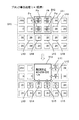
このように、上記ブロック全体の階調誤差を当該ブロック外の未変換画素に拡散させながら画像データをまとめて変換する場合もあれば、ブロック内の画素を区分したさらに小さいブロックまたは画素別に区分された領域の階調誤差を他の未変換画素に拡散させながらブロックの画像データを変換する場合もある。これらの変換処理を切り替えるため、ブロック内の各画素の階調値(以下、ブロックの階調値と記載)の総和に基づいて画像データをまとめて変換する処理区分を決定するための複数の閾値を上記S204,S212,S220で設定するようにしている。その際、図8で示した解像度別の閾値テーブルT1〜T3を参照して閾値を設定する。図11は、図8で示した閾値テーブルに格納された閾値と処理区分の画素数との関係を解像度別にブロックの階調値の平均値を表す軸に沿って示している。また、図12は同関係を表形式で表している。なお、実際の変換処理ではブロックの階調値の総和を基準とした閾値としているが、わかりやすく説明するため、図の各種閾値はブロックの階調値の平均を基準とした閾値としている。
【0058】
図11に示すように、各解像度の中で画質設定情報に対応した4段階となるように閾値を設定する。例えば、720 ×360dpiにおける最高画質モードの場合、閾値としてd10,d20を設定する。そして、図12に示すように、ブロックの階調値の平均(xとする)が基準とする閾値d10以下(d10より小としてもよい)のとき、または、平均xが同閾値d10より大きい別の基準の閾値d20より大(d20以上としてもよい)のとき、ブロック処理条件を満たすと判定するようにしている。すなわち、0≦x≦d10またはd20<x≦255のときには4画素単位の変換処理を行い、d10<x≦d20のときには画素別に変換処理を行う。
【0059】
ここで、画質設定情報がより高速を意味する情報であるほど両閾値の差を小さくすることにしている。印刷モードが最高画質モードよりも1段階画質が低い高画質モードである場合、閾値としてd11(d11>d10),d21(d21<d20)を設定する。さらに1段階画質が低い普通モードである場合、閾値としてd12(d12>d11),d22(d22<d21)を設定する。最も画質が低い高速モードである場合、閾値としてd13(d13>d12),d23(d23<d22)を設定する。そして、0≦x≦d11〜d13またはd21〜d23<x≦255のときブロック処理条件を満たすと判定する。
すなわち、図の中で閾値変化領域と示したように、比較的低階調領域において処理区分を4画素単位と1画素単位とを切り替える閾値は下限値d10〜上限値d13の範囲で変化し、比較的高階調領域において処理区分を1画素単位と4画素単位とを切り替える閾値は下限値d23〜上限値d20の範囲で変化することになる。そして、画質設定が高速になるほど、比較的低階調領域における閾値と比較的高階調領域における閾値との差は小さくなり、画像データのとりうる階調領域のうちブロック単位で変換処理が行われる領域が大きくなる。従って、簡易な構成で画質設定がより高速になるほど画像データの変換処理を高速化させることができ、従来のように高画質で画像を印刷させる必要がなくても変換処理の処理速度を上げることができないという問題を解消することができる。
【0060】
1440×720dpiでは、最高画質モードの場合、720 ×360dpiの場合と同じ閾値d10,d20の他、別の閾値d30(d30>d10),d40(d40<d20)を設定する。そして、ブロックの階調値の平均をxとして、0≦x≦d10またはd20<x≦255のときにはブロック処理条件成立として16画素単位の変換処理を行い、d10<x≦d30またはd40<x≦d20のときには別のブロック処理条件成立として4画素単位の変換処理を行い、d30<x≦d40のときには1画素単位の変換処理を行う。
【0061】
高解像度の場合には、画質設定情報がより高速を意味する情報であるほど4画素単位と1画素単位とを切り替える二つの閾値の差を小さくすることにしている。高画質モードの場合には、閾値としてd31(d31>d30),d41(d41<d40)を設定する。普通モードである場合、閾値としてd32(d32>d31),d42(d42<d41)を設定する。高速モードである場合、閾値としてd33(d33>d32),d43(d43<d42)を設定する。そして、0≦x≦d10またはd20<x≦255のときブロック処理条件を満たすと判定し、d10<x≦d31〜d33またはd41〜d43<x≦d20のとき別のブロック処理条件を満たすと判定する。
従って、比較的低階調領域において処理区分を4画素単位と1画素単位とを切り替える閾値は下限値d30〜上限値d33の範囲で変化し、比較的高階調領域において処理区分を1画素単位と4画素単位とを切り替える閾値は下限値d43〜上限値d40の範囲で変化することになる。
【0062】
ここで、高解像度の場合に処理区分を16画素単位と4画素単位とを切り替える閾値は、低解像度の場合に処理区分を4画素単位と1画素単位とを切り替える閾値d10,d20と同じにされている。この結果、高解像度の場合にまとめられる4×4画素のブロックの階調値の平均値と低解像度の場合にまとめられる2×2画素のブロックの階調値の平均値とが同じとなる条件、すなわち、インク使用量が同じとなる条件のもとで、高解像度の場合におけるプリンタの出力画像上に占める処理区分の面積は低解像度の場合における処理区分の面積と同じかまたは小さくなる。
低解像度の最高画質モードと高解像度の高速モードとで処理区分を比較すると、0≦x≦d10,d20<x≦255の階調領域では低解像度の場合に4画素であるのに対し高解像度の場合に16画素であるので、図9を参照すると出力画像上の処理区分の面積は同じになることが分かる。また、d10<x≦d33,d43<x≦d20の階調領域では低解像度の場合に1画素であるのに対し高解像度の場合に4画素であるので、やはり出力画像上の処理区分の面積は同じになる。そして、d33<x≦d43の階調領域では低解像度の場合に1画素であるのに対し高解像度の場合に1画素であるので、出力画像上の処理区分の面積は高解像度の場合のほうが小さくなる。変換処理は解像度が高くなるほど単位面積当たりの画素数が増えるため処理時間がかかることになるため、ユーザは高解像度であるときの画質は低解像度における画質と同等以上であることを期待する。上述したように各種閾値を設定することにより、解像度間で画質の逆転現象が起きない範囲で変換処理を選択することになり、高解像度であるときの画質を最低でも低解像度における最高画質にさせることができる。
【0063】
2880×1440dpi では、最高画質モードの場合、1440×720dpiの場合と同じ閾値d10,d30,d40,d20の他、別の閾値d50(d50>d30),d60(d60<d50)を設定する。そして、ブロックの階調値の平均をxとして、0≦x≦d10またはd20<x≦255のときにはブロック処理条件成立として64画素単位の変換処理を行い、d10<x≦d30またはd40<x≦d20のときには別のブロック処理条件成立として16画素単位の変換処理を行い、d30<x≦d50またはd60<x≦d40のときにはさらに別のブロック処理条件成立として4画素単位の変換処理を行い、d50<x≦d60のときには1画素単位の変換処理を行う。
【0064】
高解像度の場合には、画質設定情報がより高速を意味する情報であるほど4画素単位と1画素単位とを切り替える二つの閾値の差を小さくすることにしている。すなわち、比較的低階調側では閾値をd50〜d53の範囲で変更し、比較的高階調側では閾値をd63〜d60の範囲で変更する。
ここで、超高解像度の場合に処理区分を16画素単位と4画素単位とを切り替える閾値は、高解像度の場合に処理区分を4画素単位と1画素単位とを切り替える閾値d30,d40と同じにされている。この結果、インク使用量が同じとなる条件のもとで、超高解像度の場合におけるプリンタの出力画像上に占める処理区分の面積は高解像度の場合における処理区分の面積と同じかまたは小さくなる。従って、超高解像度であるときの画質を最低でも高解像度における最高画質にさせることができる。
なお、上述した各種閾値は、ブロックの階調値の平均または総和にかかわらず一定値とされてもよいし、ブロックの階調値の平均または総和に応じて変化させるようにしてもよい。
【0065】
また、印刷インターフェイス画面にてインク別の変換処理を行う設定が選択入力された場合には、インクの要素色CMYK別に閾値を設定する。すると、CMYK別に要素色の濃さに応じた画素数の近隣した画素を処理区分とするとともに、画像データを変換する着目された処理区分の階調値と拡散誤差に基づいて同着目された処理区分全体の階調誤差を当該処理区分外の未変換画素に拡散させながら画像データをまとめて変換することになる。本実施形態では、図8で示した解像度別閾値テーブルT1〜T3からY用の閾値のみについてはイエロー用データを参照して設定する。図13は、低解像度における閾値と処理区分の画素数との関係をブロックの階調値の平均値を表す軸に沿って示している。
【0066】
図に示すように、最高画質モードの場合には、CMK用の閾値もY用の閾値もd10,d20と同じにしてある。しかし、高画質モードの場合には、CMK用の閾値d11,d21に対し、Y用の閾値はd11’(d11’>d11),d21’(d21’<d21)となっており、Yについては4画素単位で変換処理を行う階調領域がCMKよりも広くなっている。普通モード、高速モードの場合についても同様である。すると、Yの2×2画素のブロックの階調値の平均値とCMKの2×2画素のブロックの階調値の平均値とが同じとなる条件、すなわち、インク使用量が同じとなる条件のもとで、複数の要素色CMYKの中で相対的に薄い要素色Yに対応する処理区分の画素数を相対的に濃い要素色CMKに対応する処理区分の画素数と同じかまたはそれよりも多くすることになる。ここで、YはCMKと比べて目立たないため、高画質を維持しながら処理速度をさらに向上させることが可能となる。
【0067】
なお、CMYK全て別々の閾値を設定してもよいし、インク使用量が同じとなる条件のもとで、CMに対応する処理区分の画素数をKに対応する処理区分の画素数と同じかまたはそれよりも多くするとともにYに対応する処理区分の画素数をCMに対応する処理区分の画素数と同じかまたはそれよりも多くするように閾値を設定してもよい。また、Lc(ライトシアン)、Lm(ライトマゼンタ)のインクも使用する場合には、濃い要素色をCMKとし、薄い要素色をYLcLmとして、閾値を設定してもよい。
【0068】
(5)画像処理装置が行う処理の詳細:
以下、本画像処理装置が行う処理の詳細について、解像度が1440×720dpiである場合を例にとって説明する。
図14は、図7のS216で行われる高解像度用変換処理をフローチャートにより示している。
まず、RAM13からCMYK別に4×4画素からなる着目ブロック内の各画素の階調値を読み込み(S302)、読み込んだ階調値の総和S2を算出する(S304)。ここで、図9の中程に示した着目ブロックB02内の16画素の階調値をDAi(i=1〜16)で表すと、以下の式により階調値の総和S2を算出することができる。
S2 = Σ(DAi) ・・・(1)
そして、後述するように、総和S2に基づいて、所定のブロック処理基準値である閾値D21,D22を基準として、高解像度の場合におけるブロック処理条件を満たすか否かを判定し、同条件を満たすと判定したときには4×4画素単位で変換処理を行い、同条件を満たさないと判定したときにはより小さい処理区分にて変換処理を行うようにしている。ここで、閾値D21,D22は、図7の階調数変換処理のS212にて、ブロックの階調値の平均を基準とした閾値d10,d20にブロックの画素数16を乗じた値に設定される。
【0069】
階調値の総和S2を算出すると、総和S2が0であるか否かを判断する(S306)。この判断は、後述するS310,S314,S318とともに、CMYK別に行われる。各画素の階調値は0〜255であるので、着目ブロック内の各画素の階調値が全て0であるときのみ総和S2は0となる。従って、CMYK別に見たときに着目ブロック内の各画素の階調値が全て0であるときに条件成立となってS308に進み、各画素の階調値のうち一つでも1以上のものがあれば条件不成立となってS310に進む。
S308では、着目ブロック内の画素全てをオフすなわちドットを形成しない状態とする。すなわち、着目ブロック内の変換後の画像データは全ての画素において0とされ、「ドットを形成しない」画像データとなる。その後、詳しくは後述するが、着目ブロック全体で生じる階調誤差を算出し(S324)、着目ブロック全体の階調誤差を他のブロック内の未変換画素に拡散させ(S326)、本フローを終了する。このように、着目ブロック内の各画素の階調値が全て0である場合には、後述するS312の16画素単位変換処理(その1)が行われないので変換処理を高速化させることができる。
【0070】
S310では、総和S2が閾値D21よりも大きいか否かを判断する。むろん、S2≧D21であるか否かを判断するようにしてもよい。閾値D21は、画像データの階調値の小さい領域において、16画素単位の変換処理を行っても高画質を維持可能であるか否かの境界値として予め設定されるものである。S2>D21のとき画像データの階調値の小さい領域におけるブロック処理条件を満たさないと判定してS314に進み、それ以下のとき同条件を満たすと判定してS312に進む。
【0071】
S312では、16画素単位変換処理(その1)を行い、本フローを終了する。S312が行われるのは、着目ブロックが画像中で明度の高い領域にあるときであり、ドット形成密度が小さいため、ブロック単位でドットを形成しても画像の分解能の低下は目立たず、高画質を維持することが可能である。そこで、図15の上段に示すように、4×4画素単位の変換処理を行う。なお、図の上段において、着目ブロックB22内の16画素のいずれにも階調値20が格納されているとともに、他のブロックから拡散されてきた階調誤差の総和は800とする。また、処理の一例として、階調値の総和S2が閾値400以下のときにブロック処理条件が成立するものとし、着目ブロックB22の階調値と拡散誤差の総和が閾値950よりも大きいときに同着目ブロックB22内の4画素をオンにするものとする。むろん、これらの閾値は一例にすぎない。
【0072】
ここで、総和S2はブロック処理条件成立となる320であり、拡散誤差の総和は800であるので、着目ブロックB22内の各画素の階調値と拡散誤差との総和は4画素オンとなる1120となる。本実施形態では、16画素の着目ブロック内で4画素オンとするとき、左隣のブロックB23のように、一番上の最も左の画素Peと、上から二番目の最も右の画素Pfと、上から三番目の最も左の画素Pgと、一番下の最も右の画素Phとにドットを形成する(階調値を255にする)ようにしている。また、同着目ブロック内で3画素オンとするときには画素Pe〜Pgをオンとし、2画素オンとするときには画素Pe,Pfをオンとし、1画素オンとするときには画素Peのみをオンとするようにしている。むろん、これ以外にも様々な手法により着目ブロック内で1〜4画素にドットを形成することができる。
【0073】
着目ブロック全体の階調誤差は、着目ブロックB22の階調値と拡散誤差との総和1120から画像データ変換後の着目ブロックの階調値の総和255×4=1020を差し引いた値となる。図の例では、階調誤差は100となり、着目ブロック全体の階調誤差を他のブロック内で同着目ブロックに隣接した未変換画素U21〜U30に拡散させる。本実施形態では、同階調誤差を未変換画素U21〜U30に対して略均等に拡散させるとともに、階調誤差が10で割り切れない場合には未変換画素U30に拡散させる階調誤差を調整することにしている。むろん、これ以外にも様々な手法で同階調誤差を未変換画素に拡散させることができる。
このようにして、4×4画素単位で誤差拡散法により画像データをまとめて変換することができる。
【0074】
図16は、上記16画素単位変換処理(その1)をフローチャートにより示している。
まず、4×4画素の着目ブロックについて、着目ブロックの階調値と拡散誤差との総和である補正データBxを算出する(S352)。着目ブロック内の各画素に拡散されてきた拡散誤差をそれぞれEi(i=1〜16),とすると、着目ブロック全体に拡散されてきた拡散誤差SEは、以下の式から求めることができる。
SE = Σ(Ei) ・・・(2)
着目ブロックの階調値の総和S2を用いると、補正データBxは以下の式により算出することができる。
Bx = S2 + SE ・・・(3)
そこで、RAM13から着目ブロック内の各画素の拡散誤差E1を読み出し、上記式(2),(3)により補正データBxを算出する。なお、各画素の拡散誤差は、上記S302で各画素の階調値を読み出すときに一緒に読み出しておいてもよい。
【0075】
本実施形態では、着目ブロック内で1〜4画素のオンを可能にするため、th21<th22<th23<th24である四種類の閾値を用いている。これらの閾値は、画像データの階調値の小さい領域において、それぞれ、着目ブロック内に1,2,3,4ドット形成するか否かかの境界値として予め設定されるものである。S354では、Bx>th21であるか否かを判断する。Bx≦th21のとき、着目ブロック内の画素全てをオフ、すなわち、ドットを形成せず(S356)、S372に進む。Bx>th21のとき、Bxがth22よりも大きいか否かを判断する(S358)。Bxがth22以下のとき(th21<Bx≦th22)、着目ブロック内で1画素をオン、すなわち、ドットを形成し(S360)、S372に進む。Bx>th22のとき、Bxがth23よりも大きいか否かを判断する(S362)。Bxがth23以下のとき(th22<Bx≦th23)、着目ブロック内で2画素をオンとし(S364)、S372に進む。Bx>th23のとき、Bxがth24よりも大きいか否かを判断する(S366)。Bxがth24以下のとき(th23<Bx≦th24)、着目ブロック内で3画素をオンとし(S368)、S372に進む。Bx>th24のとき、着目ブロック内で4画素をオンとし(S370)、S372に進む。
このように、ブロック単位の変換処理を行う際に着目ブロック内で複数のドットをまとめて形成することができるため、着目ブロック内で1ドットしか形成できなかった従来と比べ、画質を低下させることなく変換処理をより高速化させることが可能となる。
なお、着目ブロック内で1画素のみオンとするようにしてもよいし、全画素オフまたは4画素オンの二段階のみ切り替えるようにしてもよいし、th24’>th24なる閾値th24’を設けてBx>th24’の場合に5画素オンとするようにしてもよい。
【0076】
S372では、着目ブロック全体の階調誤差を算出する。ここで、画像データ変換後の着目ブロック内に形成されるドット数をNdotとすると、画像データ変換後の着目ブロック内における各画素の階調値の総和Sdotは、以下の式から求めることができる。
Sdot = 255 × Ndot ・・・(4)
すなわち、着目ブロック全体で生じる階調誤差Eは、以下の式のように、着目ブロック内の各画素の階調値と拡散誤差との総和から画像データ変換後の着目ブロック内における各画素の階調値の総和を差し引くことにより算出することができる。
E = S2 + SE − Sdot ・・・(5)
そして、階調誤差Eを他のブロック内の未変換画素に拡散させ(S374)、本フローを終了する。上述したように、着目ブロック外の未変換画素U21〜U30に対して階調誤差を略E/10ずつ略均等に階調誤差を拡散させる。
このようにして、4×4画素の着目ブロックにおけるブロック単位の画像データの変換処理が終了する。すなわち、図16で示したフローの処理は第一変換手段を構成することになる。
その後はS218にて全ブロックについて変換処理が終了したか否かが判断され、全ブロックについて変換処理が終了するまで繰り返し高解像度用変換処理が行われる。
【0077】
図14のS314では、総和S2が閾値D22(D22>D21)よりも大きいか(または、以上か)否かを判断する。閾値D22は、画像データの階調値の大きい領域において、16画素単位の変換処理を行っても高画質を維持可能であるか否かの境界値として設定されるものである。S2>D22のとき画像データの階調値の大きい領域におけるブロック処理条件を満たすと判定してS318に進み、それ以下のとき(D21<S2≦D22)同条件を満たさないと判定してS316に進む。なお、画像データ中でD22<S2を満たす領域は、画像中で明度の低い領域である。
【0078】
S316では、4×4画素より小さい処理区分にて変換処理を行う小ブロック変換処理を行い、本フローを終了する。図17は、その処理をフローチャートにより示している。
まず、4×4画素の着目ブロック内の画素を区分して2×2画素のさらに小さいブロック(以下、小ブロックとも記載)とし、画像データを変換する着目された小ブロック(以下、着目小ブロックと記載)の位置を設定する(S402)。図9を参照して説明すると、小ブロックBa〜Bdは着目ブロックB02内において点線または実線で区切られた2×2画素から構成され、着目小ブロックは小ブロックBa〜Bdのいずれかに設定される。そして、小ブロック単位で変換処理を行うことになる。本実施形態では、画像データの変換処理の順序を、小ブロックBa,Bb,Bc,Bdの順としている。むろん、画像データの変換処理の順序は、適宜変更可能である。また、小ブロックの構成は横2×縦2画素に限定されるものではなく、例えば横2×縦4画素といった長方形状であってもよいし、横1列に並んだ複数の画素であってもよい。また、小ブロックが全て同じ構成である必要はなく、例えば、横3×縦2画素と横1×縦2画素とに区分されてもよい。
【0079】
次に、2×2画素の着目小ブロックの階調値をCMYK別に読み込み(S404)、読み込んだ階調値の総和S3を算出する(S406)。ここで、着目小ブロック内の4画素の階調値をDAi(i=1〜4)で表すと、上記式(1)と同様にして総和S3を算出することができる。
S3 = Σ(DAi) ・・・(6)
そして、後述するように、総和S3に基づいて、所定の小ブロック処理基準値である第一閾値D31、第二閾値D32を基準として、小ブロック処理条件を満たすか否かを判定し、同条件を満たすと判定したときには2×2画素の小ブロック単位で変換処理を行い、同条件を満たさないと判定したときには1画素単位で画像データの変換処理を行うようにしている。ここで、閾値D31,D32は、図7の階調数変換処理のS212にて、ブロックの階調値の平均を基準とした閾値d30〜d33のいずれか(インク別処理を行うときYの画像データについてはd30,d31’〜d33’のいずれか),d40〜d43のいずれか(インク別処理を行うときYの画像データについてはd40,d41’〜d43’のいずれか)にブロックの画素数4を乗じた値に設定される。すなわち、入力された画質設定情報がより高速を意味する情報(高速モード側)であるほど閾値d30〜d33と閾値d40〜d43との差が小さくなり、1画素単位変換処理よりも高速にて変換処理が可能な4画素単位変換処理の行われる階調領域が広くなる。その結果、印刷モードが高速モード側となるほど変換処理はより高速にて行われることになる。また、CMYKの中で相対的に薄いYの画像データについても両閾値の差が小さくなり、1画素単位変換処理よりも高速にて変換処理が可能な4画素単位変換処理の行われる階調領域が広くなる。ここで、画像中のY成分は目立たないため、高画質が維持されるともに変換処理はさらに高速にて行われることになる。
なお、小ブロック処理条件を満たさないと判定したときに、小ブロック内の画素を2以上の画素単位で区分した画素区分とし、同画素区分別に変換処理を行ってもよい。
【0080】
総和S3を算出すると、総和S3が第一閾値D31よりも大きいか(または、以上か)否かを判断する(S408)。同判断は、S412とともにCMYK別に行われる。閾値D31は、画像データの階調値の比較的小さい領域において、小ブロック単位の変換処理を行っても高画質を維持可能であるか否かの境界値として設定されるものである。S3>D31のとき画像データの階調値の比較的小さい領域における小ブロック処理条件を満たさないと判定してS412に進み、S3≦D31のとき同条件を満たすと判定してS410に進む。
【0081】
S410では、4画素単位変換処理(その1)を行い、S418に進む。図15の下段に示すように、4×4画素の着目ブロックB22内を2×2画素に区分して小ブロックとし、小ブロック単位の変換処理を行う。小ブロック全体で1画素オンにする場合、着目小ブロックB24の左上の画素にドットを形成することにしているが、様々な手法によりドットを形成することが可能である。また、着目小ブロック全体の階調誤差を着目小ブロック外の未変換画素U41〜U45に略均等に(図の例では、25/5=5ずつ)拡散させる。むろん、これ以外にも様々な手法で階調誤差を未変換画素に拡散させることができる。このようにして、着目小ブロック全体の階調誤差を着目小ブロック外の未変換画素に拡散させながら、着目小ブロック内の画素の画像データをまとめて変換することができる。なお、着目小ブロックが画像中で明度の低い領域でも、同様の考え方で小ブロック単位で画像データを変換することが可能である。
【0082】
図18は、上記4画素単位変換処理(その1)をフローチャートにより示している。
まず、着目ブロックについて、着目ブロックの階調値と拡散誤差との総和である補正データBxを算出する(S452)。着目ブロック全体に拡散されてきた拡散誤差SEは、i=1〜4として、上記式(2)により算出することができる。そして、着目ブロックの階調値の総和S1を用いると、補正データBxは、以下の式により算出することができる。
Bx = S1 + SE ・・・(7)
次に、Bxが所定の閾値th11よりも大きいか(または、以上か)否かを判断する(S454)。Bx>th11の場合、着目ブロック内の1画素のみオン(左上の画素の階調値を255)とし、残りの3画素の階調値を0とする。一方、Bx≦th11の場合、着目ブロック内の画素全てをオフ(4画素全ての階調値を0)とする(S458)。
【0083】
その後、着目ブロック全体で生じる階調誤差を算出する(S460)。ここで、画像データ変換後の着目ブロック内に形成されるドット数をNdotとして、上記式(4)により画像データ変換後の着目ブロックの階調値の総和Sdotを求め、以下の式により着目ブロック全体で生じる階調誤差Eを算出する。
E = S1 + SE − Sdot ・・・(8)
そして、階調誤差Eを当該ブロック外の未変換画素に拡散させ(S462)、本フローを終了する。本実施形態では、着目ブロック外の未変換画素(図15の例では、U41〜U45)に対して階調誤差を略均等に拡散させている。ここで、階調誤差が拡散させる未変換画素の数で割り切れない場合には、着目ブロックの右下の未変換画素(図15の例では、U16)に拡散させる階調誤差を調整している。
このようにして、2×2画素の着目ブロックにおけるブロック単位の画像データの変換処理が終了する。すなわち、図18で示したフローの処理は、別のブロック処理条件を満たすと判定されたときにさらに小さいブロック単位で画像データを変換する意味での第一変換手段を構成する。
その後はS418にて全小ブロックについて変換処理が終了したか否かが判断され、全小ブロックについて変換処理が終了するまで繰り返し小ブロック変換処理が行われる。
【0084】
図17のS412では、着目小ブロックの階調値の総和S3が第二閾値D32よりも大きいか(または、以上か)否かを判断する。閾値D32は、画像データの階調値の比較的大きい領域において、小ブロック単位の変換処理を行っても高画質を維持可能であるか否かの境界値として予め設定されるものである。S3>D32のとき画像データの階調値の比較的大きい領域における小ブロック処理条件を満たさないと判定してS416に進み、S3≦D32のとき同条件を満たすと判定してS414に進む。
【0085】
S414では、1画素単位変換処理を行い、本フローを終了する。図19に示すように、着目ブロックB12内で画素Pa,Pb,Pc,Pdの順番に、同画素の階調誤差を他の未変換画素に拡散させながら着目ブロックB12内の画素の画像データを変換する。なお、斜線が記入された画素は、誤差拡散を伴う画像データの変換処理が終了したことを示している。ここで、未変換画素は、着目ブロックB12内であってもよいし、他のブロック内であってもよい。
まず、画素Paについて、階調値と他の画素からの階調誤差に基づいてドットを形成するか否かを判定して変換後の画像データを255または0とするとともに、画素Paの階調誤差を他の未変換画素に拡散させる。このとき、図中ブロック矢印で示したように、同画素Paに隣接する未変換画素Pb〜Pdに略均等に拡散させる。画素Pb〜Pdについても、同様にしてドットを形成するか否かを判定し、変換後の画像データを255または0とするとともに、画素Pb〜Pdに隣接する未変換画素に略均等に拡散させる。ここで、画素Pbからは未変換画素Pc,Pd,U11,U12に対して階調誤差を拡散させ、画素Pcからは未変換画素Pd,U13〜U15に対して階調誤差を拡散させ、画素Pdからは未変換画素U12,U14〜U16に対して階調領域を拡散させる。このようにして、着目ブロック内の画素別に同画素の階調誤差を拡散させながら画像データを変換することができる。
【0086】
なお、上記以外にも、様々な手法で同階調誤差を他の未変換画素に拡散させることができる。例えば、画素Pa〜Pcについては、着目ブロックB12内の未変換画素にのみ階調誤差を拡散させ、画素Pdについてのみ、他のブロック内の未変換画素に階調誤差を拡散させてもよい。また、未変換画素の位置に応じて同階調誤差を拡散する割合を異ならせるようにしてもよい。むろん、画像データを変換する順番についても様々な順番が可能であり、ブロック毎に画像データの変換処理の順序を変えてもよい。
本実施形態では、着目ブロック内の画素を1画素単位で区分して本発明にいう画素区分としているが、着目ブロック内の画素を2以上の画素単位で区分して画素区分としてもよい。例えば、横2画素×縦1画素を画素区分とすると、まず、画素Pa,Pbの階調値と拡散誤差とに基づいて同画素Pa,Pb全体の階調誤差を当該画素Pa,Pb外の未変換画素に拡散させながら同画素Pa,Pbの画像データをまとめて変換すればよい。次に、画素Pc,Pdの階調値と拡散誤差とに基づいて同画素Pc,Pd全体の階調誤差を当該画素Pc,Pd外の未変換画素に拡散させながら同画素Pc,Pcの画像データをまとめて変換すればよい。
【0087】
以上の考えのもと、上記1画素単位変換処理の詳細を図20のフローチャートに基づいて説明する。図示を省略しているが、本フローもCMYK別に行われる。
まず、着目ブロックB12内で着目画素の位置を設定し(S502)、着目画素の階調値と拡散されてきた拡散誤差とを読み込む(S504)。さらに、着目画素についての補正データCxを算出する(S506)。ここで、着目画素の階調値をSi、拡散されてきた拡散誤差をEiとすると、補正データCxは、以下の式のように階調値Siと拡散誤差Eiとの和となる。
Cx = Si + Ei ・・・(9)
その後、Cxが所定の閾値th0よりも大きいか(または、以上か)否かを判断する(S508)。Cx>th0である場合、着目画素の階調値を「ドットを形成する」意味の255とし(S510)、Cx≦th0の場合、着目画素の画像データを「ドットを形成しない」意味の0とする(S512)。
【0088】
その後、着目画素で生じる階調誤差を算出する(S514)。ここで、画像データ変換後の着目画素の画像データをDotとすると、着目画素の階調値Si、着目画素に拡散されてきた拡散誤差Eiを用いて、着目画素で生じる階調誤差E’を算出することができる。
E’ = Si + Ei − Dot ・・・(10)
さらに、図19で示したように、階調誤差E’を他の未変換画素に略均等に拡散させる(S516)。そして、着目ブロック内の全画素について変換処理を終了したか否かを判断する(S518)。着目ブロック内で変換処理を行っていない画素がある場合にはS502に戻り、次の着目画素の位置を設定して、繰り返し上述した変換処理を行う。一方、着目ブロック内の全画素について変換処理を終了した場合、1画素単位変換処理を終了する。
このようにして、2×2画素の着目ブロックにおける1画素単位の画像データの変換処理が終了する。すなわち、図20で示したフローの処理は、ブロック処理条件を満たさないと判定されたときに着目ブロック内で画素別に画像データを変換する第二変換手段を構成する。
その後、全小ブロックについて変換処理が終了するまで繰り返し小ブロック変換処理が行われる。
【0089】
図17のS416では、4画素単位変換処理(その2)を行い、その後、S418に進む。図21は、同処理をフローチャートにより示している。
まず、上記S452と同様にして、着目ブロックについての補正データBxを算出し(S552)、補正データBxが所定の閾値th12(th12>th11)よりも大きいか(または、以上か)否かを判断する(S554)。Bx>th12の場合に着目ブロック内の画素全てをオン(4画素全ての階調値を255)とし(S556)、Bx≦th12の場合に着目ブロック内の1画素のみオフ(例えば、着目ブロック内の右下の画素の階調値を0、残りの3画素の階調値を255)とする(S558)。その後、S460,S462と同様にして、着目ブロック全体の階調誤差Eを算出し(S560)、同階調誤差Eを他のブロック内の未変換画素に拡散させ(S562)、本フローを終了する。
すなわち、図21で示したフローの処理も第一変換手段を構成することになる。
【0090】
その後、全小ブロックについて変換処理が終了するまで繰り返し小ブロック変換処理が行われる。
小ブロック変換処理が終了すると、図14の高解像度用変換処理も終了して、全ブロックについて変換処理が終了するまで繰り返し高解像度用変換処理が行われる。
【0091】
ブロック処理条件を満たすと判定したときに実行される図14のS318では、16画素の着目ブロックの階調値の総和S2が255×16=4080であるか否かを判断する。各画素の階調値は0〜255であるので、着目ブロック内の各画素の階調値が全て255であるときのみ条件成立となり、S322に進む。一方、各画素の階調値のうち一つでも254以下のものがあれば条件不成立となり、S320に進む。
S320では、16画素単位変換処理(その2)を行い、その後、本フローを終了する。図22は、同処理をフローチャートにより示している。
【0092】
まず、着目ブロックについての補正データBxを算出する(S602)。本実施形態では、画像データの階調値の大きい領域において、着目ブロック内で1〜4画素のオフを可能にするため、th25<th26<th27<th28である四種類の閾値を用いているが、閾値の数は様々に設定可能である。S604では、Bxがth25よりも大きいか否かを判断する。Bx≦th25のとき、着目ブロック内の4画素をオフとし(S606)、S622に進む。Bx>th25のとき、Bxがth26よりも大きいか否かを判断する(S608)。Bx≦th26のとき、着目ブロック内で3画素をオフとし(S610)、S622に進む。Bx>th26のとき、Bxがth27よりも大きいか否かを判断する(S612)。Bx≦th27のとき、着目ブロック内で2画素をオフとし(S614)、S622に進む。Bx>th27のとき、Bxがth28よりも大きいか否かを判断する(S616)。Bxがth28以下のとき、着目ブロック内で1画素をオフとし(S618)、S622に進む。Bx>th28のとき、着目ブロック内の画素全てをオンとし(S620)、S622に進む。
このように、ブロック単位の変換処理を行う際に着目ブロック内で複数の画素をオフにすることができるため、高画質を維持しながら変換処理をより高速化させることが可能となる。
【0093】
S622では、S372と同様にして、着目ブロック全体の階調誤差Eを算出する。そして、階調誤差Eを他のブロック内の未変換画素に略均等に拡散させ(S624)、本フローを終了する。
このように、図22で示したフローの処理も第一変換手段を構成することになる。その後、全ブロックについて変換処理が終了するまで繰り返し高解像度用変換処理が行われる。
【0094】
図14のS322では、着目ブロック内の画素全てをオンとする。そして、着目ブロック全体の階調誤差Eを算出し(S324)、階調誤差Eを他のブロック内の未変換画素に略均等に拡散させて(S326)、本フローを終了する。このように、着目ブロック内の各画素の階調値が全て255である場合には、S320の16画素単位変換処理(その2)が行われないので変換処理を高速化させることができる。その後、全ブロックについて変換処理が終了するまで繰り返し高解像度用変換処理が行われる。
【0095】
このように、高解像度(1440×720dpi)の場合に4×4画素の着目ブロックで行われる画像データの変換処理は、同着目ブロックの階調値の平均またはさらに小さくした2×2画素のブロックの階調値の平均をxとして、図12で示したように切り替えられることになる。従って、S310,S314,S408,S412の判断処理は、画像データを変換する着目ブロックの階調値の総和またはさらに小さくした2×2画素のブロックの階調値の総和に基づいてブロック処理条件を満たすか否かを判定する判定手段を構成する。そして、図14で示した階調数変換処理が、画質設定情報に応じて一または二以上の画素数の近隣した画素を処理区分とし、着目された処理区分内の各画素の階調値と拡散誤差とに基づいて、誤差拡散法により画像データを変換する変換処理手段を構成することになる。
【0096】
なお、720 ×360dpiの場合に行われる低解像度用変換処理(図7のS208)は、図17で示した小ブロック変換処理と同様の処理にて行うことができるので、詳しい説明を省略する。すなわち、図7の階調数変換処理のS204にて、閾値D31を第一閾値としてブロックの階調値の平均を基準とした閾値d10〜d13のいずれかにブロックの画素数4を乗じた値に設定し、閾値D32を第二閾値としてブロックの階調値の平均を基準とした閾値d20〜d23のいずれかにブロックの画素数4を乗じた値に設定すれば、S402にて着目小ブロックの代わりに2×2画素の着目ブロックの位置を設定し、S404にて着目ブロック内の各画素の階調値を読み込み、S406にて着目ブロックの階調値の総和(S3とする)を算出することにより、4画素単位と1画素単位とを切り替えながら変換処理を行うことができる。
【0097】
また、2880×1440dpi の場合に行われる超高解像度用変換処理(図7のS224)は、図14で示した高解像度用変換処理と同様の処理にて行うことができる。すなわち、図7の階調数変換処理のS220にて、閾値D21をブロックの階調値の平均を基準とした閾値d10にブロックの画素数64を乗じた値に設定し、閾値D22をブロックの階調値の平均を基準とした閾値d20にブロックの画素数64を乗じた値に設定すれば、S312,S320にて16画素単位変換処理(その1,2)の代わりに64画素単位変換処理(その1,2)を行い、S316にて4×4画素をさらに小さいブロックとする小ブロック変換処理を行えばよい。そして、図17で示した小ブロック変換処理では、S402にて4×4画素の着目小ブロックの位置を設定し、S410,S416にて4画素単位変換処理(その1,2)の代わりに16画素単位変換処理(その1,2)を行い、S414にて1画素単位変換処理の代わりに2×2画素をさらに小さいブロックとする小ブロック変換処理を行うことにより、64画素単位、16画素単位、4画素単位、1画素単位を切り替えながら変換処理を行うことができる。このように、きめ細やかに処理区分の大きさが切り替わるので、ブロックとしては2×2画素に固定されていた従来と比べ、高画質を維持しながら処理速度をさらに向上させることが可能となる。
また、プリンタに設定された解像度が1440×720dpi以上のときのみ小ブロック変換処理を行うようにしているので、効率よく変換処理を行うことができる。
むろん、2880×1440dpi より高い解像度である場合や、720 ×360dpiより低い解像度である場合も、同様の考え方により処理区分の大きさを切り替えながら変換処理を行うことができる。
【0098】
以上説明したように、本発明によると、画像をドットマトリクス状の画素で多階調表現した画像データを入力し、各画素の階調誤差を他の未変換画素に拡散させながらドット形成の有無によりプリンタのような画像出力装置の出力画像を表現する画像データを生成するにあたり、入力された画質設定情報に合った適切な大きさの処理区分にて画像データの変換処理を行うことが可能となる。特に、入力された画質設定情報がより高速を意味する情報であるほど4画素単位変換処理と1画素単位変換処理とを切り替える際により高速にて画像データ変換処理が可能な4画素単位変換処理が行われる階調領域が広くなるので、画像データの変換処理は高速化される。従って、誤差拡散法を用いて画像データを変換する処理を効率よく行うことができ、種々の画質設定にて多くの画像データ変換処理を行うときに総合的にみて変換後の画像データをより早く得ることが可能となる。
【0099】
また、異なる解像度のそれぞれに対応するブロックの階調値の平均値が同じとなる条件のもとで、画像出力装置に設定された解像度が高くなるにつれて出力画像上に占める面積が同じかまたは小さくなるように同解像度に応じた画素数の近隣した画素を処理区分としているので、処理区分の面積は、解像度が高くなるにつれて大きくならないことになる。従って、高い解像度における画質が低い解像度における画質よりも低くなるような意味のない変換処理が行われなくなり、種々の解像度にて多くの変換処理を行うときに総合的にみて変換後の画像データをさらに早く得ることが可能となる。
【0100】
さらに、要素色CMYKの濃さに応じた画素数の近隣した画素を処理区分として誤差拡散法により画像データをまとめて変換することが可能であるので、目立たない要素色について必要以上に小さい処理区分としないようにすることにより高画質を維持しながら処理速度をさらに向上させることが可能となる。特に、異なる要素色CMYKのそれぞれに対応するブロックの階調値の平均値が同じとなる条件のもとで、要素色CMYKの中で相対的に薄い要素色Yに対応する処理区分の画素数を相対的に濃い要素色CMKに対応する処理区分の画素数以上とするので、目立たない要素色Yの画像データについては目立つ要素色CMKの画像データよりも同じかより大きい処理区分単位でドットが形成され、画質は低下せずに変換処理が高速化される。従って、複数の要素色からなる階調データで表現される画像データに対して多くの変換処理を行うときに総合的にみて変換後の画像データをさらに早く得ることが可能となる。
【0101】
加えて、解像度に合った適切な大きさの処理区分にて画像データの変換処理を行うことが可能となるので、より高解像度である場合に変換処理を高速化させることができ、変換処理を効率よく行うことができる。また、各画素の階調値の小さい領域と階調値の大きい領域の双方にて、画像データのうち高画質を維持可能な領域のみドットがブロック単位で形成されるので、高画質を維持しながら変換処理をさらに高速化させることができる。さらに、きめ細やかに画像データをまとめて変換するブロックの大きさを切り替えることにより、解像度に関係なく高画質を維持しながら変換処理を高速化することが可能となる。
【0102】
(6)第二の実施形態:
なお、本発明の画像処理プログラムを実行可能な画像処理装置と画像出力装置は、様々な構成が可能である。
例えば、プリンタは、コンピュータと一体化されたものであってもよいし、いわゆるバリアブルプリンタ等のように形成するドットの大きさが可変とされたものであってもよい。上述したフローについては、PC内で実行する以外にも、一部または全部をプリンタあるいは専用の画像処理装置で実行するようにしてもよい。画像出力装置は、印刷媒体上にドットを形成して印刷を行う装置以外であってもよく、例えば、液晶表示画面上で輝点形成の有無により画像を表現する液晶表示装置であってもよい。
また、プリンタに対してプリンタドライバによらずに解像度が設定されるようになっている場合等では、プリンタに印刷させる解像度を取得するにあたり、プリンタから解像度についての情報を入手することにより解像度を取得してもよい。
さらに、上述した実施形態ではn×n画素(nは正の整数)を処理区分やブロックとしたが、処理区分やブロックは様々な構成が可能である。例えば、解像度が1440×720dpiであるときに横4画素×縦2画素を処理区分やブロックとする等、解像度の縦横の比と一致した領域の画素を処理区分やブロックとしてもよい。すると、見た目の処理区分やブロックの大きさが縦横同じになっているので、高画質を維持しながら変換処理を高速化させることが可能となる。
【0103】
ところで、画質設定情報に応じた画素数の近隣した画素をブロックとしてもよい。図23は、第二の実施形態において、高解像度における各印刷モードと処理区分の画素数との関係をブロックの階調値の平均値を表す軸に沿って示している。
図において、同じ解像度の中で画質設定情報に対応した4段階となるようにブロックの大きさを設定する。ここで、超高画質モードのときには横2×縦2画素、高画質モードのときには横4×縦2画素、普通モードのときには横4×縦4画素、高速モードのときには横8×縦4画素、のブロックとする。すなわち、画質設定情報がより高速を意味する情報になるほどブロックの画素数を増やしている。閾値としては、固定されたd10,d30,d40,d20を設定する。そして、各ブロックの階調値の平均xについて、x≦d10またはx>d20のとき、ブロック処理条件を満たすと判定し、各印刷モードに対応した大きさのブロック全体をまとめて誤差拡散法による変換処理を行う。また、横方向の画素数が半分となるように各ブロックを二つに区分したさらに小さいブロックにてd10<x≦d30またはd40<x≦d20となるとき、別のブロック処理条件を満たすと判定し、各印刷モードに対応した大きさのブロックの半分をまとめて誤差拡散法による変換処理を行う。さらに小さいブロックにてd30<x≦d40となるときには、元のブロックを縦横ともに画素数が半分ずつとなるように各ブロックを二つに区分した画素区分別に誤差拡散法による変換処理を行う。なお、位置を設定された着目ブロック内で変換処理を行うには、図14で示した高解像度用変換処理と同様の処理を行えばよいので、詳しい説明を省略する。
【0104】
すると、異なる印刷モードのそれぞれに対応するブロックの階調値の平均値が同じとなる条件のもとで、入力された画質設定情報がより高速を意味する情報になるほど処理区分の画素数が増えることになる。従って、画質設定がより高速になるほど変換処理は高速化され、種々の印刷モードにて多くの変換処理を行うときに総合的にみて変換後の画像データをより早く得ることが可能となる。
なお、第一の実施形態では異なる解像度間で画質の逆転現象が生じないように印刷モードに応じた画素数の近隣した画素を処理区分としたが、第二の実施形態のように印刷モードに応じてブロックの画素数を決定することにより解像度間で画質の逆転現象が生じることとなっても、印刷モードがより高速モード側となるほど変換処理は高速化されるので、多くの変換処理を行うときに総合的にみて変換後の画像データをより早く得る効果が得られることになる。また、各印刷モードで全階調領域にわたって処理区分の画素数を変更しない場合に、同様の効果が得られることになる。
この他、印刷モードに応じて解像度も変化させるようにしてもよい。
【0105】
(7)第三の実施形態:
さらに、全階調領域にわたって解像度が高くなるにつれて出力画像上に占める面積が同じかまたは小さくなるように一以上の画素数の近隣した画素を処理区分としてもよい。図24は、第三の実施形態において、各解像度と処理区分の画素数との関係をブロックの階調値の平均値を表す軸に沿って示している。
図において、いずれの解像度でも2×2画素をブロックとする。各解像度の中では、画質設定情報に対応した4段階となるように閾値を設定する。図の例では、各解像度について同じ閾値を設定することになり、超高画質モードから高速モードになるにつれて閾値d10,d20、閾値d11,d21、閾値d12,d22、閾値d13,d23を設定する。そして、印刷モードのそれぞれについて、各ブロックの階調値の平均xが閾値d10〜d13以下のとき、または、平均xが閾値d20〜d23より大のとき、ブロック処理条件を満たすと判定し、2×2画素のブロック全体をまとめて誤差拡散法による変換処理を行う。一方、d10〜d13<x≦d20〜d23となるときには、画素別に誤差拡散法による変換処理を行う。なお、位置を設定された着目ブロック内で変換処理を行うには、図17で示した小ブロック変換処理と同様の処理を行えばよいので、詳しい説明を省略する。
【0106】
すると、全階調領域にわたって、出力画像上に占める処理区分の面積は解像度が高くなるにつれて大きくならないことになり、より確実に高い解像度であるときの画質を最低でも低い解像度における最高画質とさせることができる。従って、高い解像度における画質が低い解像度における画質よりも低くなるような意味のない変換処理が行われなくなり、種々の解像度にて多くの変換処理を行うときに総合的にみて変換後の画像データをさらに早く得ることが可能となる。
【0107】
(8)第四の実施形態:
さらに、画像出力装置が使用する複数の要素色のそれぞれに応じた画素数の近隣した画素をブロックとしてもよい。図25は、第四の実施形態において、高解像度の高画質モードにおける各要素色と処理区分の画素数との関係をブロックの階調値の平均値を表す軸に沿って示している。なお、図示していないが、同じ解像度の中で画質設定情報に対応した4段階となるように閾値を設定するようになっており、同閾値は要素色にかかわらず同じ値とされるようになっている。
図において、同じ解像度かつ同じ印刷モードの中でプリンタが使用するCMYKのインクのうち、最も濃いKに対応する画像データについては横2×縦2画素のブロックとし、次に濃いCとMに対応する画像データについては横4×縦2画素のブロックとし、最も薄いYに対応する画像データについては横4×縦4画素のブロックと、複数の要素色の中で相対的に薄くなるほど対応するブロックの画素数を増やしている。そして、各ブロックの階調値の平均をxとして、x≦d10またはx>d20より大のとき、ブロック処理条件を満たすと判定し、各要素色に対応した大きさのブロック全体をまとめて誤差拡散法による変換処理を行う。また、画素数が半分となるように各ブロックを二つに区分したさらに小さいブロックにてd10<x≦d30またはd40<x≦d20となるとき、別のブロック処理条件を満たすと判定し、各要素色に対応した大きさのブロックの半分をまとめて誤差拡散法による変換処理を行う。さらに小さいブロックにてd30<x≦d40となるときには、元のブロックを縦横ともに画素数が半分ずつとなるように各ブロックを二つに区分した画素区分別に誤差拡散法による変換処理を行う。なお、位置を設定された着目ブロック内で変換処理を行うには、図14で示した高解像度用変換処理と同様の処理を行えばよいので、詳しい説明を省略する。
【0108】
すると、異なる要素色の画像データのそれぞれに対応するブロックの階調値の平均値が同じとなる条件のもとで、要素色が薄いほど処理区分の画素数が増えることになる。薄い要素色は目立たないため、画質は低下せずに変換処理が高速化され、多くの変換処理を行うときに総合的にみて変換後の画像データをより早く得ることが可能となる。
【0109】
(9)その他の変形例:
なお、図14の高解像度用変換処理のS310,S314、図17の小ブロック変換処理のS408,S412の判断処理では、着目ブロックの階調値の総和以外に基づいてブロック処理条件を満たすか否かを判定するようにしてもよい。例えば、着目ブロックの階調値の最大値MAXと最小値MINに基づいてブロック処理条件を満たすか否かを判定してもよい。すると、各画素の階調値が急変する領域では、きめ細やかに画像データを変換することができるので、画像中のいわゆるエッジ部分を不鮮明にさせることなく高画質な画像を得ることが可能となる。この他、以下の条件式
( S2 > D21 ) OR ( MAX > D21’ )
または、
( S2 > D21 ) AND ( MAX > D21’ )
等が成立するか否かを判断するようにしてもよい。ここで、D21’は所定の閾値である。また、以下の条件式
S2 + MAX > D21''
S2 + MIN > D22''
等が成立するか否かを判断するようにしてもよい。ここで、D21'',D22''は所定の閾値である。また、総和S2とMAX,MINとにそれぞれに異なる係数を乗じて加算した値に基づいてブロック処理条件等を満たすか否かを判定してもよい。
【0110】
さらに、着目ブロックがエッジ部分であるときは着目ブロックよりも小さい処理区分にて画像データの変換処理を行うようにしてもよい。エッジ部分であるか否かは、所定の閾値をthe1として、以下の条件式により判定することができる。
MAX − MIN > the1
また、縦横に隣り合う画素同士について階調値の差の絶対値ABSiを求め、求められた複数の絶対値ABSiの最大値が別の閾値以上またはより大であるときに着目ブロックはエッジ部分であると判定してもよい。すると、各画素の階調値が急変する領域ではきめ細やかに画像データを変換することができるので、画像中のいわゆるエッジ部分を不鮮明にさせないことになる。
以上説明したように、本発明によると、種々の態様により、画像をドットマトリクス状の画素で多階調表現した画像データから誤差拡散法を用いてドット形成の有無により表現した画像データに変換する処理を効率よく行い、多くの画像データ変換処理を行うときに総合的にみて変換後の画像データをより早く得ることが可能となる。
【図面の簡単な説明】
【図1】 本発明の第一の実施形態にかかる画像処理装置を含む印刷装置の概略構成図である。
【図2】 プリンタのブロック構成をPCとともに示すブロック構成図である。
【図3】 画像処理装置の構成を模式的に示す図である。
【図4】 変換処理手段の構成を模式的に示す図である。
【図5】 画像処理装置が行う処理を示すフローチャートである。
【図6】 印刷インターフェイス画面の一部の領域を示す図である。
【図7】 階調数変換処理を示すフローチャートである。
【図8】 解像度別閾値テーブルの構造を模式的に示す図である。
【図9】 着目ブロックを模式的に示す図である。
【図10】 2×2画素単位で誤差拡散を行いながら画像データを変換する様子を説明する図である。
【図11】 閾値と処理区分の画素数との関係を解像度別に示す図である。
【図12】 閾値と処理区分の画素数との関係を表形式で表す図である。
【図13】 低解像度における閾値と処理区分の画素数との関係を示す図である。
【図14】 高解像度用変換処理を示すフローチャートである。
【図15】 誤差拡散を行いながら画像データを変換する様子を説明する説明図である。
【図16】 16画素単位変換処理(その1)を示すフローチャートである。
【図17】 小ブロック変換処理を示すフローチャートである。
【図18】 4画素単位変換処理(その1)を示すフローチャートである。
【図19】 1画素単位で誤差拡散を行いながら画像データを変換する様子を示す模式図である。
【図20】 1画素単位変換処理を示すフローチャートである。
【図21】 4画素単位変換処理(その2)を示すフローチャートである。
【図22】 16画素単位変換処理(その2)を示すフローチャートである。
【図23】 第二の実施形態において、高解像度における各印刷モードと処理区分の画素数との関係を示す図である。
【図24】 第三の実施形態において、各解像度と処理区分の画素数との関係を示す図である。
【図25】 第四の実施形態において、高解像度の高画質モードにおける各要素色と処理区分の画素数との関係を示す図である。
【符号の説明】
10…パーソナルコンピュータ
11…CPU
12…ROM
13…RAM
14a…ハードディスク
20…インクジェットプリンタ
100…印刷装置
A…画像処理装置
A1…画質設定手段
A2…変換処理手段
A21…判定手段
A22…第一変換手段
A23…第二変換手段
A3…解像度取得手段
T1〜T3…解像度別閾値テーブル
B01〜B03,B2〜B4,B12,B22…着目ブロック
B04〜B06…さらに小さいブロック
B1,B13,B23…ブロック
B24…着目小ブロック
Ba〜Bd…小ブロック
Pa〜Ph…画素
U01〜U03…画素
U1,U2…処理区分
U3…画素区分
U11〜U16,U21〜U30,U41〜U45…画素[0001]
BACKGROUND OF THE INVENTION
The present invention relates to an image processing apparatus, an image processing method, a printing apparatus, an image processing program, and a medium on which the image processing program is recorded.
[0002]
[Prior art]
Conventionally, when printing an image, image data in which the image is expressed in multi-tone with dot matrix pixels is input, and the error diffusion method is used to diffuse the tone error of each pixel to other unconverted pixels. Conversion is performed to image data expressed by the presence or absence of dot formation corresponding to each pixel, and the converted image data is output to the printer. The printer prints an image based on the converted image data at the set resolution. According to the error diffusion method, there is no error, so the image quality is good. However, the calculation process when calculating and allocating the error takes time, so 2 × 2 pixels are grouped into blocks, and the floor of the entire block of interest Block unit processing is performed in which image data of pixels in the block of interest are collectively converted while diffusing the adjustment error to unconverted pixels in other blocks. According to the block unit processing, the processing for converting the image data can be speeded up, but the resolution of the image is lowered and the image quality is lowered as compared with the case of conversion in units of one pixel.
[0003]
Therefore, whether high-lightness and low-lightness regions that can maintain high image quality even if block-unit conversion processing is performed in the image is set as a region where predetermined block processing conditions are satisfied, and whether or not the same conditions are satisfied Is determined by comparing the gradation values of all the pixels in the block of interest with a plurality of threshold levels. When it is determined that the same condition is satisfied, the image data of the pixels in the block of interest are collectively converted. When it is determined that the condition is not satisfied, the image data is converted for each pixel in the block of interest. ing. As a result, the dot formation density is very small or very large in the image data, and only the areas where the resolution is not noticeable and the high image quality can be maintained, the dots are formed in blocks, and the image data conversion process is to some extent High image quality is maintained while speeding up.
[0004]
[Problems to be solved by the invention]
In the conventional technique described above, the determination process of the block processing condition is uniformly performed. Therefore, even if it is not necessary to print an image with high image quality, the image cannot be printed at an increased processing speed. As a result, it may be felt that it takes more time than necessary to obtain a printed image. Therefore, in such a case, there has been a desire to speed up the image data conversion process and quickly obtain a printed image.
The present invention has been made in view of the above problems, and efficiently converts an image data in which an image is expressed in multiple gradations using a plurality of pixels into image data expressed by the presence or absence of dot formation using gradation errors. The image processing apparatus, the image processing method, the printing apparatus, the image processing program, and the image processing program capable of obtaining the converted image data more quickly in a comprehensive manner when performing many image data conversion processes The purpose is to provide a medium.
[0005]
[Means for Solving the Problems]
In order to achieve the above object, the invention according to claim 1 inputs image data in which an image is expressed in multiple gradations by a plurality of pixels, and converts the gradation error of the converted pixel to the gradation value of the unconverted pixel. An image processing device for generating image data representing an output image of an image output device based on the presence or absence of dot formation while being used for conversion, wherein image quality setting information relating to the image quality setting of the image output by the image output device is input Accepting image quality setting means and neighboring pixels of the number of pixels corresponding to the image quality level represented by the input image quality setting information are set as processing categories, and each unconverted pixel in the same processing category for converting the image data is processed. The image processing apparatus includes a conversion processing unit that collectively converts the image data while obtaining the gradation error of the entire processing section based on the gradation value and the gradation error in the converted pixel.
[0006]
The user of the image processing apparatus can input image quality setting information related to the image quality setting of the image output from the image output apparatus by the image quality setting means. The conversion processing means sets the neighboring pixels of the number of pixels corresponding to the image quality level represented by the input image quality setting information as a processing category, and the gradation value of each unconverted pixel in the same processing category for converting image data And the tone error in the converted pixel, the image data is converted together while obtaining the tone error of the entire processing section. Then, the image output apparatus outputs an image based on the image data converted by using the gradation error in the processing division in which the image quality setting information is reflected.
That is, when outputting an image to the image output apparatus, it is possible to perform image data conversion processing (hereinafter also simply referred to as conversion processing) in a processing segment having an appropriate size that matches the input image quality setting information. Therefore, it is possible to efficiently perform the process of converting the image data using the gradation error, and to obtain the converted image data faster when comprehensively performing many conversion processes with various image quality settings. Is possible.
The invention according to claim 2 inputs image data in which an image is expressed by a plurality of gradations with a plurality of pixels, and uses the gradation error of the converted pixel for converting the gradation value of the unconverted pixel. An image processing device for generating image data representing an output image of the image output device according to the presence or absence of image formation, and an image quality setting means for receiving input of image quality setting information relating to image quality setting of the image output by the image output device; The neighboring pixels of the number of pixels corresponding to the processing speed of the image data conversion process represented by the input image quality setting information are defined as processing sections, and the levels of the respective unconverted pixels in the processing section for converting the image data The image processing apparatus includes a conversion processing unit that collectively converts the image data while obtaining the gradation error of the entire processing section based on the gradation error and the gradation error in the pixel having undergone the conversion processing.
The user of the image processing apparatus can input image quality setting information related to the image quality setting of the image output from the image output apparatus by the image quality setting means. The conversion processing means uses adjacent pixels of the number of pixels corresponding to the processing speed of the image data conversion processing represented by the input image quality setting information as processing sections, and each unconverted pixel in the processing section that converts image data The image data is collectively converted while obtaining the gradation error of the entire processing section based on the gradation value of the pixel and the gradation error of the pixel that has been converted. Then, the image output apparatus outputs an image based on the image data converted by using the gradation error in the processing division in which the image quality setting information is reflected.
In other words, when outputting an image to the image output device, it is possible to perform image data conversion processing in a processing category having an appropriate size that matches the input image quality setting information. The data conversion process can be performed efficiently, and the converted image data can be obtained earlier as a whole when many conversion processes are performed with various image quality settings.
Furthermore, the invention according to claim 3 is characterized in that the conversion processing means is configured to perform processing based on the gradation value of each non-converted pixel in the processing section for converting the image data and the gradation error that has been diffused. The image data is collectively converted while diffusing the entire gradation error to unconverted pixels outside the processing section.
The user of the image processing apparatus can input image quality setting information related to the image quality setting of the image output from the image output apparatus by the image quality setting means. According to the input image quality setting information, the conversion processing means sets adjacent pixels of one or more pixels as a processing section, and converts the gradation value and diffusion of each unconverted pixel in the same processing section for converting image data. Based on the gradation error (hereinafter also referred to as diffusion error), the image data is collectively converted while diffusing the gradation error of the entire processing section to unconverted pixels outside the processing section. Then, the image output device outputs an image based on the image data converted by using the error diffusion method in the processing division in which the image quality setting information is reflected.
That is, when outputting an image to the image output device, it is possible to perform image data conversion processing in a processing category having an appropriate size that matches the input image quality setting information. The data conversion process can be performed efficiently, and the converted image data can be obtained earlier as a whole when many conversion processes are performed with various image quality settings.
[0007]
Note that the conversion processing unit may increase the number of pixels in the processing section as the input image quality setting information is information meaning higher speed. Then, as the image quality setting information is information meaning higher speed, the processing section becomes larger, and the conversion processing of the image data is speeded up.
[0008]
Here, various image output apparatuses to which the present invention can be applied are conceivable. For example, the image output apparatus may be a printer that inputs image data and performs printing, or may be a display that outputs by display.
The pre-conversion image data may be any data in which an image is expressed in multiple gradations with a plurality of pixels, and may be color image data composed of a plurality of color data, or a monochrome image composed of a single color data. It may be image data. The image data can have various gradations, for example, 256 gradations, 100 gradations, and the like. Furthermore, when forming dots from the same image data using gradation errors, the dots may be formed by binarization, or for example, by multi-value conversion larger than binary to form large, medium, and small dots Dots may be formed.
[0009]
By the way, when the image output apparatus outputs an image at the set resolution, a resolution acquisition unit for acquiring the resolution is provided, and the conversion processing unit has an area of the processing section occupied on the output image at the first resolution. The second area is the first area, and the second area is the area of the processing section that occupies the output image when the second resolution is higher than the first resolution. Depending on the acquired resolution, neighboring pixels with one or more pixels may be used as the processing category so as to be less than the area. As a result, the area of the processing section on the output image does not increase as the resolution increases, so that the image quality at the high resolution is the highest at the lowest resolution. Since the image data conversion process takes longer as the resolution becomes higher, the user expects that the image quality at the high resolution is equal to or higher than the image quality at the low resolution. Therefore, meaningless conversion processing in which the image quality at a high resolution is lower than the image quality at a low resolution is not performed.
[0010]
A processing section composed of pixels that collectively convert image data may be composed not only of a plurality of pixels but also of only one pixel, and this case is included in the present invention. Further, conversion processing may be performed on the same image data while changing the number of pixels in the processing section. As an example thereof, as in the invention according to
On the other hand, when it is determined that the block processing condition is not satisfied, the second conversion means classifies the pixel based on the gradation value of the unconverted pixel and the diffusion error for each pixel section that segments the unconverted pixel in the block of interest. The image data of the block of interest can be converted while obtaining the tone error. In other words, the image data conversion process is performed in units of pixels smaller than the block.
[0011]
In other words, if an area that can maintain high image quality is set as an area that satisfies the block processing condition even if image data conversion processing is performed in block units, only the area that can maintain high image quality in the image data is in blocks. The conversion process is speeded up without degrading the image quality. If two or more pixels are made a block according to the image quality setting information, the block is appropriately sized according to the image quality setting information, so that the conversion process can be performed more efficiently.
Here, the pixels that divide the block of interest may be one pixel or a plurality of pixels. If the pixel division is set to one pixel unit, the image data conversion process is performed by a simple process of one pixel unit when the block processing condition is not satisfied, and conversion is performed while maintaining high image quality with a simple configuration. Processing can be further accelerated. In addition, the pixel division may be obtained by equally dividing the pixels in the block of interest, or may be obtained by dividing the pixels in the block of interest unevenly.
In addition, you may employ | adopt the view which makes the block said to this invention respond | correspond to a process classification as it is. In this case, the image data of the pixels in the processing section may be converted while obtaining the gradation error of the pixel section for each pixel section obtained by dividing the pixels in the processing section.
[0012]
Further, as in the invention according to claim 6, the determination means classifies the pixels in the block of interest into small blocks that are smaller than the block of interest and larger than the pixel division, and the image of the small blocks is the image. Based on the gradation value of each pixel in the target small block for converting data, it is determined whether or not the target small block satisfies another predetermined block processing condition. When it is determined that the different block processing condition is satisfied, the image data of the block of interest may be converted by converting the image data together for the entire small block of interest. That is, it is possible to switch the size of the processing divisions finely, and the image data conversion processing is performed even in smaller block units.
Note that a plurality of small blocks may be provided so that the pixels in the small block are divided into smaller blocks.
[0013]
The conversion processing means is configured to increase the speed of the input image quality setting information under the condition that the average values of the gradation values of the pixels in the block corresponding to the different image quality setting information are the same. It is good also as a structure which increases the pixel count of the said process division, so that it becomes the meaning information. That is, under the condition that the average values of the gradation values of the blocks corresponding to different image quality setting information are the same, the processing classification becomes larger as the image quality setting information becomes information that means higher speed, and the conversion process is performed. Speeded up.
[0014]
The determination unit may be configured to determine whether or not the block of interest satisfies the block processing condition based on a sum of gradation values of pixels in the block of interest. That is, the above determination can be made only by obtaining the sum of the gradation values of the block of interest. The determination unit may determine whether or not the block processing condition is satisfied based on the average of the gradation values of the block of interest. Here, since the average of the gradation values of the block of interest is the sum of the gradation values divided by the number of pixels in the block of interest, the determination may be made by obtaining the average of the gradation values. It will be included in this invention.
[0015]
When the sum of the gradation values is equal to or less than the first threshold value, or the sum of the gradation values is greater than or equal to the second threshold value of another reference that is greater than the first threshold value, When it is large, it is determined that the block of interest satisfies the block processing condition, and the difference between the first threshold value and the second threshold value is reduced as the image quality setting information is information meaning higher speed. Good. That is, an area with a small gradation value where the sum of the gradation values of the block of interest is less than or equal to the first threshold, or an area with a large gradation value where the sum is greater than or equal to the second threshold. Then, image data conversion processing is performed in units of blocks. For example, when the dot formation density is decreased as the gradation value is smaller, all dots are formed in the area where the dot formation density is low and the reduction in resolution is not noticeable because the dots are not formed in the block. Therefore, since the dots are formed in units of blocks in the region where the dot formation density is inconspicuous where the resolution is not conspicuous, the conversion process can be speeded up while maintaining high image quality. Also, the higher the image quality setting, the smaller the difference between the first threshold value and the second threshold value, and the greater the area where the conversion process is performed in block units among the gradation areas that can be taken by the image data. Speeded up.
[0016]
By the way, when changing the processing classification according to the block processing condition, the conversion processing means, under the condition that the average value of the gradation value of each pixel in the block corresponding to each of different resolutions is the same, The area of the processing section on the output image at the first resolution is the first area, and the area of the processing section on the output image at the second resolution higher than the first resolution. Is a second area, and adjacent pixels of one or more pixels may be set as a processing category in accordance with the acquired resolution so that the second area is equal to or less than the first area. Then, the area of the processing section on the output image does not increase as the resolution increases under the condition that the average values of the gradation values of the blocks corresponding to the different resolutions are the same.
[0017]
When the image output apparatus outputs an image using a plurality of element colors, the conversion processing unit is configured to display adjacent pixels of one or more pixels for each of the plurality of element colors according to the density of the element color. And determining the gradation error of the entire processing section based on the gradation value of each unconverted pixel in the processing section for converting the image data and the gradation error in the converted pixel. However, the image data may be converted together. Then, the image output apparatus outputs an image based on the image data converted by using the gradation error in the processing section reflecting the darkness of the element color.
[0018]
For example, if the processing color is not made smaller than necessary for inconspicuous element colors, the image data of inconspicuous element colors in the image data is formed with a relatively large processing division unit, and the image quality does not deteriorate. The conversion process is speeded up.
[0019]
Here, the conversion processing means corresponds to a relatively dark element color among the plurality of element colors, with the number of pixels in the processing section corresponding to a relatively light element color among the plurality of element colors. It is good also as a structure which makes it the number of pixels of the said processing classification or more. The processing division corresponding to the relatively light element color has the same or larger number of pixels as the processing division corresponding to the dark element color, but the light element color is inconspicuous, so the image quality is not degraded. Processing is speeded up.
[0020]
By the way, when the image output device is provided with a resolution acquisition unit that outputs an image at the set resolution and acquires the resolution, the image quality setting unit may not be provided. Accordingly, the invention according to
In addition, by inputting image data that expresses multiple gradations with multiple pixels and expressing the presence / absence of dot formation while diffusing the gradation error of each pixel to other unconverted pixels, the resolution can be set. An image processing apparatus that generates image data representing an output image of an image output apparatus that outputs an image, and a resolution acquisition unit that acquires the resolution, and a process that occupies the output image at the first resolution The area of the section is the first area, and the area of the processing section on the output image when the second resolution is higher than the first resolution is the second area. According to the acquired resolution so as to be equal to or less than the first area, neighboring pixels of one or more pixels are set as processing segments, and each unconverted pixel level in the processing segment for converting the image data is converted. Key value and diffused Was based on the tone errors may also tone error of the entire same process classified as configured for and a conversion means for converting all pictures data while diffusing the unconverted pixels outside the processing segment.
That is, since the area of the processing section on the output image does not increase as the resolution increases, the image quality at the high resolution is the highest at the lowest resolution. Therefore, meaningless conversion processing in which the image quality at the high resolution is lower than the image quality at the low resolution is not performed.
Note that the configuration described in claims 2 to 12 can be made to correspond to the image processing apparatus according to
[0021]
By the way, the above-described image processing apparatus may be implemented independently, or may be implemented together with other methods in a state of being incorporated in a certain device, and includes various aspects as an idea of the invention. However, it can be changed as appropriate.
In addition, the above-described method for performing image processing naturally proceeds according to a predetermined procedure, and it is natural that an invention exists in that procedure. Therefore, the present invention can also be applied as a method, and the invention according to
Furthermore, the present invention can also be applied as a printing apparatus including a printing unit that prints an image based on the converted image data, and the inventions according to
[0022]
When trying to implement the present invention, a predetermined program may be executed in the image processing apparatus. Furthermore, it is conceivable that a medium on which the program is recorded is distributed and the program is appropriately read from the recording medium into a computer. Therefore, the present invention can also be applied to the program and a computer-readable recording medium on which the program is recorded. In the inventions according to
Of course, it goes without saying that the configurations described in claims 2 to 12 can be made to correspond to the method, the printing apparatus, the program, and the medium on which the program is recorded.
Here, the recording medium may be any recording medium developed in the future in addition to the magnetic recording medium and the magneto-optical recording medium. In addition, even when a part is software and a part is realized by hardware, the idea of the present invention is not completely different, and a part is recorded on a recording medium and is appropriately changed as necessary. It includes a reading form. Furthermore, the duplication stages such as the primary replica and the secondary replica are equivalent without any question.
[0023]
【The invention's effect】
As described above, according to the first, second, and thirteenth to twenty-third aspects of the present invention, an image expressed by the presence or absence of dot formation using gradation errors from image data in which an image is expressed in multiple gradations by a plurality of pixels. It is possible to efficiently perform the process of converting to data, and to obtain the converted image data earlier when comprehensively performing many image data conversion processes.
According to the third aspect of the invention, the image data representing the multi-tone image with a plurality of pixels is efficiently converted to the image data represented by the presence or absence of dot formation using the error diffusion method. When the image data conversion process is performed, the converted image data can be obtained more quickly as a whole.
According to the fourth aspect of the present invention, meaningless image data conversion processing is not performed, and the converted image data is obtained even faster as a whole when performing many image data conversion processing at various resolutions. It becomes possible.
According to the invention of
[0024]
According to the sixth aspect of the present invention, since the size of the processing section is finely switched, the processing speed can be further improved while maintaining high image quality.
According to the invention of claim 7, the image data conversion process can be performed more efficiently.
According to the eighth aspect of the present invention, it is possible to determine whether or not the block processing condition is satisfied with a simple configuration.
According to the ninth aspect of the present invention, the image data conversion process can be accelerated as the image quality setting becomes faster with a simple configuration.
[0025]
According to the tenth aspect of the present invention, when the processing classification is changed according to the block processing condition, meaningless image data conversion processing is not performed, and many image data conversion processing is performed at various resolutions. Overall, the converted image data can be obtained more quickly.
According to the eleventh aspect of the present invention, it is possible to further improve the processing speed while maintaining a high image quality, and to obtain the converted image data faster as a whole when performing many image data conversion processes. It becomes possible.
According to the invention of
[0026]
DETAILED DESCRIPTION OF THE INVENTION
Hereinafter, embodiments of the present invention will be described in the following order.
(1) Outline of configuration of image processing apparatus:
(2) Configuration of various means of the image processing apparatus:
(3) Outline of processing performed by image processing apparatus:
(4) Description of block-unit image data conversion processing:
(5) Details of processing performed by the image processing apparatus:
(6) Second embodiment:
(7) Third embodiment:
(8) Fourth embodiment:
(9) Other variations:
[0027]
(1) Outline of configuration of image processing apparatus:
FIG. 1 shows a schematic configuration of a printing apparatus (broadly defined printing apparatus) 100 including an image processing apparatus according to a first embodiment of the present invention. The
The
[0028]
The hard disk (HD) 14a connected to the
A
[0029]
The
As shown in FIG. 2, in the
[0030]
The communication I /
[0031]
The
[0032]
In the
[0033]
(2) Configuration of various means of the image processing apparatus:
FIG. 3 schematically shows a configuration of an image processing apparatus constructed by the hardware and the printer driver in cooperation. The printer driver has various modules, and can convert image data by cooperative operation while realizing a predetermined function based on the control of the function control module. Each unit of the image processing apparatus is configured corresponding to each module of the printer driver.
The resolution conversion processing unit inputs image data and converts the resolution of the image data in accordance with the resolution of the
[0034]
The image processing apparatus A includes various means A1 to A3 shown in the drawing.
The image quality setting means A1 is included in the print setting module and accepts input of image quality setting information relating to the image quality setting of the image output from the
The resolution acquisition unit A3 is included in the resolution conversion module, and acquires the resolution set for the
[0035]
The conversion processing means A2 sets adjacent pixels of one or more pixels according to the image quality setting information input by the image quality setting means A1 as processing sections, and converts each image data in the focused processing section for converting image data. Based on the gradation value of the pixel (hereinafter also referred to as the gradation value of the processing section) and the diffusion error, the image is processed while diffusing the gradation error of the entire processing section of interest to the unconverted pixels outside the processing section. Convert data in bulk. In the example shown in FIG. 3, 2 × 2 pixels are set as the processing section U1 when the high speed mode is selected, and one pixel is set as the processing section U2 when the high image quality mode is selected. In this case, the processing classification is larger in the high-speed mode than in the high-quality mode, and the image data conversion processing is speeded up.
In addition, the neighboring pixels having the number of pixels corresponding to the darkness of the element colors CMYK are appropriately set as the processing category.
[0036]
Furthermore, in order to speed up the conversion process while maintaining high image quality, the conversion processing unit A2 collectively puts adjacent pixels of two or more pixels in accordance with the resolution into a block (block B1 in the example in the figure) Only when a predetermined block processing condition is satisfied in the block of interest (block B2 in the example in the figure) for converting the image data, the image data is collectively converted in the block, and when the same condition is not satisfied, the same block is converted. The image data is converted for each pixel division into which the pixels are divided. In order to realize this processing, the conversion processing means A2 has various means A21 to A23 shown in FIG.
[0037]
That is, the determination unit A21 collects adjacent pixels having two or more pixels according to the resolution acquired by the resolution acquisition unit A3 into a block, and based on the gradation value of the target block B3 that converts the image data. It is determined whether or not a block processing condition is satisfied. The example in the figure shows the processing division when 1440 × 720 dpi is set as the resolution, and the block of interest B3 is 4 × 4 pixels. In the present embodiment, the number of pixels in the block is increased as the acquired resolution increases. For example, a neighboring 2 × 2 pixel is a block when the resolution is relatively low 720 × 360 dpi, and a neighboring 8 × 8 pixel is a block when the resolution is relatively high 2880 × 1440 dpi. Note that when the resolution is small, the image data of the pixel of interest may be converted for each pixel with only one pixel as a processing section.
When it is determined that the block processing condition is satisfied, the first conversion unit A22 sets the target block B3 as a target processing classification, and converts the gradation error of the entire target block B3 into unconverted pixels outside the target block B3. A block unit conversion process is performed in which the entire block of interest B3 is collectively converted while the image data is converted. On the other hand, when it is determined that the block processing condition is not satisfied, the second conversion unit A23 sets the pixel division U3 smaller than the block obtained by dividing the pixel in the target block B3 as the processing division, and the gradation of the pixels in the pixel division U3. Based on the value and the diffusion error, it is possible to convert the image data of the pixel in the target block B3 while diffusing the gradation error of the pixel section U3 to other unconverted pixels. In the present embodiment, the pixel section U3 is one pixel. That is, conversion processing is performed in units of one pixel.
[0038]
Further, in order to speed up the conversion process while maintaining high image quality, the determination unit A21 divides the pixels in the block of interest B3 into smaller blocks, and the block of the block of interest B4 that converts image data in the block. Whether or not a predetermined small block processing condition (another block processing condition) is satisfied is determined based on the key value. When the resolution is 1440 × 720 dpi, the 4 × 4 pixel block of interest B3 is made a smaller 2 × 2 pixel block. Then, when it is determined that the small block processing condition is satisfied, the first conversion unit A22 converts the entire target block B4 together with the target block B4 as the focused processing category, and converts the image data. On the other hand, when it is determined that the small block processing condition is not satisfied, the second conversion unit A23 determines the gradation error of the pixel section U3 based on the gradation value of the pixel section U3 and the diffusion error for each pixel section U3. The image data of the block of interest B4 is converted while diffusing to other unconverted pixels.
It should be noted that the smaller blocks divided within the blocks may be divided approximately equally or may be divided unevenly.
[0039]
FIG. 5 is a flowchart showing processing performed by the image processing apparatus. This flow is performed by the
The APL has an APL printing function. When the print execution menu displayed on the
[0040]
In the print
In the print
[0041]
In the ink
When the
[0042]
Thereafter, image data is obtained (S115). At that time, if information regarding selection of resolution for printing an image is included, the information is also obtained.
Next, the resolution to be printed by the
[0043]
Further, a resolution conversion process for converting the resolution of the obtained image data into a resolution for printing by the
[0044]
Thereafter, the color conversion processing unit performs color conversion processing for converting image data composed of gradation data for each RGB into image data composed of gradation data corresponding to each of CMYK inks (S130). At that time, the image data is converted with reference to a color conversion table called LUT (Look Up Table). The LUT according to the present embodiment is a table in which the gradation values of each of RGB of 256 gradations are associated with gradation values of 256 gradations for each of CMYK. A large amount of data corresponding to 17 grid points is provided. The image data based on CMYK after conversion (hereinafter referred to as CMYK data) is also data in which the image is expressed by gradation data of 256 gradations for each pixel of the dot matrix, and each component of CMYK increases as the gradation value increases. It is supposed to grow. Accordingly, as the gradation value increases, the density of dots formed on the printing paper increases. Note that the number of gradations of the converted CMYK data can be various gradations.
[0045]
Then, the gradation number conversion processing unit performs gradation number conversion processing for converting CMYK data in which an image is expressed in multiple gradations with a large number of pixels into image data expressed by the presence or absence of dot formation by a so-called error diffusion method. (S135). Although the CMYK data is expressed in 256 gradations, since the
[0046]
Thereafter, the interlace processing unit performs interlace processing for rearranging the image data expressed by the presence / absence of dot formation in consideration of the dot formation order of the printer 20 (S140). Then, together with the resolution selection information acquired by the resolution acquisition means, the finally obtained image data is sent to the printer 20 (S145), and this flow ends. Then, the
[0047]
(3) Outline of processing performed by image processing apparatus:
Next, the tone number conversion process performed by the image processing apparatus will be described with reference to the flowchart of FIG. Since the image data before conversion is composed of gradation values classified for each CMYK, the flow in the figure is performed for each CMYK, but the illustration is omitted for easy understanding of the flow. The image data before conversion is stored in the
First, the process is branched according to the resolution acquired in S120 (S202). In this embodiment, the process proceeds to S204 when the resolution is 720 × 360 dpi, the process proceeds to S212 when the resolution is 1440 × 720 dpi, and the process proceeds to S220 when the resolution is 2880 × 1440 dpi.
[0048]
At the beginning of each process after branching, various thresholds for determining a processing category are set according to the image quality setting information input in S110 (S204, S212, S220). As will be described in detail later, as shown in FIG. 8, the low resolution threshold table T1 is referred to when the resolution is low, the high resolution threshold table T2 is referred to when the resolution is high, and the ultra high resolution case is used. Is set with reference to the threshold table for ultra-high resolution T3, and a plurality of threshold values corresponding to a parameter representing the print mode, which is image quality setting information. Further, when the setting for performing the conversion process for each ink is selected and input on the print interface screen, the threshold value is set only for the Y image data with reference to the yellow data indicated by the dotted line in the drawing. For the tables T2 and T3, illustration of yellow data is omitted.
[0049]
In the case of low resolution, neighboring 2 × 2 pixels are grouped into a block, in the case of high resolution, neighboring 4 × 4 pixels are grouped into a block, and in the case of ultra high resolution, neighboring 8 × 8 pixels are grouped together. As a block, the position of the target block for converting the image data is set (S206, S214, S222). FIG. 9 schematically shows the block of interest. Actually, the resolution in the horizontal direction is twice the resolution in the vertical direction, but the pixels U01 to U03 are illustrated as squares. Further, the pixels U01 to U03 and the target blocks B01 to B03 are drawn so that the areas on the output image are the same between different resolutions. That is, the area of one pixel in the case of high resolution is a quarter of the area of one pixel in the case of low resolution, and the area of one pixel in the case of ultra high resolution is the area of one pixel in the case of low resolution. It is 1/16.
The image data before conversion is CMYK-specific data in which an image is expressed in 256 gradations with dot matrix-like pixels U01 to U03. Then, a block having the same size as the target blocks B01 to B03 is set for all pixels, and any one of the blocks is set as the target block, and conversion by the error diffusion method is performed for each smaller block or pixel obtained by dividing the entire block or block. Process. In this embodiment, a large number of blocks that divide a large number of pixels are arranged in the vertical and horizontal directions in units of the target blocks B01 to B03 shown in the figure, and the order of image data conversion processing starts from the upper left block. In this order, the blocks are in the order of the upper right block, then the lower left block in order, and the right end block in order, and finally the lower right block. Of course, the order of the conversion processing can be changed as appropriate, and can be changed according to the resolution.
[0050]
In this embodiment, the number of pixels in the block is increased as the resolution to be printed increases. If the horizontal direction in the figure is the horizontal direction and the vertical direction is the vertical direction, a total of 4 pixels, 2 pixels horizontally and 2 pixels vertically, 4 pixels horizontally and 4 pixels vertically, in the order of 720 × 360 dpi, 1440 × 720 dpi, and 2880 × 1440 dpi A total of 64 pixels, a total of 16 pixels, 8 horizontal pixels, and 8 vertical pixels, are taken as one block. Therefore, the number of pixels in the block is a number proportional to the resolution. Of course, the number of pixels in the block does not have to be proportional to the resolution, and in the case of 1440 × 720 dpi, a block of 3 × 3 pixels or 5 × 5 pixels may be used. The configuration of the block is not limited to the same number of pixels in the vertical and horizontal directions. For example, a plurality of pixels arranged in a horizontal row may be used, or a rectangular shape of horizontal 2 × vertical 4 pixels may be used. Alternatively, a total of four pixels, that is, a right reference pixel, a lower left pixel, and a lower adjacent pixel of the same reference pixel may be combined.
[0051]
When the position of the block of interest is set, the error diffusion method is used in the block of interest of 2 × 2 pixels for low resolution, 4 × 4 pixels for high resolution, and 8 × 8 pixels for ultra high resolution. Then, the conversion process for ultra-high resolution is performed using S (S208, S216, S224).
As will be described in detail later, in the conversion process for each resolution, whether the target block is in a high-lightness highlight area, that is, a bright area, a low-lightness dark area, It is determined whether it is in an intermediate area or the like, and conversion processing according to the determination result is performed. For example, in the case of a low resolution, the conversion process by the error diffusion method is performed while switching whether the processing unit of the conversion process is the entire 2 × 2 pixel block of interest B01 or the pixel U01. In the case of high resolution, the processing unit is switched between the entire 4 × 4 pixel block of interest B02, the pixels in the block of interest B02 divided into smaller 2 × 2 pixel blocks B04, and pixel U02. Perform the conversion process. In the case of ultra-high resolution, the processing unit is divided into the entire block of interest B03 of 8 × 8 pixels, the pixels in the block of interest B03, and the blocks B05 of smaller 4 × 4 pixels and the pixels of the block B05 are partitioned. Further, the conversion process is performed while switching between the block B06 of 2 × 2 pixels and the pixel U03.
[0052]
When the conversion processing for each resolution is performed, it is determined whether or not the conversion processing has been completed for all the blocks of the image data (S210, S218, S226). If there is a block that has not been subjected to conversion processing, the process returns to S206 if the resolution is low, returns to S214 if the resolution is high, and returns to S222 if the resolution is very high. When there is a block, the block is set as the position of the block of interest, and when there is no block on the right side of the previous block of interest, the block at the lower left one is set as the block of interest. Then, the conversion process for each resolution is repeated until the conversion process is completed for all blocks.
Thereafter, the interlacing process of S140 is performed, and image data expressed by the presence or absence of dot formation is sent to the
[0053]
(4) Description of block-unit image data conversion processing:
FIG. 10 is an explanatory diagram for explaining how image data is converted while performing error diffusion in units of 2 × 2 pixel blocks. Note that the converted image data is stored in a predetermined area in the
The upper part of the figure shows a state in which the image data conversion process with error diffusion has been completed up to the block B13 on the left side of the target block B12. In the example of the figure, the target block B12 is an area having high brightness in the image, and the gradation value 20 (described in the upper part of each pixel) is stored in each of the pixels Pa to Pd in the target block B12. In addition, it is assumed that the gradation error 50 (described in the lower part of each pixel) is diffused from other blocks. Further, as an example of processing, it is assumed that the block processing condition is satisfied when the sum of the gradation values of each of the pixels Pa to Pd (S1) is equal to or less than the
[0054]
Here, since the sum S1 of the gradation values is 80, the block processing condition is satisfied, the sum of the diffusion errors of the same pixel is 200, and the sum of the gradation values and the diffusion errors of the target block B12 is 80 + 200 = 280. Therefore, dots are formed only for one pixel in the target block B12. In the present embodiment, dots are formed in the upper left pixel Pa of the target block B12 as in the left adjacent block B13 (the gradation value of the pixel Pa is set to 255), and the gradation values of the remaining pixels Pb to Pd are set. 0. In this manner, by forming dots only at pixels at predetermined positions in the block of interest, the conversion process is simplified, so that the image data can be converted quickly. Here, when forming a dot only in one pixel, the dot may be formed in any of the pixels Pb to Pd, or a dot is formed in a pixel having the largest gradation value among the pixels in the block of interest. Alternatively, dots may be formed by randomly selecting pixels.
[0055]
The gradation error of the entire block of interest is a value obtained by subtracting the sum of the gradation values of the block of interest after image data conversion from the sum of the gradation value and diffusion error of the block of interest B12. In the example shown in the figure, the sum of the gradation value of the block of interest B12 and the diffusion error is 280, so that the gradation error of 25 is obtained by subtracting the
[0056]
Further, the same gradation error is diffused substantially uniformly with respect to unconverted pixels in other blocks. In the above example, the gradation error of the entire target block B12 is 25, and there are 6 unconverted pixels in the other blocks. Therefore, 25 is divided by 6 and the numbers after the decimal point are rounded to “4”. Diffuse to pixels. Here, when the gradation error is not divisible by 6, the gradation error to be diffused to the unconverted pixel U16 is adjusted, and the total of the gradation errors to be diffused to the unconverted pixels U11 to U16 is adjusted for the entire target block B12. It is made to coincide with the gradation error. As a result, the gradation error “5” is diffused in the unconverted pixel U16.
In addition to the above, the same gradation error can be diffused to unconverted pixels in other blocks by various methods. For example, the gradation error of the entire target block may be diffused to only one pixel in the right adjacent, lower left, lower adjacent, and lower right blocks of the target block, or unconverted that is not adjacent to the target block The gradation error may be diffused to the pixels, or the ratio of diffusing the gradation error may be varied depending on the position of the unconverted pixel.
In this way, it is possible to collectively convert image data while diffusing gradation errors in units of 2 × 2 pixel blocks. Of course, the same applies to block units of 4 × 4 pixels and 8 × 8 pixels. In addition, even in a region where the block of interest is low in the image, the image data can be converted in units of blocks based on the same concept.
[0057]
As described above, there is a case where image data is collectively converted while diffusing the gradation error of the entire block to unconverted pixels outside the block, or it is divided into smaller blocks or pixels divided into pixels in the block. In some cases, the image data of a block is converted while diffusing the gradation error of the region to other unconverted pixels. In order to switch between these conversion processes, a plurality of threshold values for determining a processing category for collectively converting image data based on the sum of the gradation values of each pixel in the block (hereinafter referred to as the gradation value of the block) Is set in S204, S212, and S220. At this time, threshold values are set with reference to the threshold tables T1 to T3 for each resolution shown in FIG. FIG. 11 shows the relationship between the threshold value stored in the threshold value table shown in FIG. 8 and the number of pixels of the processing section along the axis representing the average value of the gradation value of the block for each resolution. FIG. 12 shows the relationship in a table format. In the actual conversion process, the threshold value is based on the sum of the gradation values of the blocks, but for the sake of easy understanding, the various threshold values in the figure are threshold values based on the average of the gradation values of the blocks.
[0058]
As shown in FIG. 11, threshold values are set so that there are four levels corresponding to image quality setting information in each resolution. For example, in the case of the highest image quality mode at 720 × 360 dpi, d10 and d20 are set as threshold values. Then, as shown in FIG. 12, when the average (x) of the gradation values of the blocks is a reference threshold d10 or less (may be smaller than d10), or the average x is larger than the threshold d10. When the reference threshold value d20 is larger (may be d20 or more), it is determined that the block processing condition is satisfied. That is, when 0 ≦ x ≦ d10 or d20 <x ≦ 255, conversion processing is performed in units of four pixels, and when d10 <x ≦ d20, conversion processing is performed for each pixel.
[0059]
Here, the difference between the threshold values is made smaller as the image quality setting information is information that means higher speed. When the print mode is a high image quality mode in which one-step image quality is lower than the highest image quality mode, d11 (d11> d10) and d21 (d21 <d20) are set as threshold values. Further, in the normal mode in which the one-step image quality is low, d12 (d12> d11) and d22 (d22 <d21) are set as threshold values. In the high-speed mode with the lowest image quality, d13 (d13> d12) and d23 (d23 <d22) are set as thresholds. Then, it is determined that the block processing condition is satisfied when 0 ≦ x ≦ d11 to d13 or d21 to d23 <x ≦ 255.
That is, as indicated by the threshold change region in the figure, the threshold for switching the processing division between the 4-pixel unit and the 1-pixel unit in the relatively low gradation region changes in the range of the lower limit value d10 to the upper limit value d13, The threshold value for switching the processing division between the 1-pixel unit and the 4-pixel unit in the relatively high gradation region changes in the range from the lower limit value d23 to the upper limit value d20. The higher the image quality setting, the smaller the difference between the threshold value in the relatively low gradation region and the threshold value in the relatively high gradation region, and conversion processing is performed in units of blocks in the gradation region that the image data can take. The area becomes larger. Therefore, the faster the image quality setting with a simple configuration, the faster the image data conversion process can be, and the conversion process speed can be increased even if there is no need to print an image with high image quality as in the past. Can solve the problem of not being able to.
[0060]
In 1440 × 720 dpi, in the highest image quality mode, other threshold values d30 (d30> d10) and d40 (d40 <d20) are set in addition to the same threshold values d10 and d20 as in 720 × 360 dpi. Then, assuming that the average of the gradation values of the block is x, when 0 ≦ x ≦ d10 or d20 <x ≦ 255, conversion processing is performed in units of 16 pixels as the block processing condition is satisfied, and d10 <x ≦ d30 or d40 <x ≦ When d20, another block processing condition is established and conversion processing in units of four pixels is performed. When d30 <x ≦ d40, conversion processing is performed in units of one pixel.
[0061]
In the case of high resolution, the difference between the two threshold values for switching between the unit of 4 pixels and the unit of 1 pixel is made smaller as the image quality setting information is information meaning higher speed. In the case of the high image quality mode, d31 (d31> d30) and d41 (d41 <d40) are set as thresholds. In the normal mode, d32 (d32> d31) and d42 (d42 <d41) are set as thresholds. In the case of the high speed mode, d33 (d33> d32) and d43 (d43 <d42) are set as thresholds. Then, it is determined that the block processing condition is satisfied when 0 ≦ x ≦ d10 or d20 <x ≦ 255, and the other block processing condition is determined when d10 <x ≦ d31 to d33 or d41 to d43 <x ≦ d20. To do.
Accordingly, the threshold value for switching the processing division between the 4-pixel unit and the 1-pixel unit in the relatively low gradation region changes in the range from the lower limit value d30 to the upper limit value d33, and the processing division is set to 1 pixel unit in the relatively high gradation region. The threshold value for switching the unit of 4 pixels changes in the range of the lower limit value d43 to the upper limit value d40.
[0062]
Here, the threshold value for switching the processing division between the 16-pixel unit and the 4-pixel unit for the high resolution is the same as the threshold values d10 and d20 for switching the processing division between the 4-pixel unit and the 1-pixel unit for the low resolution. ing. As a result, the condition that the average value of the gradation values of the 4 × 4 pixel block collected in the case of the high resolution and the average value of the gradation value of the block of the 2 × 2 pixels collected in the case of the low resolution are the same. That is, under the condition that the amount of ink used is the same, the area of the processing section on the output image of the printer at the high resolution is the same as or smaller than the area of the processing section at the low resolution.
Comparing the processing divisions between the low resolution maximum image quality mode and the high resolution high speed mode, the gradation region of 0 ≦ x ≦ d10 and d20 <x ≦ 255 has a high resolution compared to 4 pixels in the low resolution case. In this case, since it is 16 pixels, it can be seen from FIG. 9 that the areas of the processing sections on the output image are the same. Further, in the gradation region of d10 <x ≦ d33 and d43 <x ≦ d20, there is one pixel in the case of low resolution and four pixels in the case of high resolution. Will be the same. In the gradation region of d33 <x ≦ d43, there is one pixel in the case of low resolution while it is one pixel in the case of high resolution, so the area of the processing section on the output image is higher in the case of high resolution. Get smaller. Since the conversion processing takes a longer time because the number of pixels per unit area increases as the resolution increases, the user expects the image quality at the high resolution to be equal to or higher than the image quality at the low resolution. By setting various thresholds as described above, the conversion process is selected within a range in which the reversal of the image quality does not occur between the resolutions, and the image quality at the high resolution is at least the highest image quality at the low resolution. be able to.
[0063]
In the case of 2880 × 1440 dpi, in the highest image quality mode, other thresholds d50 (d50> d30) and d60 (d60 <d50) are set in addition to the same thresholds d10, d30, d40, d20 as in the case of 1440 × 720 dpi. Then, assuming that the average of the gradation values of the block is x, and when 0 ≦ x ≦ d10 or d20 <x ≦ 255, conversion processing is performed in units of 64 pixels to satisfy the block processing condition, and d10 <x ≦ d30 or d40 <x ≦ When d20, conversion processing in units of 16 pixels is performed as another block processing condition is satisfied, and when d30 <x ≦ d50 or d60 <x ≦ d40, conversion processing is performed in units of 4 pixels as another block processing condition is satisfied, d50 When <x ≦ d60, conversion processing is performed in units of one pixel.
[0064]
In the case of high resolution, the difference between the two threshold values for switching between the unit of 4 pixels and the unit of 1 pixel is made smaller as the image quality setting information is information meaning higher speed. That is, the threshold value is changed in the range of d50 to d53 on the relatively low gradation side, and the threshold value is changed in the range of d63 to d60 on the relatively high gradation side.
Here, the threshold value for switching the processing division between the 16-pixel unit and the 4-pixel unit in the case of ultra-high resolution is the same as the threshold values d30 and d40 for switching the processing division between the 4-pixel unit and the 1-pixel unit in the case of high resolution. Has been. As a result, under the condition that the amount of ink used is the same, the area of the processing section on the output image of the printer in the case of ultra-high resolution is the same as or smaller than the area of the processing section in the case of high resolution. Therefore, the image quality at the ultra-high resolution can be set to the highest image quality at the highest resolution.
The various threshold values described above may be constant values regardless of the average or sum of the gradation values of the blocks, or may be changed according to the average or sum of the gradation values of the blocks.
[0065]
When a setting for performing conversion processing for each ink is selected and input on the print interface screen, a threshold is set for each ink element color CMYK. Then, the neighboring pixels having the number of pixels corresponding to the density of the element color for each CMYK are set as the processing divisions, and the processing focused on the basis of the gradation value and the diffusion error of the focused processing division for converting the image data. The image data is collectively converted while diffusing the gradation error of the entire section to unconverted pixels outside the processing section. In the present embodiment, only threshold values for Y are set with reference to the yellow data from the threshold tables for resolutions T1 to T3 shown in FIG. FIG. 13 shows the relationship between the threshold value at low resolution and the number of pixels in the processing section along the axis representing the average value of the gradation values of the blocks.
[0066]
As shown in the figure, in the highest image quality mode, the CMK threshold and the Y threshold are the same as d10 and d20. However, in the case of the high image quality mode, the threshold values for Y are d11 ′ (d11 ′> d11) and d21 ′ (d21 ′ <d21) with respect to the CMK threshold values d11 and d21. The gradation area where the conversion process is performed in units of 4 pixels is wider than the CMK. The same applies to the normal mode and the high-speed mode. Then, the condition that the average value of the gradation value of the 2 × 2 pixel block of Y is the same as the average value of the gradation value of the 2 × 2 pixel block of CMK, that is, the condition that the ink usage is the same. The number of pixels in the processing section corresponding to the relatively light element color Y among the plurality of element colors CMYK is equal to or more than the number of pixels in the processing section corresponding to the relatively dark element color CMK. Will also increase. Here, since Y is less conspicuous than CMK, the processing speed can be further improved while maintaining high image quality.
[0067]
It should be noted that separate threshold values may be set for all CMYK, and whether the number of pixels in the processing section corresponding to CM is the same as the number of pixels in the processing section corresponding to K under the condition that the ink usage is the same. Alternatively, the threshold value may be set so that the number of pixels in the processing section corresponding to Y is equal to or larger than the number of pixels in the processing section corresponding to CM. In the case where Lc (light cyan) and Lm (light magenta) inks are also used, the threshold may be set by setting the dark element color as CMK and the light element color as YLcLm.
[0068]
(5) Details of processing performed by the image processing apparatus:
Hereinafter, details of the processing performed by the image processing apparatus will be described by taking a case where the resolution is 1440 × 720 dpi as an example.
FIG. 14 is a flowchart showing the high-resolution conversion process performed in S216 of FIG.
First, the gradation value of each pixel in the block of interest consisting of 4 × 4 pixels is read from the
S2 = Σ (DAi) (1)
Then, as will be described later, based on the total sum S2, it is determined whether or not the block processing condition in the case of high resolution is satisfied based on the threshold values D21 and D22 which are predetermined block processing reference values, and the same condition is satisfied. When it is determined that, the conversion process is performed in units of 4 × 4 pixels, and when it is determined that the same condition is not satisfied, the conversion process is performed in smaller processing sections. Here, the threshold values D21 and D22 are set to values obtained by multiplying the threshold values d10 and d20 based on the average of the block gradation values by the
[0069]
When the sum S2 of gradation values is calculated, it is determined whether or not the sum S2 is 0 (S306). This determination is made for each CMYK together with S310, S314, and S318 described later. Since the gradation value of each pixel is 0 to 255, the total sum S2 is 0 only when the gradation values of each pixel in the block of interest are all 0. Therefore, when all the gradation values of each pixel in the block of interest are 0 when viewed by CMYK, the condition is satisfied and the process proceeds to S308, and at least one of the gradation values of each pixel is one or more. If there is, the condition is not satisfied and the process proceeds to S310.
In S308, all the pixels in the block of interest are turned off, that is, no dots are formed. That is, the converted image data in the block of interest is set to 0 in all pixels, and becomes “no dot formed” image data. After that, as will be described in detail later, the gradation error occurring in the entire target block is calculated (S324), the gradation error of the entire target block is diffused to unconverted pixels in other blocks (S326), and this flow ends. To do. As described above, when all the gradation values of each pixel in the block of interest are 0, the conversion process can be speeded up because the 16-pixel unit conversion process (part 1) of S312 described later is not performed. .
[0070]
In S310, it is determined whether or not the sum S2 is larger than the threshold value D21. Of course, it may be determined whether or not S2 ≧ D21. The threshold value D21 is set in advance as a boundary value indicating whether or not high image quality can be maintained even if conversion processing is performed in units of 16 pixels in an area where the gradation value of image data is small. When S2> D21, it is determined that the block processing condition in the region where the gradation value of the image data is small is not satisfied, and the process proceeds to S314. When it is less than that, it is determined that the same condition is satisfied, and the process proceeds to S312.
[0071]
In S312, a 16-pixel unit conversion process (part 1) is performed, and this flow ends. S312 is performed when the block of interest is in an area with high brightness in the image, and since the dot formation density is low, even if dots are formed in units of blocks, the reduction in image resolution is not noticeable and high image quality is achieved. Can be maintained. Therefore, as shown in the upper part of FIG. 15, conversion processing in units of 4 × 4 pixels is performed. In the upper part of the drawing, the
[0072]
Here, the sum S2 is 320 that satisfies the block processing condition, and the sum of the diffusion errors is 800. Therefore, the sum of the gradation value of each pixel in the block of interest B22 and the diffusion error is 4 pixels ON 1120 It becomes. In the present embodiment, when 4 pixels are turned on in the 16-pixel block of interest, the top leftmost pixel Pe and the second rightmost pixel Pf from the top, as in the block B23 on the left side, , Dots are formed at the third leftmost pixel Pg from the top and the rightmost pixel Ph at the bottom (the gradation value is set to 255). Also, when three pixels are turned on in the block of interest, the pixels Pe to Pg are turned on. When two pixels are turned on, the pixels Pe and Pf are turned on. When one pixel is turned on, only the pixel Pe is turned on. ing. Of course, in addition to this, dots can be formed in 1 to 4 pixels in the block of interest by various methods.
[0073]
The gradation error of the entire block of interest is a value obtained by subtracting the sum of the gradation values of the block of interest after
In this way, image data can be collectively converted by the error diffusion method in units of 4 × 4 pixels.
[0074]
FIG. 16 is a flowchart showing the 16-pixel unit conversion process (part 1).
First, correction data Bx, which is the sum of the gradation value of the block of interest and the diffusion error, is calculated for the block of interest of 4 × 4 pixels (S352). Assuming that the diffusion error diffused to each pixel in the block of interest is Ei (i = 1 to 16), the diffusion error SE diffused throughout the block of interest can be obtained from the following equation.
SE = Σ (Ei) (2)
If the sum S2 of gradation values of the block of interest is used, the correction data Bx can be calculated by the following equation.
Bx = S2 + SE (3)
Therefore, the diffusion error E1 of each pixel in the block of interest is read from the
[0075]
In the present embodiment, four types of thresholds satisfying th21 <th22 <th23 <th24 are used to enable turning on one to four pixels in the block of interest. These threshold values are set in advance as boundary values for determining whether 1, 2, 3, or 4 dots are to be formed in the block of interest in an area where the gradation value of the image data is small. In S354, it is determined whether Bx> th21. When Bx ≦ th21, all the pixels in the block of interest are turned off, that is, no dots are formed (S356), and the process proceeds to S372. When Bx> th21, it is determined whether Bx is larger than th22 (S358). When Bx is equal to or less than th22 (th21 <Bx ≦ th22), one pixel is turned on in the block of interest, that is, a dot is formed (S360), and the process proceeds to S372. When Bx> th22, it is determined whether Bx is greater than th23 (S362). When Bx is equal to or less than th23 (th22 <Bx ≦ th23), two pixels are turned on in the block of interest (S364), and the process proceeds to S372. When Bx> th23, it is determined whether Bx is larger than th24 (S366). When Bx is equal to or less than th24 (th23 <Bx ≦ th24), three pixels are turned on in the block of interest (S368), and the process proceeds to S372. When Bx> th24, 4 pixels are turned on in the block of interest (S370), and the process proceeds to S372.
As described above, since a plurality of dots can be collectively formed in the block of interest when performing the conversion process in units of blocks, the image quality is lowered as compared with the conventional case in which only one dot can be formed in the block of interest. Therefore, the conversion process can be further speeded up.
Note that only one pixel may be turned on in the block of interest, or only two stages of all pixels off or four pixels on may be switched, or a threshold th24 ′ where th24 ′> th24 is provided and Bx If> th24 ′, 5 pixels may be turned on.
[0076]
In S372, the gradation error of the entire block of interest is calculated. Here, if the number of dots formed in the target block after image data conversion is Ndot, the sum Sdot of the gradation values of each pixel in the target block after image data conversion can be obtained from the following equation. .
Sdot = 255 × Ndot (4)
That is, the gradation error E generated in the entire target block is expressed by the following equation, based on the sum of the gradation value and diffusion error of each pixel in the target block, and the level of each pixel in the target block after image data conversion. It can be calculated by subtracting the sum of the key values.
E = S2 + SE-Sdot (5)
Then, the gradation error E is diffused to unconverted pixels in other blocks (S374), and this flow is finished. As described above, the gradation error is diffused substantially evenly by approximately E / 10 for each of the unconverted pixels U21 to U30 outside the block of interest.
Thus, the block-unit image data conversion process in the 4 × 4 pixel block of interest is completed. That is, the processing of the flow shown in FIG. 16 constitutes the first conversion means.
Thereafter, in S218, it is determined whether or not the conversion process has been completed for all blocks, and the high-resolution conversion process is repeatedly performed until the conversion process is completed for all blocks.
[0077]
In S314 of FIG. 14, it is determined whether or not the sum S2 is greater than (or more than) the threshold value D22 (D22> D21). The threshold value D22 is set as a boundary value as to whether or not high image quality can be maintained even if conversion processing in units of 16 pixels is performed in an area where the gradation value of image data is large. When S2> D22, it is determined that the block processing condition is satisfied in the region where the gradation value of the image data is large, and the process proceeds to S318. When it is less than that (D21 <S2 ≦ D22), it is determined that the same condition is not satisfied and the process proceeds to S316. move on. Note that a region satisfying D22 <S2 in the image data is a region with low brightness in the image.
[0078]
In S316, small block conversion processing is performed in which conversion processing is performed in a processing section smaller than 4 × 4 pixels, and this flow ends. FIG. 17 is a flowchart showing the processing.
First, the pixels in the 4 × 4 pixel block of interest are divided into smaller blocks of 2 × 2 pixels (hereinafter also referred to as small blocks), and a small block of interest (hereinafter referred to as the small block of interest) that converts image data. Is set (S402). Referring to FIG. 9, each of the small blocks Ba to Bd is composed of 2 × 2 pixels separated by a dotted line or a solid line in the target block B02, and the target small block is set to one of the small blocks Ba to Bd. The Then, the conversion process is performed in units of small blocks. In this embodiment, the order of the image data conversion processing is the order of the small blocks Ba, Bb, Bc, and Bd. Of course, the order of the image data conversion processing can be changed as appropriate. Further, the configuration of the small block is not limited to 2 × 2 pixels, but may be a rectangular shape such as 2 × 4 pixels, or a plurality of pixels arranged in a horizontal row. Also good. Further, it is not necessary that all the small blocks have the same configuration. For example, the small blocks may be divided into horizontal 3 × vertical 2 pixels and horizontal 1 × vertical 2 pixels.
[0079]
Next, the gradation values of the small block of interest of 2 × 2 pixels are read for each CMYK (S404), and the sum S3 of the read gradation values is calculated (S406). Here, when the gradation values of the four pixels in the target small block are represented by DAi (i = 1 to 4), the sum S3 can be calculated in the same manner as the above equation (1).
S3 = Σ (DAi) (6)
Then, as will be described later, based on the sum S3, it is determined whether or not the small block processing condition is satisfied based on the first threshold value D31 and the second threshold value D32 that are predetermined small block processing reference values. When it is determined that the condition is satisfied, conversion processing is performed in units of small blocks of 2 × 2 pixels, and when it is determined that the same condition is not satisfied, conversion processing of image data is performed in units of pixels. Here, the threshold values D31 and D32 are any one of the threshold values d30 to d33 based on the average of the gradation values of the blocks in S212 of the gradation number conversion process of FIG. D30, d31 ′ to d33 ′ for data), d40 to d43 (d40, d41 ′ to d43 ′ for Y image data when performing separate ink processing), the number of pixels in the block Set to a value multiplied by 4. That is, the difference between the threshold values d30 to d33 and the threshold values d40 to d43 becomes smaller as the input image quality setting information is higher speed information (high speed mode side), and the conversion is performed at a higher speed than the one-pixel unit conversion process. The gradation area in which the four-pixel unit conversion process that can be performed is performed becomes wide. As a result, the conversion processing is performed at a higher speed as the print mode becomes the high-speed mode side. In addition, the difference between the two threshold values is also small for image data of relatively thin Y in CMYK, and the gradation region in which the 4-pixel unit conversion process is performed, which can be converted at a higher speed than the 1-pixel unit conversion process. Becomes wider. Here, since the Y component in the image is not conspicuous, the high image quality is maintained and the conversion process is performed at a higher speed.
Note that when it is determined that the small block processing condition is not satisfied, the pixels in the small block may be divided into two or more pixel units, and the conversion process may be performed on the same pixel classification.
[0080]
When the sum S3 is calculated, it is determined whether or not the sum S3 is greater than (or more than) the first threshold D31 (S408). This determination is made for each CMYK together with S412. The threshold value D31 is set as a boundary value as to whether or not high image quality can be maintained even if conversion processing is performed in units of small blocks in an area where the gradation value of image data is relatively small. When S3> D31, it is determined that the small block processing condition is not satisfied in the region where the gradation value of the image data is relatively small, and the process proceeds to S412. When S3 ≦ D31, it is determined that the same condition is satisfied, and the process proceeds to S410.
[0081]
In S410, a 4-pixel unit conversion process (part 1) is performed, and the process proceeds to S418. As shown in the lower part of FIG. 15, the 4 × 4 pixel block B22 is divided into 2 × 2 pixels to form small blocks, and conversion processing is performed in units of small blocks. When one pixel is turned on for the entire small block, dots are formed at the upper left pixel of the target small block B24. However, dots can be formed by various methods. Further, the gradation error of the entire target small block is diffused substantially uniformly (in the example of the figure, 25/5 = 5) to the unconverted pixels U41 to U45 outside the target small block. Of course, the gradation error can be diffused to the unconverted pixels by various methods other than this. In this way, it is possible to collectively convert the image data of the pixels in the target small block while diffusing the gradation error of the entire target small block to the unconverted pixels outside the target small block. Note that even in a region where the target small block is low in the image, the image data can be converted in units of small blocks in the same way.
[0082]
FIG. 18 is a flowchart showing the 4-pixel unit conversion process (part 1).
First, correction data Bx, which is the sum of the gradation value of the target block and the diffusion error, is calculated for the target block (S452). The diffusion error SE diffused over the entire block of interest can be calculated by the above equation (2) with i = 1 to 4. Then, using the sum S1 of the gradation values of the block of interest, the correction data Bx can be calculated by the following equation.
Bx = S1 + SE (7)
Next, it is determined whether or not Bx is greater than (or more than) a predetermined threshold th11 (S454). When Bx> th11, only one pixel in the target block is turned on (the gradation value of the upper left pixel is 255), and the gradation values of the remaining three pixels are set to 0. On the other hand, if Bx ≦ th11, all the pixels in the target block are turned off (the gradation values of all four pixels are set to 0) (S458).
[0083]
Thereafter, the gradation error occurring in the entire block of interest is calculated (S460). Here, assuming that the number of dots formed in the target block after image data conversion is Ndot, the sum Sdot of the gradation values of the target block after image data conversion is obtained by the above equation (4), and the target block is calculated by the following equation: A gradation error E generated as a whole is calculated.
E = S1 + SE−Sdot (8)
Then, the gradation error E is diffused to unconverted pixels outside the block (S462), and this flow ends. In this embodiment, the gradation error is diffused substantially uniformly with respect to unconverted pixels outside the block of interest (U41 to U45 in the example of FIG. 15). Here, if the gradation error is not divisible by the number of unconverted pixels to be diffused, the gradation error to be diffused to the unconverted pixel (U16 in the example of FIG. 15) at the lower right of the block of interest is adjusted. .
In this manner, the block-unit image data conversion process in the 2 × 2 pixel block of interest ends. That is, the processing of the flow shown in FIG. 18 constitutes a first conversion means in the sense of converting image data in smaller block units when it is determined that another block processing condition is satisfied.
Thereafter, in S418, it is determined whether or not the conversion process has been completed for all the small blocks, and the small block conversion process is repeatedly performed until the conversion process is completed for all the small blocks.
[0084]
In S412 of FIG. 17, it is determined whether or not the sum S3 of gradation values of the target small block is greater than (or greater than) the second threshold value D32. The threshold D32 is set in advance as a boundary value as to whether or not high image quality can be maintained even if conversion processing is performed in units of small blocks in an area where the gradation value of image data is relatively large. When S3> D32, it is determined that the small block processing condition in the region where the gradation value of the image data is relatively large is not satisfied, and the process proceeds to S416. When S3 ≦ D32, it is determined that the same condition is satisfied, and the process proceeds to S414.
[0085]
In S414, a one-pixel unit conversion process is performed, and this flow ends. As shown in FIG. 19, the image data of the pixels in the target block B12 is diffused in the order of the pixels Pa, Pb, Pc, and Pd in the target block B12 while diffusing the gradation error of the same pixel to other unconverted pixels. Convert. It should be noted that the pixels with hatched lines indicate that the image data conversion process with error diffusion has been completed. Here, the unconverted pixel may be in the target block B12 or in another block.
First, with respect to the pixel Pa, it is determined whether or not to form a dot based on the gradation value and the gradation error from other pixels, the converted image data is set to 255 or 0, and the gradation of the pixel Pa The error is diffused to other unconverted pixels. At this time, as shown by the block arrows in the figure, the light is diffused substantially evenly to the unconverted pixels Pb to Pd adjacent to the pixel Pa. Similarly, it is determined whether or not to form dots for the pixels Pb to Pd, the converted image data is set to 255 or 0, and the pixels Pb to Pd are diffused substantially evenly to the unconverted pixels. . Here, the gradation error is diffused from the pixel Pb to the unconverted pixels Pc, Pd, U11, U12, and the gradation error is diffused from the pixel Pc to the unconverted pixels Pd, U13 to U15. From Pd, the gradation region is diffused with respect to the unconverted pixels U12 and U14 to U16. In this way, image data can be converted while diffusing the gradation error of the same pixel for each pixel in the block of interest.
[0086]
In addition to the above, the same gradation error can be diffused to other unconverted pixels by various methods. For example, for pixels Pa to Pc, the gradation error may be diffused only to unconverted pixels in the target block B12, and the gradation error may be diffused to unconverted pixels in other blocks only for the pixel Pd. Further, the ratio of diffusing the same gradation error may be varied depending on the position of the unconverted pixel. Of course, various orders are possible for the order of converting the image data, and the order of the image data conversion process may be changed for each block.
In the present embodiment, the pixels in the block of interest are segmented in units of one pixel to form the pixel segment referred to in the present invention, but the pixels in the block of interest may be segmented in units of two or more pixels to form a pixel segment. For example, assuming that horizontal 2 pixels × vertical 1 pixel is a pixel segmentation, first, the gradation error of the entire pixels Pa and Pb is calculated based on the gradation values and diffusion errors of the pixels Pa and Pb. The image data of the pixels Pa and Pb may be converted together while being diffused to unconverted pixels. Next, based on the gradation values and diffusion errors of the pixels Pc and Pd, the image of the pixels Pc and Pc is diffused while diffusing the gradation error of the entire pixels Pc and Pd to the unconverted pixels outside the pixels Pc and Pd. All you need to do is convert the data together.
[0087]
Based on the above consideration, details of the one-pixel unit conversion processing will be described based on the flowchart of FIG. Although not shown, this flow is also performed for each CMYK.
First, the position of the target pixel is set in the target block B12 (S502), and the gradation value of the target pixel and the diffusion error that has been diffused are read (S504). Further, correction data Cx for the pixel of interest is calculated (S506). Here, when the gradation value of the pixel of interest is Si and the diffusion error that has been diffused is Ei, the correction data Cx is the sum of the gradation value Si and the diffusion error Ei as in the following equation.
Cx = Si + Ei (9)
Thereafter, it is determined whether or not Cx is greater than (or more than) a predetermined threshold th0 (S508). When Cx> th0, the gradation value of the pixel of interest is set to 255 that means “form a dot” (S510), and when Cx ≦ th0, the image data of the pixel of interest is set to 0 that means “do not form a dot”. (S512).
[0088]
Thereafter, a gradation error occurring in the pixel of interest is calculated (S514). Here, when the image data of the pixel of interest after image data conversion is Dot, the gradation error E ′ generated in the pixel of interest is calculated using the gradation value Si of the pixel of interest and the diffusion error Ei diffused to the pixel of interest. Can be calculated.
E ′ = Si + Ei−Dot (10)
Further, as shown in FIG. 19, the gradation error E ′ is diffused substantially evenly to other unconverted pixels (S516). Then, it is determined whether or not the conversion process has been completed for all the pixels in the block of interest (S518). If there is a pixel that has not undergone conversion processing in the target block, the process returns to S502, the position of the next target pixel is set, and the above-described conversion processing is repeatedly performed. On the other hand, when the conversion process is finished for all the pixels in the block of interest, the one-pixel unit conversion process is finished.
In this way, the image data conversion process in units of one pixel in the 2 × 2 pixel block of interest is completed. That is, the processing of the flow shown in FIG. 20 constitutes second conversion means for converting image data for each pixel in the block of interest when it is determined that the block processing condition is not satisfied.
Thereafter, the small block conversion process is repeatedly performed until the conversion process is completed for all the small blocks.
[0089]
In S416 of FIG. 17, a 4-pixel unit conversion process (part 2) is performed, and then the process proceeds to S418. FIG. 21 is a flowchart showing the process.
First, similarly to S452, the correction data Bx for the block of interest is calculated (S552), and it is determined whether or not the correction data Bx is greater than (or more than) a predetermined threshold th12 (th12> th11). (S554). When Bx> th12, all the pixels in the target block are turned on (gradation values of all four pixels are 255) (S556), and when Bx ≦ th12, only one pixel in the target block is off (for example, within the target block) The gradation value of the lower right pixel is 0, and the gradation values of the remaining three pixels are 255) (S558). After that, as in S460 and S462, the gradation error E of the entire block of interest is calculated (S560), the gradation error E is diffused to unconverted pixels in other blocks (S562), and this flow is finished. To do.
That is, the process of the flow shown in FIG. 21 also constitutes the first conversion means.
[0090]
Thereafter, the small block conversion process is repeatedly performed until the conversion process is completed for all the small blocks.
When the small block conversion process is completed, the high resolution conversion process of FIG. 14 is also completed, and the high resolution conversion process is repeatedly performed until the conversion process is completed for all blocks.
[0091]
In S318 of FIG. 14 executed when it is determined that the block processing condition is satisfied, it is determined whether or not the sum S2 of the gradation values of the block of interest of 16 pixels is 255 × 16 = 4080. Since the gradation value of each pixel is 0 to 255, the condition is satisfied only when the gradation value of each pixel in the target block is all 255, and the process proceeds to S322. On the other hand, if any one of the gradation values of each pixel is 254 or less, the condition is not satisfied, and the process proceeds to S320.
In S320, a 16-pixel unit conversion process (part 2) is performed, and then this flow ends. FIG. 22 is a flowchart showing the process.
[0092]
First, correction data Bx for the block of interest is calculated (S602). In the present embodiment, in order to enable turning off 1 to 4 pixels in the block of interest in an area where the gradation value of the image data is large, four types of thresholds satisfying th25 <th26 <th27 <th28 are used. The number of thresholds can be variously set. In S604, it is determined whether Bx is greater than th25. When Bx ≦ th25, the four pixels in the block of interest are turned off (S606), and the process proceeds to S622. When Bx> th25, it is determined whether Bx is larger than th26 (S608). When Bx ≦ th26, 3 pixels are turned off in the block of interest (S610), and the process proceeds to S622. When Bx> th26, it is determined whether Bx is greater than th27 (S612). When Bx ≦ th27, two pixels are turned off in the block of interest (S614), and the process proceeds to S622. When Bx> th27, it is determined whether Bx is larger than th28 (S616). When Bx is th28 or less, one pixel is turned off in the block of interest (S618), and the process proceeds to S622. When Bx> th28, all the pixels in the block of interest are turned on (S620), and the process proceeds to S622.
In this way, since a plurality of pixels can be turned off in the block of interest when performing the block-unit conversion process, the conversion process can be speeded up while maintaining high image quality.
[0093]
In S622, the gradation error E of the entire block of interest is calculated in the same manner as in S372. Then, the gradation error E is diffused almost evenly to unconverted pixels in other blocks (S624), and this flow is finished.
Thus, the process of the flow shown in FIG. 22 also constitutes the first conversion means. Thereafter, the conversion process for high resolution is repeatedly performed until the conversion process is completed for all blocks.
[0094]
In S322 of FIG. 14, all the pixels in the block of interest are turned on. Then, the gradation error E of the entire block of interest is calculated (S324), the gradation error E is diffused almost uniformly into the unconverted pixels in the other blocks (S326), and this flow ends. As described above, when the gradation values of all the pixels in the block of interest are all 255, the conversion process can be speeded up because the 16-pixel unit conversion process (No. 2) in S320 is not performed. Thereafter, the conversion process for high resolution is repeatedly performed until the conversion process is completed for all blocks.
[0095]
As described above, in the case of high resolution (1440 × 720 dpi), the conversion processing of the image data performed in the 4 × 4 pixel target block is an average of the gradation values of the target block or a 2 × 2 pixel block that is further reduced. As shown in FIG. 12, switching is performed with the average of the gradation values of x being x. Therefore, the determination processing in S310, S314, S408, and S412 determines the block processing condition based on the sum of the gradation values of the block of interest for converting the image data or the sum of the gradation values of the 2 × 2 pixel block that is further reduced. A determination means for determining whether or not the condition is satisfied is configured. Then, the gradation number conversion process shown in FIG. 14 sets adjacent pixels having one or more pixels according to the image quality setting information as processing sections, and the gradation value of each pixel in the focused processing section Based on the diffusion error, a conversion processing means for converting the image data by the error diffusion method is configured.
[0096]
Note that the low-resolution conversion process (S208 in FIG. 7) performed in the case of 720 × 360 dpi can be performed by the same process as the small block conversion process shown in FIG. That is, in S204 of the gradation number conversion process of FIG. 7, a value obtained by multiplying any one of the threshold values d10 to d13 based on the average of the gradation values of the block by the threshold value D31 as the first threshold value and the
[0097]
Further, the ultra-high resolution conversion process (S224 in FIG. 7) performed in the case of 2880 × 1440 dpi can be performed by the same process as the high resolution conversion process shown in FIG. That is, in S220 of the gradation number conversion process of FIG. 7, the threshold value D21 is set to a value obtained by multiplying the threshold value d10 based on the average of the gradation values of the block by the number of pixels 64 of the block, and the threshold value D22 is set to the block value. If the threshold value d20 based on the average of the gradation values is set to a value obtained by multiplying the number of pixels of the block by 64, a 64-pixel unit conversion process is performed instead of the 16-pixel unit conversion process (No. 1, 2) in S312 and S320. (Nos. 1 and 2) are performed, and in S316, a small block conversion process may be performed in which 4 × 4 pixels are made smaller blocks. In the small block conversion process shown in FIG. 17, the position of the 4 × 4 pixel small block of interest is set in S402, and 16 instead of the 4-pixel unit conversion process (Nos. 1 and 2) is set in S410 and S416. Pixel unit conversion processing (parts 1 and 2) is performed, and instead of 1 pixel unit conversion processing in S414, small block conversion processing in which 2 × 2 pixels are made smaller blocks is performed, whereby 64 pixel units and 16 pixel units Conversion processing can be performed while switching between four pixel units and one pixel unit. As described above, since the size of the processing section is finely switched, it is possible to further improve the processing speed while maintaining high image quality as compared with the conventional case where the block is fixed to 2 × 2 pixels.
Further, since the small block conversion process is performed only when the resolution set in the printer is 1440 × 720 dpi or more, the conversion process can be performed efficiently.
Of course, even when the resolution is higher than 2880 × 1440 dpi, or when the resolution is lower than 720 × 360 dpi, the conversion process can be performed while switching the size of the processing section according to the same concept.
[0098]
As described above, according to the present invention, image data in which an image is expressed in multiple gradations by pixels in a dot matrix is input, and whether or not dots are formed while diffusing the gradation error of each pixel to other unconverted pixels. Therefore, when generating image data representing an output image of an image output device such as a printer, it is possible to perform image data conversion processing in an appropriately sized processing category that matches the input image quality setting information. Become. In particular, as the input image quality setting information is information that means higher speed, there is a 4-pixel unit conversion process that can perform image data conversion processing at a higher speed when switching between 4-pixel unit conversion processing and 1-pixel unit conversion processing. Since the gradation area to be performed is widened, the image data conversion process is speeded up. Therefore, it is possible to efficiently perform the process of converting the image data using the error diffusion method, and the converted image data can be processed more quickly when comprehensively performing many image data conversion processes with various image quality settings. Can be obtained.
[0099]
Also, under the condition that the average values of the gradation values of the blocks corresponding to the different resolutions are the same, the area occupied on the output image is the same or smaller as the resolution set in the image output device increases. Since adjacent pixels having the same number of pixels corresponding to the same resolution are used as processing sections, the area of the processing section does not increase as the resolution increases. Therefore, meaningless conversion processing in which the image quality at the high resolution is lower than the image quality at the low resolution is not performed, and the image data after conversion is comprehensively viewed when performing many conversion processing at various resolutions. It becomes possible to obtain even faster.
[0100]
Further, since it is possible to collectively convert image data by the error diffusion method using adjacent pixels having the number of pixels corresponding to the density of the element colors CMYK as processing sections, a processing section smaller than necessary for inconspicuous element colors. By not doing so, the processing speed can be further improved while maintaining high image quality. In particular, the number of pixels of the processing section corresponding to the relatively light element color Y in the element colors CMYK under the condition that the average values of the gradation values of the blocks corresponding to the different element colors CMYK are the same. Is set to be equal to or greater than the number of pixels of the processing section corresponding to the relatively dark element color CMK, so that the image data of the inconspicuous element color Y has dots in the processing section unit that is the same or larger than the image data of the conspicuous element color CMK. As a result, the conversion process is speeded up without degrading the image quality. Therefore, it is possible to obtain image data after conversion more quickly when comprehensively performing a lot of conversion processing on image data expressed by gradation data composed of a plurality of element colors.
[0101]
In addition, since it is possible to perform image data conversion processing in an appropriately sized processing section that matches the resolution, the conversion processing can be speeded up when the resolution is higher, and the conversion processing can be performed. It can be done efficiently. In addition, in both the area where the gradation value is small and the area where the gradation value is large for each pixel, dots are formed in blocks only in the area where image quality can be maintained in the image data. However, the conversion process can be further accelerated. Furthermore, it is possible to speed up the conversion process while maintaining high image quality regardless of the resolution by switching the size of the block for converting image data in a finely detailed manner.
[0102]
(6) Second embodiment:
The image processing apparatus and the image output apparatus that can execute the image processing program of the present invention can have various configurations.
For example, the printer may be integrated with a computer, or may be a variable dot size such as a so-called variable printer. The flow described above may be partially or entirely executed by a printer or a dedicated image processing apparatus in addition to being executed in the PC. The image output device may be other than a device that performs printing by forming dots on a print medium. For example, the image output device may be a liquid crystal display device that expresses an image based on whether or not bright spots are formed on a liquid crystal display screen. .
In addition, when the resolution is set for the printer regardless of the printer driver, the resolution is acquired by obtaining the resolution information from the printer when acquiring the resolution to be printed by the printer. May be.
Further, in the above-described embodiment, n × n pixels (n is a positive integer) are used as processing sections and blocks, but the processing sections and blocks can have various configurations. For example, when the resolution is 1440 × 720 dpi, pixels in a region that matches the vertical / horizontal ratio of the resolution may be set as the processing division or block, such as 4 horizontal pixels × 2 vertical pixels as the processing division or block. Then, since the apparent processing divisions and block sizes are the same in all directions, it is possible to speed up the conversion process while maintaining high image quality.
[0103]
By the way, neighboring pixels having the number of pixels corresponding to the image quality setting information may be used as a block. FIG. 23 shows the relationship between each print mode at high resolution and the number of pixels in the processing section along the axis representing the average value of the gradation values of the blocks in the second embodiment.
In the figure, the block size is set so that there are four levels corresponding to the image quality setting information within the same resolution. Here, in the super high quality mode, the horizontal 2 × vertical 2 pixels, in the
[0104]
Then, under the condition that the average values of the gradation values of the blocks corresponding to the different printing modes are the same, the number of pixels in the processing section increases as the input image quality setting information is information meaning higher speed. It will be. Therefore, the higher the image quality setting is, the faster the conversion process becomes, and it becomes possible to obtain converted image data faster when comprehensively performing many conversion processes in various printing modes.
In the first embodiment, neighboring pixels having the number of pixels corresponding to the print mode are set as processing divisions so as not to cause an image reversal phenomenon between different resolutions. However, the print mode is changed to the print mode as in the second embodiment. Accordingly, even if an image reversal phenomenon occurs between resolutions by determining the number of pixels in the block, the conversion process is speeded up as the print mode becomes the higher-speed mode side, so a lot of conversion processes are performed. Sometimes, comprehensively, the effect of obtaining the converted image data faster is obtained. Further, the same effect can be obtained when the number of pixels in the processing section is not changed over the entire gradation area in each printing mode.
In addition, the resolution may be changed according to the print mode.
[0105]
(7) Third embodiment:
Furthermore, neighboring pixels of one or more pixels may be set as processing sections so that the area occupied on the output image becomes the same or becomes smaller as the resolution becomes higher over the entire gradation region. FIG. 24 shows the relationship between each resolution and the number of pixels in the processing section along the axis representing the average value of the gradation values of the blocks in the third embodiment.
In the figure, 2 × 2 pixels are assumed to be a block at any resolution. Within each resolution, threshold values are set so that there are four levels corresponding to image quality setting information. In the example of the figure, the same threshold value is set for each resolution, and the threshold values d10 and d20, threshold values d11 and d21, threshold values d12 and d22, and threshold values d13 and d23 are set as the high-quality mode is changed to the high-speed mode. For each print mode, it is determined that the block processing condition is satisfied when the average x of the gradation values of each block is less than or equal to the thresholds d10 to d13, or when the average x is greater than the thresholds d20 to d23. The entire block of × 2 pixels is collectively converted by the error diffusion method. On the other hand, when d10 to d13 <x ≦ d20 to d23, conversion processing by the error diffusion method is performed for each pixel. Note that in order to perform the conversion process within the block of interest where the position is set, the same process as the small block conversion process shown in FIG.
[0106]
Then, the area of the processing section on the output image does not increase as the resolution increases over the entire gradation area, and the image quality at the higher resolution is more reliably set to the highest image quality at the lowest resolution. Can do. Therefore, meaningless conversion processing in which the image quality at the high resolution is lower than the image quality at the low resolution is not performed, and the image data after conversion is comprehensively viewed when performing many conversion processing at various resolutions. It becomes possible to obtain even faster.
[0107]
(8) Fourth embodiment:
Furthermore, adjacent pixels having the number of pixels corresponding to each of a plurality of element colors used by the image output apparatus may be used as a block. FIG. 25 shows the relationship between each element color and the number of pixels in the processing section in the fourth embodiment along the axis representing the average value of the gradation values of the blocks in the high resolution high image quality mode. Although not shown, the threshold is set so that there are four levels corresponding to the image quality setting information within the same resolution, so that the threshold is the same regardless of the element color. It has become.
In the figure, among the CMYK inks used by the printer in the same resolution and the same print mode, the image data corresponding to the darkest K is a block of 2 × 2 pixels, and next, the darker C and M are supported. The image data to be processed is a block of horizontal 4 × vertical 2 pixels, and the image data corresponding to the thinnest Y is a block of horizontal 4 × vertical 4 pixels, and the block corresponding to the lighter among the plurality of element colors. The number of pixels is increased. Then, when the average of the gradation values of each block is x, and x ≦ d10 or x> d20, it is determined that the block processing condition is satisfied, and the entire block having a size corresponding to each element color is collectively error. Performs a conversion process using the diffusion method. Further, when d10 <x ≦ d30 or d40 <x ≦ d20 in a smaller block obtained by dividing each block into two so that the number of pixels is halved, it is determined that another block processing condition is satisfied, Half of the blocks having a size corresponding to the element color are collected and converted by the error diffusion method. When d30 <x ≦ d40 in a smaller block, conversion processing by the error diffusion method is performed for each pixel division into which each block is divided into two so that the number of pixels is divided by half in both the vertical and horizontal directions. Note that in order to perform the conversion process within the target block for which the position has been set, the same process as the high-resolution conversion process shown in FIG.
[0108]
Then, under the condition that the average values of the gradation values of the blocks corresponding to the image data of different element colors are the same, the number of pixels in the processing section increases as the element color is lighter. Since the light element colors are not conspicuous, the conversion process is speeded up without degrading the image quality, and it is possible to obtain the converted image data earlier as a whole when performing many conversion processes.
[0109]
(9) Other variations:
Note that, in the determination processing in S310 and S314 of the high-resolution conversion processing in FIG. 14 and the determination processing in S408 and S412 of the small block conversion processing in FIG. 17, whether or not the block processing condition is satisfied based on other than the sum of the gradation values of the block of interest You may make it determine. For example, it may be determined whether the block processing condition is satisfied based on the maximum value MAX and the minimum value MIN of the gradation value of the block of interest. Then, since the image data can be finely converted in the region where the gradation value of each pixel changes suddenly, it is possible to obtain a high-quality image without blurring so-called edge portions in the image. . In addition, the following conditional expression
(S2> D21) OR (MAX> D21 ′)
Or
(S2> D21) AND (MAX> D21 ′)
Or the like may be determined. Here, D21 ′ is a predetermined threshold value. In addition, the following conditional expression
S2 + MAX> D21 ''
S2 + MIN> D22 ''
Or the like may be determined. Here, D21 ″ and D22 ″ are predetermined threshold values. Further, it may be determined whether or not the block processing condition or the like is satisfied based on a value obtained by multiplying the sum S2 and MAX and MIN by different coefficients.
[0110]
Furthermore, when the block of interest is an edge portion, the image data conversion process may be performed with a smaller processing section than the block of interest. Whether it is an edge portion or not can be determined by the following conditional expression with a predetermined threshold value the1.
MAX-MIN> the1
Further, the absolute value ABSi of the gradation value difference is obtained for pixels adjacent vertically and horizontally, and when the maximum value of the obtained plurality of absolute values ABSi is greater than or equal to another threshold value, the block of interest is an edge portion. You may determine that there is. Then, since the image data can be finely converted in the region where the gradation value of each pixel changes suddenly, a so-called edge portion in the image is not blurred.
As described above, according to the present invention, according to various aspects, an image is converted from image data expressed in multi-tone with dot matrix pixels to image data expressed by dot formation using an error diffusion method. It is possible to efficiently perform the processing, and to obtain the converted image data faster when comprehensively performing many image data conversion processes.
[Brief description of the drawings]
FIG. 1 is a schematic configuration diagram of a printing apparatus including an image processing apparatus according to a first embodiment of the present invention.
FIG. 2 is a block configuration diagram showing a block configuration of a printer together with a PC.
FIG. 3 is a diagram schematically illustrating a configuration of an image processing apparatus.
FIG. 4 is a diagram schematically showing a configuration of conversion processing means.
FIG. 5 is a flowchart illustrating processing performed by the image processing apparatus.
FIG. 6 is a diagram illustrating a partial area of a print interface screen.
FIG. 7 is a flowchart showing tone number conversion processing;
FIG. 8 is a diagram schematically showing the structure of a resolution-specific threshold table.
FIG. 9 is a diagram schematically illustrating a block of interest.
FIG. 10 is a diagram illustrating a state in which image data is converted while error diffusion is performed in units of 2 × 2 pixels.
FIG. 11 is a diagram illustrating a relationship between a threshold value and the number of pixels in a processing section for each resolution.
FIG. 12 is a diagram illustrating a relationship between a threshold value and the number of pixels in a processing section in a table format.
FIG. 13 is a diagram illustrating a relationship between a threshold value at low resolution and the number of pixels in a processing section.
FIG. 14 is a flowchart showing high-resolution conversion processing.
FIG. 15 is an explanatory diagram for explaining how image data is converted while performing error diffusion;
FIG. 16 is a flowchart showing a 16-pixel unit conversion process (part 1);
FIG. 17 is a flowchart showing small block conversion processing;
FIG. 18 is a flowchart showing a 4-pixel unit conversion process (part 1);
FIG. 19 is a schematic diagram showing how image data is converted while performing error diffusion in units of pixels.
FIG. 20 is a flowchart illustrating a one-pixel unit conversion process.
FIG. 21 is a flowchart showing a 4-pixel unit conversion process (2);
FIG. 22 is a flowchart showing a 16-pixel unit conversion process (part 2).
FIG. 23 is a diagram illustrating a relationship between each printing mode at a high resolution and the number of pixels in a processing section in the second embodiment.
FIG. 24 is a diagram illustrating a relationship between each resolution and the number of pixels in a processing section in the third embodiment.
FIG. 25 is a diagram illustrating a relationship between each element color and the number of pixels of a processing section in a high-resolution high-quality mode in the fourth embodiment.
[Explanation of symbols]
10 ... Personal computer
11 ... CPU
12 ... ROM
13 ... RAM
14a ... Hard disk
20 ... Inkjet printer
100: Printing apparatus
A ... Image processing device
A1 ... Image quality setting means
A2 ... Conversion processing means
A21 ... Determination means
A22: First conversion means
A23 ... Second conversion means
A3: Resolution acquisition means
T1 to T3: Threshold table by resolution
B01 to B03, B2 to B4, B12, B22...
B04 to B06 ... smaller blocks
B1, B13, B23 ... Block
B24 ... Small block of interest
Ba ~ Bd ... small blocks
Pa to Ph ... Pixel
U01-U03 ... Pixel
U1, U2 ... processing category
U3 ... Pixel classification
U11-U16, U21-U30, U41-U45 ... Pixel
Claims (23)
上記画像出力装置にて出力される画像の画質設定に関する画質設定情報の入力を受け付ける画質設定手段と、
入力された上記画質設定情報で表される画質の高低に応じた画素数の近隣した画素を処理区分とし、上記画像データを変換する同処理区分内の各未変換画素の階調値および変換処理済みの画素における上記階調誤差に基づいて、同処理区分全体の階調誤差を求めながら画像データをまとめて変換する変換処理手段とを具備することを特徴とする画像処理装置。The image output device outputs the image data based on the presence or absence of dot formation while inputting the image data expressing the image with multiple gradations with multiple pixels and using the gradation error of the converted pixel to convert the gradation value of the unconverted pixel. An image processing device that generates image data expressing
Image quality setting means for receiving input of image quality setting information relating to image quality setting of an image output by the image output device;
The gradation value of each unconverted pixel in the same processing section that converts the image data, and the conversion processing, with neighboring pixels having the number of pixels corresponding to the image quality level represented by the input image quality setting information as processing sections An image processing apparatus comprising: a conversion processing unit that collectively converts image data while obtaining a gradation error of the entire processing section based on the gradation error in a completed pixel.
上記画像出力装置にて出力される画像の画質設定に関する画質設定情報の入力を受け付ける画質設定手段と、
入力された上記画質設定情報で表される画像データ変換処理の処理速度に応じた画素数の近隣した画素を処理区分とし、上記画像データを変換する同処理区分内の各未変換画素の階調値および変換処理済みの画素における上記階調誤差に基づいて、同処理区分全体の階調誤差を求めながら画像データをまとめて変換する変換処理手段とを具備することを特徴とする画像処理装置。The image output device outputs the image data based on the presence or absence of dot formation while inputting the image data expressing the image with multiple gradations with multiple pixels and using the gradation error of the converted pixel to convert the gradation value of the unconverted pixel. An image processing device that generates image data expressing
Image quality setting means for receiving input of image quality setting information relating to image quality setting of an image output by the image output device;
The gradation of each non-converted pixel in the same processing section that converts the image data, with neighboring pixels of the number of pixels corresponding to the processing speed of the image data conversion processing represented by the input image quality setting information as processing sections An image processing apparatus comprising: conversion processing means that collectively converts image data while obtaining a gradation error of the entire processing section based on the value and the gradation error in a pixel that has undergone conversion processing.
上記解像度を取得する解像度取得手段が設けられ、
上記変換処理手段は、第一の解像度のときに上記出力画像上に占める処理区分の面積を第一の面積、同第一の解像度よりも高解像度の第二の解像度のときに上記出力画像上に占める処理区分の面積を第二の面積として、同第二の面積が同第一の面積以下となるように上記取得された解像度に応じて一または二以上の画素数の近隣した画素を上記処理区分とすることを特徴とする請求項1〜請求項3のいずれか一項に記載の画像処理装置。The image output device outputs an image at a set resolution,
Resolution acquisition means for acquiring the resolution is provided,
The conversion processing means sets the area of the processing section occupying the output image at the first resolution to the first area and the output image at the second resolution higher than the first resolution. The area of the processing section occupying in the second area, the neighboring area of the number of pixels of one or more according to the acquired resolution so that the second area is equal to or less than the first area The image processing apparatus according to claim 1, wherein the image processing apparatus is a processing section.
この判定手段にて上記ブロック処理条件を満たすと判定されたとき、上記着目ブロックを上記処理区分として同着目ブロック全体をまとめて上記画像データを変換する第一変換手段と、
上記判定手段にて上記ブロック処理条件を満たさないと判定されたとき、上記着目ブロック内の未変換画素を区分した画素区分を上記処理区分として同未変換画素の階調値および変換処理済みの画素における上記階調誤差に基づいて同画素区分の階調誤差を求めながら同着目ブロック内の未変換画素の画像データを変換可能な第二変換手段とを有することを特徴とする請求項4に記載の画像処理装置。The conversion processing means collects adjacent pixels of two or more pixels into a block, and the target block determines a predetermined block processing condition based on a gradation value of each pixel in the target block for converting the image data. Determining means for determining whether or not to satisfy;
When it is determined by the determination means that the block processing condition is satisfied, first conversion means for converting the image data together with the target block as the processing classification and the entire target block;
When it is determined by the determination means that the block processing condition is not satisfied, the gradation value of the unconverted pixel and the pixel that has undergone conversion processing are determined by using the pixel section obtained by partitioning the unconverted pixel in the block of interest as the processing section. 5. A second conversion unit capable of converting image data of unconverted pixels in the same block while obtaining a gradation error of the same pixel section based on the gradation error in the above. Image processing apparatus.
上記第一変換手段は、上記判定手段にて上記別のブロック処理条件を満たすと判定されたとき、上記着目小ブロック全体をまとめて上記画像データを変換することにより上記着目ブロックの画像データを変換することを特徴とする請求項5に記載の画像処理装置。The determination means divides the pixels in the block of interest into small blocks that are smaller than the block of interest and larger than the pixel division, and among the small blocks, each pixel in the small block of interest that converts the image data is converted. Determining whether the small block of interest satisfies another predetermined block processing condition based on the gradation value;
The first conversion means converts the image data of the block of interest by converting the image data together for the entire small block of interest when the determination means determines that the other block processing condition is satisfied. The image processing apparatus according to claim 5, wherein:
上記解像度を取得する解像度取得手段が設けられ、
上記変換処理手段は、異なる上記解像度のそれぞれに対応する上記ブロック内の各画素の階調値の平均値が同じとなる条件のもとで、第一の解像度のときに上記出力画像上に占める処理区分の面積を第一の面積、同第一の解像度よりも高解像度の第二の解像度のときに上記出力画像上に占める処理区分の面積を第二の面積として、同第二の面積が同第一の面積以下となるように上記取得された解像度に応じて一または二以上の画素数の近隣した画素を上記処理区分とすることを特徴とする請求項5〜請求項9のいずれか一項に記載の画像処理装置。The image output device outputs an image at a set resolution,
Resolution acquisition means for acquiring the resolution is provided,
The conversion processing means occupies the output image at the first resolution under the condition that the average values of the gradation values of the pixels in the block corresponding to the different resolutions are the same. The area of the processing section is the first area, the area of the processing section on the output image when the second resolution is higher than the first resolution, the second area is the area of the processing section. 10. The neighboring pixel having one or two or more pixels according to the acquired resolution so as to be equal to or smaller than the first area is defined as the processing section. The image processing apparatus according to one item.
上記変換処理手段は、上記複数の要素色別に、上記要素色の濃さに応じて一または二以上の画素数の近隣した画素を上記処理区分とするとともに上記画像データを変換する同処理区分内の各画素の階調値および変換処理済みの画素における上記階調誤差に基づいて同処理区分全体の階調誤差を求めながら画像データをまとめて変換することを特徴とする請求項1〜請求項10のいずれか一項に記載の画像処理装置。The image output device outputs an image using a plurality of element colors,
The conversion processing means sets the adjacent pixels of one or more pixels according to the density of the element color as the processing section for each of the plurality of element colors and converts the image data in the processing section The image data is collectively converted while obtaining the gradation error of the entire processing section based on the gradation value of each pixel and the gradation error in the pixel after the conversion processing. The image processing apparatus according to claim 10.
上記解像度を取得する解像度取得手段と、
第一の解像度のときに上記出力画像上に占める処理区分の面積を第一の面積、同第一の解像度よりも高解像度の第二の解像度のときに上記出力画像上に占める処理区分の面積を第二の面積として、同第二の面積が同第一の面積以下となるように上記取得された解像度に応じて一または二以上の画素数の近隣した画素を処理区分とし、上記画像データを変換する同処理区分内の各未変換画素の階調値および変換処理済みの画素における上記階調誤差に基づいて、同処理区分全体の階調誤差を求めながら画像データをまとめて変換する変換処理手段とを具備することを特徴とする画像処理装置。Set by expressing the dot error with the presence or absence of dot formation while inputting the gradation data of the converted pixel and converting the gradation error of the converted pixel to the gradation value of the unconverted pixel. An image processing device that generates image data representing an output image of an image output device that outputs an image at a resolution that is
Resolution acquisition means for acquiring the resolution;
The area of the processing section on the output image at the first resolution is the first area, and the area of the processing section on the output image at the second resolution higher than the first resolution. As the second area, the adjacent pixels of the number of pixels of one or two or more according to the acquired resolution so that the second area is equal to or less than the first area is set as the processing section, and the image data Conversion that collectively converts image data based on the gradation value of each non-converted pixel in the same processing section and the gradation error in the converted pixel while obtaining the gradation error of the entire processing section An image processing apparatus comprising: processing means.
上記画像出力装置にて出力される画像の画質設定に関する画質設定情報の入力を受け付ける画質設定工程と、
入力された上記画質設定情報で表される画質の高低に応じた画素数の近隣した画素を処理区分とし、上記画像データを変換する同処理区分内の各未変換画素の階調値および変換処理済みの画素における上記階調誤差に基づいて、同処理区分全体の階調誤差を求めながら画像データをまとめて変換する変換処理工程とを具備することを特徴とする画像処理方法。The image output device outputs the image data based on the presence or absence of dot formation while inputting the image data expressing the image with multiple gradations with multiple pixels and using the gradation error of the converted pixel to convert the gradation value of the unconverted pixel. An image processing method for generating image data expressing
An image quality setting step for receiving input of image quality setting information relating to image quality settings of an image output by the image output device;
The gradation value of each unconverted pixel in the same processing section that converts the image data, and the conversion processing, with neighboring pixels having the number of pixels corresponding to the image quality level represented by the input image quality setting information as processing sections An image processing method comprising: a conversion processing step that collectively converts image data while obtaining a gradation error of the entire processing section based on the gradation error in a completed pixel.
上記画像出力装置にて出力される画像の画質設定に関する画質設定情報の入力を受け付ける画質設定工程と、
入力された上記画質設定情報で表される画像データ変換処理の処理速度に応じた画素数の近隣した画素を処理区分とし、上記画像データを変換する同処理区分内の各未変換画素の階調値および変換処理済みの画素における上記階調誤差に基づいて、同処理区分全体の階調誤差を求めながら画像データをまとめて変換する変換処理工程とを具備することを特徴とする画像処理方法。The image output device outputs the image data based on the presence or absence of dot formation while inputting the image data expressing the image with multiple gradations with multiple pixels and using the gradation error of the converted pixel to convert the gradation value of the unconverted pixel. An image processing method for generating image data expressing
An image quality setting step for receiving input of image quality setting information relating to image quality settings of an image output by the image output device;
The gradation of each non-converted pixel in the same processing section for converting the image data, with neighboring pixels having the number of pixels corresponding to the processing speed of the image data conversion processing represented by the input image quality setting information as processing sections. A conversion processing step of converting image data collectively while obtaining a gradation error of the entire processing section based on the value and the gradation error in the pixel having undergone conversion processing.
上記解像度を取得する解像度取得工程と、
第一の解像度のときに上記出力画像上に占める処理区分の面積を第一の面積、同第一の解像度よりも高解像度の第二の解像度のときに上記出力画像上に占める処理区分の面積を第二の面積として、同第二の面積が同第一の面積以下となるように上記取得された解像度に応じて一または二以上の画素数の近隣した画素を処理区分とし、上記画像データを変換する同処理区分内の各未変換画素の階調値および変換処理済みの画素における上記階調誤差に基づいて、同処理区分全体の階調誤差を求めながら画像データをまとめて変換する変換処理工程とを具備することを特徴とする画像処理方法。Set by expressing the dot error with the presence or absence of dot formation while inputting the gradation data of the converted pixel and converting the gradation error of the converted pixel to the gradation value of the unconverted pixel. An image processing method for generating image data representing an output image of an image output device that outputs an image at a resolution that is
A resolution acquisition step of acquiring the resolution;
The area of the processing section on the output image at the first resolution is the first area, and the area of the processing section on the output image at the second resolution higher than the first resolution. As the second area, the adjacent pixels of the number of pixels of one or two or more according to the acquired resolution so that the second area is equal to or less than the first area is set as the processing section, and the image data Conversion that collectively converts image data based on the gradation value of each non-converted pixel in the same processing section and the gradation error in the converted pixel while obtaining the gradation error of the entire processing section An image processing method comprising: a processing step.
上記印刷する画像の画質設定に関する画質設定情報の入力を受け付ける画質設定手段と、
入力された上記画質設定情報で表される画質の高低に応じた画素数の近隣した画素を処理区分とし、上記画像データを変換する同処理区分内の各未変換画素の階調値および変換処理済みの画素における上記階調誤差に基づいて、同処理区分全体の階調誤差を求めながら画像データをまとめて変換する変換処理手段と、
上記変換された画像データに基づく画像を印刷する印刷手段とを具備することを特徴とする印刷装置。Inputs image data that expresses multiple gradations with multiple pixels and converts the gradation error of converted pixels into image data expressed by the presence or absence of dot formation while converting the gradation value of unconverted pixels A printing apparatus for printing an image based on the converted image data,
Image quality setting means for receiving input of image quality setting information relating to the image quality setting of the image to be printed;
The gradation value of each unconverted pixel in the same processing section that converts the image data, and the conversion processing, with neighboring pixels having the number of pixels corresponding to the image quality level represented by the input image quality setting information as processing sections Conversion processing means for collectively converting image data while obtaining the gradation error of the entire processing section based on the gradation error in the completed pixels;
A printing apparatus comprising: a printing unit that prints an image based on the converted image data.
上記印刷する画像の画質設定に関する画質設定情報の入力を受け付ける画質設定手段と、
入力された上記画質設定情報で表される画像データ変換処理の処理速度に応じた画素数の近隣した画素を処理区分とし、上記画像データを変換する同処理区分内の各未変換画素の階調値および変換処理済みの画素における上記階調誤差に基づいて、同処理区分全体の階調誤差を求めながら画像データをまとめて変換する変換処理手段と、
上記変換された画像データに基づく画像を印刷する印刷手段とを具備することを特徴とする印刷装置。Inputs image data that expresses multiple gradations with multiple pixels and converts the gradation error of converted pixels into image data expressed by the presence or absence of dot formation while converting the gradation value of unconverted pixels A printing apparatus for printing an image based on the converted image data,
Image quality setting means for receiving input of image quality setting information relating to the image quality setting of the image to be printed;
The gradation of each non-converted pixel in the same processing section that converts the image data, with neighboring pixels of the number of pixels corresponding to the processing speed of the image data conversion processing represented by the input image quality setting information as processing sections Conversion processing means for collectively converting the image data while obtaining the gradation error of the entire processing section based on the value and the gradation error in the converted pixel,
A printing apparatus comprising: a printing unit that prints an image based on the converted image data.
上記解像度を取得する解像度取得手段と、
第一の解像度のときに上記出力画像上に占める処理区分の面積を第一の面積、同第一の解像度よりも高解像度の第二の解像度のときに上記出力画像上に占める処理区分の面積を第二の面積として、同第二の面積が同第一の面積以下となるように上記取得された解像度に応じて一または二以上の画素数の近隣した画素を処理区分とし、上記画像データを変換する同処理区分内の各未変換画素の階調値および変換処理済みの画素における上記階調誤差に基づいて、同処理区分全体の階調誤差を求めながら画像データをまとめて変換する変換処理手段と、
上記変換された画像データに基づく画像を印刷する印刷手段とを具備することを特徴とする印刷装置。Inputs image data that expresses the image with multiple gradations with multiple pixels, and converts the gradation error of the converted pixel to image data expressed by the presence or absence of dot formation while converting the gradation value of the unconverted pixel A printing apparatus that prints an image based on the converted image data at a set resolution,
Resolution acquisition means for acquiring the resolution;
The area of the processing section on the output image at the first resolution is the first area, and the area of the processing section on the output image at the second resolution higher than the first resolution. As the second area, the adjacent pixels of the number of pixels of one or more according to the acquired resolution so that the second area is equal to or less than the first area is set as the processing division, and the image data Conversion that collectively converts image data while obtaining the gradation error of the entire processing section based on the gradation value of each non-converted pixel in the same processing section and the gradation error in the converted pixel. Processing means;
A printing apparatus comprising: a printing unit that prints an image based on the converted image data.
上記画像出力装置にて出力される画像の画質設定に関する画質設定情報の入力を受け付ける画質設定機能と、
入力された上記画質設定情報で表される画質の高低に応じた画素数の近隣した画素を処理区分とし、上記画像データを変換する同処理区分内の各未変換画素の階調値および変換処理済みの画素における上記階調誤差に基づいて、同処理区分全体の階調誤差を求めながら画像データをまとめて変換する変換処理機能とを実現させることを特徴とする画像処理プログラム。The image output device outputs the image data based on the presence or absence of dot formation while inputting the image data expressing the image with multiple gradations with multiple pixels and using the gradation error of the converted pixel to convert the gradation value of the unconverted pixel. An image processing program for causing a computer to realize a function of generating image data expressing
An image quality setting function for receiving input of image quality setting information relating to image quality settings of an image output by the image output device;
The gradation value of each unconverted pixel in the same processing section that converts the image data, and the conversion processing, with neighboring pixels having the number of pixels corresponding to the image quality level represented by the input image quality setting information as processing sections An image processing program that realizes a conversion processing function that collectively converts image data while obtaining a gradation error of the entire processing section based on the gradation error in a completed pixel.
上記画像出力装置にて出力される画像の画質設定に関する画質設定情報の入力を受け付ける画質設定機能と、
入力された上記画質設定情報で表される画像データ変換処理の処理速度に応じた画素数の近隣した画素を処理区分とし、上記画像データを変換する同処理区分内の各未変換画素の階調値および変換処理済みの画素における上記階調誤差に基づいて、同処理区分全体の階調誤差を求めながら画像データをまとめて変換する変換処理機能とを実現させることを特徴とする画像処理プログラム。The image output device outputs the image data based on the presence or absence of dot formation while inputting the image data expressing the image with multiple gradations with multiple pixels and using the gradation error of the converted pixel to convert the gradation value of the unconverted pixel. An image processing program for causing a computer to realize a function of generating image data expressing
An image quality setting function for receiving input of image quality setting information relating to image quality settings of an image output by the image output device;
The gradation of each non-converted pixel in the same processing section for converting the image data, with neighboring pixels having the number of pixels corresponding to the processing speed of the image data conversion processing represented by the input image quality setting information as processing sections. An image processing program that realizes a conversion processing function that collectively converts image data while obtaining a gradation error of the entire processing section based on the value and the gradation error in a pixel that has undergone conversion processing.
上記解像度を取得する解像度取得機能と、
第一の解像度のときに上記出力画像上に占める処理区分の面積を第一の面積、同第一の解像度よりも高解像度の第二の解像度のときに上記出力画像上に占める処理区分の面積を第二の面積として、同第二の面積が同第一の面積以下となるように上記取得された解像度に応じて一または二以上の画素数の近隣した画素を処理区分とし、上記画像データを変換する同処理区分内の各未変換画素の階調値および変換処理済みの画素における上記階調誤差に基づいて、同処理区分全体の階調誤差を求めながら画像データをまとめて変換する変換処理機能とを実現させることを特徴とする画像処理プログラム。Set by expressing the dot error with the presence or absence of dot formation while inputting the gradation data of the converted pixel and converting the gradation error of the converted pixel to the gradation value of the unconverted pixel. An image processing program for causing a computer to realize a function of generating image data representing an output image of an image output device that outputs an image at a resolution that is
A resolution acquisition function for acquiring the above resolution;
The area of the processing section on the output image at the first resolution is the first area, and the area of the processing section on the output image at the second resolution higher than the first resolution. As the second area, the adjacent pixels of the number of pixels of one or more according to the acquired resolution so that the second area is equal to or less than the first area is set as the processing division, and the image data Conversion that collectively converts image data based on the gradation value of each non-converted pixel in the same processing section and the gradation error in the converted pixel while obtaining the gradation error of the entire processing section An image processing program for realizing a processing function.
Priority Applications (3)
| Application Number | Priority Date | Filing Date | Title |
|---|---|---|---|
| JP2002116108A JP3883056B2 (en) | 2002-04-18 | 2002-04-18 | Image processing apparatus, image processing method, printing apparatus, image processing program, and medium on which image processing program is recorded |
| US10/346,985 US7268919B2 (en) | 2002-01-17 | 2003-01-15 | Image data processing apparatus, method, and program that diffuses gradiation error for each pixel in target block |
| EP03000685A EP1330113A3 (en) | 2002-01-17 | 2003-01-16 | Image data processing apparatus, method and program |
Applications Claiming Priority (1)
| Application Number | Priority Date | Filing Date | Title |
|---|---|---|---|
| JP2002116108A JP3883056B2 (en) | 2002-04-18 | 2002-04-18 | Image processing apparatus, image processing method, printing apparatus, image processing program, and medium on which image processing program is recorded |
Publications (3)
| Publication Number | Publication Date |
|---|---|
| JP2003309724A JP2003309724A (en) | 2003-10-31 |
| JP2003309724A5 JP2003309724A5 (en) | 2005-05-19 |
| JP3883056B2 true JP3883056B2 (en) | 2007-02-21 |
Family
ID=29397069
Family Applications (1)
| Application Number | Title | Priority Date | Filing Date |
|---|---|---|---|
| JP2002116108A Expired - Fee Related JP3883056B2 (en) | 2002-01-17 | 2002-04-18 | Image processing apparatus, image processing method, printing apparatus, image processing program, and medium on which image processing program is recorded |
Country Status (1)
| Country | Link |
|---|---|
| JP (1) | JP3883056B2 (en) |
Families Citing this family (2)
| Publication number | Priority date | Publication date | Assignee | Title |
|---|---|---|---|---|
| JP4657773B2 (en) * | 2005-03-22 | 2011-03-23 | 株式会社東芝 | Image processing apparatus and image processing method |
| US8600184B2 (en) * | 2007-01-16 | 2013-12-03 | Thomson Licensing | System and method for reducing artifacts in images |
-
2002
- 2002-04-18 JP JP2002116108A patent/JP3883056B2/en not_active Expired - Fee Related
Also Published As
| Publication number | Publication date |
|---|---|
| JP2003309724A (en) | 2003-10-31 |
Similar Documents
| Publication | Publication Date | Title |
|---|---|---|
| JP2007142848A (en) | Halftone processing using dither matrix | |
| JPH09294212A (en) | Image processing unit and image processing method | |
| JP2007142847A (en) | High-definition halftone processing | |
| JP2006264301A (en) | Printing apparatus, printing program, printing method, image processing apparatus, image processing program, image processing method, and recording medium with programs recorded thereon | |
| US7599097B2 (en) | Method and system for designing multilevel halftone screens using spot functions | |
| JP4534964B2 (en) | Image forming method, image forming apparatus, image forming system, printed matter generation method, and computer program for controlling image forming apparatus | |
| EP1330113A2 (en) | Image data processing apparatus, method and program | |
| US20060285167A1 (en) | Image processing method and a recording medium storing image processing program | |
| Chandu et al. | Direct multi-bit search (DMS) screen algorithm | |
| JP3883056B2 (en) | Image processing apparatus, image processing method, printing apparatus, image processing program, and medium on which image processing program is recorded | |
| JP2007068202A (en) | Printing device, printing program, printing method, image processing device, image processing program, image processing method, and recording medium with the programs recorded thereon | |
| US7295347B2 (en) | Image processing method for generating multi-level data | |
| US9036212B2 (en) | Halftone screen generation mechanism | |
| JP2016127479A (en) | Image processor, image forming apparatus, image processing method and program | |
| JP2003309724A5 (en) | ||
| JP2007188219A (en) | Print control device, print control method, and print control program | |
| JP6540056B2 (en) | Digital Image Halftoning with Selective Enhancement | |
| JP4069385B2 (en) | Image processing apparatus and image processing method | |
| JP4127281B2 (en) | Image processing apparatus and image processing method | |
| JP3956098B2 (en) | Image data processing apparatus, image data processing method, printing apparatus, image data processing program, and medium on which image data processing program is recorded | |
| JP2013102300A (en) | Image processor and image processing method | |
| JP3927543B2 (en) | Method and apparatus for simulating 2-bit / pel printing on a bi-level printer using intelligent double dotting | |
| JP2003219168A5 (en) | ||
| JP3944742B2 (en) | Image processing apparatus, image processing method, print control apparatus, and image processing program | |
| JP4069354B2 (en) | Image data processing apparatus and image data processing method |
Legal Events
| Date | Code | Title | Description |
|---|---|---|---|
| A521 | Request for written amendment filed |
Free format text: JAPANESE INTERMEDIATE CODE: A523 Effective date: 20040713 |
|
| A621 | Written request for application examination |
Free format text: JAPANESE INTERMEDIATE CODE: A621 Effective date: 20040713 |
|
| A977 | Report on retrieval |
Free format text: JAPANESE INTERMEDIATE CODE: A971007 Effective date: 20060814 |
|
| A131 | Notification of reasons for refusal |
Free format text: JAPANESE INTERMEDIATE CODE: A131 Effective date: 20060821 |
|
| A521 | Request for written amendment filed |
Free format text: JAPANESE INTERMEDIATE CODE: A523 Effective date: 20061002 |
|
| TRDD | Decision of grant or rejection written | ||
| A01 | Written decision to grant a patent or to grant a registration (utility model) |
Free format text: JAPANESE INTERMEDIATE CODE: A01 Effective date: 20061027 |
|
| A61 | First payment of annual fees (during grant procedure) |
Free format text: JAPANESE INTERMEDIATE CODE: A61 Effective date: 20061109 |
|
| R150 | Certificate of patent or registration of utility model |
Free format text: JAPANESE INTERMEDIATE CODE: R150 |
|
| FPAY | Renewal fee payment (event date is renewal date of database) |
Free format text: PAYMENT UNTIL: 20091124 Year of fee payment: 3 |
|
| FPAY | Renewal fee payment (event date is renewal date of database) |
Free format text: PAYMENT UNTIL: 20101124 Year of fee payment: 4 |
|
| FPAY | Renewal fee payment (event date is renewal date of database) |
Free format text: PAYMENT UNTIL: 20101124 Year of fee payment: 4 |
|
| FPAY | Renewal fee payment (event date is renewal date of database) |
Free format text: PAYMENT UNTIL: 20111124 Year of fee payment: 5 |
|
| LAPS | Cancellation because of no payment of annual fees |