JP3881123B2 - Weighing device calibration method and granular material supply device - Google Patents
Weighing device calibration method and granular material supply device Download PDFInfo
- Publication number
- JP3881123B2 JP3881123B2 JP02387899A JP2387899A JP3881123B2 JP 3881123 B2 JP3881123 B2 JP 3881123B2 JP 02387899 A JP02387899 A JP 02387899A JP 2387899 A JP2387899 A JP 2387899A JP 3881123 B2 JP3881123 B2 JP 3881123B2
- Authority
- JP
- Japan
- Prior art keywords
- flexible body
- weight
- granular material
- weighing
- powder
- Prior art date
- Legal status (The legal status is an assumption and is not a legal conclusion. Google has not performed a legal analysis and makes no representation as to the accuracy of the status listed.)
- Expired - Fee Related
Links
Images


Description
【0001】
【発明の属する技術分野】
本発明は、秤量装置の校正方法、およびこの秤量装置の校正方法を利用する粉粒体供給装置の技術分野に属し、特に、粉粒体供給装置に接続される可撓性の配管や電気ケーブルが粉粒体供給装置の重量測定に与える影響を最大限に排除して、適正に粉粒体供給装置の重量すなわち供給した粉粒体の重量を測定できる、秤量装置の校正方法および粉粒体供給装置に関する。
【0002】
【従来の技術】
秤量装置として、被測定装置およびこの被測定装置に収納された内容物の総重量を測定し、この測定された総重量の変化を前記内容物の重量の変化とする秤量装置が知られている。
このような秤量装置では、被測定装置に接続される配管や電気ケーブル等は、可撓体によって外部に接続されていることが多く、特に、この可撓体が比較的高い弾性反発力を有する可撓性の配管や電気ケーブルの場合には、この可撓性の配管や電気ケーブルの弾性反発力によって被測定装置の見掛けの重量が変化し、正確な重量の測定ができないことがしばしば生じていた。
【0003】
例えば、学校給食用の小麦粉には、25kgの大袋の小麦粉に対して、数十ppm〜数百ppmの栄養物質等の粉末が添加される場合がある。この栄養物質の添加は、一例として、粉粒体の微量添加装置(供給装置)を用い、小麦粉を包装袋に充填する粉粒体充填包装装置に、この微量添加装置によって栄養物質を供給することによって行われる。
【0004】
このような添加物を添加された粉粒体の袋詰製品の製造において、規格適合品を安定して製造するためには、小麦粉等への添加物の添加量を適正に把握する必要がある。この方法として、供給中に、添加物を含む微量添加装置全体の重量を測定し、その重量の減量によって添加量を把握する方法が例示される。
そのためには、重量が20kg超える微量添加装置(被測定装置)に、栄養物質粉末等の添加物を数kg収納し、この添加物を収納した微量添加装置を秤量装置の上に載置して、その総重量の変化によって、添加された栄養物質粉末等の添加物の5g〜10g程度の重量変化を測定する必要がある。
【0005】
しかし、この微量添加装置には、粉粒体輸送用の配管や電気ケーブルが外部から接続されており、かつ、これらの配管や電気ケーブルは、大きな弾性反発力を有している場合もあるので、小麦粉に添加されるために送出される栄養物質粉末等などの添加物の数gの変化に十分追随することができないことがあり、秤量装置で測定される微量添加装置の総重量の変化(添加物の添加量)の測定に、大きな誤差が生じる場合がある。
【0006】
このような秤量装置における1gまたはそれ以下の重量の変動は、微量添加装置に、外から僅かな力が加えられても容易に起こるものであり、微量添加装置から外部に接続されている可撓性の配管や電気ケーブルが、ある程度の弾性反発力を有するものであれば、曲率半径の僅かな変化や相互の接触位置の変動等によっても容易に生じてしまう。
また、この重量の変動は、場合によっては、気温の変化によって生じる配管の硬度や電気ケーブルの被覆の硬度の変化、または空気配管の内圧の変化によっても生じてしまう。
【0007】
【発明が解決しようとする課題】
本発明は、このような知見に基づいてなされたものであり、比較的高い弾性反発力を有する可撓性の配管や電気ケーブルによって外部に接続された被測定装置であっても、これらの可撓体が被測定装置の重量測定結果に及ぼす影響を最大限に小さくでき、例えば、総重量が20kgを超える微量粉粒体供給装置から20g以下の粉粒体を供給する場合であっても、適正に微量粉粒体供給装置の総重量を測定して粉粒体の供給量を把握することができる、秤量装置の校正方法、およびこの秤量装置の校正方法を利用する粉粒体供給装置を提供することにある。
【0008】
【課題を解決するための手段】
この課題を解決するために、本発明の秤量装置の校正方法は、可撓体によって外部に接続された被測定装置およびこの被測定装置に収納された内容物の重量を測定する秤量装置であって、前記内容物が収納された前記被測定装置の総重量を測定し、測定された総重量の変化を前記内容物の重量の変化とする秤量装置において、前記被測定装置から前記可撓体を全て外して、前記秤量装置によって前記被測定装置のみの重量を測定し、この測定結果から前記秤量装置の基準重量を得る工程と、前記可撓体を前記被測定装置に接続し、前記秤量装置による測定値が前記基準重量に応じて設定された所定範囲内となる位置に前記可撓体の固定位置を調整することを、可撓体1本ずつ行い、全ての可撓体を被測定装置に接続する、可撓体の取付調整工程とを有し、前記取付調整工程における可撓体の固定位置の調整を、前記可撓体をほぼ水平状態として保持する固定手段を用い、この固定手段を鉛直方向に移動することによって行うことを特徴とする秤量装置の校正方法を提供する。
【0010】
また、本発明の粉粒体供給装置は、スクリューフィーダーによって粉粒体を移送する移送手段および前記移送手段によって搬送された粉粒体を空気輸送する輸送手段を有し、可撓体によって外部に接続された粉粒体供給手段と、前記粉粒体供給手段の重量を測定する秤量手段と、前記粉粒体供給手段に接続される可撓体を略水平状態で固定する、前記略水平状態の可撓体の位置を鉛直方向に調整自在な固定手段とを有し、前記固定手段の鉛直方向の位置を調整することにより、前記可撓体による秤量手段への影響を低減することを特徴とする粉粒体供給装置を提供する。
【0011】
また、前記粉粒体供給手段が、粉粒体充填包装装置で袋詰めされる粉粒体に添加される添加物を、前記粉粒体充填包装装置に供給するものであるのが好ましく、また、前記粉粒体供給手段は、自重および粉粒体の総充填量の合計が20kgを超えるものであり、かつ、前記粉粒体充填包装装置による1袋の袋詰に対し20g以下の粉粒体を添加物として供給するものであるのが好ましく、さらに、前記固定手段は、鉛直方向に延在する状態の前記可撓体を湾曲して、略水平状態として保持するのが好ましい。
【0012】
【発明の実施の形態】
以下に、本発明の秤量装置の校正方法および粉粒体供給装置を図面に基づいて説明する。
図1は本発明が好適に適用される微量添加装置を秤量装置に載置した充填包装機を示すもので、図中の左側には粉粒体充填包装装置である定量袋詰装置10が、右側には微量添加装置40と秤量装置70が示されている。さらに、図2は微量添加装置40の先端部を示す詳細図、図3は分散羽根47の形状の1例を示す図2のA−A線矢視図、図4は可撓体の固定装置を示す図1のB−B線矢視図、図5は可撓体の固定装置の詳細を示す図4のC−C線矢視図である。
【0013】
図1に示す定量袋詰装置10は、上部に粉粒体である小麦粉をストックして順次供給する粉粒体貯留部11が配置されており、その下部に、粉粒体貯留部11から供給された小麦粉を定量ずつ移送して包装袋に充填する移送袋詰部12が設けられている。そして、粉粒体貯留部11と移送袋詰部12とは連結部13によって相互に連結されて脚部14の上に載置されている。
また、連結部13には、微量添加装置40から供給された添加物が供給される添加物供給口53が配置される。
【0014】
粉粒体貯留部11には、最上部に小麦粉をストックするホッパー20が設けられており、このホッパー20の下方に小麦粉を攪拌してブリッジの発生を防止する複数の攪拌翼21が装着された攪拌軸22が配置され、攪拌軸22のさらに下方に小麦粉を移送袋詰部12に供給するスクリューコンベア23が設けられている。そして、攪拌軸22とスクリューコンベア23とはVベルト等の伝導手段24で相互に連結されており、脚部14の下端に設けられた駆動モーター25によって伝導手段26を介して回転駆動される。
【0015】
一方、粉粒体貯留部11の下方に設けられ、連結部13によって連結された移送袋詰部12には、スクリューフィーダー30が設けられており、このスクリューフィーダー30の回転によって小麦粉は充填口31に向かって移送され、充填口31から押し出されて計量装置32上に載置された包装袋33に所定の量(例えば25kg)の小麦粉を充填する。
【0016】
スクリューフィーダー30の回転は、高速で回転して短時間に大量の小麦粉を包装袋33に充填する大出しと、低速で回転して小麦粉の充填量を制御しながら充填する小出しとがあり、最初に包装袋33に充填する小麦粉のほとんどを大出しで充填してから、計量装置32で充填した小麦粉の重量を計量しながら小出しで不足する小麦粉を充填し、全体で10秒間程度で25kgの小麦粉を正確に計量して包装袋33に充填する。
【0017】
スクリューフィーダー30は、脚部14の内部に設けられた回転数が制御可能な可変速モーター34によって伝導手段35を介して回転駆動され、回転数が検出手段36によって検出されてスクリューフィーダー30が所定の回転数で回転するように自動的に制御される。
【0018】
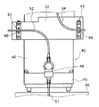
このような定量袋詰装置10に添加物を供給する微量添加装置40は、全体が圧力容器になっており、上端部に気密ホッパー42が設けられ、その下部に複数の攪拌翼43が装着された攪拌軸44が配置されている添加物貯留部41と、この添加物貯留部41の下方に、スクリューフィーダー46を有する添加物移送部45と、その下流の分散室48とが設けられている。
また、微量添加装置40は、その総重量を測定することにより、添加物の添加量を知見するための、秤量装置70に載置されている。
【0019】
スクリューフィーダー46で移送された栄養物質粉末等の添加物は、スクリューフィーダー46の終端と分散羽根47の間のスペースに充満し、さらにスクリューフィーダー46で移送される添加物によって分散羽根47の隙間から押し出され、分散されて分散室48に送出される。
【0020】
ここで、分散羽根47は、図3に示すように、円板に放射状に隙間が形成されたものである。そのため、スクリューフィーダー46の終端と分散羽根47の間のスペースに充満した添加物は、さらにスクリューフィーダー46で移送される後続の添加物の圧力によって分散羽根47の隙間から徐々に押し出されるので、スクリューフィーダーにつきものの脈動的な供給を防止して添加物を安定して定量ずつ押し出し、分散室48に送出することができる。
【0021】
分散室48に送出された添加物は、分散室48内を図2に示す矢印のように上から下に流れる圧縮空気の気流によって気流の中に分散し、この気流と共に、供給管51を通って定量袋詰装置10の連結部13に設けられた添加物供給口53から連結部13内の小麦粉に添加される。
【0022】
コンプレッサ55からの圧縮空気は、給気管50から分岐する給気管52およびに給気管54によって、分散室48および気密ホッパ42に供給される。また、供給管51は、前記圧縮空気と添加物との混合気流を分散室48から連結部13に設けられた添加物供給口53まで送る管路である。なお、図中のPは、気密ホッパー42やコンプレッサ55の内圧を図る圧力計である。
図示例においては、給気管52および給気管54に設けられたバルブ52aおよび54aによって、気密ホッパー42内の圧力と分散室48内の圧力とのバランスが維持される。ここで、気密ホッパー42と分散室48の内圧は、添加物の逆流を防止するために、同じか、気密ホッパー42の方を若干高くするのが好ましい。
【0023】
スクリューフィーダー46は、駆動モーター(図示省略)の回転軸に固定された伝達手段56に連結された伝導手段57によって定量袋詰装置10のスクリューフィーダー30と同じタイミングで回転し、これにより、小麦粉の供給量に比例した量の添加物を添加物供給口53から連結部13の小麦粉に添加する。また、攪拌翼43が装着された攪拌軸44も伝達手段56に連結された伝導手段58によって同様に回転して気密ホッパー42内の添加物のブリッジの形成を防止する。
【0024】
このようにして連結部13の小麦粉に添加された添加物は、添加物供給口53の口元の小麦粉のみに添加されるが、その後、スクリューフィーダー30によって小麦粉が攪拌混合され、均一に混合されて移送袋詰部12の充填口31から包装袋33に充填されるので、包装袋33の全ての部分で添加物が均一に混合された小麦粉を得ることができる。
【0025】
この微量添加装置40は、全体が秤量装置70に載せられており、少なくとも小麦粉を1個の包装袋33に充填する毎に、添加物を含む微量添加装置40の総重量を測定して、小麦粉に添加されて消費した添加物の重量を微量添加装置40の総重量の減少として測定している。そして、包装袋33に小麦粉を充填する度に、この包装袋の小麦粉に添加された添加物の量を測定して、表示および記録の少なくとも一方を行う。
なお、添付物の供給される量の増減は、微量添加装置40のスクリューフィーダー46の回転数を増減することによって行なわれる。
【0026】
図4に示されるように、微量添加装置40の分散室48の上部には給気管52が、分散室48の下部には供給管51が、それぞれ接続される。また、図1に示されるように、給気管54は、気密ホッパー42の頂部に接続される。
【0027】
微量添加装置40は、分散室48に供給管51および給気管52が接続され、さらに、気密ホッパー42の頂部に給気管54が接続される。また、伝達手段56を有する駆動モーターによってスクリューフィーダー46および攪拌軸44が回転される。従って、微量添加装置40には、少なくとも、供給管51、給気管52および給気管54の各配管、および駆動モーターを電源に接続する電気ケーブルが外部に接続されている。
これらの配管には、網入りビニールチューブ等の比較的高い弾性反発力を有する可撓性の耐圧ホースが使用されており、他方、電気ケーブルには、ビニールキャブタイヤケーブル等が使用されているので、いずれも可撓性ではあるが比較的高い弾性反発力を有する。
【0028】
本発明を利用する微量添加装置40においては、これらの配管や電気ケーブル等は、後述する隔壁継手68よりも微量添加装置40側では、相互に接触しないように、かつ振動等で相互に接触したり曲率半径が変動したりしない位置に固定されている。
【0029】
すなわち、図4に示すように、給気管52はエルボを用いて分散室48の上部に、供給管51は分散室48の下部に、それぞれ相互に接触することなくかつ自然に垂下するように接続される。また、給気管54も、給気管52と同様にエルボを用いることにより、気密ホッパー42の頂部に、他の配管と接触することなくかつ自然に垂下するように接続される。
この場合には、エルボを用いることなく、給気管52や給気管54等自体の湾曲によって、これらを自然に垂下するように接続を行ってもよい。
【0030】
供給管51、給気管52および給気管54は、分散室48よりも下方において、固定手段60によって固定されている。この固定手段60は、配管(および電気ケーブル等)を十分に大きく滑らかな円弧を描いて湾曲して、水平(あるいは略水平)状態とし、この水平部分で配管を固定(保持)する。
この固定手段60は、スライドブロック61と、このスライドブロック61に螺合するねじ62、ねじ62を支持する支持ブロック63からなり、ねじ62に固定されたつまみ64を回転することによってスライドブロック61を上下(鉛直)方向に移動することが可能な移動手段65に固定されている。
【0031】
この固定手段60を上下方向に移動させる移動手段65は、微量添加装置40を載置して、収納された添加物を含む総重量を測定する秤量装置70が載置された架台66に固定された取付板67に固定されている。また、供給管51、給気管52および給気管54のそれぞれの固定手段60を通り過ぎた延長部は、隔壁継手68(図4では給気管52の隔壁継手は省略されている)によって取付板67に固定され、図1に示すように、供給管51は添加物供給口53に、給気管52および給気管54は、給気管50を介して、コンプレッサ55に接続されている。
【0032】
この固定手段60による供給管51、給気管52および給気管54等の配管、さらには、電気ケーブル等の、外部に接続される可撓体の固定は、基本的に、以下のようにして行われる。
まず、微量添加装置40から外部の装置等に接続されている全ての配管や電気ケーブル等を外して微量添加装置40のみにして秤量装置70に載置し、このときの重量を測定して、この重量をたとえばリセットしてゼロとして、このゼロを基準重量とする。
【0033】
次いで、取付調整工程を行なう。すなわち、配管や電気ケーブルを1本、微量添加装置40に接続し、前述のように垂下状態から水平状態に湾曲させて固定手段60および隔壁継手68で固定し、さらに、移動手段65によって固定手段60の位置を上下方向に移動させて、秤量装置70に表示される重量が基準重量となる位置に調整して固定する。あるいは、基準重量に応じて設定された所定範囲となる位置に調整して固定する。
最初の1本の配管等の可撓体の調節、位置固定が終了したら、同様の操作を次の配管等について行い、以下、1本ずつ順次、同様の調節、位置固定を行って、全ての可撓体を微量添加装置40に接続する。
【0034】
スクリューフィーダを用いる微量添加装置40では、粉粒体の供給量を容量で制御できるため、粉粒体の供給量は、極めて正確に制御することができる。
ところが、配管や電気ケーブル等を微量添加装置40のような被測定装置に固定すると、配管や電気ケーブルの曲げることによる弾性反発力や重量、さらには外部から配管等にかかる力や、それによる曲率の変化等(以下、これらをまとめて外乱とする)が、秤量装置70による測定結果に影響を与え、正確な重量測定を行うことができない。
特に、図示例のような微量添加装置40においては、添加物を充填した状態では総重量は十数kgを超え、また、添加物の添加量は、通常、1袋当たり10g程度であるので、外乱による僅かな測定誤差も大きな精度の低下となり、粉粒体の供給量は正確であるものの、定量袋詰装置10等による1袋ずつの袋詰作業中に、添加物の添加量を迅速かつ適正に把握することが困難である。
【0035】
これに対し、本発明においては、配管等の外部と接続される可撓体を微量添加装置40等に接続する際に、前記取付調整工程によって、固定手段60の位置を上下方向に移動させて、秤量装置70による測定値を基準重量に一致させることによって、各配管等による秤量装置70への外乱を無くす、あるいは外乱が最小となる状態とでき、その結果、外乱が秤量装置70による被測定装置の総重量測定に与える影響を、最小にすることができる。
従って、図示例のように、添加物と自重との合計が20kg以上で、1袋の袋詰に対し20g以下、例えば5gの粉粒体を添加物として供給する場合であっても、正確な微量測定装置40の総重量測定、すなわち、添加物の添加重量の測定を行うことができる。
【0036】
なお、配管や電気ケーブルは、固定手段60よりも外側(微量測定装置40に対して)で、秤量手段70を載置する架台66(取付板67)に固定される前記隔壁継手68に固定されているので、これより外側の配管等による力(外力)が、固定手段60よりも内側に影響を与えることはなく、従って、秤量手段70による測定結果に影響を与えることはない。
ただし、固定手段60によって配管等を十分にしっかりと固定でき、これよりも外側の配管等による外力がない、あるいは極めて少ない場合には、固定手段60よりも外側に隔壁継手68等を設けなくてもよい。
すなわち、本発明においては、固定手段60よりも外側の配管等を動かしても、外力が固定手段60より内側の配管等に影響を与えず、従って、秤量手段70による測定結果に影響を与えることが無い(あるいは、影響が極めて小さい)構成とすればよい。
【0037】
配管や電気ケーブルの接続順序には特に限定はないが、好ましくは、比較的高い弾性反発力を有する配管や電気ケーブルを接続した後、弾性反発力が小さい配管や電気ケーブルを接続する。
なお、配管や電気ケーブルが、固定手段を上下方向に移動しても、秤量装置70に表示される重量はがほとんど変化しない弾性反発力が小さいものである場合には、十分なたるみを与えて、任意の位置に固定してもよい。
【0038】
以上のようにして、全ての配管や電気ケーブルを接続した後、気密ホッパー42に栄養物質粉末等の添加物を充填し、秤量装置70によって微量添加装置40の総重量を測定して、以下、総重量の減量によって、供給した添加物の量を計測することができる。
【0039】
以上の例は、配管や電気ケーブルの固定手段60、および、その位置調整を行う移動手段65を、秤量装置70を載置する架台66、すなわち秤量装置70による測定に何ら重量的な負荷を与えない位置に固定しているが、本発明は、これに限定はされず、秤量装置70の上に乗っている剛体部や、この剛体部に固定される部材、さらには秤量装置70に載置された部材等に、配管や電気ケーブルの固定手段60および移動手段65、さらには配管や電気ケーブルの固定部等を配置してもよい。
この構成であっても、配管や電気ケーブルによる外力が、固定手段60よりも内側に影響を与えず、秤量手段70による測定に重量的な負荷を与えなければ、正確な重量測定を行うことができる。
【0040】
図6にその一例を示す。
図6に示される例においては、秤量装置70に載置されている微量添加装置40の気密ホッパー42に取付板72を固定して、この取付板72に、移動手段65を2つ固定し、移動手段65に固定される固定手段60によって、給気管52および給気管54を(略)水平状態にして固定している。
なお、給気管52および給気管54は、固定手段60よりも外側で、秤量装置70による測定に重量的な負荷を与えない、位置が固定の剛体部に固定されている。例えば、架台66に、上方に延在するステーを取り付け、このステーに隔壁継手等を用いて給気管52および給気管54を固定すればよい。
【0041】
図6に示される例において、給気管54の取付方法は、前述の例と同様に行えばよい。
他方、給気管52の取り付けは、給気管52を分散室48の所定の位置に取付た後、鉛直方向から水平方向に、給気管52を十分な曲率をもって湾曲させ、水平状態の位置で固定手段60で給気管52を固定する。後は同様にして、移動手段65によって固定手段60を上下動して位置調整し、秤量装置70に表示される重量が基準重量(所定範囲)となる位置として、固定する。
【0042】
本態様では、取付調整行程における移動手段65による調整時に、計量値が乱れる可能性があるが、調整を終了した後は、前述の例と同様、各配管等による秤量装置70への外乱を無くす、あるいは外乱が最小となる状態とできる。また、固定手段60より外側で隔壁継手等で固定することにより、外力が固定手段60より内側に影響を与えることがなく、従って、秤量装置70による測定に影響を与える事がないので、正確な重量測定が可能である。
【0043】
図7に、本発明の別の態様を示す。
図7に示される態様は、気密ホッパー42の外壁面に、此処から垂下する状態で取付板80を固定し、この取付板80に、配管や電気ケーブルの固定手段60および移動手段65を固定している。従って、取付板80や固定手段60等は、秤量装置70に載置された状態となっている。また、本態様においては、架台66に略L字型の固定板82を固定し、この固定板82に、隔壁継手68を用いて固定手段60よりも外側で配管等を固定している。なお、本態様においては、配管等の接続や調整は、前記図4に示される態様に準じて行えばよい。
本態様においても、取付調整行程での移動手段65による調整時に、計量値が乱れる可能性があるが、調整を終了した後は、先の例と同様に、正確な重量測定を行うことができる。
【0044】
図8に、本発明の別の態様を示す。
図8に示される態様においては、気密ホッパー42の外壁面に、此処から垂下する状態で固定板84を固定し、この固定板84に垂直に固定された縦板84aを設け、この縦板84aに隔壁継手68を用いて配管を固定する。さらに、架台66に取付板86を固定し、この取付板86に、固定手段88を保持する移動手段65を取り付ける。
ここで、図示例においては、固定手段88は、移動手段65のスライドブロック61に垂直に固定された縦板で、配管等は、この縦板である固定手段88に、隔壁継手68によって固定され、移動手段65によって縦板すなわち隔壁継手68そのものを移動して、取付調整行程における調整を行う。なお、本態様においても、配管等の接続や調整は、前記図4に示される態様に準じて行えばよい。
【0045】
本態様によれば、配管等の一部が秤量手段70に影響を与える部位に固定されるものの、前述のように、移動手段65による調整時に秤量手段70の計量値が乱れることはない。また、隔壁継手68を用いて配管等を固定手段88に固定しているので、外力が秤量装置70による重量測定に影響を与えることもない。
【0046】
図6〜図8に示される例では、気密ホッパー42に取付板72等を固定し、これに、固定手段60、移動手段65、隔壁継手68(配管等の固定部)等を固定しているが、本発明はこれに限定はされず、各種の構成が利用可能である。
例えば、気密ホッパー42に、直接、移動手段65を固定してもよく、あるいは、気密ホッパー42に取り付けられるフレーム等の剛体部に、移動手段65を固定してもよい。
【0047】
【実施例】
図9、図11および図12に、実際に粉粒体供給装置(微量添加装置)によって粉粒体を送出した場合のデータを示す。
【0048】
図9のデータは、図10に示すように、図1に示す微量添加装置40と同じ微量添加装置75から送出された添加物を配管76によって送出して収納容器77に収納し、添加物の1回ごとの送出量を収納容器77を載置した秤量装置78で測定してプロットしたグラフである。
本例は、目標値を10.5gとして、10秒で添加物を送出した例で、図7のグラフから明らかなように、微量添加装置75から送出される添加物の量は非常に安定しており、目標値10.5gの送出量に対して平均値が10.50g、標準偏差が0.28gとなっている。
【0049】
図11および図12のグラフは、同じ微量添加装置75を秤量装置に載置して、同様の粉粒体の送出を行った際に、微量添加装置75の重量を計る秤量装置による測定結果を用いて算出した送出量を示すデータであって、図11は本発明を採用した例、すなわち配管や電気ケーブルを前述のように接続した例で、図12は本発明を採用しない従来例である。
【0050】
図12に示されるように、従来の測定では、目標値10.5gの送出量に対する送出量の平均値が10.35gであり、標準偏差が1.43gとなっており、平均値は比較的高い精度で送出されているが、標準偏差は、前述の実際の送出量から算出した標準偏差の5倍強にも達している。この標準偏差の増大は、明らかに秤量装置の表示に大きな誤差が含まれていることを示している。
これに対し、本発明によれば、図11に示されるように、送出量の平均値は10.50gと目標を達成しており、しかも、標準偏差が0.89gとなっており、本発明を採用しない図12の実験例と比較すると標準偏差が6割程度となっており、改善が認められる。また、図11のグラフから明らかなように、送出量が平均値から大きく離れているのは最初の数回のみであり、これを運転開始時の過渡的な現象として除外すると、本発明を採用した場合の標準偏差がさらに小さくなることは明らかである。
【0051】
【発明の効果】
本発明は、以上のように構成されているので、比較的高い弾性反発力を有する可撓性の配管や電気ケーブルによって外部に接続された被測定装置であっても、これらによる外乱が秤量装置の測定値にほとんど変動を与えることはなく、例えば小麦粉を定量袋詰する定量袋詰装置等に微量の添加物を供給する微量添加装置等の総重量を測定する場合でも、正確な測定を行って、添加物の供給量を適正に把握することができる。
【図面の簡単な説明】
【図1】 本発明を利用する定量袋詰装置の一例の概念図を示す。
【図2】 微量添加装置の先端部を示す詳細図である。
【図3】 分散羽根の形状の1例を示す図2のA−A線矢視図である。
【図4】 可撓体の固定装置を示す図1のB−B線矢視図である。
【図5】 可撓体の固定装置の詳細を示す図4のC−C線矢視図である。
【図6】 本発明における可撓体の固定装置の別の例を示す図である。
【図7】 本発明における可撓体の固定装置の別の例を示す図である。
【図8】 本発明における可撓体の固定装置の別の例を示す図である。
【図9】 微量添加装置から送出された添加物の量を示すグラフである。
【図10】 図6の実験における実験装置の構成を示す概念図である。
【図11】 本発明にかかる計量装置の測定値を示すグラフである。
【図12】 従来の計量装置の測定値を示すグラフである。
【符号の説明】
10 定量袋詰装置
11 粉粒体貯留部
12 移送袋詰部
13 連結部
14 脚部
20 ホッパー
21 攪拌翼
22 攪拌軸
23 スクリューコンベア
24,26 伝導手段
25 駆動モーター
30 スクリューフィーダー
31 充填口
32 計量装置
33 包装袋
34 可変速モーター
35 伝導手段
36 検出手段
40 微量添加装置
41 添加物貯留部
42 気密ホッパー
43 攪拌翼
44 攪拌軸
45 添加物移送部
46 スクリューフィーダー
47 分散羽根
48 分散室
50 給気管
51 供給管
52,54 給気管
53 添加物供給口
54 給気管
55 コンプレッサ
56 伝達手段
57,58 伝導手段
60 固定手段
61 スライドブロック
62 ねじ
63 支持ブロック
64 つまみ
65 移動手段
66 架台
67,72,80,86 取付板
68 隔壁継手
70 秤量装置
75 微量添加装置
76 配管
77 収納容器
78 秤量装置
82,84 固定板[0001]
BACKGROUND OF THE INVENTION
The present invention belongs to the technical field of a calibration method of a weighing device and a granular material supply device using the calibration method of the weighing device, and in particular, a flexible pipe or an electric cable connected to the granular material supply device. Of weighing apparatus and powder that can properly measure the weight of the powder supply device, that is, the weight of the supplied powder, by eliminating the influence of the powder on the weight measurement of the powder supply device to the maximum It relates to a supply device.
[0002]
[Prior art]
As a weighing device, there is known a weighing device that measures the total weight of the device to be measured and the contents stored in the device to be measured, and uses the change in the measured total weight as the change in the weight of the content. .
In such a weighing device, piping and electric cables connected to the device under test are often connected to the outside by a flexible body, and in particular, this flexible body has a relatively high elastic repulsion force. In the case of flexible pipes and electrical cables, the apparent weight of the device under test often changes due to the elastic repulsion of the flexible pipes and electrical cables, and accurate weight measurement often fails. It was.
[0003]
For example, flour for school meals may be added with several tens of ppm to several hundreds of ppm of nutrients or the like with respect to 25 kg of large bag flour. As an example, the addition of the nutrient substance is to supply the nutrient substance to the powder-filling packaging device that fills the packaging bag with the flour using a minute-particle addition device (feed device) of the powder and granule. Is done by.
[0004]
In order to stably manufacture standard-compliant products in the manufacture of powdered products with such additives, it is necessary to properly grasp the amount of additive added to the flour. . As this method, a method of measuring the weight of the whole micro-addition apparatus including the additive during supply and grasping the added amount by reducing the weight is exemplified.
For that purpose, several kg of additives such as nutrient powders are stored in a micro-adding device (device to be measured) with a weight exceeding 20 kg, and the micro-adding device containing this additive is placed on the weighing device. Depending on the change in the total weight, it is necessary to measure the weight change of about 5 g to 10 g of the additive such as the added nutrient powder.
[0005]
However, this micro-adding device is connected to the pipes and electric cables for transporting the granular material from the outside, and these pipes and electric cables may have a large elastic repulsion. Changes in the total weight of a micro-addition device measured by a weighing device (additives) may not be able to sufficiently follow changes in several grams of additives such as nutrient powders delivered to be added to wheat flour In some cases, a large error may occur in the measurement of the amount of addition.
[0006]
Such a change in weight of 1 g or less in the weighing device is easily caused even if a slight force is applied to the micro-adding device from the outside, and the flexibility is connected to the outside from the micro-adding device. If a flexible pipe or electric cable has a certain amount of elastic repulsion, it can be easily caused by a slight change in the radius of curvature, a change in the mutual contact position, or the like.
In some cases, the variation in weight is also caused by a change in the hardness of the pipe, a change in the hardness of the covering of the electric cable, or a change in the internal pressure of the air pipe caused by a change in temperature.
[0007]
[Problems to be solved by the invention]
The present invention has been made on the basis of such knowledge. Even a device to be measured connected to the outside by a flexible pipe or an electric cable having a relatively high elastic repulsion force can be used. The influence that the flexible body has on the weight measurement result of the device to be measured can be minimized, for example, even when supplying a granular material of 20 g or less from a microscopic granular material supply device having a total weight exceeding 20 kg, A calibration method for a weighing device, which can properly measure the total weight of a microscopic particle supply device and grasp the supply amount of the granular material, and a powder supply device using the calibration method of the weighing device It is to provide.
[0008]
[Means for Solving the Problems]
In order to solve this problem, a calibration method for a weighing device according to the present invention is a measuring device connected to the outside by a flexible body and a weighing device for measuring the weight of contents stored in the measuring device. And measuring the total weight of the device to be measured in which the contents are stored, and taking the change in the measured total weight as the change in the weight of the content, from the device to be measured to the flexible body And measuring the weight of only the device to be measured by the weighing device, obtaining a reference weight of the weighing device from the measurement result, connecting the flexible body to the device to be measured, and measuring the weighing Adjusting the fixed position of the flexible body to a position where the measured value by the apparatus is within a predetermined range set according to the reference weight is performed for each flexible body, and all the flexible bodies are measured. Installation adjustment work for flexible body connected to the device Yes the doorThen, the adjustment of the fixing position of the flexible body in the attachment adjusting step is performed by using fixing means for holding the flexible body in a substantially horizontal state and moving the fixing means in the vertical direction.A calibration method for a weighing apparatus is provided.
[0010]
Moreover, the granular material supply apparatus of the present invention has a transporting means for transporting the granular material by a screw feeder and a transporting means for pneumatically transporting the granular material conveyed by the transporting means. The substantially horizontal state in which the connected powder body supply means, the weighing means for measuring the weight of the powder body supply means, and the flexible body connected to the powder body supply means are fixed in a substantially horizontal state. Fixing means that can adjust the position of the flexible body in the vertical direction, and adjusting the vertical position of the fixing means to reduce the influence of the flexible body on the weighing means. A granular material supply apparatus is provided.
[0011]
The powder supply means preferably supplies an additive added to the powder packed in the powder filling and packaging apparatus to the powder filling and packaging apparatus. The powder supply means has a total weight of more than 20 kg with its own weight and the total filling amount of the granular material, and 20 g or less of the granular material with respect to one bag packed by the granular material filling and packaging apparatus. The body is preferably supplied as an additive, and the fixing means is preferably configured to bend the flexible body extending in the vertical direction and hold it in a substantially horizontal state.
[0012]
DETAILED DESCRIPTION OF THE INVENTION
Hereinafter, a calibration method for a weighing device and a powder and particle supply device according to the present invention will be described with reference to the drawings.
FIG. 1 shows a filling and packaging machine in which a microscopic addition device to which the present invention is suitably applied is placed on a weighing device. On the left side of the figure is a
[0013]
The fixed-
In addition, an
[0014]
The powder
[0015]
On the other hand, a
[0016]
The
[0017]
The
[0018]
The
In addition, the
[0019]
The additive such as nutrient powder transferred by the
[0020]
Here, as shown in FIG. 3, the
[0021]
The additive delivered to the
[0022]
Compressed air from the
In the illustrated example, the balance between the pressure in the
[0023]
The
[0024]
The additive added to the flour of the connecting
[0025]
The
In addition, increase / decrease in the quantity supplied of an attachment is performed by increasing / decreasing the rotation speed of the
[0026]
As shown in FIG. 4, an
[0027]
In the minute
For these pipes, flexible pressure-resistant hoses with relatively high elastic repulsion, such as netted vinyl tubes, are used. On the other hand, vinyl cabtyre cables are used for electrical cables. , Both of which are flexible but have a relatively high elastic repulsion.
[0028]
In the
[0029]
That is, as shown in FIG. 4, the
In this case, without using an elbow, the connection may be made so that they are naturally suspended by the curvature of the
[0030]
The
The fixing means 60 includes a
[0031]
The moving means 65 for moving the fixing means 60 in the vertical direction is fixed to a
[0032]
The fixing of the flexible body connected to the outside such as the
First, remove all the pipes and electrical cables connected to the external device etc. from the
[0033]
Next, an attachment adjustment process is performed. That is, one pipe or electric cable is connected to the
When the adjustment and position fixing of the flexible body such as the first pipe is completed, the same operation is performed on the next pipe and the like, and then the same adjustment and position fixing are sequentially performed one by one. The flexible body is connected to the
[0034]
In the
However, when a pipe or an electric cable is fixed to a device to be measured such as the
In particular, in the
[0035]
On the other hand, in the present invention, when the flexible body connected to the outside such as piping is connected to the
Therefore, as shown in the illustrated example, the total of the additive and the own weight is 20 kg or more, and even when supplying 20 g or less, for example, 5 g of granular material as an additive to one bag, it is accurate. The total weight measurement of the
[0036]
The pipe and the electric cable are fixed to the bulkhead joint 68 fixed to the frame 66 (mounting plate 67) on which the weighing
However, if the fixing means 60 can fix the pipes and the like sufficiently and there is no external force due to the outer pipes or the like, or if there is very little external force, the partition joint 68 or the like is not provided outside the fixing means 60. Also good.
That is, in the present invention, even if a pipe or the like outside the fixing means 60 is moved, the external force does not affect the pipe or the like inside the fixing means 60, and therefore the measurement result by the weighing
[0037]
There is no particular limitation on the connection order of the piping and the electric cable, but preferably, after connecting the piping and the electric cable having a relatively high elastic repulsion force, the piping and the electric cable having a small elastic repulsion force are connected.
If the elastic repulsive force is small enough that the weight displayed on the weighing
[0038]
After connecting all the pipes and electrical cables as described above, the
[0039]
In the above example, the fixing means 60 for piping and electric cables and the moving means 65 for adjusting the position of the weighing
Even in this configuration, an accurate weight measurement can be performed as long as the external force due to the piping or the electric cable does not affect the inside of the fixing means 60 and does not give a heavy load to the measurement by the weighing
[0040]
An example is shown in FIG.
In the example shown in FIG. 6, the mounting
The
[0041]
In the example shown in FIG. 6, the method of attaching the
On the other hand, the
[0042]
In this aspect, there is a possibility that the measurement value is disturbed during the adjustment by the moving means 65 in the attachment adjustment process. However, after the adjustment is completed, the disturbance to the weighing
[0043]
FIG. 7 shows another embodiment of the present invention.
In the embodiment shown in FIG. 7, a mounting
Also in this aspect, there is a possibility that the measurement value is disturbed during the adjustment by the moving means 65 in the attachment adjustment process. However, after the adjustment is completed, an accurate weight measurement can be performed as in the previous example. .
[0044]
FIG. 8 shows another embodiment of the present invention.
In the embodiment shown in FIG. 8, a fixing
Here, in the illustrated example, the fixing means 88 is a vertical plate fixed vertically to the
[0045]
According to this aspect, although a part of the piping or the like is fixed to a portion that affects the weighing
[0046]
In the example shown in FIGS. 6 to 8, the mounting
For example, the moving means 65 may be fixed directly to the
[0047]
【Example】
FIG. 9, FIG. 11 and FIG. 12 show data when the granular material is actually sent out by the granular material supply device (trace addition device).
[0048]
As shown in FIG. 10, the data in FIG. 9 is obtained by sending the additive sent from the
In this example, the target value is 10.5 g, and the additive is delivered in 10 seconds. As is apparent from the graph of FIG. 7, the amount of additive delivered from the micro-adder 75 is very stable. The average value is 10.50 g and the standard deviation is 0.28 g with respect to the delivery amount of the target value 10.5 g.
[0049]
The graphs of FIGS. 11 and 12 show the measurement results obtained by the weighing device that measures the weight of the
[0050]
As shown in FIG. 12, in the conventional measurement, the average value of the delivery amount with respect to the delivery amount of the target value 10.5 g is 10.35 g, the standard deviation is 1.43 g, and the average value is relatively Although it is transmitted with high accuracy, the standard deviation is the actual transmission described above.QuantityIt has reached 5 times the standard deviation calculated. This increase in standard deviation clearly indicates that the weighing device display contains a large error.
On the other hand, according to the present invention, as shown in FIG. 11, the average value of the delivery amount is 10.50 g, achieving the target, and the standard deviation is 0.89 g. Compared with the experimental example of FIG. Further, as is apparent from the graph of FIG. 11, the delivery amount is far from the average value only in the first few times, and the present invention is adopted if this is excluded as a transient phenomenon at the start of operation. Obviously, the standard deviation in this case is even smaller.
[0051]
【The invention's effect】
Since the present invention is configured as described above, even if the device to be measured is connected to the outside by a flexible pipe or electric cable having a relatively high elastic repulsion force, the disturbance due to these is a weighing device. For example, when measuring the total weight of a trace addition device that supplies a trace amount of additive to a quantitative bagging device that quantitatively packs flour, etc. Thus, it is possible to properly grasp the supply amount of the additive.
[Brief description of the drawings]
FIG. 1 shows a conceptual diagram of an example of a fixed-quantity bagging apparatus using the present invention.
FIG. 2 is a detailed view showing a tip portion of the trace addition device.
FIG. 3 is a view taken along the line AA in FIG. 2 showing an example of the shape of the dispersion blade.
4 is a view taken along the line B-B in FIG. 1 showing a fixing device for a flexible body.
5 is a cross-sectional view taken along the line CC of FIG. 4 showing details of the flexible body fixing device.
FIG. 6 is a view showing another example of a flexible body fixing device according to the present invention.
FIG. 7 is a view showing another example of the flexible body fixing device according to the present invention.
FIG. 8 is a diagram showing another example of a flexible body fixing device according to the present invention.
FIG. 9 is a graph showing the amount of additive delivered from the micro-adder.
10 is a conceptual diagram showing a configuration of an experimental apparatus in the experiment of FIG.
FIG. 11 is a graph showing measured values of the weighing device according to the present invention.
FIG. 12 is a graph showing measured values of a conventional weighing device.
[Explanation of symbols]
10 Fixed-quantity bagging equipment
11 Powder storage part
12 Transfer bagging part
13 Connecting part
14 legs
20 Hopper
21 Stirring blade
22 Stirring shaft
23 Screw conveyor
24,26 Conducting means
25 Drive motor
30 Screw feeder
31 Filling port
32 Weighing device
33 Packaging bags
34 Variable speed motor
35 Conducting means
36 Detection means
40 Trace addition equipment
41 Additive reservoir
42 Airtight hopper
43 Stirring blade
44 Stirring shaft
45 Additive transfer section
46 Screw feeder
47 Dispersion blade
48 Dispersion chamber
50 Air supply pipe
51 Supply pipe
52,54 Air supply pipe
53 Additive supply port
54 Air supply pipe
55 Compressor
56 Transmission means
57, 58 Conducting means
60 Fixing means
61 slide block
62 screw
63 Support block
64 knobs
65 Moving means
66 frame
67, 72, 80, 86 Mounting plate
68 Bulkhead joint
70 Weighing device
75 Trace addition device
76 Piping
77 Storage container
78 Weighing device
82,84 fixed plate
Claims (5)
前記被測定装置から前記可撓体を全て外して、前記秤量装置によって前記被測定装置のみの重量を測定し、この測定結果から前記秤量装置の基準重量を得る工程と、
前記可撓体を前記被測定装置に接続し、前記秤量装置による測定値が前記基準重量に応じて設定された所定範囲内となる位置に前記可撓体の固定位置を調整することを、可撓体1本ずつ行い、全ての可撓体を被測定装置に接続する、可撓体の取付調整工程とを有し、
前記取付調整工程における可撓体の固定位置の調整を、前記可撓体をほぼ水平状態として保持する固定手段を用い、この固定手段を鉛直方向に移動することによって行うことを特徴とする秤量装置の校正方法。A measuring device connected to the outside by a flexible body and a weighing device for measuring the weight of the contents stored in the measuring device, and measuring the total weight of the measuring device in which the contents are stored In a weighing device in which the change in the measured total weight is the change in the weight of the contents,
Removing all of the flexible body from the device to be measured, measuring the weight of only the device to be measured by the weighing device, and obtaining a reference weight of the weighing device from the measurement result;
It is possible to connect the flexible body to the device to be measured and adjust the fixed position of the flexible body to a position where a measurement value by the weighing device is within a predetermined range set according to the reference weight. They performed one by one Shiwakarada, connecting all of the flexure to the device under test, possess a mounting adjustment step of the flexible member,
The weighing apparatus is characterized in that the fixing position of the flexible body in the attachment adjusting step is adjusted by using a fixing means for holding the flexible body in a substantially horizontal state and moving the fixing means in the vertical direction. Calibration method.
前記固定手段の鉛直方向の位置を調整することにより、前記可撓体による秤量手段への影響を低減することを特徴とする粉粒体供給装置。A powder supply means having a transfer means for transferring powder particles by a screw feeder, and a transport means for pneumatically transporting the powder particles conveyed by the transfer means, and connected to the outside by a flexible body; Weighing means for measuring the weight of the granule supply means and the flexible body connected to the powder supply means are fixed in a substantially horizontal state, and the position of the flexible body in the substantially horizontal state is adjustable in the vertical direction. Fixing means,
By adjusting the position of the fixing means in the vertical direction, the influence of the flexible body on the weighing means is reduced.
Priority Applications (1)
| Application Number | Priority Date | Filing Date | Title |
|---|---|---|---|
| JP02387899A JP3881123B2 (en) | 1998-11-27 | 1999-02-01 | Weighing device calibration method and granular material supply device |
Applications Claiming Priority (3)
| Application Number | Priority Date | Filing Date | Title |
|---|---|---|---|
| JP10-336762 | 1998-11-27 | ||
| JP33676298 | 1998-11-27 | ||
| JP02387899A JP3881123B2 (en) | 1998-11-27 | 1999-02-01 | Weighing device calibration method and granular material supply device |
Publications (3)
| Publication Number | Publication Date |
|---|---|
| JP2000221075A JP2000221075A (en) | 2000-08-11 |
| JP2000221075A5 JP2000221075A5 (en) | 2005-10-27 |
| JP3881123B2 true JP3881123B2 (en) | 2007-02-14 |
Family
ID=26361311
Family Applications (1)
| Application Number | Title | Priority Date | Filing Date |
|---|---|---|---|
| JP02387899A Expired - Fee Related JP3881123B2 (en) | 1998-11-27 | 1999-02-01 | Weighing device calibration method and granular material supply device |
Country Status (1)
| Country | Link |
|---|---|
| JP (1) | JP3881123B2 (en) |
Families Citing this family (3)
| Publication number | Priority date | Publication date | Assignee | Title |
|---|---|---|---|---|
| CN102700956A (en) * | 2012-05-26 | 2012-10-03 | 无锡市华星电力环保修造有限公司 | Activated charcoal measuring and feeding device |
| CN114259934B (en) * | 2021-11-15 | 2022-09-13 | 湖南中联重科新材料科技有限公司 | Powder mixing dedusting method and system |
| JP7199138B1 (en) * | 2022-10-13 | 2023-01-05 | 株式会社エー・アンド・デイ | electronic balance |
-
1999
- 1999-02-01 JP JP02387899A patent/JP3881123B2/en not_active Expired - Fee Related
Also Published As
| Publication number | Publication date |
|---|---|
| JP2000221075A (en) | 2000-08-11 |
Similar Documents
| Publication | Publication Date | Title |
|---|---|---|
| JP2984059B2 (en) | Method and apparatus for bagging bulk material with a predetermined filling volume | |
| KR0143227B1 (en) | Device and process for monitoring material flow, and use of the process | |
| US8710379B2 (en) | Check weigher comprising of a rotating weighing chute with an accumulating and a discharge position that calculates flow rate by measuring weight accumulated during a predetermined time interval | |
| JPH047453B2 (en) | ||
| JP2009540323A (en) | Balance weight type dispensing system | |
| EP0544798A4 (en) | ||
| US20060213153A1 (en) | Device and system for modified atmosphere packaging | |
| JP3881123B2 (en) | Weighing device calibration method and granular material supply device | |
| CN1761860A (en) | Device for effecting continuous gravimetric dosing | |
| US5007561A (en) | Non-flooding set rate feeder | |
| CN202382833U (en) | Speed governing metering screw weighing device | |
| US20200048007A1 (en) | Feeder | |
| US6814108B1 (en) | Precision filling apparatus | |
| JPH11108742A (en) | Air slide type conveyor scale | |
| MXPA04012354A (en) | Loss-in-weight feeder with discharge pressure compensator. | |
| JP2008517256A (en) | Weighing device for bulk products | |
| AU618246B2 (en) | Non-flooding set rate feeder | |
| CN215797187U (en) | A carry measurement belt for compound fertilizer production | |
| JP4275779B2 (en) | Filling and packing machine for powder and granule with a small amount of addition equipment | |
| JP2007322143A (en) | Weighing feeding device for powder granular material | |
| JP2991539B2 (en) | A device for adding trace substances to powders | |
| CN220577547U (en) | Metering device for rice processing | |
| JP2000221075A5 (en) | ||
| CN219821807U (en) | High-precision quick metering device | |
| CN207248309U (en) | A kind of belt conveyer scale of automatic feeding system |
Legal Events
| Date | Code | Title | Description |
|---|---|---|---|
| A521 | Written amendment |
Free format text: JAPANESE INTERMEDIATE CODE: A523 Effective date: 20050728 |
|
| A621 | Written request for application examination |
Free format text: JAPANESE INTERMEDIATE CODE: A621 Effective date: 20050728 |
|
| A977 | Report on retrieval |
Free format text: JAPANESE INTERMEDIATE CODE: A971007 Effective date: 20060801 |
|
| A131 | Notification of reasons for refusal |
Free format text: JAPANESE INTERMEDIATE CODE: A131 Effective date: 20060815 |
|
| A521 | Written amendment |
Free format text: JAPANESE INTERMEDIATE CODE: A523 Effective date: 20061005 |
|
| TRDD | Decision of grant or rejection written | ||
| A01 | Written decision to grant a patent or to grant a registration (utility model) |
Free format text: JAPANESE INTERMEDIATE CODE: A01 Effective date: 20061031 |
|
| A61 | First payment of annual fees (during grant procedure) |
Free format text: JAPANESE INTERMEDIATE CODE: A61 Effective date: 20061109 |
|
| R150 | Certificate of patent or registration of utility model |
Free format text: JAPANESE INTERMEDIATE CODE: R150 |
|
| FPAY | Renewal fee payment (event date is renewal date of database) |
Free format text: PAYMENT UNTIL: 20101117 Year of fee payment: 4 |
|
| FPAY | Renewal fee payment (event date is renewal date of database) |
Free format text: PAYMENT UNTIL: 20111117 Year of fee payment: 5 |
|
| FPAY | Renewal fee payment (event date is renewal date of database) |
Free format text: PAYMENT UNTIL: 20121117 Year of fee payment: 6 |
|
| FPAY | Renewal fee payment (event date is renewal date of database) |
Free format text: PAYMENT UNTIL: 20121117 Year of fee payment: 6 |
|
| FPAY | Renewal fee payment (event date is renewal date of database) |
Free format text: PAYMENT UNTIL: 20131117 Year of fee payment: 7 |
|
| R250 | Receipt of annual fees |
Free format text: JAPANESE INTERMEDIATE CODE: R250 |
|
| R250 | Receipt of annual fees |
Free format text: JAPANESE INTERMEDIATE CODE: R250 |
|
| R250 | Receipt of annual fees |
Free format text: JAPANESE INTERMEDIATE CODE: R250 |
|
| R250 | Receipt of annual fees |
Free format text: JAPANESE INTERMEDIATE CODE: R250 |
|
| R250 | Receipt of annual fees |
Free format text: JAPANESE INTERMEDIATE CODE: R250 |
|
| LAPS | Cancellation because of no payment of annual fees |