JP3879570B2 - Mobile phone - Google Patents
Mobile phone Download PDFInfo
- Publication number
- JP3879570B2 JP3879570B2 JP2002110186A JP2002110186A JP3879570B2 JP 3879570 B2 JP3879570 B2 JP 3879570B2 JP 2002110186 A JP2002110186 A JP 2002110186A JP 2002110186 A JP2002110186 A JP 2002110186A JP 3879570 B2 JP3879570 B2 JP 3879570B2
- Authority
- JP
- Japan
- Prior art keywords
- antenna
- mobile phone
- electrode terminal
- groove
- positive electrode
- Prior art date
- Legal status (The legal status is an assumption and is not a legal conclusion. Google has not performed a legal analysis and makes no representation as to the accuracy of the status listed.)
- Expired - Fee Related
Links
Images


Landscapes
- Emergency Alarm Devices (AREA)
- Telephone Set Structure (AREA)
- Telephone Function (AREA)
- Telephonic Communication Services (AREA)
Description
【0001】
【発明の属する技術分野】
本発明は、緊急通報機能を付加した携帯電話機に関するものである。
【0002】
【従来の技術】
従来、緊急通報機能を付加した携帯電話機には、使用者より緊急入力があった際に、その緊急入力信号を検出して自動的に警報音を鳴音し、あるいは同時に自動的に発呼を行うことで、使用者が緊急事態の意思表示を行うことができるようにした携帯電話機が提案されている(特開平11−164057号)。
【0003】
すなわち、それは、図7(a)に携帯電話機のブロック図で示したように、携帯電話機101は、緊急入力手段102によって入力された緊急入力を緊急入力検出手段103によって検出し、検出結果を中央制御装置104に伝達する。中央制御装置104は、緊急入力があった場合にサウンダ105を制御して自動的に警報106を鳴音させるか、あるいは同時に無線機107を制御して自動的に発呼108を行う。ここで緊急入力検出手段103は、図7(b)の緊急入力検出手段のブロック図で示したように、ストラップ204を引き抜くことにより緊急入力できるようにしたものである。
【0004】
【発明が解決しようとする課題】
このようなストラップを引き抜くことによって緊急入力できるようにしてある緊急通報機能付き携帯電話機においては、ストラップが簡単に取り外しし易いものなので誤動作を起こしやすく、また緊急咄嗟時の動転時には特にお年寄りや子供、女性にとって取扱い難いという問題があった。
【0005】
中には、必要がないとか、有るとかえって煩わしいとかでストラップを付けない人もいるのが実状である。
【0006】
そこで、本発明が解決しようとする課題は、携帯電話機で、緊急事態に特にお年寄りや子供、女性にとって極めて容易に危険を知らせることのできる緊急通報機能付き携帯電話機を提案することにある。
【0007】
【課題を解決するための手段】
この課題を解決するために本発明は、アンテナ1が一定以上の力で引っ張られると、アンテナ1の下部先端に取り付けられたアンテナ電極2がアンテナ1から外れてアンテナ収納溝3の底部9に落下し、底部9に設けられたプラス電極端子4とマイナス電極端子5の両電極に接触して警報発信装置6の回路を閉じて、前記警報発信装置6が緊急通報信号を発信する構成からなる携帯電話機であって、前記アンテナ電極2は、金属ストッパー7に当たったときにアンテナ電極2の先端の上部にはめられた反発性部材8によって、アンテナ溝底部9へはじき飛ばされる構成、または、金属ストッパー7の先端に取り付けられた反発性部材8に当たってはじき飛ばされる構成からなり、前記アンテナ収納溝底部9は、底にマイナス電極端子5を埋め込まれたベース11と溝部3の側面に取り付けられたプラス電極端子4とからなり、プラス電極端子4に戻り防止用の爪4aを設けた構成、または、溝部3の側面に取り付けられたマイナス電極端子5およびプラス電極端子4とからなり、それぞれ電極端子5,4に戻り防止用のふくらみ5b、4bを設けた構成の携帯電話機である。さらに前記警報発信装置6からの発信信号を、携帯電話機の短縮ダイアルの第1番目に指定した緊急通報番号の信号か、または、携帯電話機に組込まれたブザーをならす信号とする携帯電話機である。
【0008】
【発明の実施の形態】
本発明の請求項1に記載の携帯電話機は、アンテナが一定以上の力で引っ張られると、アンテナの下部先端に取り付けられたアンテナ電極がアンテナから外れてアンテナ収納溝の底部に落下し、底部に設けられたプラス電極端子とマイナス電極端子の両電極に接触して警報発信装置の回路を閉じ、前記警報発信装置が緊急通報信号を発信するように構成されているので、緊急時アンテナを引っ張るだけの簡単な操作で、誰でも容易に急を知らせることができるという作用効果を有する。
【0009】
また、請求項2及び3に記載の携帯電話機は、前記アンテナ電極が、金属ストッパーに当たったときにアンテナ電極の先端の上部にはめられた反発性部材によって、アンテナ溝の底部へはじき飛ばされるように構成されている、または、前記アンテナ電極が、金属ストッパーの先端に取り付けられた反発性部材に当たってはじき飛ばされるように構成されているので、共にアンテナ電極を急速確実に底部へ到達させる作用効果を発揮するが、特に後者ではアンテナ電極の構造を簡単に製作できるという作用効果がある。
【0010】
また、請求項4および5に記載の携帯電話機は、前記アンテナ収納溝の底部が、底にマイナス電極端子を埋め込まれたベースと溝部の側面に取り付けられたプラス電極端子とからなり、プラス電極端子に戻り防止用の爪が設けられた構成、または、前記アンテナ収納溝の底部が、溝部の側面に取り付けられたマイナス電極端子およびプラス電極端子とからなり、それぞれ電極端子に戻り防止用のふくらみが設けられた構成になっているので、共にアンテナ電極が底部に当たった反動で溝の上部へ戻らないようにストッパーでアンテナ電極を確実にキャッチして回路をスイッチするという作用効果を有するが、特に後者ではキャッチングを強化できるという作用効果がある。
【0011】
また、請求項6に記載の携帯電話機は、前記警報発信装置の回路を閉じて発信される発信信号が、携帯電話機の短縮ダイアルの第1番目に指定した緊急通報番号の信号としたものであるから、希望の緊急連絡先にいち早く連絡でき、また持ち主が日ごろから一番に連絡のとりたい相手に自動的に連絡できるという作用効果を有する。
【0012】
また、請求項7に記載の携帯電話機は、前記警報発信装置の回路を閉じて発信される発信信号が、携帯電話機に組込まれたブザーをならす信号としたものであるから、緊急警報をその場で発して周りの人々へ異常を通知し助けを求めることができるという作用効果を有する。
【0013】
以下、本発明の実施の形態について、図1から図6を用いて詳しく説明する。
【0014】
(実施の形態1)
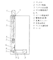
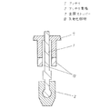
図1は、本発明の一実施の形態による携帯電話機で、裏蓋を外した内部のアンテナ部のみを示す平面図、図2は、同アンテナ電極周囲を示す断面図で、図3は、同アンテナ溝底部における爪部の拡大断面図である。
【0015】
図1において、1はアンテナ、2はアンテナ電極、3はアンテナ収納溝、4はプラス電極端子、4aはプラス電極端子に設けた爪、5はマイナス電極端子、6は警報発信装置、7は金属ストッパー、8は反発性部材、9はアンテナ溝底部、11はベースであって、アンテナ1が一定以上の力で引っ張られると、アンテナ1の下部先端に取り付けられたアンテナ電極2がアンテナ1から外れてアンテナ収納溝3の底部9に落下し、底部9に設けられたプラス電極端子4とマイナス電極端子5の両電極に接触して警報発信装置6を閉じて緊急通報信号を発信するように構成した携帯電話機であって、前記アンテナ電極2は、金属ストッパー7に当たったときにアンテナ電極2の先端の上部にはめられた反発性部材8ではじき飛ばされるように構成された携帯電話機である。
【0016】
ここで、アンテナ電極2の周囲は、図2の拡大断面図に示すように、通常使用のアンテナ1の伸縮操作では簡単に外れないように、溝内部のアンテナ1の先端には球状の膨らみを設けて、それがアンテナ電極2の凹み部に填め込まれた状態になっている。そして、アンテナ電極2の上部のアンテナ1の周辺にはバネ性を有する反発性部材8が填め込まれて載っている。
【0017】
今、アンテナ1が一定以上の力、例えば約30N以上の力で引き抜かれると、反発性部材8がアンテナ1を携帯電話機ケースに止めてある支持部に取り付けられている金属ストッパー7の先端に当たって反発性部材8が圧縮されその反発力でアンテナ電極2が外れて飛ばされる。
【0018】
飛ばされたアンテナ電極2は、アンテナ溝底部9に到達し、図3に拡大断面図で示したように、アンテナ収納溝3の底部9にマイナス電極端子5を埋め込まれたベース11と溝部3の側面に取り付けられたプラス電極端子4との間に収まり(点線で示す)、プラス電極端子4に設けられた戻り防止用の爪4aでストップし元へ戻らない構成としたものである。
【0019】
次に、図4は、本発明の携帯電話機を利用した緊急通報の方法を説明する為の裏蓋を外した内部の図であって、(a)は、アンテナ1の格納状態の平面図、(b)は、アンテナ1を引き抜き直後のアンテナ電極2の位置を示す平面図、(c)は、引き抜いた後の平面図で、アンテナ電極2がアンテナ収納溝3の底部9に落下した状態の平面図である。
【0020】
尚、本実施の形態で示した図2のようなバネによる反発性部材8の代わりに、図5に拡大断面図で示したように、金属ストッパー7の先端にゴムのような反発性部材10を取り付けておいてもよい。
【0021】
また、マイナス電極端子5およびプラス電極端子4は、図6に断面図で示すように、アンテナ溝底部9の周辺壁に設けて、それらの端部近くに一対の膨らみ4bと5bを設けて、はじき飛ばされてきたアンテナ電極2が再び飛び出さないように閉じこめかつ両電極4,5に完全接触できる構造でもよい。
【0022】
ところで、緊急発信装置6の発信信号を、携帯電話機の短縮ダイアルの第1番目に指定した緊急通報番号の信号である構成とした。こうしておけば、希望の緊急連絡先にいち早く連絡でき、また持ち主が日ごろから一番に連絡のとりたい相手に自動的に連絡できるので、一早く異常を察知してもらえて危機脱出を早められる。もちろん、第1番目に指定する緊急通報番号を、警察110番、救急119番または警備会社番号など自分が第1に緊急通報をしたい電話先としてもよく、さらには、発信装置の発信信号で警報ブザーを鳴らしたり警報ランプを点灯するようにして、即身近に知らせても良い。
【0023】
なお、一端外れたアンテナ電極は、再びアンテナの先端に嵌め込んでまた使用することができる。
【0024】
【発明の効果】
以上のように本発明の携帯電話機は、アンテナが一定以上の力で引っ張られると、アンテナの下部先端に取り付けられたアンテナ電極がアンテナから外れてアンテナ収納溝の底部に落下し、底部に設けられたプラス電極端子とマイナス電極端子の両電極に接触して警報発信装置の回路を閉じ、前記警報発信装置が緊急通報信号を発信する構成になっており、更にその発信信号は、携帯電話機の短縮ダイアルの第1番目に指定した緊急通報番号の信号、あるいは携帯電話機に組込まれたブザーをならす信号としたものであるから、
(1)緊急時アンテナを引っ張るだけの極めて簡単な操作で、特にキー操作やスイッチ操作の不得手な老人子供また女性達でも、咄嗟時に素早く急を知らせることができる。
(2)持ち主が日ごろ一番に連絡のとりたい相手に自動的に連絡できる。
(3)ブザーも鳴らせばその場で周りに通知し助けを求めることができる。
(4)アンテナバーを引っ張るという突飛な発明であるが、バー状で引っ張りたくなる人間の心理をうまく活用していて普及しやすい。
(5)アンテナを引っ張った携帯電話機を気づかれないように犯人の所持品や車の中にこっそり忍ばせたり、放り込んだりすれば、その携帯電話機が逆探知機の役割をして、犯人逮捕を早める可能性もあり、昨今必要性の増す個人の安全対策に有効であるなど我々にとって極めて有用な発明である。
【図面の簡単な説明】
【図1】本発明の一実施の形態による携帯電話機で、裏蓋を外した内部のアンテナ部を示す平面図
【図2】同、アンテナ電極周囲を示す断面図
【図3】同、アンテナ溝底部における爪部の拡大断面図
【図4】同、緊急通報時前後のアンテナ部内の状態説明図で、
(a)は、アンテナ格納状態の平面図
(b)は、アンテナを引き抜き直後のアンテナ電極の位置を示す平面図
(c)は、アンテナを引き抜いた後、アンテナ電極がアンテナ収納溝の底部に落下した状態の平面図
【図5】同、アンテナ金属ストッパー部の拡大断面図
【図6】同、アンテナ溝底部におけるふくらみ部の拡大説明図
【図7】(a)は、従来の緊急通報機能付き携帯電話機におけるブロック図
(b)は、同、緊急入力検出手段のブロック図
【符号の説明】
1 アンテナ
2 アンテナ電極
3 アンテナ収納溝
4 プラス電極端子
4a 爪
5 マイナス電極端子
6 警報発信装置
7 金属ストッパー
8 反発性部材
9 アンテナ溝底部
11 ベース[0001]
BACKGROUND OF THE INVENTION
The present invention relates to a mobile phone to which an emergency call function is added.
[0002]
[Prior art]
Conventionally, when an emergency input is made by a user, a mobile phone with an emergency call function detects the emergency input signal and automatically sounds an alarm sound, or automatically makes a call at the same time. There has been proposed a cellular phone that allows a user to display an intention of an emergency situation (Japanese Patent Laid-Open No. 11-164057).
[0003]
That is, as shown in the block diagram of the mobile phone in FIG. 7A, the mobile phone 101 detects the emergency input input by the emergency input means 102 by the emergency input detection means 103, and the detection result is displayed in the center. This is transmitted to the
[0004]
[Problems to be solved by the invention]
In such a mobile phone with an emergency call function that allows emergency input by pulling out the strap, the strap is easy to remove, so it is easy to cause a malfunction. There was a problem that it was difficult for women to handle.
[0005]
Some people don't attach straps because they are not necessary or are bothersome.
[0006]
Therefore, the problem to be solved by the present invention is to propose a mobile phone with an emergency call function that can be used to notify a person of danger in an emergency situation particularly easily for the elderly, children and women.
[0007]
[Means for Solving the Problems]
In order to solve this problem, according to the present invention, when the
[0008]
DETAILED DESCRIPTION OF THE INVENTION
In the mobile phone according to
[0009]
The cellular phone according to
[0010]
According to a fourth aspect of the present invention, in the cellular phone according to the present invention, the bottom of the antenna housing groove includes a base with a negative electrode terminal embedded in the bottom and a positive electrode terminal attached to a side surface of the groove. Or a bottom portion of the antenna housing groove is composed of a negative electrode terminal and a positive electrode terminal attached to the side surface of the groove portion, and each electrode terminal has a bulge for preventing return. Since it has a provided structure, both have the effect of switching the circuit by securely catching the antenna electrode with a stopper so that the antenna electrode does not return to the top of the groove due to the reaction that hits the bottom, The latter has the effect of enhancing the catching.
[0011]
Further, in the mobile phone according to claim 6, the outgoing signal transmitted by closing the circuit of the alarm transmitter is a signal of the emergency call number designated first in the speed dial of the mobile phone. Therefore, it is possible to quickly contact a desired emergency contact and to automatically contact the person whom the owner wants to contact first.
[0012]
Further, in the mobile phone according to
[0013]
Hereinafter, embodiments of the present invention will be described in detail with reference to FIGS.
[0014]
(Embodiment 1)
FIG. 1 is a plan view showing only the internal antenna portion of the mobile phone according to the embodiment of the present invention with the back cover removed, FIG. 2 is a sectional view showing the periphery of the antenna electrode, and FIG. It is an expanded sectional view of the nail | claw part in an antenna groove bottom part.
[0015]
In FIG. 1, 1 is an antenna, 2 is an antenna electrode, 3 is an antenna housing groove, 4 is a positive electrode terminal, 4a is a nail provided on the positive electrode terminal, 5 is a negative electrode terminal, 6 is an alarm transmitter, and 7 is a metal. A stopper, 8 is a repulsive member, 9 is an antenna groove bottom, 11 is a base, and when the
[0016]
Here, as shown in the enlarged sectional view of FIG. 2, the
[0017]
Now, when the
[0018]
The skipped
[0019]
Next, FIG. 4 is an internal view with the back cover removed for explaining an emergency call method using the mobile phone of the present invention, wherein (a) is a plan view of the retracted state of the
[0020]
In place of the
[0021]
Further, the
[0022]
By the way, the transmission signal of the emergency transmission device 6 is configured to be a signal of the emergency call number designated first in the speed dial of the mobile phone. In this way, you can quickly contact the emergency contact you want, and the owner can automatically contact the person you want to contact first, so you can quickly detect the abnormality and speed up the crisis. Of course, the emergency call number specified first may be the telephone number that the police wants to make an emergency call first, such as police number 110, emergency number 119, or security company number. A buzzer may be sounded or an alarm lamp may be turned on to notify immediately.
[0023]
It should be noted that the antenna electrode detached from one end can be used again by being fitted into the tip of the antenna again.
[0024]
【The invention's effect】
As described above, in the mobile phone of the present invention, when the antenna is pulled with a certain level of force, the antenna electrode attached to the lower end of the antenna is detached from the antenna and falls to the bottom of the antenna housing groove, and is provided at the bottom. The alarm transmitter is closed by contacting both the positive electrode terminal and the negative electrode terminal, and the alarm transmitter transmits an emergency notification signal. Because it is a signal of the emergency call number specified on the first dial or a signal to smooth the buzzer built into the mobile phone,
(1) In emergency situations, it is extremely easy to pull the antenna, and even elderly children and women who are not good at key operations and switch operations can be notified quickly and suddenly.
(2) The owner can automatically contact the person whom he / she wants to contact first.
(3) If the buzzer sounds, you can notify the surroundings and ask for help.
(4) Although it is a brilliant invention of pulling the antenna bar, it is easy to spread by making good use of the human psychology that makes you want to pull it in a bar shape.
(5) If you sneak into the criminal's belongings or in the car so that you will not be aware of the cell phone that pulled the antenna, or if you throw it in, the cell phone will act as a reverse detector, accelerating the arrest of the criminal There is a possibility, and it is an extremely useful invention for us, such as being effective for personal safety measures, which are becoming increasingly necessary.
[Brief description of the drawings]
FIG. 1 is a plan view showing an internal antenna portion with a back cover removed in a mobile phone according to an embodiment of the present invention. FIG. 2 is a sectional view showing the periphery of an antenna electrode. FIG. 4 is an explanatory diagram of the state of the antenna part before and after an emergency call.
(A) is a plan view of the antenna retracted state, (b) is a plan view showing the position of the antenna electrode immediately after the antenna is pulled out, and (c) is a state where the antenna electrode falls to the bottom of the antenna housing groove after the antenna is pulled out. FIG. 5 is an enlarged cross-sectional view of the antenna metal stopper. FIG. 6 is an enlarged explanatory view of the bulge portion at the bottom of the antenna groove. FIG. 7A is a conventional emergency call function. The block diagram (b) in the cellular phone is the block diagram of the emergency input detecting means.
DESCRIPTION OF
Claims (7)
Priority Applications (1)
| Application Number | Priority Date | Filing Date | Title |
|---|---|---|---|
| JP2002110186A JP3879570B2 (en) | 2002-04-12 | 2002-04-12 | Mobile phone |
Applications Claiming Priority (1)
| Application Number | Priority Date | Filing Date | Title |
|---|---|---|---|
| JP2002110186A JP3879570B2 (en) | 2002-04-12 | 2002-04-12 | Mobile phone |
Publications (2)
| Publication Number | Publication Date |
|---|---|
| JP2003304314A JP2003304314A (en) | 2003-10-24 |
| JP3879570B2 true JP3879570B2 (en) | 2007-02-14 |
Family
ID=29393411
Family Applications (1)
| Application Number | Title | Priority Date | Filing Date |
|---|---|---|---|
| JP2002110186A Expired - Fee Related JP3879570B2 (en) | 2002-04-12 | 2002-04-12 | Mobile phone |
Country Status (1)
| Country | Link |
|---|---|
| JP (1) | JP3879570B2 (en) |
Families Citing this family (2)
| Publication number | Priority date | Publication date | Assignee | Title |
|---|---|---|---|---|
| JP4829201B2 (en) * | 2007-10-30 | 2011-12-07 | 富士通株式会社 | Portable device |
| JP4829200B2 (en) * | 2007-10-30 | 2011-12-07 | 富士通株式会社 | Portable device |
-
2002
- 2002-04-12 JP JP2002110186A patent/JP3879570B2/en not_active Expired - Fee Related
Also Published As
| Publication number | Publication date |
|---|---|
| JP2003304314A (en) | 2003-10-24 |
Similar Documents
| Publication | Publication Date | Title |
|---|---|---|
| US7251471B2 (en) | Emergency phone with single button activation | |
| US6636732B1 (en) | Emergency phone with single-button activation | |
| US7928851B2 (en) | Personal alarm system for obtaining assistance from remote recipients | |
| US20110319048A1 (en) | Emergency alert device with silent gps and mobile communications capabilities | |
| US20050083195A1 (en) | Disguised personal security system in a mobile communications device | |
| CN102568157A (en) | Automatic help-seeking alarm method and system | |
| US20210090425A1 (en) | Alarm triggering device and circuitry therefor | |
| CN101095338A (en) | Triggering emergency mode and method thereof in wireless communication system | |
| KR101577690B1 (en) | Emergency Rescue Request Apparatus and Method | |
| JP3879570B2 (en) | Mobile phone | |
| JP2003078590A (en) | Small portable terminal device, emergency contact service method and emergency contact service system | |
| JP4234620B2 (en) | Information terminal | |
| JP3954638B1 (en) | Portable alarm device and emergency positioning system | |
| JP2005216128A (en) | Emergency notification device | |
| KR101518342B1 (en) | Emergency calling method of mobile terminal | |
| JP2006054623A (en) | Portable telephone set with crime-preventing functions | |
| JP3950872B2 (en) | Mobile terminal device with crime prevention function | |
| JP3115361U (en) | Mobile phone with security function | |
| JP3023162U (en) | Portable communication device | |
| JP2007025836A (en) | Portable alarm | |
| JPH11284711A (en) | Portable telephone with crime-prevention function | |
| JP3035784U (en) | Mobile phone with pervert prevention function | |
| KR20040071801A (en) | Method and apparatus of reporting emergency | |
| JP2001094652A (en) | Mobile phone provided with alarm function | |
| JP3106383U (en) | Mobile phone with crime prevention / rescue request function |
Legal Events
| Date | Code | Title | Description |
|---|---|---|---|
| A621 | Written request for application examination |
Free format text: JAPANESE INTERMEDIATE CODE: A621 Effective date: 20050411 |
|
| RD01 | Notification of change of attorney |
Free format text: JAPANESE INTERMEDIATE CODE: A7421 Effective date: 20050706 |
|
| TRDD | Decision of grant or rejection written | ||
| A01 | Written decision to grant a patent or to grant a registration (utility model) |
Free format text: JAPANESE INTERMEDIATE CODE: A01 Effective date: 20061017 |
|
| A61 | First payment of annual fees (during grant procedure) |
Free format text: JAPANESE INTERMEDIATE CODE: A61 Effective date: 20061030 |
|
| LAPS | Cancellation because of no payment of annual fees |