JP3877588B2 - AV data transmitting apparatus, AV data receiving apparatus, and wireless communication system using them - Google Patents
AV data transmitting apparatus, AV data receiving apparatus, and wireless communication system using them Download PDFInfo
- Publication number
- JP3877588B2 JP3877588B2 JP2001377974A JP2001377974A JP3877588B2 JP 3877588 B2 JP3877588 B2 JP 3877588B2 JP 2001377974 A JP2001377974 A JP 2001377974A JP 2001377974 A JP2001377974 A JP 2001377974A JP 3877588 B2 JP3877588 B2 JP 3877588B2
- Authority
- JP
- Japan
- Prior art keywords
- data
- signal
- light emitting
- unit
- infrared
- Prior art date
- Legal status (The legal status is an assumption and is not a legal conclusion. Google has not performed a legal analysis and makes no representation as to the accuracy of the status listed.)
- Expired - Fee Related
Links
Images


Landscapes
- Details Of Television Systems (AREA)
- Selective Calling Equipment (AREA)
Description
【0001】
【発明の属する技術分野】
本発明は、チューナ、ビデオ、DVDなどのAVソース機器からディスプレイなどの再生装置に対して送信するAVデータの送受信を行うとともに、AVソース機器を制御するための制御信号の送受信を行う無線通信システム及びAVデータ送信装置及びAVデータ受信装置に関する。
【0002】
【従来の技術】
近年、有線接続の煩雑さと無線技術の発達により、チューナ、ビデオ、DVDなどのAVソース機器からディスプレイなどの再生装置に対してAVデータを送信して、再生装置において映像や音声を再生するようなAVデータ用の無線通信システムが提供されている。このような無線通信システムを用いた送受信装置が、特開平9−74498号公報や特開2000−251456号公報などで提供されている。
【0003】
この従来の無線通信システムは、図29のような構成になる。即ち、再生装置となるディスプレイ1の映像信号入力端子及び音声信号入力端子に接続されたケーブル11が、AVデータ受信装置303の映像信号出力端子及び音声信号出力端子に接続される。このAVデータ受信装置303は、リモートコントローラ(以下、「リモコン」と呼ぶ)2からの赤外線信号を受信するための受光部31と、AVデータを受信するとともに制御信号を送信するためのアンテナ32とを備える。
【0004】
又、アンテナ41でAVデータ受信装置303と信号の送受信を行うAVデータ送信装置304が、AVソース機器5に対して制御信号となる赤外線信号を送信するための発光部42xを備える。又、AVデータ送信装置304の発光部42xからの赤外線信号を受信する受光部51を有するAVソース機器5の映像信号出力端子及び音声信号出力端子に接続されたケーブル52が、AVソース送信装置304の映像信号入力端子及び音声信号入力端子に接続される。
【0005】
この図29のような無線通信システムにおいて、ユーザーがリモコン2を操作してAVソース機器5の各種動作を指示したとき、リモコン2から送信される制御信号となる赤外線信号がAVデータ受信装置303の受光部31で受信される。そして、受信された赤外線信号に基づいて制御信号となる無線信号が生成されると、アンテナ32より送信され、AVデータ送信装置304のアンテナ41で受信される。
【0006】
AVデータ送信装置304では、受信した無線信号に基づいてリモコン2より送信された赤外線信号が複製され、この赤外線信号が発光部42xより送信される。その後、AVソース機器5が、AVデータ送信装置304からの赤外線信号を受光部51で受信すると、この赤外線信号による制御信号を認識し、ユーザーに指示された動作を行う。
【0007】
又、AVソース機器5が映像信号及び音声信号となるAVデータ信号を、ケーブル52を通じてAVデータ送信装置304に送信すると、AVデータ送信装置304では、このAVデータ信号に基づいて無線信号を生成し、アンテナ41より送信する。このAVデータ信号による無線信号をアンテナ32で受信したAVデータ受信装置303は、この無線信号を処理することでAVデータ信号を得て、ケーブル11を通じてディスプレイ1に送信する。よって、ディスプレイ1では、AVデータ信号の映像信号に基づいて映像が再生表示されるとともに、AVデータ信号の音声信号に基づいて音声が再生される。
【0008】
【発明が解決しようとする課題】
図29のような無線通信システムを利用する際、AVデータ送信装置304に備えられた発光部42xには、赤外線を発光して赤外線信号を生成するための赤外線発光素子となるLED(Light Emitting Diode)が1つだけ設けられている。このLEDはある程度の指向性を持つとともに、一部の輝度を高くするためにレンズなどが設けられるため、その照射範囲が図30のAのように狭くなる。
【0009】
よって、図29のような無線通信システムのように、1台のAVソース機器に対するシステムである場合においては、1つのLEDで構成された発光部を備えたAVデータ送信装置でも十分機能させることができる。しかしながら、複数台のAVソース機器に対してAVデータ送信装置から制御信号となる赤外線信号を送信する際、その照射範囲が狭いために、一部のAVソース機器のみしかAVデータ送信装置からの赤外線信号を受信することができず、この無線通信システムを利用して全てのAVソース機器を制御することができない。
【0010】
即ち、図31のように、AVソース機器5a〜5dに対して、AVデータ送信装置304の発光部42xより赤外線信号を送信する際、発光部42xから照射される赤外線の照射範囲はAとなる。よって、AVソース機器5a〜5dのそれぞれに設けられた受光部51a〜51dのうち、受光部51b,51cのみが照射範囲A内に存在することとなり、AVソース機器5a,5dについては制御を行うことができない。
【0011】
【課題を解決するための手段】
上記目的を達成するために、本発明のAVデータ送信装置は、AVソース機器より与えられる映像信号及び音声信号のうち少なくとも1つの信号となるAVデータを第1無線信号として送信する第1通信部と、前記AVソース機器を制御するための制御信号である第2無線信号を受信する第2通信部と、前記第2通信部で受信された前記第2無線信号より前記AVソース機器への制御信号の確認を行うとともに装置全体の制御を行う制御部と、該制御部で確認された制御信号に基づいて赤外線信号を生成して送信する発光部と、を有するAVデータ送信装置において、前記発光部が複数の前記AVソース機器それぞれに対して赤外線信号を照射可能であるとともに、前記第1通信部に与えるAVデータとして、前記複数のAVソース機器から与えられる複数のAVデータから1つを選択するとき、AVデータの入力選択が解除されたAVソース機器を自動的に電源OFFさせるための赤外線信号、又は、該AVソース機器の再生動作を自動的に停止させるための赤外線信号を、前記発光部から送信することを特徴とする。
【0012】
このような問題を鑑みて、本発明は、AVデータ信号を再生する再生装置側からAVデータを生成する複数のAVソース機器を遠隔操作することのできる無線通信システムを提供することを目的とする。又、このような無線通信システムにおいて、再生装置とAVソース機器との間で制御信号とAVデータとの相互通信を行うことができるAVデータ送信装置及びAVデータ受信装置を提供することを目的とする。
【0013】
【課題を解決するための手段】
上記目的を達成するために、本発明のAVデータ送信装置は、AVソース機器より与えられる映像信号及び音声信号のうち少なくとも1つの信号となるAVデータを第1無線信号として送信する第1通信部と、前記AVソース機器を制御するための制御信号である第2無線信号を受信する第2通信部と、前記第2通信部で受信された前記第2無線信号より前記AVソース機器への制御信号の確認を行うとともに装置全体の制御を行う制御部と、該制御部で確認された制御信号に基づいて赤外線信号を生成して送信する発光部と、を有するAVデータ送信装置において、前記発光部が複数の前記AVソース機器それぞれに対して赤外線信号が照射可能であるとともに、前記第1通信部に与えるAVデータとして、前記複数のAVソース機器から与えられる複数のAVデータから1つを選択するとき、AVデータの入力選択が解除されたAVソース機器の再生動作を自動的に停止させるための赤外線信号を、前記発光部から送信することを特徴とする。
【0014】
このようなAVデータ送信装置において、前記発光部が複数の赤外線発光素子によって構成されることによって、指向性が広くなるようにしても構わない。このとき、複数の赤外線発光素子を略円錐状に配置するとともに、その発光部が円状で密接した状態となるように配置することによって、発光部の指向性を広くすることができる。
【0015】
又、本発明のAVデータ送信装置は、AVソース機器より与えられる映像信号及び音声信号のうち少なくとも1つの信号となるAVデータを第1無線信号として送信する第1通信部と、前記AVソース機器を制御するための制御信号である第2無線信号を受信する第2通信部と、前記第2通信部で受信された前記第2無線信号より前記AVソース機器への制御信号の確認を行うとともに装置全体の制御を行う制御部と、該制御部で確認された制御信号に基づいて赤外線信号を生成して送信する発光部と、を有するAVデータ送信装置において、前記発光部が複数の前記AVソース機器に対して赤外線信号が照射可能となるように、前記発光部を複数備えることを特徴とする。
【0016】
このようなAVデータ送信装置において、複数の前記AVソース機器それぞれに対して赤外線信号を照射するように、照射する前記AVソース機器と同数の前記発光部を備え、前記各発光部が単一のAVソース機器にのみ赤外線の照射を可能とするものとしても構わない。このとき、前記AVソース機器の赤外線信号を受光する受光部に対面するように、前記各発光部が設置される。
【0017】
又、このとき、前記発光部が、前記AVソース機器における赤外線信号を受信する受光部に対して赤外線信号を照射する赤外線発光素子と、該赤外線発光素子から前記受光部への方向以外の赤外線の照射を防ぐための遮蔽部と、を有するものとしても構わない。例えば、前記遮蔽部が、前記AVソース機器の赤外線信号を受光する受光部に対面する面以外の前記赤外線発光素子の周囲の面を覆うように設けられるようにしても構わない。更に、前記遮蔽部が脱着可能なものとしても構わない。
【0018】
更に、前記遮蔽部の一部に外部からの赤外線信号が透過可能な赤外線通過可能領域を設けるとともに、該赤外線透過可能領域を通じて外部からの赤外線信号を前記AVソース機器の受光部に照射可能とするようにして、前記AVソース機器が前記AVデータ送信装置以外のリモートコントローラなどの操作装置によって制御されるようにしても構わない。このとき、前記赤外線通過可能領域が、前記遮蔽部の前記受光部に対面する領域に設けられるようにしても構わない。更に、前記赤外線通過可能領域が脱着可能なものとしても構わない。
【0019】
上述の複数の発光部を有するAVデータ送信装置において、複数の前記発光部のうち、赤外線信号の送信動作を行う発光部を選択するとともに、前記制御部で確認された制御信号を選択した発光部に与える発光部切換部を設けても構わない。このとき、複数の発光部が選択されて、ほぼ同一時間内もしくは一定期間内に、複数の発光部が赤外線信号の送信動作を行うようにしても構わない。
【0020】
上述の各AVデータ送信装置において、前記複数のAVソース機器から与えられる複数のAVデータから1つを選択し、前記第1通信部に与える入力切換部を有するようにしても構わないし、前記複数のAVソース機器から与えられる複数のAVデータから1つを選択する外部の入力切換装置に対して、前記第1通信部に与えるAVデータを選択するための入力切換用の制御信号を前記入力切換装置に前記制御部から送出するようにしても構わない。
【0021】
このとき、前記入力切換部又は前記入力切換装置によって、AVデータの入力選択が解除されたAVソース機器を自動的に電源OFFさせるための赤外線信号、又は、該AVソース機器の再生動作を自動的に停止させるための赤外線信号を、前記発光部から送信するようにしても構わない。そして、このとき、前記AVソース機器の電源のON/OFFを、前記AVソース機器へ電力供給を行うAC電源の切り換えによって行うようにしても構わない。
【0022】
又、前記入力切換部又は前記入力切換装置によって、AVデータの入力選択が成されたAVソース機器の再生動作を自動的に開始させるための赤外線信号を、前記発光部から送信するようにしても構わない。又、前記AVソース機器の入力選択に連動して、該入力選択が解除された前記AVソース機器の再生の停止を行うための機能、又は、該入力選択が成された前記AVソース機器の再生の再開を行うための機能を、有効とするか無効とするか選択可能であるようにしても構わない。更に、前記AVソース機器の入力選択に連動して、該入力選択が解除された前記AVソース機器の電源を自動的にOFFするための機能、又は、該入力選択が成された前記AVソース機器の自動的にONするための機能を、有効とするか無効とするか選択可能であるようにしても構わない。
【0023】
上述のAVデータ送信装置において、前記AVソース機器のAVデータの入力選択が前記入力切換部又は前記入力切換装置によって解除されてから、所定時間後に、前記AVソース機器の電源が自動的にOFFされるように制御するような、タイマ機能を設けるようにしても構わない。又、この所定時間が設定可能であるものとしても構わない。
【0024】
又、本発明のAVデータ受信装置は、上述のいずれかのAVデータ送信装置から送信される前記第1無線信号を受信するとともに、受信した前記第1無線信号より得られるAVデータを該AVデータを再生する再生装置に送信する第3通信部と、外部より与えられる前記AVソース機器を制御するための制御信号を確認するとともに装置全体の制御を行う制御部と、前記制御部で確認された制御信号に基づいて、前記第2無線信号を生成して前記AVデータ送信装置に送信する第4通信部と、を有することを特徴とする。
【0025】
このようなAVデータ受信装置において、前記AVソース機器を制御するための制御信号が、赤外線信号として外部より与えられ、該赤外線信号を受信して前記制御部に前記制御信号を送出する受光部を設けても構わないし、前記AVソース機器を制御するための制御信号が前記再生装置より与えられ、前記制御部に送出されるようにしても構わない。
【0026】
上述のAVデータ送信装置において、前記第2通信部で受信した第2無線信号より確認される制御信号が無効な信号であるとき、無効であることを示すためのエラー信号を生成し、前記第2通信部から送信するようにしても構わない。又、入力切換されたAVデータを送信する前記AVソース機器を示すデータ信号、又は、前記AVソース機器の動作状態を示すデータ信号などを、前記第2通信部から送信するようにしても構わない。
【0027】
又、本発明のAVデータ受信装置は、該AVデータ送信装置から送信される前記第1無線信号を受信するとともに、受信した前記第1無線信号より得られるAVデータを該AVデータを再生する再生装置に送信する第3通信部と、外部より与えられる前記AVソース機器を制御するための制御信号を確認するとともに装置全体の制御を行う制御部と、前記制御部で確認された制御信号に基づいて、前記第2無線信号を生成して前記AVデータ送信装置に送信するとともに、前記AVデータ送信装置から送信されるエラー信号を受信する第4通信部と、を有し、前記第4通信部でエラー信号を受信したとき、該エラー信号が前記制御部で確認され、エラーであることを示す出力を行うように、前記再生装置に該エラー信号を送出することを特徴とする。
【0028】
このようなAVデータ受信装置において、前記AVソース機器を制御するための制御信号が、赤外線信号として外部より与えられ、該赤外線信号を受信して前記制御部に前記制御信号を送出する受光部を設けても構わないし、前記AVソース機器を制御するための制御信号が前記再生装置より与えられ、前記制御部に送出されるようにしても構わない。
【0029】
本発明の無線通信システムは、上述のいずれかのAVデータ送信装置と、該AVデータ送信装置に前記AVデータを送信する複数の前記AVソース機器と、上述のいずれかのAVデータ受信装置と、該AVデータ受信装置で受信された前記第1無線信号より得られたAVデータに基づいて映像又は音声の再生を行う再生装置と、を有することを特徴とする。
【0030】
【発明の実施の形態】
<第1の実施形態>
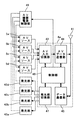
本発明の第1の実施形態について、図面を参照して説明する。図1は、本実施形態の無線通信システムの構成を示す外観図である。又、図2は、本実施形態の無線通信システムを構成する各装置の内部構成を示すブロック図である。尚、図1において、図29の無線通信システムと同一の部分については、同一の符号を付して、その詳細な説明は省略する。
【0031】
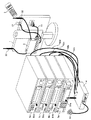
図1の無線通信システムは、ディスプレイ1と、リモコン2と、AVデータ受信装置3と、AVデータ送信装置4と、AVソース機器5a〜5dとから構成される。このとき、AVデータ受信装置3は、図29の無線通信システムにおけるAVデータ受信装置303と同様、受光部31とアンテナ32とを備えるとともに、ケーブル11によってディスプレイ1と接続される。又、AVデータ送信装置4は、アンテナ41と発光部42とを備えるとともに、ケーブル52a〜52dそれぞれによってAVソース機器5a〜5dと接続される。
【0032】
このような無線通信システムにおいて、図2のように、AVデータ受信装置3は、受光部31及びアンテナ32と、アンテナ32で受信した映像信号及び音声信号となるAVデータ信号に基づく無線信号を復調するとともにデータ伸長などして復号化することによってAVデータ信号とするAVデータ受信部33と、受光部31で受信した赤外線信号より指示された制御動作を確認するとともに装置全体を制御する制御部34と、制御部34で確認された制御動作に基づいて符号化するとともに変調することによって制御信号となる無線信号を生成してアンテナ32を介して送信するデータ通信部35とを備える。
【0033】
又、AVデータ送信装置4は、アンテナ41及び発光部42と、AVソース機器5a〜5dより送信されるAVデータ信号を切り換えるAV入力切換部43と、AV入力切換部43から与えられるAVデータ信号をデータ圧縮などして符号化するとともに変調することによって無線信号を生成してアンテナ41を介して送信するAVデータ送信部44と、アンテナ41で受信した制御信号となる無線信号を復調するとともに復号化するデータ通信部45と、データ通信部45で得られた制御信号より制御動作を確認するとともに装置全体を制御する制御部46とを備える。
【0034】
このとき、AVデータ送信装置4は、制御部46で確認した制御信号に基づいて発光部42内の赤外線発光素子を発光させることによって、発光部42より赤外線信号を送信させる。又、発光部42内の赤外線発光素子となるLED42yは、図3のように複数設けられる。即ち、複数のLED42yを略円錐状に配置するとともに、LED42yの発光部が円状で密接した状態となるように配置することによって、発光部の指向性を広くすることができる。よって、図4のように、発光部42から照射される赤外線の照射範囲がBのように広くなり、この照射範囲B内に、AVソース機器5a〜5dそれぞれの受光部51a〜51d全てを存在させることができる。このように構成される無線通信システムにおける各装置の動作について、図面を参照して説明する。
【0035】
(リモコン2の各キーに対する機能の割り当て)
リモコン2によって、ディスプレイ1及びAVデータ送信装置4及びAVソース機器5a〜5dのそれぞれの機能に対して操作することができる。図5に、このリモコン2の各キーに対する機能である操作コードを表す表を示す。図5のように、リモコン2には、TV電源キー、音量UPキー、音量DOWNキー、電源キー、再生キー、一時停止キー、停止キー、早送りキー、巻き戻しキー、録画キー、スロー再生キー、頭出し用キー(次、前)、矢印キー(↑、↓、←、→)、ナンバーキー(1〜12)、入力切換キー、メニューキー(A〜D)を有する。
【0036】
今、AVソース機器5a,5b,5c,5dがそれぞれ、DVD、VTR1、VTR2、チューナであるとすると、ディスプレイ1及びAVソース機器5a〜5dに対する操作コードが、図5に示す表のようになる。図5によると、TV電源キー、音量UPキー、音量DOWNキーが、ディスプレイ1の電源及び音量を操作するための操作コードが割り当てられ、他の装置を操作することができない。
【0037】
逆に、電源キー、再生キー、一時停止キー、停止キー、早送りキー、巻き戻しキー、録画キー、スロー再生キー、頭出し用キー、矢印キー、ナンバーキー、及びメニューキーは、AVソース機器5a〜5dそれぞれに対する操作コードが割り当てられ、ディスプレイ1を操作することができない。又、入力切換キーは、不図示であるが、AVデータ送信装置4に対して、AVデータを取得するAVソース機器5a〜5dを切り換えるための操作コードが割り当てられる。
【0038】
よって、リモコン2のTV電源キーが操作されると、ディスプレイ1の電源がON/OFFし、又、音量UPキー、音量DOWNキーが操作されると、ディスプレイ1の音量が変化する。又、リモコン2の入力切換キーが操作されると、AVデータ送信装置4で選択されるAVデータを出力するAVソース機器が、操作される度に、5a→5b→5c→5d→5aの順に切り替わる。
【0039】
更に、リモコン2の電源キー、再生キー、一時停止キー、停止キー、早送りキー、巻き戻しキー、録画キー、スロー再生キー、頭出し用キー、矢印キー、ナンバーキー、及びメニューキーが操作されると、AVデータ受信装置3より、操作されたキーを示す制御信号を無線信号としてAVデータ送信装置4に送信する。この制御信号となる無線信号を受信したAVデータ送信装置4は、現在、選択しているAVデータを出力するAVソース機器に応じて、操作コードを認識し、それに応じた赤外線信号を生成して送信する。
【0040】
(AVデータ受信装置3の制御信号の処理動作)
まず、AVデータ受信装置3の動作について説明する。AVデータ受信装置3は、図6に示すフローチャートに従って動作を行う。電源が投入されるなどして動作を開始すると、受光部31で赤外線信号を受信したか否かが確認される(STEP1)。このとき、赤外線信号の受信が確認されると(Yes)、制御部34において、受信した赤外線信号がディスプレイ1を操作するための信号であるか否かを確認する(STEP2)。
【0041】
そして、この赤外線信号がディスプレイ1操作用の信号でないとき(No)、制御部34において、受信した赤外線信号より指示された制御信号を確認し、データ通信部35を制御して、この制御信号に基づいて非同期データ通信用の無線信号を生成して、アンテナ32を介して送信する(STEP3)。即ち、リモコン2において、図5のTV電源キー、音量UPキー、音量DOWNキー以外のキーが操作されたとき、受信した赤外線信号より、操作されたキーに対応する制御信号を確認し、この制御信号による無線信号を生成して送信する。
【0042】
STEP1において、赤外線信号の受信が確認されなかったとき(No)、又、STEP2において、受信した赤外線信号がディスプレイ1操作用の信号であったとき(Yes)、又、STEP3における制御信号となる無線信号の送信動作が終了したとき、電源OFFするように操作されたか否かが確認される(STEP4)。このとき、電源OFFするように操作された場合(Yes)、動作を終了し、又、電源OFFの指示がない場合は(No)、再び、STEP1からの動作が行われる。
【0043】
(AVデータ送信装置4の制御信号の処理動作)
1.全体動作
次に、AVデータ送信装置4の動作について説明する。AVデータ送信装置4は、図7に示すフローチャートに従って動作を行う。電源が投入されるなどして動作を開始すると、アンテナ41で制御信号となる無線信号を受信したか否かが確認される(STEP11)。このとき、制御信号となる無線信号がアンテナ41で受信され、データ通信部45で復調された後に復号化されると(Yes)、制御部46において、データ通信部45で復号化されて得られた制御信号より、入力されるAVデータ信号の入力切換が行われるか確認される(STEP12)。
【0044】
そして、リモコン2において、図5のTV電源キー、音量UPキー、音量DOWNキー、入力切換キー以外のキーが操作され、制御信号がAVソース機器の操作を行うためのものであるとき(No)、後述する図8又は図9のフローチャートに示すAV機器操作動作を行う(STEP13)。又、リモコン2において、図5の入力切換キーが操作され、制御信号がAVデータ信号の切り換えを要求する場合は(Yes)、後述する図10のフローチャートに示す入力切換動作を行う(STEP14)。
【0045】
STEP11において、制御信号となる無線信号が受信されなかったとき(No)、又、STEP13のAV機器操作動作又はSTEP14の入力切換動作が終了したとき、電源OFFするように操作されたか否かが確認される(STEP15)。このとき、電源OFFするように操作された場合(Yes)、動作を終了し、又、電源OFFの指示がない場合は(No)、再び、STEP11からの動作が行われる。
【0046】
2.AV機器操作動作の第1例
このとき、STEP13におけるAV機器操作動作が行われる場合、図8に示すフローチャートに従って動作する。まず、制御部46において、AV入力切換部43でAVデータ信号を入力するように設定されたAVソース機器がAVソース機器5a〜5dのいずれであるか確認される(STEP21)。このとき、AVデータ信号を入力するように設定されたAVソース機器は、入力機器番号より確認される。
【0047】
即ち、入力機器番号が5aであるときはAVソース機器5aからのAVデータ信号を、入力機器番号が5bであるときはAVソース機器5bからのAVデータ信号を、入力機器番号が5cであるときはAVソース機器5cからのAVデータ信号を、入力機器番号が5dであるときはAVソース機器5dからのAVデータ信号を、AV入力切換部43で選択しAVデータ送信部44に与える。
【0048】
このように、STEP21で入力機器番号が確認されると、制御部46において、確認された入力機器番号とデータ通信部45で得られた制御信号とから、ユーザーが指示した制御動作に関するデータである操作コードが確認される(STEP22)。即ち、リモコン2において、図5のTV電源キー、音量UPキー、音量DOWNキー、入力切換キー以外のキーが操作されたとき、制御部46において、入力機器番号より操作するAVソース機器を確認するとともに、制御信号より操作されたキーを確認する。そして、制御信号より確認されたリモコン2のキーにおける、入力機器番号より確認されたAVソース機器に対する操作コードを確認する。
【0049】
そして、この操作コードの確認を行った後、その操作コードが有効であるか否かの判定を行う(STEP23)。このとき、有効であれば(Yes)、発光部42を発光させて確認された操作コードに応じた赤外線信号を送信するとともに(STEP24)、現在AVデータ信号を入力しているAVソース機器の動作状態を制御部46内のメモリなどに記録する(STEP25)。STEP23において、制御部46で確認された操作コードが無効であったとき(No)、又は、STEP25におけるAVソース機器の動作状態を記憶すると、AV機器操作動作を終了して、STEP15に移行する。
【0050】
このように、AV機器操作動作する際において、STEP21において入力機器番号を確認するとき、制御部46がAV入力切換部43の状態を確認することによって入力機器番号が確認されるようにしても構わないし、又は、制御部46がAV入力切換部43の選択するAVデータ信号の切り換えを制御するたびに、不図示のメモリなどに入力機器番号を記憶し、記憶した入力機器番号が確認されるようにしても構わない。
【0051】
3.AV機器操作動作の第2例
又、STEP13におけるAV機器操作動作が行われる場合、上述のような図8のフローチャートに応じた動作例以外に、図9のフローチャートに従った動作を行っても構わない。尚、図9において、図8と同一のステップについては、同一の符号を付すものとして、その詳細な説明は省略する。
【0052】
STEP21で入力機器番号を確認した後、STEP22で、ユーザーが指示した操作コードを確認する。そして、STEP23で、この確認した操作コードが有効であるか否かの判定を行う。このとき、有効であれば(Yes)、第1例と同様に、STEP24で赤外線信号を送信した後、STEP25でAVソース機器の動作状態を記録する。
【0053】
逆に、STEP23で、操作コードが無効であると判定された場合(No)、無効であることを示すためのエラー信号を制御部46で生成してデータ通信部45に与え、データ通信部45でこのエラー信号を符号化した後に変調してアンテナ41を介して送信する(STEP26)。このように、STEP25及びSTEP26の各動作が終了すると、AV機器操作動作を終了して、STEP15に移行する。
【0054】
このエラー信号となる無線信号がAVデータ受信装置3のアンテナ32で受信されると、AVデータ受信装置3において、データ通信部35で復調された後、復号化されてエラー信号が得られる。そして、制御部34において、このデータ通信部35で得られたエラー信号が確認されると、不図示の音声出力部などからエラーを示すビープ音を出力するようにしても構わないし、AVデータ受信部33にエラー表示するための映像信号を与えて、ディスプレイ1に送信し、ディスプレイ1の画面上にエラー表示を行うようにしても構わない。
【0055】
4.入力切換動作
又、STEP14における入力切換動作が行われる場合、図10に示すフローチャートに従って動作する。まず、現在、AVデータ信号をAVデータ送信装置4に対して出力しているAVソース機器のAVデータ信号の出力動作を停止させるための連動機能が有効となっているか否かが確認される(STEP31)。この連動機能の有効及び無効は、AVデータ送信装置4において切り換えられ、不図示のメモリに記録されているものとする。
【0056】
このとき、連動機能が有効と設定されている場合(Yes)、後述する図11のフローチャートに示すAV機器停止制御動作を行った後(STEP32)、後述する図12のフローチャートに示す入力切換処理動作を行う(STEP33)。そして、STEP33の入力切換処理動作を行った後、後述する図13のフローチャートに示すAV機器再開制御動作を行う(STEP34)。
【0057】
又、連動機能が無効と設定されている場合(No)、後述する図12のフローチャートに示す入力切換処理動作を行う(STEP35)。このように、STEP34におけるAV機器再開制御動作及びSTEP35における入力切換処理動作が終了すると、入力切換動作を終了して、STEP15に移行する。
【0058】
4−1 AV機器停止制御動作
STEP32に移行したときに成されるAV機器停止制御動作は、図11のフローチャートに従って行われる。まず、制御部46において、入力機器番号が確認される(STEP101)。そして、この入力機器番号より確認されたAVソース機器の動作状態が確認される(STEP102)。この確認される動作状態は、図8又は図9のフローチャートにおけるSTEP25でのAVソース機器の動作状態の記録によって制御部46内のメモリなどに記録されたものを読み出すことによって確認される。
【0059】
その後、入力機器番号より確認されたAVソース機器の電源をOFF制御する連動機能である自動電源OFF機能を有効としているか否かを確認する(STEP103)。このとき、自動電源OFF機能を有効としている場合(Yes)、STEP102で確認された動作状態より電源がONであるか否かが確認される(STEP104)。
【0060】
今、電源がONである場合(Yes)、操作データを電源OFFするための操作データとして、図8又は図9に示すフローチャートにおけるSTEP24及びSTEP25と同様の動作を行う(STEP105)。即ち、STEP101で確認された入力機器番号に応じたAVソース機器が電源OFFとなるように赤外線信号を発光部42より送信するとともに、制御部46内のメモリなどに動作状態が電源OFFとなったことを記録する。
【0061】
又、STEP103で自動電源OFF機能が無効である場合(No)、AVソース機器の再生動作の停止を制御する連動機能である自動停止機能を有効としているか否かを確認する(STEP106)。このとき、自動停止機能を有効としている場合(Yes)、STEP102で確認された動作状態より再生動作中であるか否かが確認される(STEP107)。尚、再生動作には、早送り再生や巻き戻し再生なども含まれる。
【0062】
今、再生動作を行っている場合(Yes)、操作データを再生動作を停止するための操作データとして、図8又は図9に示すフローチャートにおけるSTEP24及びSTEP25と同様の動作を行う(STEP108)。即ち、STEP101で確認された入力機器番号に応じたAVソース機器が再生動作を停止するように赤外線信号を発光部42より送信するとともに、制御部46内のメモリなどに動作状態が停止状態となったことを記録する。
【0063】
又、STEP106で自動停止機能が無効である場合(No)、AVソース機器の一時停止動作の開始を制御する連動機能である自動一時停止機能を有効としているか否かを確認する(STEP109)。このとき、自動一時停止機能を有効としている場合(Yes)、STEP102で確認された動作状態より再生動作中であるか否かが確認される(STEP110)。
【0064】
今、再生動作を行っている場合(Yes)、操作データを一時停止するための操作データとして、図8又は図9に示すフローチャートにおけるSTEP24及びSTEP25と同様の動作を行う(STEP111)。即ち、STEP101で確認された入力機器番号に応じたAVソース機器が一時停止するように赤外線信号を発光部42より送信するとともに、制御部46内のメモリなどに動作状態が一時停止状態となったことを記録する。
【0065】
STEP105,108,111の動作が終了したとき、又は、STEP104で電源がOFFであるとき(No)、又は、STEP107,110で再生動作中でないとき(No)、又は、STEP109で自動一時停止機能が無効であるとき(No)、このAV機器停止制御動作を終了する。
【0066】
4−2 入力切換処理動作
STEP33又はSTEP35に移行したときに成される入力切換処理動作は、図12のフローチャートに従って行われる。まず、制御部46において、記録された入力機器番号より、現在、AV入力切換部43が選択しているAVデータ信号がAVソース機器5cから送信された信号であるか否かが確認される(STEP151)。このとき、入力機器番号が5cであり、AVソース機器5cからのAVデータ信号を選択していることが確認されると(Yes)、AV入力切換部43で選択するAVデータ信号をAVソース機器5dからの信号に切り換えるとともに、入力機器番号を5dとして記録する(STEP152)。
【0067】
又、STEP151において、入力機器番号が5cでないとき(No)、AV入力切換部43が選択しているAVデータ信号がAVソース機器5bから送信された信号であるか否かが確認される(STEP153)。このとき、入力機器番号が5bであることが確認されると(Yes)、AV入力切換部43で選択するAVデータ信号をAVソース機器5cからの信号に切り換えるとともに、入力機器番号を5cとして記録する(STEP154)。
【0068】
又、STEP153において、入力機器番号が5bでないとき(No)、AV入力切換部43が選択しているAVデータ信号がAVソース機器5aから送信された信号であるか否かが確認される(STEP155)。このとき、入力機器番号が5aであることが確認されると(Yes)、AV入力切換部43で選択するAVデータ信号をAVソース機器5bからの信号に切り換えるとともに、入力機器番号を5bとして記録する(STEP156)。
【0069】
又、STEP153において、入力機器番号が5aでないとき(No)、AV入力切換部43で選択するAVデータ信号をAVソース機器5aからの信号に切り換えるとともに、入力機器番号を5aとして記録する(STEP157)。即ち、STEP151,153,155全てにおいてNoとなるため、入力機器番号が5dであることが確認されることとなり、入力機器番号を5aに切り換える。そして、STEP152,154,156,157の切り換え動作を終了すると、入力切換処理動作を終了する。
【0070】
このように入力切換処理動作が行われるため、AVデータ信号の入力を切り換えるように指示されると、AV入力切換部43によって選択されるAVデータ信号を出力するAVソース機器が、5a→5b→5c→5d→5a…のように、巡回的に切り換えられる。
【0071】
尚、本実施形態では、AVソース機器5a〜5dのように4台の場合について述べたが、AVソース機器がn台の場合も同様に、入力機器番号の確認されるステップがn−1とされる。そして、入力機器番号が一致した場合、そのステップで確認された入力機器番号の次の入力機器番号に設定することで、AV入力切換部43によって選択されるAVデータ信号を出力するAVソース機器が、巡回的に切り換えられる。
【0072】
4−3 AV機器再開制御動作
STEP34に移行したときに成されるAV機器再開制御動作は、図13のフローチャートに従って行われる。AV機器停止制御動作のSTEP101,102における動作と同様、まず、制御部46において、入力機器番号が確認された後(STEP201)、この入力機器番号より確認されたAVソース機器の動作状態が確認される(STEP202)。よって、STEP201において、STEP33で切り換えられた入力機器番号が確認される。
【0073】
その後、STEP202で確認された動作状態よりAVソース機器が一時停止中であるか否かが確認される(STEP203)。このとき、一時停止中であることが確認されると(Yes)、AVソース機器の一時停止動作の解除を制御する連動機能である自動一時停止解除機能を有効としているか否かを確認する(STEP204)。
【0074】
今、自動一時停止解除機能を有効としている場合(Yes)、操作データを一時停止を解除するための操作データとして、図8又は図9に示すフローチャートにおけるSTEP24及びSTEP25と同様の動作を行う(STEP205)。即ち、STEP201で確認された入力機器番号に応じたAVソース機器が一時停止を解除して再生動作を行うように赤外線信号を発光部42より送信するとともに、制御部46内のメモリなどに動作状態が再生状態となったことを記録する。
【0075】
又、STEP203で一時停止状態でない場合(No)、STEP202で確認された動作状態よりAVソース機器が停止中であるか否かが確認される(STEP206)。このとき、停止中であることが確認されると(Yes)、AVソース機器の再生動作の停止を制御する連動機能である自動再生機能を有効としているか否かを確認する(STEP207)。
【0076】
今、自動再生機能を有効としている場合(Yes)、操作データを再生動作を行うための操作データとして、図8又は図9に示すフローチャートにおけるSTEP24及びSTEP25と同様の動作を行う(STEP208)。即ち、STEP201で確認された入力機器番号に応じたAVソース機器が再生動作を行うように赤外線信号を発光部42より送信するとともに、制御部46内のメモリなどに動作状態が再生状態となったことを記録する。
【0077】
又、STEP206で停止状態でない場合(No)、STEP202で確認された動作状態よりAVソース機器が電源OFFであるか否かが確認される(STEP209)。このとき、電源OFFであることが確認されると(Yes)、AVソース機器の電源をON制御する連動機能である自動電源ON機能を有効としているか否かを確認する(STEP210)。
【0078】
今、自動電源ON機能を有効としている場合(Yes)、操作データを電源ONするための操作データとして、図8又は図9に示すフローチャートにおけるSTEP24及びSTEP25と同様の動作を行う(STEP211)。即ち、STEP201で確認された入力機器番号に応じたAVソース機器が電源ONとなるように赤外線信号を発光部42より送信するとともに、制御部46内のメモリなどに動作状態が電源ONとなったことを記録する。このとき、電源ONとするだけでなく、再生動作も開始するようにしても構わない。
【0079】
STEP205,208,211の動作が終了したとき、又は、STEP204で自動一時解除機能が無効であるとき(No)、又は、STEP207で自動再生機能が無効であるとき(No)、又は、STEP210で自動電源ON機能が無効であるとき(No)、又は、STEP209で動作状態が電源OFFでないとき(No)、このAV機器再開制御動作を終了する。
【0080】
上述のように、自動電源ON/OFF機能の有効及び無効の設定を行うことができるので、例えば、電源をONした後、立ち上がりの早いAVソース機器については、この自動電源ON/OFF機能を有効として電力消費を抑制することができる。又、電源をONした後、立ち上がりの遅いAVソース機器については、この自動電源ON/OFF機能を無効として再生動作を再開したときの待ち時間を短くすることができる。
【0081】
又、このように立ち上がりの遅いAVソース機器については、自動一時停止/一時停止解除機能又は自動停止・再開機能を用いて、入力選択が解除されたとき、AVソース機器を停止状態又は一時停止状態にして、例えば、DVDなどにおけるモータなどの駆動を停止させることで、電力消費を抑制することができる。更に、自動電源OFF機能、自動一時停止機能、又は自動停止機能を無効とすることによって、例えば、録画中のビデオなど、その動作を停止すると困るAVソース機器について、入力切換後もその動作を継続させることができる。
【0082】
このように、AVデータ送信装置4が動作するとき、複数のAVソース機器からのAVデータの入力切換を行ったときや、AVソース機器の操作を行ったときなどにおいて、入力切換されたAVデータを送信するAVソース機器を示すデータ信号、又は、AVソース機器の動作状態を示すデータ信号などを、データ通信部45で生成して送信するようにしても構わない。このようなデータ信号をAVデータ受信装置3が受信すると、データ通信部35でそのデータ信号が解析され、入力切換されたAVデータを送信するAVソース機器又はAVソース機器の動作状態を確認すると、確認されたAVソース機器又はAVソース機器の動作状態をディスプレイ1に与えて、表示させることができる。
【0083】
(AVデータ信号の送受信)
AVソース機器5a〜5dから、AVデータ信号がケーブル52a〜52dを介してAVデータ送信装置4に送信される。AVデータ送信装置2において、このAVソース機器5a〜5dからのAVデータ信号より、AV入力切換部43で制御部46によって設定された入力機器番号に従って、1つのAVデータ信号を選択してAVデータ送信部44に与える。
【0084】
AVデータ信号送信部44では、AVデータ信号をデータ圧縮して符号化した後、所定の搬送波周波数を用いて変調し、無線信号としてアンテナ41より送信する。このAVデータ送信装置4から送信されたAVデータ信号の無線信号が、AVデータ受信装置3のアンテナ32で受信されると、AVデータ受信部33でミキシングなどが施されて復調した後、AVデータ信号をデータ伸長して復号化する。そして、AVデータ受信部33で得られたAVデータ信号が、ケーブル11を介してディスプレイ1に与えられ、ディスプレイ1において映像及び音声が再生される。
【0085】
<第2の実施形態>
本発明の第2の実施形態について、図面を参照して説明する。尚、本実施形態では、第1の実施形態と同様、図1及び図2に示されるような構成の無線通信システムとなる。よって、本実施形態における無線通信システムの構成の説明は省略する。
【0086】
本実施形態において、AVデータ受信装置3の制御信号の処理動作が、第1の実施形態と同様、図6に示すフローチャートに従った動作となる。又、AVデータ送信装置4の制御信号の処理動作においても、第1の実施形態と同様、その全体動作が図7に示すフローチャートに従った動作に、又、AV機器操作動作が図8又は図9のフローチャートに従った動作になる。更に、AVデータ信号の送受信についても、第1の実施形態と同様の動作を各装置が行うことによって成される。
【0087】
そして、本実施形態では、AVデータ送信装置4の制御信号の処理動作における入力切換動作が、第1の実施形態と異なる動作となる。尚、この入力切換動作において、第1の実施形態と異なる点は、STEP35における入力切換処理を行う際の動作フローのみである。よって、入力切換動作自体の動作については、第1の実施形態と同様、図10に示すフローチャートに従った動作である。
【0088】
以下に、本実施形態における入力切換動作について、図面を参照して説明する。図7のフローチャートにおけるSTEP14の入力切換動作が行われるとき、図10のフローチャートに示すように、まず、連動機能が有効であるか否かが確認される(STEP31)。
【0089】
この連動機能が有効であるときは(Yes)、第1の実施形態で説明したように、図11のフローチャートに従ったAV機器停止制御動作を行った後(STEP32)、図12のフローチャートに示す入力切換処理動作を行う(STEP33)。そして、図13のフローチャートに示すAV機器再開制御動作を行い(STEP34)、入力切換動作を終了して、STEP15に移行する。尚、STEP32〜STEP34の動作については、このような順番に行われなくても良い。例えば、入力切換処理動作を行う前に、AV機器再開制御動作を行うようにしても構わない。
【0090】
又、STEP31において、連動機能が無効であるときは(No)、以下に示す図14のフローチャートに従った入力切換処理動作を行い(STEP35)、入力切換動作を終了して、STEP15に移行する。このときの入力切換処理動作について、図14のフローチャートを参照して説明する。
【0091】
(入力切換処理動作)
第1の実施形態と同様、まず、入力機器番号が5cであるか確認される(STEP151)。このとき、入力機器番号が5cであると(Yes)、制御部46において、AVソース機器5cを電源OFFするための制御信号を送信することを示すフラグをセットする(STEP160)。そして、AVソース機器5cを電源OFFするための制御信号を所定時間後に送信するためのタイマをセットする(STEP161)。その後、第1の実施形態と同様、AV入力切換部43で選択するAVデータ信号をAVソース機器5dからの信号に切り換えるとともに、入力機器番号を5dとして記録する(STEP152)。
【0092】
又、STEP151において、入力機器番号が5cでないとき(No)、第1の実施形態と同様、入力機器番号が5bであるか確認される(STEP153)。このとき、入力機器番号が5bであると(Yes)、制御部46において、AVソース機器5bを電源OFFするための制御信号を送信するためのフラグ及びタイマをセットする(STEP162,163)。そして、第1の実施形態と同様、AV入力切換部43で選択するAVデータ信号をAVソース機器5cからの信号に切り換えるとともに、入力機器番号を5cとして記録する(STEP154)。
【0093】
又、STEP153において、入力機器番号が5bでないとき(No)、第1の実施形態と同様、入力機器番号が5aであるか確認される(STEP155)。このとき、入力機器番号が5aであると(Yes)、制御部46において、AVソース機器5aを電源OFFするための制御信号を送信するためのフラグ及びタイマをセットする(STEP164,165)。そして、第1の実施形態と同様、AV入力切換部43で選択するAVデータ信号をAVソース機器5bからの信号に切り換えるとともに、入力機器番号を5bとして記録する(STEP156)。
【0094】
又、STEP155において、入力機器番号が5aでないとき(No)、制御部46において、AVソース機器5dを電源OFFするための制御信号を送信するためのフラグ及びタイマをセットする(STEP166,167)。そして、第1の実施形態と同様、AV入力切換部43で選択するAVデータ信号をAVソース機器5aからの信号に切り換えるとともに、入力機器番号を5aとして記録する(STEP157)。そして、STEP152,154,156,157の切り換え動作を終了すると、入力切換処理動作を終了する。
【0095】
このように入力切換処理動作が行われるため、AVデータ信号の入力を切り換えるように指示されると、第1の実施形態と同様、AV入力切換部43によって選択されるAVデータ信号を出力するAVソース機器が、5a→5b→5c→5d→5a…のように、巡回的に切り換えられる。又、このとき、電源をOFFするための制御信号を送信するためのフラグ及びタイマが、5b→5c→5d→5a→5b…のように、巡回的にセットされる。
【0096】
このように、本実施形態において、連動機能が無効である場合、入力切換処理動作を行う際に、切り換え前のAVソース機器を所定時間経過後に自動的に電源OFFするように、フラグ及びタイマをセットする。よって、このようにフラグ及びタイマをセットしたときに、自動的に電源OFFするための制御信号となる無線信号をAVソース機器に送信するためのタイマ動作を行う。このときのタイマ動作を以下に説明する。
【0097】
(自動電源OFF制御のタイマ動作の第1例)
このとき、以下において説明を簡単にするために、入力機器番号5a〜5dをそれぞれ、入力機器番号1〜4とする。又、このタイマ動作の第1例は、図15に示すフローチャートに従った動作となる。
【0098】
まず、制御部46で比較するための機器番号をNとしたとき、この機器番号Nを初期値である「1」に設定する(STEP251)。そして、AV入力切換部43に与えられる機器番号K(Kは1〜4)が制御部46で確認される(STEP252)。STEP252で確認された機器番号Kが、STEP251又は後述するSTEP258で設定された機器番号Nと比較される(STEP253)。即ち、AV入力切換部43で選択されるAVデータ信号を出力するAVソース機器が、機器番号NのAVソース機器に相当するか否かが確認される。
【0099】
このとき、機器番号Kが機器番号Nと異なるとき(No)、機器番号NとなるAVソース機器に対するフラグがセットされているか否かが確認される(STEP254)。そして、フラグがセットされているとき(Yes)、制御部46でセットされたタイマによる時間が確認され、所定時間が経過したか否かが確認される(STEP255)。
【0100】
このとき、所定時間が経過したことが確認されると(Yes)、機器番号Nに対するフラグがリセットされる(STEP256)。そして、機器番号NとなるAVソース機器に対して電源OFFとするための制御信号が制御部46で生成された後、発光部52より赤外線信号が送信される(STEP257)。よって、この赤外線信号を受信した機器番号NのAVソース機器の電源がOFFとなる。
【0101】
STEP253で機器番号Kが機器番号Nと一致するとき(Yes)、又は、STEP254でフラグがセットされていないとき(No)、又は、STEP255で所定時間の経過が確認されないとき(No)、又は、STEP257での電源OFFするための制御信号の送信動作を行ったとき、機器番号Nを1つ加算して設定する(STEP258)。そして、新たに設定した機器番号Nが、4より大きいか否かが確認される(STEP259)。
【0102】
STEP259で機器番号Nが4を超えなかったとき(No)、新たに設定した機器番号Nに対して、STEP253〜STEP258の動作を行う。又、機器番号Nが4を超えるとき(Yes)、再び、機器番号Nを初期値である「1」に設定する(STEP260)。そして、STEP253と同様、STEP252で確認された機器番号KとSTEP260又は後述するSTEP263で設定された機器番号Nとが一致するか比較する(STEP261)。
【0103】
このとき、機器番号Kが機器番号Nと異なるとき(No)、機器番号NのAVソース機器に対するフラグがセットされているか否かが確認される(STEP262)。そして、フラグがセットされているとき(Yes)、STEP255に移行して、所定時間が経過したか否かが確認された後、このSTEP255以降の動作を行う。
【0104】
STEP261で機器番号Kが機器番号Nと一致するとき(Yes)、又は、STEP262でフラグがセットされていないとき(No)、機器番号Nを1つ加算して設定する(STEP263)。そして、新たに設定した機器番号Nが、4より大きいか否かが確認される(STEP264)。STEP263で機器番号Nが4を超えなかったとき(No)、新たに設定した機器番号Nに対して、STEP261以降の動作を行う。又、機器番号Nが4を超えるとき(Yes)、このタイマ動作を終了する。
【0105】
このようにすることで、例えば、機器番号2のAVソース機器5bのAVデータ信号がAV入力切換部43で選択されているとき、まず、機器番号1のAVソース機器5aに対するフラグのセットが成されているか確認した後、セットされているときは、そのタイマより所定時間経過しているか否かを確認する。そして、次に、機器番号3のAVソース機器5cに対するフラグのセットが成されているか確認した後、セットされているときは、そのタイマより所定時間経過しているか否かを確認する。
【0106】
最後に、機器番号4のAVソース機器5dに対するフラグのセットが成されているか確認した後、セットされているときは、そのタイマより所定時間経過しているか否かを確認する。このようにして動作している間に、タイマが所定時間経過しているAVソース機器に対しては、そのフラグをリセットするとともに、電源OFFするための制御信号となる赤外線信号を送信する。
【0107】
その後、AV入力切換部43で選択されているAVデータ信号を出力するAVソース機器5b以外のAVソース機器5a,5c,5dのフラグが全てリセットされているか否かが確認され、全てリセットされていると、タイマ動作を終了する。
【0108】
(自動電源OFF制御のタイマ動作の第2例)
AVソース機器を所定時間経過後に自動的にOFFさせるために、自動電源OFF機能を有している場合、この自動電源OFF機能を有効又は無効として設定することができる。よって、このとき、上述の第1例における図15のフローチャートに、自動電源OFF機能が有効であるか否かを確認するステップを設ける必要がある。このような自動電源OFF機能が有効であるかの確認を行うためのステップを追加した例を、図16のフローチャートに示す。
【0109】
図16のフローチャートにおいて、図15のフローチャートと同一の動作ステップについては同一の符号を付して、その詳細な説明は省略する。本例では、上述の第1例と異なり、STEP253で機器番号Kと機器番号Nとを比較して一致しなかったとき(No)、機器番号NのAVソース機器に対する自動電源OFF機能を有効としているか否かが確認される(STEP271)。このとき、自動電源OFF機能を有効としている場合は(Yes)、フラグがセットされているか否かの確認が行われ(STEP254)、逆に、自動電源OFF機能を無効としている場合は(No)、機器番号Nを1つ加算して設定する(STEP258)。
【0110】
又、同様に、STEP261で機器番号Kと機器番号Nとを比較して一致しなかったとき(No)、第1例と異なり、機器番号NのAVソース機器に対する自動電源OFF機能を有効としているか否かが確認される(STEP272)。このとき、自動電源OFF機能を有効としている場合は(Yes)、フラグがセットされているか否かの確認が行われ(STEP262)、逆に、自動電源OFF機能を無効としている場合は(No)、機器番号Nを1つ加算して設定する(STEP263)。
【0111】
このように、本実施形態においては、図10のフローチャートにおけるSTEP35での入力切換処理動作が行われた場合でも、所定時間が経過すると、AV入力切換部43でAVデータ信号が選択されていないAVソース機器に対して、AVデータ送信装置2より赤外線信号を送信して、自動的に電源OFFするように制御することができる。
【0112】
尚、本実施形態において、タイマによる所定時間は、ユーザーによって設定可能であるものとしても構わない。このようにすることで、例えば、ゆっくり視聴するAVソース機器を決定している場合は、タイマによる所定時間を長く設定することができ、又、できる限り電力消費を抑制したい場合は、タイマによる所定時間を短く設定することができるなど、ユーザーの所望する時間に設定することができる。
【0113】
第1及び第2の実施形態のように、AVデータ送信装置4に設けられた発光部42を、図3のように複数のLEDを備えることによって、発光部42から照射される赤外線の照射範囲を広くして、広い指向性を持つものとしても構わない。しかしながら、AVソース機器に同一メーカの同一機器を複数台用いた場合、その制御コードが1組又は2組しかないため、このような同一機器をAVデータ送信装置4によって個別に制御することができない場合がある。よって、このような場合でも個別に制御できるような実施形態を以下に示す。
【0114】
<第3の実施形態>
本発明の第3の実施形態について、図面を参照して説明する。図17は、本実施形態の無線通信システムの構成を示す外観図である。又、図18は、本実施形態の無線通信システムを構成する各装置の内部構成を示すブロック図である。尚、図17及び図18において、図1及び図2の無線通信システムと同一の部分については、同一の符号を付して、その詳細な説明は省略する。
【0115】
図17の無線通信システムは、第1又は第2の実施形態と同様、ディスプレイ1と、リモコン2と、AVデータ受信装置3aと、AVデータ送信装置4aと、AVソース機器5a〜5dとから構成される。このとき、AVデータ受信装置3aは、図1におけるAVデータ受信装置3と異なり、赤外線信号を受信する受光部31が備えられず、ディスプレイ1で受信された制御信号を電気信号としてディスプレイ1から与えられる。又、AVデータ送信装置4aは、図1におけるAVデータ送信装置4と異なり、AVソース機器5a〜5dのそれぞれに設けられた受光部51a〜51dのそれぞれに赤外線信号を送信するための発光部42a〜42dを備える。
【0116】
又、このような無線通信システムにおいて、図18のように、ディスプレイ1の受光部12において赤外線信号が受信され、この受信された赤外線信号がAVデータ受信装置3aの制御部34に与えられる。又、AVデータ送信装置4aは、発光部42a〜42dより赤外線信号を送信するためのものを選択する発光部切換部47を有し、この発光部切換部47は制御部46によって制御される。尚、図18において、その他の構成については、図2の構成と同様である。又、発光部42a〜42dは、図19のようになる。即ち、取り付け部112の上に赤外線発光素子111が設置されるとともに発光部切換部47から制御信号を与えるための信号線113が設けられた発光ユニットとして構成される。
【0117】
このように、無線通信システムが構成されるとき、各装置の動作は、AVデータ送信装置4aがAVソース機器5a〜5dを操作するための赤外線信号の送信動作と、リモコン2から赤外線信号の受信動作以外は、第2の実施形態の無線通信システムと同一の動作を行うものとする。よって、赤外線信号受信動作、AV機器操作動作、AV機器停止制御動作、AV機器再開制御動作、及び、自動電源OFF制御のタイマ動作における異なる点を説明するとともに、他の同一の動作についての説明は省略する。
【0118】
まず、赤外線信号の受信動作について、説明する。リモコン2から赤外線信号が送信されると、ディスプレイ1の受光部12で赤外線信号が受信される。そして、ディスプレイ1において、受信された赤外線信号が、TV電源キー、音量UPキー、音量DOWNキーなどが操作され、ディスプレイ1を制御するための信号であるか否かが確認される。このとき、ディスプレイ1を制御するための信号である場合、その信号に従って、ディスプレイの電源のON/OFF又は音量の変更が行われる。
【0119】
又、ディスプレイ1で受信した赤外線信号が、ディスプレイ1を制御するための信号でない場合、この制御信号を電気信号に変換して、AVデータ受信装置3aに出力する。AVデータ受信装置3aでは、ディスプレイ1より与えられた電気信号より制御信号を制御部34で確認し、データ通信部35を制御して、この制御信号に基づいた無線信号を生成して、アンテナ32を介して送信する。
【0120】
次に、AVデータ送信装置4aのAV機器操作動作について、図20のフローチャートに従って説明する。尚、図20のフローチャートにおいて、図9に示すフローチャートに従って動作する。又、本実施形態では、第1の実施形態におけるAV機器操作動作の第2例と同様の動作をするものとするが、第1例と同様の動作をするものとしても構わない。
【0121】
第1の実施形態における第2例と同様、STEP21で入力機器番号を確認した後、STEP22で、ユーザーが指示した操作コードを確認する。そして、STEP23で、この確認した操作コードが有効であるか否かの判定を行う。このとき、有効であれば(Yes)、発光部切換部47によって、STEP21で確認された入力機器番号に応じたAVソース機器に対して赤外線信号を送信する発光部を発光部42a〜42dより選択する(STEP27)。
【0122】
そして、制御部46で確認された制御信号が発光部切換部47を介して、選択された発光部に与えられ、発光部より赤外線信号が送信される(STEP24)。よって、選択された発光部の赤外線発光素子111から赤外線信号が、AVソース機器の受信部で受信される。このとき、AVソース機器の動作状態を制御部46内のメモリなどに記録する(STEP25)。
【0123】
又、STEP23で、操作コードが無効であると判定された場合(No)、無効であることを示すためのエラー信号をアンテナ41を介して送信する(STEP26)。このように、STEP25及びSTEP26の各動作が終了すると、AV機器操作動作を終了する。
【0124】
又、AV機器停止制御動作は、図11のフローチャートに従って行われるが、STEP105、STEP108、STEP111の動作において、図20のフローチャートに示すSTEP27、STEP24及びSTEP25と同様の動作を行う。即ち、STEP105では、まず、STEP101で得られた入力機器番号に応じた発光部を発光部切換部47で選択する。そして、AVソース機器が電源OFFとなるように赤外線信号を発光部切換部47で選択した発光部より送信するとともに、制御部46内のメモリなどに動作状態が電源OFFとなったことを記録する。
【0125】
同様に、STEP108においても、入力機器番号に応じた発光部を発光部切換部47で選択した後、AVソース機器が再生動作を停止するように赤外線信号を発光部切換部47で選択した発光部より送信するとともに、制御部46内のメモリなどに動作状態が停止状態となったことを記録する。又、STEP111においても、入力機器番号に応じた発光部を発光部切換部47で選択した後、AVソース機器が一時停止するように赤外線信号を発光部切換部47で選択した発光部より送信するとともに、制御部46内のメモリなどに動作状態が一時停止状態となったことを記録する。
【0126】
又、AV機器再開制御動作についても、図13のフローチャートに従って行われるが、STEP205、STEP208、STEP211の動作において、AV機器停止制御動作と同様、図20のフローチャートに示すSTEP27、STEP24及びSTEP25と同様の動作を行う。即ち、STEP201で得られた入力機器番号に応じた発光部を発光部切換部47で選択し、赤外線信号を発光部切換部47で選択した発光部より送信するとともに、制御部46内のメモリなどに動作状態を記録する。
【0127】
更に、自動電源OFF制御のタイマ動作についても、図16のフローチャートに従って行われるが、STEP257の動作において、AV機器停止制御動作と同様、図20のフローチャートに示すSTEP27、STEP24及びSTEP25と同様の動作を行う。即ち、設定された入力機器番号に応じた発光部を発光部切換部47で選択し、赤外線信号を発光部切換部47で選択した発光部より送信するとともに、制御部46内のメモリなどに動作状態を記録する。尚、本実施形態では、第2の実施形態における自動電源OFF制御のタイマ動作の第2例と同様の動作をするものとしたが、第1例と同様の動作をするものとしても構わない。
【0128】
尚、本実施形態において、AVデータ送信装置4aが第2の実施形態の動作を基本とした動作を行うものとしたが、自動電源OFF制御のタイマ動作を行わない第1の実施形態の動作を基本とした動作を行うものとしても構わない。
【0129】
このように、複数のAVソース機器それぞれにの受光部に対して赤外線信号を直接送信する発光部となる発光ユニットが設けられるので、第1及び第2の実施形態と異なり、制御するように選択されたAVソース機器のみに赤外線信号を送信することができる。しかしながら、発光部に備えられた赤外線発光素子の照射範囲は広がりを有する。
【0130】
そのため、図21のように、例えば、発光部42aに設けられた赤外線発光素子111の照射範囲内に、この発光部42aが制御するAVソース機器5aの受光部51a以外に、AVソース機器5bの受光部51bが存在してしまうことがある。よって、AVソース機器5a,5bが同一の機器である場合、誤作動させてしまう恐れがある。よって、同一の機器における誤作動を防ぐことができるような実施形態を以下に示す。
【0131】
<第4の実施形態>
本発明の第4の実施形態について、図面を参照して説明する。図22は、本実施形態の無線通信システムの構成を示す外観図である。又、本実施形態の無線通信システムを構成する各装置の内部構成は、第3の実施形態と同様、図18のようになる。尚、図22において、図17の無線通信システムと同一の部分については、同一の符号を付して、その詳細な説明は省略する。
【0132】
図22の無線通信システムは、第3の実施形態と同様、ディスプレイ1と、リモコン2と、AVデータ受信装置3aと、AVデータ送信装置4bと、AVソース機器5a〜5dとから構成される。このとき、AVデータ送信装置4bは、図17におけるAVデータ送信装置4aと異なり、AVソース機器5a〜5dのそれぞれに設けられた受光部51a〜51dのそれぞれに赤外線信号を送信するための発光部42a〜42dの代わりに、発光部42k〜42nを備える。尚、図18において、発光部42a〜42dが発光部42k〜42nに相当し、AVデータ送信装置4aがAVデータ送信装置4bに相当する。
【0133】
本実施形態では、発光部42k〜42nは、図23のようになる。図23に示すように、図19に示す取り付け部112の上に赤外線発光素子111が設置されるとともに発光部切換部47から制御信号を与えるための信号線113が設けられた発光ユニットに、更に、赤外線発光素子111からの赤外線の照射方向を絞るための遮蔽部114が設けられる。即ち、発光部42k〜42nはそれぞれ、AVソース機器5a〜5dに備えられた受光部51a〜51dに対面する方向以外の照射を防ぐために、受光部51a〜51dに対面する方向以外の方向を覆うように、遮蔽部114が設けられる。
【0134】
即ち、図22のように、発光部42kにおいて、この発光部42kが制御するAVソース機器5a以外のAVソース機器5b,5c,5dに対して赤外線信号が照射されることが遮蔽部114によって防がれる。又、同様に、発光部42lにおいてはAVソース機器5a,5c,5dに対して、発光部42mにおいてはAVソース機器5a,5b,5dに対して、発光部42nにおいてはAVソース機器5a,5b,5cに対して、赤外線信号が照射されることが遮蔽部114によって防がれる。
【0135】
このように、発光部42k〜42nそれぞれが、AVソース機器5a〜5dそれぞれに備えられた受光部51a〜51dにのみ赤外線信号を照射するため、第3の実施形態のように、同一の機器における誤作動を防ぐことができる。尚、本実施形態の無線通信システムにおける各装置の動作については、第3の実施形態と同様であるため、その詳細な説明は省略する。
【0136】
<第5の実施形態>
本発明の第5の実施形態について、図面を参照して説明する。図24は、本実施形態の無線通信システムの構成を示す外観図である。又、本実施形態の無線通信システムを構成する各装置の内部構成は、第4の実施形態と同様、図18のようになる。尚、図24において、図22の無線通信システムと同一の部分については、同一の符号を付して、その詳細な説明は省略する。
【0137】
図24の無線通信システムは、第4の実施形態と同様、ディスプレイ1と、リモコン2と、AVデータ受信装置3aと、AVデータ送信装置4cと、AVソース機器5a〜5dとから構成される。このとき、AVデータ送信装置4cは、図22におけるAVデータ送信装置4bと異なり、AVソース機器5a〜5dのそれぞれに設けられた受光部51a〜51dのそれぞれに赤外線信号を送信するための発光部42k〜42nの代わりに、発光部42p〜42sを備える。尚、図18において、発光部42a〜42dが発光部42p〜42sに相当し、AVデータ送信装置4aがAVデータ送信装置4cに相当する。
【0138】
本実施形態では、発光部42p〜42sは、図25のようになる。即ち、取り付け部112の上に赤外線の照射方向を絞るための遮蔽部114aで覆われた赤外線発光素子111が設置されるとともに発光部切換部47から制御信号を与えるための信号線113が設けられた発光ユニットが構成される。このとき、図23に示す発光ユニットと同様、遮蔽部114aによって、発光部42p〜42sはそれぞれ、AVソース機器5a〜5dに備えられた受光部51a〜51dに対面する方向以外の照射が防がれる。
【0139】
更に、この遮蔽部114aには、リモコン2から送信される赤外線信号を透過させるための赤外線通過部115となる領域が設けられる。この赤外線通過部115は、単に、遮蔽部114aの赤外線を遮蔽する材料を除去することで形成しても構わないし、赤外線を遮蔽する材料を除去した後に、この除去した領域に赤外線を透過させることのできる材料で覆うようにして形成しても構わない。
【0140】
このように構成される遮蔽部114aを備えた発光部がAVソース機器に対して、図26のように設置される。図26では、発光部42sとAVソース機器5dとの設置関係を示すもので、発光部42sを代表して説明する。図26に示すように、遮蔽部114aに設けられた赤外線通過部115がAVソース機器5dの受光部51dと対面する位置となるように、発光部42sが設置される。よって、外部からAVソース機器5dに対応するリモコン2aが操作されて赤外線信号が送信されるとき、この赤外線通過部115を赤外線信号が通過して、受光部51dで受信される。
【0141】
このように、発光部42p〜42sそれぞれが、AVソース機器5a〜5dそれぞれに備えられた受光部51a〜51dにのみ赤外線信号を照射するとともに、外部からの赤外線信号を赤外線通過部115を通過させて受光部51a〜51dに受信させることができる。よって、赤外線通過部115とAVソース機器5a〜5dの受光部51a〜51dとを結ぶ方向から赤外線信号を送信するように、リモコンを操作して、AVソース機器5a〜5dを制御させることができる。尚、本実施形態の無線通信システムにおける各装置の動作については、第3の実施形態と同様であるため、その詳細な説明は省略する。
【0142】
尚、第4の実施形態では、発光部として遮蔽部114を備えた発光ユニットのみを用い、又、第5の実施形態では、発光部として遮蔽部114aを備えた発光ユニットのみを用いたが、遮蔽部114を備えた発光ユニットと遮蔽部114aを備えた発光ユニットとを組み合わせて用いるようにしても構わない。又、遮蔽部114及び遮蔽部114aそれぞれが、一部もしくは全部が取り外しができる構造とし、赤外線信号の入射可能な領域を拡大可能なものとしても構わない。更に、取付部112上の赤外線発光素子111の高さなどの位置調整を行うことができるものとしても構わない。
【0143】
又、第3〜第5の実施形態において、複数の発光部が発光動作を行い、複数のAVソース機器に対して赤外線信号が送信されるようにしても構わない。即ち、例えば、図10のフローチャートにおけるSTEP32のAV機器停止制御動作と、STEP33の入力切換処理動作及びSTEP34のAV機器再開制御動作とが平行して行われ、AV機器停止制御動作によって発光動作をする発光部とAV機器再開制御動作によって発光動作をする発光部とが、ほぼ同時に動作を行うようにしても構わない。
【0144】
<第6の実施形態>
本発明の第6の実施形態について、図面を参照して説明する。図27は、本実施形態の無線通信システムにおけるAVデータ送信装置の内部構成を示すブロック図である。尚、図27において、図18のAVデータ送信装置と同一の部分については、同一の符号を付して、その詳細な説明は省略する。又、AVデータ受信装置の内部構成は、第3の実施形態と同様、図18のようになる。よって、本実施形態においては、AVデータ送信装置について説明するものとして、他の装置についての詳細な説明は省略する。
【0145】
図27に示すAVデータ送信装置4dは、図18のAVデータ送信装置4aと異なり、AVセレクタのようなAV入力切換装置43aが外部に設けられることにより、AV入力切換部43が省かれるとともに、AV入力切換装置43aに対して制御信号となる赤外線信号を送信する発光部48が設けられた構成となる。この発光部48には制御部46より制御信号が与えられる。尚、その他の構成については、図18のAVデータ送信装置4aと同一である。又、AV入力切換装置43aは、不図示だが、赤外線信号を受信するための受光部を備える。
【0146】
このようにAVデータ装置4dが構成されるとき、AVソース機器5a〜5dから出力されるAVデータ信号の内より入力されるAVデータ信号を選択するために、AV入力切換装置43aに対して、選択する入力機器番号を示す制御信号から生成された赤外線信号が発光部48より送信される。よって、AV入力切換装置43aは、発光部48からの赤外線信号を受信すると、この赤外線信号による入力機器番号に従って、AVソース機器5a〜5dから出力されるAVデータ信号の内から選択したAVデータ信号をAVデータ送信装置4dに送信する。
【0147】
このように、本実施形態では、AVソース機器からのAVデータ信号の入力切換を、AVデータ送信装置内で行うのでなく、外部に備えられたAV入力切換装置に赤外線信号を送信して、このAV入力切換装置を制御することで行う。よって、AVセレクタなどのAV入力切換装置が存在するときに流用することができるとともに、AVソース機器からのAVデータ信号の入力切換AVデータ送信装置を小型化することができる。
【0148】
尚、AV入力切換装置に対して赤外線信号を送信するための専用の発光部を設けるようにしたが、第1又は第2の実施形態と同様に、各AVソース機器に対して赤外線信号を送信するための発光部を、AV入力切換装置に対して赤外線信号を送信するためのものとして利用するようにしても構わない。又、AV入力切換装置についても赤外線信号などを用いた無線通信にて制御信号を送信するようにしたが、ケーブルなどで接続して有線通信にて制御信号を送信するようにしても構わない。
【0149】
<第7の実施形態>
本発明の第7の実施形態について、図面を参照して説明する。図28は、本実施形態の無線通信システムをにおけるAVデータ送信装置の内部構成を示すブロック図である。尚、図28において、図18のAVデータ送信装置と同一の部分については、同一の符号を付して、その詳細な説明は省略する。又、AVデータ受信装置の内部構成は、第3の実施形態と同様、図18のようになる。よって、本実施形態においては、AVデータ送信装置について説明するものとして、他の装置についての詳細な説明は省略する。
【0150】
図28に示すAVデータ送信装置4eは、図18のAVデータ送信装置4aにAVソース機器5a〜5dの電源制御を行うための電源制御部49が付加された構成となる。尚、その他の構成については、図18のAVデータ送信装置4aと同一である。このAVデータ装置4eは、AV機器停止制御動作において電源OFFを行う場合、又は、AV機器再開制御動作において電源ONを行う場合、又は、自動電源OFF制御のタイマ動作において電源OFFを行う場合、制御部46によって電源制御部49を制御して、選択したAVソース機器のAC電源をON/OFF制御する。
【0151】
このように、本実施形態では、AC電源を制御することができるので、AVソース機器の電源を完全にOFFとすることが可能である。よって、待機電力を最小限に抑制した無線通信システムを構築することができる。
【0152】
尚、本実施形態において、発光部をAVソース機器それぞれに対して設けたAVデータ装置としたが、第1又は第2の実施形態のように、1つの発光部のみを設け、複数のAVソース機器に赤外線信号を送信することのできるAVデータ送信装置としても構わない。又、本実施形態において、第6の実施形態のように、外部に設けられたAV入力切換装置に対して赤外線信号を送信するようなAVデータ送信装置としても構わない。更に、第6及び第7の実施形態において、発光部4a〜4dの代わりに、第4の実施形態で用いた発光部4k〜4n又は第5の実施形態で用いた発光部4p〜4sとしても構わない。
【0153】
【発明の効果】
本発明によると、広い指向性を有する発光部又は複数の発光部を備えることによって、複数のAVソース機器に対して、赤外線信号を照射することができるため、複数のAVソース機器を安定して制御することができる。又、複数の発光部を備える際、遮蔽部などを設けて、単一のAVソース機器にのみ赤外線信号の照射が可能なものとすることで、動作させたいAVソース機器のみに赤外線信号を送信することができ、他のAVソース機器を誤操作することを防ぐことができる。又、遮蔽部に赤外線通過領域を設けることによって、AVデータ送信装置の発光部以外の外部から、リモートコントローラなどの操作装置を用いて赤外線信号を送信して、AVソース機器の制御を行うことができる。
【0154】
又、入力選択が解除されたAVソース機器の電源をOFFするか、又は、その再生動作を停止させることができるので、入力選択が解除された時点で再生動作を行っているAVソース機器の再生動作を停止される。又、このとき、更に、入力選択が成されたAVソース機器の再生動作を再開できるので、入力選択がなされたとき、入力選択が解除された直後の部分から再生を行うことができる。
【0155】
又、前記AVソース機器の入力選択に連動して、該入力選択が解除された前記AVソース機器の電源を自動的にOFFするための機能、又は、該入力選択が成された前記AVソース機器の自動的にONするための機能について、有効にするか否かの選択ができる。よって、例えば、電源ONにした後、立ち上がりの遅いAVソース機器においてはこの機能を無効とすることができ、再生動作を再開するときの待機時間を短縮することができる。又、この機能を有効としたときは、動作させない待機状態のときに電源OFFとされるため、消費電力を低減することができる。
【図面の簡単な説明】
【図1】本発明の無線通信システムの構成の一例を示す外観図。
【図2】本発明の無線通信システムを構成する各装置の内部構成の一例を示すブロック図。
【図3】発光部の構成を示すための図。
【図4】図1の無線通信システムにおけるAVデータ送信装置の発光部の照射範囲を示す図。
【図5】リモコン機能表の例。
【図6】AVデータ受信装置の制御信号の処理動作を示すフローチャート。
【図7】AVデータ送信装置の制御信号の処理動作を示すフローチャート。
【図8】図1の無線通信システムにおけるAVデータ送信装置のAV機器操作動作の一例を示すフローチャート。
【図9】図1のAVデータ送信装置のAV機器操作動作の一例を示すフローチャート。
【図10】入力切換動作の一例を示すフローチャート。
【図11】AV機器停止制御動作を示すフローチャート。
【図12】入力切換処理動作の一例を示すフローチャート。
【図13】AV機器再開制御動作を示すフローチャート。
【図14】入力切換処理動作の一例を示すフローチャート。
【図15】自動電源OFF制御のタイマ動作の一例を示すフローチャート。
【図16】自動電源OFF制御のタイマ動作の一例を示すフローチャート。
【図17】第3の実施形態の無線通信システムの構成の一例を示す外観図。
【図18】本発明の無線通信システムを構成する各装置の内部構成の一例を示すブロック図。
【図19】図17の無線通信システムにおけるAVデータ送信装置の発光部の構成の一例を示す外観図。
【図20】図17の無線通信システムにおけるAVデータ送信装置のAV機器操作動作の一例を示すフローチャート。
【図21】図17の無線通信システムにおけるAVデータ送信装置の発光部の照射範囲を示す図。
【図22】第4の実施形態の無線通信システムの構成の一例を示す外観図。
【図23】図22の無線通信システムにおけるAVデータ送信装置の発光部の構成の一例を示す外観図。
【図24】第5の実施形態の無線通信システムの構成の一例を示す外観図。
【図25】図24の無線通信システムにおけるAVデータ送信装置の発光部の構成の一例を示す外観図。
【図26】図24の無線通信システムにおけるAVデータ送信装置発光部とAVソース機器との設置関係を示す外観図。
【図27】第6の実施形態の無線通信システムを構成する各装置の内部構成の一例を示すブロック図。
【図28】第7の実施形態の無線通信システムを構成する各装置の内部構成の一例を示すブロック図。
【図29】従来の無線通信システムの構成の一例を示す外観図。
【図30】図29の無線通信システムにおけるAVデータ送信装置の発光部の照射範囲を示す図。
【図31】図29の無線通信システムにおけるAVデータ送信装置の発光部の照射範囲を示す図。
【符号の説明】
1 ディスプレイ
2 リモートコントローラ
3 AVデータ受信装置
4 AVデータ送信装置
5a〜5d AVソース機器
11 ケーブル
31 受光部
32 アンテナ
33 AVデータ受信部
34 制御部
35 データ通信部
41 アンテナ
42 受光部
43 AV入力切換部
44 AVデータ送信部
45 データ通信部
46 制御部
51a〜51d 受光部
52a〜52d ケーブル[0001]
BACKGROUND OF THE INVENTION
The present invention is a wireless communication system that transmits and receives AV data transmitted from an AV source device such as a tuner, video, and DVD to a playback device such as a display, and transmits and receives a control signal for controlling the AV source device. And an AV data transmitting apparatus and AV data receiving apparatus.
[0002]
[Prior art]
In recent years, due to the complexity of wired connections and the development of wireless technologies, AV data is transmitted from AV source devices such as tuners, videos, and DVDs to playback devices such as displays, and video and audio are played back on the playback devices. A wireless communication system for AV data is provided. A transmission / reception apparatus using such a wireless communication system is provided in Japanese Patent Application Laid-Open Nos. 9-74498 and 2000-251456.
[0003]
This conventional wireless communication system has a configuration as shown in FIG. That is, the
[0004]
In addition, the AV
[0005]
In the wireless communication system as shown in FIG. 29, when a user operates the
[0006]
In the AV
[0007]
Further, when the AV source device 5 transmits an AV data signal as a video signal and an audio signal to the AV
[0008]
[Problems to be solved by the invention]
When using the wireless communication system as shown in FIG. 29, the
[0009]
Therefore, in the case of a system for a single AV source device as in the wireless communication system as shown in FIG. 29, an AV data transmission device including a light emitting unit composed of one LED can function sufficiently. it can. However, when an infrared signal serving as a control signal is transmitted from the AV data transmission device to a plurality of AV source devices, since the irradiation range is narrow, only some of the AV source devices receive infrared signals from the AV data transmission device. A signal cannot be received, and all AV source devices cannot be controlled using this wireless communication system.
[0010]
That is, as shown in FIG. 31, when an infrared signal is transmitted from the
[0011]
[Means for Solving the Problems]
In order to achieve the above object, an AV data transmitting apparatus according to the present invention transmits a first communication unit that transmits AV data serving as at least one of a video signal and an audio signal supplied from an AV source device as a first radio signal. A second communication unit that receives a second wireless signal that is a control signal for controlling the AV source device, and a control from the second wireless signal received by the second communication unit to the AV source device In the AV data transmitting apparatus, comprising: a control unit that performs signal confirmation and controls the entire apparatus; and a light emitting unit that generates and transmits an infrared signal based on the control signal confirmed by the control unit. Irradiate infrared signal to each of the AV source devices In addition, when one AV data to be given to the first communication unit is selected from a plurality of AV data given by the plurality of AV source devices, the AV source device whose AV data input selection is canceled is automatically selected. An infrared signal for turning off the power automatically or an infrared signal for automatically stopping the playback operation of the AV source device is transmitted from the light emitting unit. It is characterized by that.
[0012]
In view of such a problem, an object of the present invention is to provide a wireless communication system that can remotely control a plurality of AV source devices that generate AV data from a playback device that plays back an AV data signal. . Another object of the present invention is to provide an AV data transmitting device and an AV data receiving device capable of performing mutual communication between control signals and AV data between a playback device and an AV source device in such a wireless communication system. To do.
[0013]
[Means for Solving the Problems]
In order to achieve the above object, an AV data transmitting apparatus according to the present invention transmits a first communication unit that transmits AV data serving as at least one of a video signal and an audio signal supplied from an AV source device as a first radio signal. A second communication unit that receives a second wireless signal that is a control signal for controlling the AV source device, and a control from the second wireless signal received by the second communication unit to the AV source device In the AV data transmitting apparatus, comprising: a control unit that performs signal confirmation and controls the entire apparatus; and a light emitting unit that generates and transmits an infrared signal based on the control signal confirmed by the control unit. AV source device having a plurality of sections Respectively Infrared signal can be emitted to In addition, when selecting one of a plurality of AV data provided from the plurality of AV source devices as the AV data to be provided to the first communication unit, reproduction of the AV source device from which AV data input selection has been canceled is selected. An infrared signal for automatically stopping the operation is transmitted from the light emitting unit. It is characterized by that.
[0014]
In such an AV data transmitting apparatus, the light emitting unit may be configured by a plurality of infrared light emitting elements so that the directivity is widened. At this time, the directivity of the light emitting part can be widened by arranging the plurality of infrared light emitting elements in a substantially conical shape and arranging the light emitting parts in a circular and intimate state.
[0015]
The AV data transmitting apparatus according to the present invention includes a first communication unit that transmits AV data, which is at least one of a video signal and an audio signal given from an AV source device, as a first wireless signal, and the AV source device. A second communication unit that receives a second wireless signal, which is a control signal for controlling the signal, and confirms a control signal to the AV source device from the second wireless signal received by the second communication unit. In an AV data transmission device comprising: a control unit that controls the entire apparatus; and a light emitting unit that generates and transmits an infrared signal based on a control signal confirmed by the control unit, the light emitting unit includes a plurality of AV A plurality of the light emitting units are provided so that an infrared signal can be emitted to the source device.
[0016]
In such an AV data transmitting apparatus, the plurality of AV source devices are provided with the same number of the light emitting units as the AV source devices to be irradiated so that each of the plurality of AV source devices is irradiated with an infrared signal. Only the AV source device may be able to irradiate infrared rays. At this time, the light emitting units are installed so as to face the light receiving unit that receives the infrared signal of the AV source device.
[0017]
Further, at this time, the light emitting unit emits an infrared signal to the light receiving unit that receives the infrared signal in the AV source device, and infrared rays other than the direction from the infrared light emitting element to the light receiving unit. It may have a shielding part for preventing irradiation. For example, the shielding unit may be provided so as to cover a surface around the infrared light emitting element other than a surface facing a light receiving unit that receives an infrared signal of the AV source device. Furthermore, the shielding part may be removable.
[0018]
Further, an infrared transmissive area through which an infrared signal from the outside can be transmitted is provided in a part of the shielding section, and an infrared signal from the outside can be irradiated to the light receiving section of the AV source device through the infrared transmissive area. In this manner, the AV source device may be controlled by an operating device such as a remote controller other than the AV data transmitting device. At this time, the infrared transmissive region may be provided in a region facing the light receiving unit of the shielding unit. Furthermore, the infrared transmissive region may be removable.
[0019]
In the AV data transmitting apparatus having the plurality of light emitting units described above, the light emitting unit that selects the light emitting unit that performs the infrared signal transmission operation from among the plurality of light emitting units and selects the control signal confirmed by the control unit You may provide the light emission part switching part given to. At this time, a plurality of light emitting units may be selected, and the plurality of light emitting units may perform an infrared signal transmission operation within substantially the same time or within a certain period.
[0020]
Each of the AV data transmitting apparatuses described above may include an input switching unit that selects one of a plurality of AV data provided from the plurality of AV source devices and supplies the selected AV data to the first communication unit. An input switching control signal for selecting AV data to be supplied to the first communication unit is input to the external input switching device for selecting one of a plurality of AV data given from the AV source device. You may make it send to the apparatus from the said control part.
[0021]
At this time, an infrared signal for automatically turning off the AV source device whose AV data input selection has been canceled by the input switching unit or the input switching device, or a playback operation of the AV source device is automatically performed. An infrared signal for stopping the transmission may be transmitted from the light emitting unit. At this time, the power source of the AV source device may be turned on / off by switching the AC power source that supplies power to the AV source device.
[0022]
Further, an infrared signal for automatically starting the reproduction operation of the AV source device for which AV data input selection has been made by the input switching unit or the input switching device may be transmitted from the light emitting unit. I do not care. Further, in conjunction with the input selection of the AV source device, a function for stopping the playback of the AV source device whose input selection has been canceled, or the playback of the AV source device for which the input selection has been made It may be possible to select whether the function for resuming is enabled or disabled. Further, in conjunction with the input selection of the AV source device, a function for automatically turning off the power of the AV source device for which the input selection has been canceled, or the AV source device for which the input selection has been made It may be possible to select whether to enable or disable the function for automatically turning on.
[0023]
In the AV data transmitting apparatus described above, the AV source device is automatically turned off after a predetermined time after the input selection of the AV data of the AV source device is canceled by the input switching unit or the input switching device. You may make it provide the timer function which controls so that. The predetermined time may be settable.
[0024]
The AV data receiving apparatus of the present invention receives the first radio signal transmitted from any one of the AV data transmitting apparatuses described above, and converts the AV data obtained from the received first radio signal into the AV data. A third communication unit for transmitting to the playback device for playing back, a control signal for controlling the AV source device supplied from the outside and a control unit for controlling the entire device, and the control unit And a fourth communication unit that generates the second radio signal based on a control signal and transmits the second radio signal to the AV data transmission device.
[0025]
In such an AV data receiving device, a control signal for controlling the AV source device is provided as an infrared signal from the outside, and a light receiving unit that receives the infrared signal and sends the control signal to the control unit. It may be provided, or a control signal for controlling the AV source device may be supplied from the playback device and sent to the control unit.
[0026]
In the AV data transmitting apparatus described above, when the control signal confirmed from the second wireless signal received by the second communication unit is an invalid signal, an error signal is generated to indicate that the signal is invalid, You may make it transmit from 2 communication parts. Further, a data signal indicating the AV source device that transmits the AV data whose input is switched, or a data signal indicating the operation state of the AV source device may be transmitted from the second communication unit. .
[0027]
The AV data receiving apparatus of the present invention receives the first radio signal transmitted from the AV data transmitting apparatus and reproduces the AV data obtained from the received first radio signal. Based on a third communication unit to be transmitted to the device, a control unit for confirming a control signal for controlling the AV source device given from the outside and controlling the entire device, and a control signal confirmed by the control unit A fourth communication unit that generates and transmits the second wireless signal to the AV data transmission device and receives an error signal transmitted from the AV data transmission device. When the error signal is received, the error signal is confirmed by the control unit, and the error signal is sent to the playback device so that an output indicating an error is performed. To.
[0028]
In such an AV data receiving device, a control signal for controlling the AV source device is provided as an infrared signal from the outside, and a light receiving unit that receives the infrared signal and sends the control signal to the control unit. It may be provided, or a control signal for controlling the AV source device may be supplied from the playback device and sent to the control unit.
[0029]
The wireless communication system of the present invention includes any one of the AV data transmitting devices described above, a plurality of the AV source devices that transmit the AV data to the AV data transmitting device, and any one of the AV data receiving devices described above. And a playback device that plays back video or audio based on AV data obtained from the first wireless signal received by the AV data receiving device.
[0030]
DETAILED DESCRIPTION OF THE INVENTION
<First Embodiment>
A first embodiment of the present invention will be described with reference to the drawings. FIG. 1 is an external view showing the configuration of the wireless communication system of the present embodiment. FIG. 2 is a block diagram showing the internal configuration of each device constituting the wireless communication system of this embodiment. In FIG. 1, the same parts as those of the wireless communication system of FIG. 29 are denoted by the same reference numerals, and detailed description thereof is omitted.
[0031]
The wireless communication system of FIG. 1 includes a
[0032]
In such a wireless communication system, as shown in FIG. 2, the AV data receiver 3 demodulates a wireless signal based on the
[0033]
The AV
[0034]
At this time, the AV
[0035]
(Function assignment to each key of remote control 2)
The
[0036]
Now, assuming that the
[0037]
Conversely, the power source key, playback key, pause key, stop key, fast forward key, rewind key, recording key, slow playback key, cue key, arrow key, number key, and menu key are the
[0038]
Therefore, when the TV power key of the
[0039]
Further, the power key, playback key, pause key, stop key, fast forward key, rewind key, recording key, slow playback key, cue key, arrow key, number key, and menu key of the
[0040]
(Control signal processing operation of AV data receiver 3)
First, the operation of the AV data receiving device 3 will be described. The AV data receiving device 3 operates according to the flowchart shown in FIG. When the operation is started by turning on the power or the like, it is confirmed whether or not an infrared signal is received by the light receiving unit 31 (STEP 1). At this time, when reception of the infrared signal is confirmed (Yes), the
[0041]
When the infrared signal is not a signal for operating the display 1 (No), the
[0042]
When the reception of the infrared signal is not confirmed in STEP 1 (No), or when the received infrared signal is a signal for operating the display 1 (Yes) in
[0043]
(Control signal processing operation of AV data transmitter 4)
1. Overall operation
Next, the operation of the AV
[0044]
Then, when a key other than the TV power key, the volume UP key, the volume DOWN key, and the input switching key in FIG. 5 is operated on the
[0045]
In
[0046]
2. First example of AV device operation
At this time, when the AV device operation operation in STEP 13 is performed, the operation is performed according to the flowchart shown in FIG. First, the
[0047]
That is, when the input device number is 5a, the AV data signal from the
[0048]
As described above, when the input device number is confirmed in STEP 21, the
[0049]
Then, after confirming the operation code, it is determined whether or not the operation code is valid (STEP 23). At this time, if it is valid (Yes), an infrared signal corresponding to the operation code confirmed by causing the
[0050]
In this way, when the AV device is operated, when the input device number is confirmed in STEP 21, the
[0051]
3. Second example of AV device operation
When the AV device operation operation in STEP 13 is performed, the operation according to the flowchart of FIG. 9 may be performed in addition to the operation example according to the flowchart of FIG. 8 as described above. In FIG. 9, the same steps as those in FIG. 8 are denoted by the same reference numerals, and detailed description thereof is omitted.
[0052]
After confirming the input device number in STEP 21, the operation code designated by the user is confirmed in STEP 22. Then, in
[0053]
On the other hand, when it is determined in
[0054]
When the radio signal serving as the error signal is received by the
[0055]
4). Input switching operation
Further, when the input switching operation in STEP14 is performed, the operation is performed according to the flowchart shown in FIG. First, it is confirmed whether or not the interlock function for stopping the output operation of the AV data signal of the AV source device that is currently outputting the AV data signal to the AV
[0056]
At this time, when the interlock function is set to be valid (Yes), after performing the AV device stop control operation shown in the flowchart of FIG. 11 described later (STEP 32), the input switching processing operation shown in the flowchart of FIG. (STEP 33). Then, after performing the input switching processing operation of
[0057]
If the interlock function is set to be invalid (No), an input switching processing operation shown in the flowchart of FIG. 12 described later is performed (STEP 35). As described above, when the AV device restart control operation in
[0058]
4-1 AV equipment stop control operation
The AV device stop control operation performed when the process proceeds to STEP 32 is performed according to the flowchart of FIG. First, the input device number is confirmed in the control unit 46 (STEP 101). Then, the operating state of the AV source device confirmed from the input device number is confirmed (STEP 102). The operation state to be confirmed is confirmed by reading what is recorded in the memory or the like in the
[0059]
Thereafter, it is confirmed whether or not the automatic power-off function, which is a linked function for controlling the power-off of the AV source device confirmed from the input device number, is enabled (STEP 103). At this time, if the automatic power OFF function is enabled (Yes), it is confirmed whether the power is ON or not based on the operation state confirmed in STEP 102 (STEP 104).
[0060]
If the power is ON (Yes), the same operation as STEP 24 and STEP 25 in the flowchart shown in FIG. 8 or FIG. 9 is performed as the operation data for turning the operation data OFF (STEP 105). That is, an infrared signal is transmitted from the
[0061]
If the automatic power OFF function is invalid in STEP 103 (No), it is confirmed whether or not the automatic stop function, which is an interlocking function for controlling the stop of the playback operation of the AV source device, is valid (STEP 106). At this time, when the automatic stop function is enabled (Yes), it is confirmed whether or not the reproduction operation is being performed from the operation state confirmed in STEP 102 (STEP 107). Note that the playback operation includes fast-forward playback and rewind playback.
[0062]
If the reproduction operation is being performed (Yes), the operation data is operated as the operation data for stopping the reproduction operation, and the same operations as STEP 24 and STEP 25 in the flowchart shown in FIG. 8 or 9 are performed (STEP 108). That is, an infrared signal is transmitted from the
[0063]
If the automatic stop function is invalid in STEP 106 (No), it is confirmed whether or not the automatic pause function, which is an interlocking function for controlling the start of the pause operation of the AV source device, is enabled (STEP 109). At this time, when the automatic pause function is enabled (Yes), it is confirmed whether or not the reproduction operation is being performed from the operation state confirmed in STEP 102 (STEP 110).
[0064]
If the reproduction operation is being performed (Yes), the same operation as STEP 24 and STEP 25 in the flowchart shown in FIG. 8 or FIG. 9 is performed as operation data for temporarily stopping the operation data (STEP 111). That is, an infrared signal is transmitted from the
[0065]
When the operation of
[0066]
4-2 Input switching processing operation
The input switching processing operation performed when the process proceeds to STEP 33 or
[0067]
Also, in STEP 151, when the input device number is not 5c (No), it is confirmed whether or not the AV data signal selected by the AV
[0068]
In STEP 153, when the input device number is not 5b (No), it is confirmed whether or not the AV data signal selected by the AV
[0069]
If the input device number is not 5a in STEP 153 (No), the AV data signal selected by the AV
[0070]
Since the input switching processing operation is performed in this way, when an instruction to switch the input of the AV data signal is given, the AV source device that outputs the AV data signal selected by the AV
[0071]
In the present embodiment, the case of four
[0072]
4-3 AV equipment restart control operation
The AV device restart control operation performed when the process proceeds to STEP 34 is performed according to the flowchart of FIG. Similar to the operation in STEP 101 and 102 of the AV device stop control operation, first, after the input device number is confirmed in the control unit 46 (STEP 201), the operation state of the AV source device confirmed from this input device number is confirmed. (STEP 202). Therefore, in STEP 201, the input device number switched in
[0073]
Thereafter, whether or not the AV source device is temporarily stopped is confirmed from the operation state confirmed in STEP 202 (STEP 203). At this time, if it is confirmed that it is paused (Yes), it is confirmed whether or not the automatic pause release function, which is an interlocking function for controlling the release of the pause operation of the AV source device, is enabled (STEP 204). ).
[0074]
If the automatic pause release function is now valid (Yes), the operation similar to STEP 24 and STEP 25 in the flowchart shown in FIG. 8 or 9 is performed as the operation data for releasing the pause (STEP 205). ). That is, an infrared signal is transmitted from the
[0075]
If the pause state is not determined in STEP 203 (No), whether or not the AV source device is stopped is confirmed based on the operation state confirmed in STEP 202 (STEP 206). At this time, if it is confirmed that it is stopped (Yes), it is confirmed whether or not the automatic playback function, which is an interlocking function for controlling the stop of the playback operation of the AV source device, is enabled (STEP 207).
[0076]
If the automatic playback function is now valid (Yes), the same operation as STEP 24 and STEP 25 in the flowchart shown in FIG. 8 or FIG. 9 is performed as the operation data for performing the playback operation (STEP 208). In other words, an infrared signal is transmitted from the
[0077]
If not in the stopped state in STEP 206 (No), it is confirmed from the operation state confirmed in STEP 202 whether or not the AV source device is powered off (STEP 209). At this time, if it is confirmed that the power is off (Yes), it is confirmed whether or not the automatic power on function which is an interlocking function for controlling the power on of the AV source device is valid (STEP 210).
[0078]
If the automatic power ON function is valid (Yes), the same operation as STEP 24 and STEP 25 in the flowchart shown in FIG. 8 or FIG. 9 is performed as operation data for power ON (STEP 211). That is, an infrared signal is transmitted from the
[0079]
When the operations of STEPs 205, 208 and 211 are completed, or when the automatic temporary release function is invalid in STEP 204 (No), or when the automatic playback function is invalid in STEP 207 (No), or automatically in STEP 210 When the power ON function is invalid (No), or when the operation state is not power OFF in STEP 209 (No), the AV device restart control operation is terminated.
[0080]
As described above, the automatic power ON / OFF function can be enabled / disabled. For example, for an AV source device that starts up quickly after the power is turned ON, this automatic power ON / OFF function is enabled. As a result, power consumption can be suppressed. Further, for an AV source device that is slow to start up after the power is turned on, the waiting time when the automatic power ON / OFF function is disabled and the reproduction operation is resumed can be shortened.
[0081]
In addition, for such an AV source device having a slow start-up, when the input selection is canceled using the automatic pause / pause release function or the automatic stop / resume function, the AV source device is stopped or paused. Thus, for example, by stopping driving of a motor or the like in a DVD or the like, power consumption can be suppressed. Furthermore, by disabling the automatic power-off function, automatic pause function, or automatic stop function, for example, during video recording, AV source devices that are difficult to stop operation will continue to operate even after input switching. Can be made.
[0082]
As described above, when the AV
[0083]
(AV data signal transmission / reception)
AV data signals are transmitted from the
[0084]
The AV data signal
[0085]
<Second Embodiment>
A second embodiment of the present invention will be described with reference to the drawings. In the present embodiment, as in the first embodiment, a wireless communication system configured as shown in FIGS. 1 and 2 is obtained. Therefore, the description of the configuration of the wireless communication system in the present embodiment is omitted.
[0086]
In the present embodiment, the processing operation of the control signal of the AV data receiving device 3 is the operation according to the flowchart shown in FIG. 6, as in the first embodiment. Also, in the control signal processing operation of the AV
[0087]
In the present embodiment, the input switching operation in the control signal processing operation of the AV
[0088]
Hereinafter, an input switching operation in the present embodiment will be described with reference to the drawings. When the input switching operation of STEP14 in the flowchart of FIG. 7 is performed, as shown in the flowchart of FIG. 10, it is first confirmed whether or not the interlocking function is valid (STEP 31).
[0089]
When this interlocking function is valid (Yes), as described in the first embodiment, after performing the AV device stop control operation according to the flowchart of FIG. 11 (STEP 32), it is shown in the flowchart of FIG. An input switching processing operation is performed (STEP 33). Then, the AV device restart control operation shown in the flowchart of FIG. 13 is performed (STEP 34), the input switching operation is terminated, and the process proceeds to STEP 15. Note that the operations of STEP32 to STEP34 do not have to be performed in this order. For example, the AV device restart control operation may be performed before performing the input switching processing operation.
[0090]
If the interlock function is invalid in STEP 31 (No), an input switching processing operation according to the flowchart of FIG. 14 shown below is performed (STEP 35), the input switching operation is terminated, and the process proceeds to STEP 15. The input switching processing operation at this time will be described with reference to the flowchart of FIG.
[0091]
(Input switching processing operation)
As in the first embodiment, first, it is confirmed whether the input device number is 5c (STEP 151). At this time, if the input device number is 5c (Yes), the
[0092]
If the input device number is not 5c in STEP 151 (No), it is confirmed whether the input device number is 5b as in the first embodiment (STEP 153). At this time, if the input device number is 5b (Yes), the
[0093]
If the input device number is not 5b in STEP 153 (No), it is confirmed whether the input device number is 5a as in the first embodiment (STEP 155). At this time, if the input device number is 5a (Yes), the
[0094]
In STEP 155, when the input device number is not 5a (No), the
[0095]
Since the input switching processing operation is performed as described above, when an instruction to switch the input of the AV data signal is given, the AV data signal selected by the AV
[0096]
As described above, in this embodiment, when the interlock function is invalid, when performing the input switching processing operation, the flag and the timer are set so that the AV source device before switching is automatically turned off after a predetermined time elapses. set. Therefore, when the flag and the timer are set as described above, a timer operation for transmitting a radio signal serving as a control signal for automatically turning off the power to the AV source device is performed. The timer operation at this time will be described below.
[0097]
(First example of timer operation for automatic power OFF control)
At this time, in order to simplify the description below, the
[0098]
First, when the device number to be compared by the
[0099]
At this time, when the device number K is different from the device number N (No), it is confirmed whether or not the flag for the AV source device having the device number N is set (STEP 254). Then, when the flag is set (Yes), the time by the timer set by the
[0100]
At this time, if it is confirmed that the predetermined time has elapsed (Yes), the flag for the device number N is reset (STEP 256). Then, after the
[0101]
When the device number K matches the device number N in STEP 253 (Yes), when the flag is not set in STEP 254 (No), or when the predetermined time has not been confirmed in STEP 255 (No), or When the transmission operation of the control signal for turning off the power in STEP257 is performed, the device number N is added and set (STEP258). Then, it is confirmed whether or not the newly set device number N is greater than 4 (STEP 259).
[0102]
When the device number N does not exceed 4 in STEP 259 (No), the operations of STEP 253 to STEP 258 are performed on the newly set device number N. When the device number N exceeds 4 (Yes), the device number N is set to “1” which is an initial value again (STEP 260). Then, as in STEP 253, the device number K confirmed in STEP 252 is compared with the device number N set in STEP 260 or STEP 263 described later (STEP 261).
[0103]
At this time, when the device number K is different from the device number N (No), it is confirmed whether or not the flag for the AV source device of the device number N is set (STEP 262). When the flag is set (Yes), the process proceeds to STEP 255, and after confirming whether or not a predetermined time has elapsed, the operation after STEP 255 is performed.
[0104]
When the device number K matches the device number N in STEP 261 (Yes), or when the flag is not set in STEP 262 (No), one device number N is added and set (STEP 263). Then, it is confirmed whether or not the newly set device number N is greater than 4 (STEP 264). When the device number N does not exceed 4 in STEP 263 (No), the operation after STEP 261 is performed on the newly set device number N. When the device number N exceeds 4 (Yes), this timer operation is terminated.
[0105]
In this way, for example, when the AV input signal of the
[0106]
Finally, after confirming whether the flag for the
[0107]
After that, it is confirmed whether all the flags of the
[0108]
(Second example of timer operation for automatic power OFF control)
In order to automatically turn off the AV source device after a lapse of a predetermined time, when the automatic power supply OFF function is provided, this automatic power supply OFF function can be set as valid or invalid. Therefore, at this time, it is necessary to provide a step for confirming whether or not the automatic power OFF function is effective in the flowchart of FIG. 15 in the first example. An example in which a step for confirming whether the automatic power OFF function is effective is added to the flowchart of FIG.
[0109]
In the flowchart of FIG. 16, the same operation steps as those in the flowchart of FIG. 15 are denoted by the same reference numerals, and detailed description thereof is omitted. In this example, unlike the first example described above, when the device number K and the device number N are compared in STEP 253 and they do not match (No), the automatic power OFF function for the AV source device of the device number N is enabled. It is confirmed whether or not (STEP 271). At this time, when the automatic power OFF function is enabled (Yes), it is confirmed whether or not the flag is set (STEP 254). Conversely, when the automatic power OFF function is disabled (No). Then, one device number N is added and set (STEP 258).
[0110]
Similarly, when the device number K and the device number N are not matched in STEP 261 (No), unlike the first example, is the automatic power OFF function for the AV source device of the device number N enabled? It is confirmed whether or not (STEP 272). At this time, when the automatic power OFF function is enabled (Yes), it is confirmed whether or not the flag is set (STEP 262). Conversely, when the automatic power OFF function is disabled (No). Then, one device number N is added and set (STEP 263).
[0111]
As described above, in this embodiment, even when the input switching processing operation in
[0112]
In the present embodiment, the predetermined time by the timer may be set by the user. In this way, for example, when the AV source device to be viewed slowly is determined, the predetermined time by the timer can be set long, and when it is desired to suppress power consumption as much as possible, the predetermined time by the timer can be set. For example, the time can be set short, and the time desired by the user can be set.
[0113]
As in the first and second embodiments, the
[0114]
<Third Embodiment>
A third embodiment of the present invention will be described with reference to the drawings. FIG. 17 is an external view showing the configuration of the wireless communication system of the present embodiment. FIG. 18 is a block diagram showing an internal configuration of each device constituting the wireless communication system of the present embodiment. 17 and 18, the same parts as those in the wireless communication system of FIGS. 1 and 2 are denoted by the same reference numerals, and detailed description thereof is omitted.
[0115]
As in the first or second embodiment, the wireless communication system in FIG. 17 includes a
[0116]
In such a wireless communication system, as shown in FIG. 18, an infrared signal is received by the
[0117]
As described above, when the wireless communication system is configured, the operation of each device is as follows: the infrared data signal transmission operation for the AV data transmission device 4a to operate the
[0118]
First, an infrared signal reception operation will be described. When an infrared signal is transmitted from the
[0119]
If the infrared signal received by the
[0120]
Next, the AV device operation operation of the AV data transmission device 4a will be described with reference to the flowchart of FIG. In addition, in the flowchart of FIG. 20, it operate | moves according to the flowchart shown in FIG. In this embodiment, the same operation as the second example of the AV device operation operation in the first embodiment is performed, but the same operation as in the first example may be performed.
[0121]
As in the second example of the first embodiment, after confirming the input device number in STEP 21, the operation code designated by the user is confirmed in STEP 22. Then, in
[0122]
Then, the control signal confirmed by the
[0123]
If it is determined in
[0124]
Further, the AV device stop control operation is performed according to the flowchart of FIG. 11, but the operations of STEP 105,
[0125]
Similarly, in
[0126]
The AV device restart control operation is also performed in accordance with the flowchart of FIG. 13, but the operations of STEP 205, STEP 208, and STEP 211 are the same as those of STEP 27, STEP 24, and STEP 25 shown in the flowchart of FIG. Perform the action. That is, the light emitting unit corresponding to the input device number obtained in STEP 201 is selected by the light emitting
[0127]
Further, the timer operation of the automatic power OFF control is also performed according to the flowchart of FIG. 16, but in the operation of STEP257, the same operation as STEP27, STEP24, and STEP25 shown in the flowchart of FIG. Do. That is, the light emitting unit corresponding to the set input device number is selected by the light emitting
[0128]
In this embodiment, the AV data transmission device 4a performs the operation based on the operation of the second embodiment. However, the operation of the first embodiment that does not perform the timer operation of the automatic power OFF control is performed. It is also possible to perform basic operations.
[0129]
As described above, since the light emitting unit that becomes the light emitting unit that directly transmits the infrared signal to the light receiving unit of each of the plurality of AV source devices is provided, unlike the first and second embodiments, it is selected to be controlled. An infrared signal can be transmitted only to the selected AV source device. However, the irradiation range of the infrared light emitting element provided in the light emitting unit is wide.
[0130]
Therefore, as shown in FIG. 21, for example, within the irradiation range of the infrared
[0131]
<Fourth Embodiment>
A fourth embodiment of the present invention will be described with reference to the drawings. FIG. 22 is an external view showing the configuration of the wireless communication system of the present embodiment. Also, the internal configuration of each device constituting the wireless communication system of the present embodiment is as shown in FIG. 18 as in the third embodiment. In FIG. 22, the same parts as those of the wireless communication system of FIG. 17 are denoted by the same reference numerals, and detailed description thereof is omitted.
[0132]
As in the third embodiment, the wireless communication system of FIG. 22 includes a
[0133]
In the present embodiment, the
[0134]
That is, as shown in FIG. 22, in the
[0135]
In this way, since each of the
[0136]
<Fifth Embodiment>
A fifth embodiment of the present invention will be described with reference to the drawings. FIG. 24 is an external view showing the configuration of the wireless communication system of the present embodiment. Also, the internal configuration of each device constituting the wireless communication system of the present embodiment is as shown in FIG. 18 as in the fourth embodiment. In FIG. 24, the same portions as those in the wireless communication system in FIG. 22 are denoted by the same reference numerals, and detailed description thereof is omitted.
[0137]
As in the fourth embodiment, the wireless communication system in FIG. 24 includes a
[0138]
In the present embodiment, the
[0139]
Further, the shielding portion 114a is provided with a region to be an infrared
[0140]
The light emitting unit including the shielding unit 114a configured as described above is installed as illustrated in FIG. 26 with respect to the AV source device. FIG. 26 shows the installation relationship between the light emitting unit 42s and the
[0141]
In this way, each of the
[0142]
In the fourth embodiment, only the light emitting unit provided with the shielding
[0143]
In the third to fifth embodiments, a plurality of light emitting units may perform a light emitting operation, and infrared signals may be transmitted to a plurality of AV source devices. That is, for example, the AV device stop control operation of STEP32 in the flowchart of FIG. 10, the input switching processing operation of STEP33, and the AV device restart control operation of STEP34 are performed in parallel, and the light emission operation is performed by the AV device stop control operation. The light emitting unit and the light emitting unit that performs the light emitting operation by the AV device restart control operation may be operated almost simultaneously.
[0144]
<Sixth Embodiment>
A sixth embodiment of the present invention will be described with reference to the drawings. FIG. 27 is a block diagram showing an internal configuration of the AV data transmitting apparatus in the wireless communication system of the present embodiment. In FIG. 27, the same parts as those of the AV data transmitting apparatus of FIG. 18 are denoted by the same reference numerals, and detailed description thereof is omitted. The internal configuration of the AV data receiving apparatus is as shown in FIG. 18 as in the third embodiment. Therefore, in this embodiment, the AV data transmitting apparatus will be described, and detailed description of other apparatuses will be omitted.
[0145]
The AV
[0146]
When the
[0147]
As described above, in this embodiment, the input of the AV data signal from the AV source device is not switched in the AV data transmitting apparatus, but the infrared signal is transmitted to the AV input switching apparatus provided outside, and this is performed. This is done by controlling the AV input switching device. Therefore, it can be used when an AV input switching device such as an AV selector is present, and the AV data signal input switching AV data transmission device from the AV source device can be downsized.
[0148]
Although a dedicated light emitting unit for transmitting an infrared signal to the AV input switching device is provided, an infrared signal is transmitted to each AV source device as in the first or second embodiment. The light emitting unit for this purpose may be used for transmitting an infrared signal to the AV input switching device. The AV input switching device is also configured to transmit a control signal by wireless communication using an infrared signal or the like, but may be connected by a cable or the like and transmitted by wired communication.
[0149]
<Seventh Embodiment>
A seventh embodiment of the present invention will be described with reference to the drawings. FIG. 28 is a block diagram showing an internal configuration of an AV data transmitting apparatus in the wireless communication system of the present embodiment. In FIG. 28, the same parts as those of the AV data transmitting apparatus of FIG. 18 are denoted by the same reference numerals, and detailed description thereof is omitted. The internal configuration of the AV data receiving apparatus is as shown in FIG. 18 as in the third embodiment. Therefore, in this embodiment, the AV data transmitting apparatus will be described, and detailed description of other apparatuses will be omitted.
[0150]
The AV data transmission device 4e shown in FIG. 28 has a configuration in which a
[0151]
Thus, in this embodiment, since the AC power can be controlled, it is possible to completely turn off the power of the AV source device. Therefore, it is possible to construct a wireless communication system that minimizes standby power.
[0152]
In this embodiment, the AV data device is provided with a light emitting unit for each AV source device. However, as in the first or second embodiment, only one light emitting unit is provided and a plurality of AV sources are provided. An AV data transmitting apparatus that can transmit an infrared signal to a device may be used. In the present embodiment, as in the sixth embodiment, an AV data transmission device that transmits an infrared signal to an external AV input switching device may be used. Furthermore, in the sixth and seventh embodiments, instead of the light emitting units 4a to 4d, the light emitting units 4k to 4n used in the fourth embodiment or the light emitting units 4p to 4s used in the fifth embodiment may be used. I do not care.
[0153]
【The invention's effect】
According to the present invention, by providing a light emitting unit having a wide directivity or a plurality of light emitting units, it is possible to irradiate an infrared signal to a plurality of AV source devices. Can be controlled. In addition, when a plurality of light emitting units are provided, a shielding unit or the like is provided so that infrared signals can be irradiated only to a single AV source device, so that infrared signals are transmitted only to the AV source device to be operated. It is possible to prevent erroneous operation of other AV source devices. In addition, by providing an infrared transmission region in the shielding unit, it is possible to control the AV source device by transmitting an infrared signal from the outside other than the light emitting unit of the AV data transmission device using an operation device such as a remote controller. it can.
[0154]
In addition, since the AV source device whose input selection has been canceled can be turned off or its playback operation can be stopped, the playback of the AV source device that is performing the playback operation when the input selection is canceled The operation is stopped. Further, at this time, since the reproduction operation of the AV source device for which the input selection has been made can be resumed, the reproduction can be performed from the portion immediately after the input selection is canceled when the input selection is made.
[0155]
Also, a function for automatically turning off the power of the AV source device whose input selection has been released in conjunction with the input selection of the AV source device, or the AV source device in which the input selection has been made It is possible to select whether or not to enable the function for automatically turning on. Therefore, for example, after the power is turned on, this function can be disabled in an AV source device that rises slowly, and the standby time for resuming the reproduction operation can be shortened. In addition, when this function is enabled, the power is turned off in a standby state where no operation is performed, so that power consumption can be reduced.
[Brief description of the drawings]
FIG. 1 is an external view showing an example of a configuration of a wireless communication system of the present invention.
FIG. 2 is a block diagram showing an example of the internal configuration of each device constituting the wireless communication system of the present invention.
FIG. 3 is a diagram for illustrating a configuration of a light emitting unit.
4 is a diagram showing an irradiation range of a light emitting unit of an AV data transmission device in the wireless communication system of FIG. 1;
FIG. 5 shows an example of a remote control function table.
FIG. 6 is a flowchart showing a control signal processing operation of the AV data receiving apparatus.
FIG. 7 is a flowchart showing a control signal processing operation of the AV data transmitting apparatus.
8 is a flowchart showing an example of an AV device operation operation of the AV data transmitting apparatus in the wireless communication system of FIG. 1;
FIG. 9 is a flowchart showing an example of an AV device operation operation of the AV data transmission apparatus of FIG. 1;
FIG. 10 is a flowchart showing an example of an input switching operation.
FIG. 11 is a flowchart showing an AV device stop control operation;
FIG. 12 is a flowchart illustrating an example of an input switching processing operation.
FIG. 13 is a flowchart showing an AV device restart control operation;
FIG. 14 is a flowchart illustrating an example of an input switching processing operation.
FIG. 15 is a flowchart showing an example of a timer operation for automatic power OFF control.
FIG. 16 is a flowchart showing an example of a timer operation for automatic power OFF control.
FIG. 17 is an external view illustrating an example of a configuration of a wireless communication system according to a third embodiment.
FIG. 18 is a block diagram showing an example of the internal configuration of each device constituting the wireless communication system of the present invention.
19 is an external view showing an example of a configuration of a light emitting unit of an AV data transmission device in the wireless communication system of FIG.
20 is a flowchart showing an example of an AV device operation operation of the AV data transmitting apparatus in the wireless communication system of FIG. 17;
21 is a diagram showing an irradiation range of a light emitting unit of an AV data transmission device in the wireless communication system of FIG.
FIG. 22 is an external view illustrating an example of a configuration of a wireless communication system according to a fourth embodiment.
23 is an external view showing an example of a configuration of a light emitting unit of an AV data transmission device in the wireless communication system of FIG.
FIG. 24 is an external view showing an example of the configuration of a wireless communication system according to a fifth embodiment.
25 is an external view illustrating an example of a configuration of a light emitting unit of an AV data transmission device in the wireless communication system of FIG. 24.
26 is an external view showing an installation relationship between an AV data transmitting device light emitting unit and an AV source device in the wireless communication system of FIG. 24;
FIG. 27 is a block diagram showing an example of the internal configuration of each device constituting the wireless communication system of the sixth embodiment.
FIG. 28 is a block diagram showing an example of the internal configuration of each device constituting the wireless communication system of the seventh embodiment.
FIG. 29 is an external view showing an example of a configuration of a conventional wireless communication system.
30 is a diagram showing an irradiation range of the light emitting unit of the AV data transmission device in the wireless communication system of FIG. 29;
FIG. 31 is a diagram showing an irradiation range of a light emitting unit of an AV data transmission device in the wireless communication system of FIG. 29;
[Explanation of symbols]
1 Display
2 Remote controller
3 AV data receiver
4 AV data transmitter
5a-5d AV source device
11 Cable
31 Light receiver
32 Antenna
33 AV data receiver
34 Control unit
35 Data Communication Department
41 Antenna
42 Light receiver
43 AV input selector
44 AV data transmitter
45 Data communication department
46 Control unit
51a-51d light receiving part
52a-52d cable
Claims (27)
前記第1通信部に与えるAVデータとして、前記複数のAVソース機器から与えられる複数のAVデータから1つを選択するとき、AVデータの入力選択が解除されたAVソース機器の再生動作を自動的に停止させるための赤外線信号を、前記発光部から送信することを特徴とするAVデータ送信装置。A first communication unit that transmits AV data serving as at least one of a video signal and an audio signal supplied from the AV source device as a first wireless signal, and a control signal for controlling the AV source device. A second communication unit that receives a radio signal, a control unit that checks a control signal to the AV source device from the second radio signal received by the second communication unit, and controls the entire apparatus; A light-emitting unit that generates and transmits an infrared signal based on a control signal confirmed by the control unit, and the light-emitting unit can emit an infrared signal to each of the plurality of AV source devices. In the transmission device,
When selecting one of a plurality of AV data given from the plurality of AV source devices as the AV data given to the first communication unit, the playback operation of the AV source device whose AV data input selection is canceled is automatically performed. An AV data transmitting device, wherein an infrared signal for stopping is transmitted from the light emitting unit.
前記AVソース機器における赤外線信号を受信する受光部に対して赤外線信号を照射する赤外線発光素子と、
該赤外線発光素子から前記受光部への方向以外の赤外線の照射を防ぐための遮蔽部と、
を有することを特徴とする請求項4又は請求項5に記載のAVデータ送信装置。The light emitting unit is
An infrared light emitting element that emits an infrared signal to a light receiving unit that receives the infrared signal in the AV source device;
A shielding portion for preventing irradiation of infrared rays other than the direction from the infrared light emitting element to the light receiving portion;
The AV data transmitting apparatus according to claim 4, wherein the AV data transmitting apparatus comprises:
該AVデータ送信装置に前記AVデータを送信する複数の前記AVソース機器と、
前記AVデータ送信装置から送信される前記第1無線信号を受信するAVデータ受信装置と、
該AVデータ受信装置で受信された前記第1無線信号より得られたAVデータに基づいて映像又は音声の再生を行う再生装置と、
を有することを特徴とする無線通信システム。The AV data transmission device according to any one of claims 1 to 18,
A plurality of AV source devices for transmitting the AV data to the AV data transmitting device;
An AV data receiving device for receiving the first radio signal transmitted from the AV data transmitting device ;
A playback device for playing back video or audio based on AV data obtained from the first wireless signal received by the AV data receiving device;
A wireless communication system comprising:
該AVデータ送信装置に前記AVデータを送信する複数の前記AVソース機器と、
前記AVデータ送信装置から送信される前記第1無線信号を受信するAVデータ受信装置と、
該AVデータ受信装置で受信された前記第1無線信号より得られたAVデータに基づいて映像又は音声の再生を行う再生装置と、
を有し、
前記AVデータ受信装置が、
前記AVデータ送信装置から送信される前記第1無線信号を受信するとともに、受信した前記第1無線信号より得られるAVデータを該AVデータを再生する再生装置に送信する第3通信部と、
外部より与えられる前記AVソース機器を制御するための制御信号を確認するとともに装置全体の制御を行う制御部と、
前記制御部で確認された制御信号に基づいて、前記第2無線信号を生成して前記AVデータ送信装置に送信する第4通信部と、
を有することを特徴とする無線通信システム。The AV data transmitting device according to any one of claims 1 to 17 ,
A plurality of AV source devices for transmitting the AV data to the AV data transmitting device;
An AV data receiving device for receiving the first radio signal transmitted from the AV data transmitting device;
A playback device for playing back video or audio based on AV data obtained from the first wireless signal received by the AV data receiving device;
Have
The AV data receiving device is
A third communication unit that receives the first wireless signal transmitted from the AV data transmitting device and transmits AV data obtained from the received first wireless signal to a reproducing device that reproduces the AV data;
A control unit for confirming a control signal for controlling the AV source device given from the outside and controlling the entire apparatus;
A fourth communication unit that generates the second wireless signal based on the control signal confirmed by the control unit and transmits the second radio signal to the AV data transmission device;
A wireless communication system comprising:
該AVデータ送信装置に前記AVデータを送信する複数の前記AVソース機器と、
前記AVデータ送信装置から送信される前記第1無線信号を受信するAVデータ受信装置と、
該AVデータ受信装置で受信された前記第1無線信号より得られたAVデータに基づいて映像又は音声の再生を行う再生装置と、
を有し、
前記AVデータ受信装置が、
前記AVデータ送信装置から送信される前記第1無線信号を受信するとともに、受信した前記第1無線信号より得られるAVデータを該AVデータを再生する再生装置に送信する第3通信部と、
外部より与えられる前記AVソース機器を制御するための制御信号を確認するとともに装置全体の制御を行う制御部と、
前記制御部で確認された制御信号に基づいて、前記第2無線信号を生成して前記AVデータ送信装置に送信するとともに、前記AVデータ送信装置から送信されるエラー信号を受信する第4通信部と、
を有し、
前記第4通信部でエラー信号を受信したとき、該エラー信号が前記制御部で確認され、エラーであることを示す出力を行うことを特徴とする無線通信システム。The AV data transmitting device according to claim 18 ,
A plurality of AV source devices for transmitting the AV data to the AV data transmitting device;
An AV data receiving device for receiving the first radio signal transmitted from the AV data transmitting device;
A playback device for playing back video or audio based on AV data obtained from the first wireless signal received by the AV data receiving device;
Have
The AV data receiving device is
A third communication unit that receives the first wireless signal transmitted from the AV data transmitting device and transmits AV data obtained from the received first wireless signal to a reproducing device that reproduces the AV data;
A control unit for confirming a control signal for controlling the AV source device given from the outside and controlling the entire apparatus;
A fourth communication unit that generates the second radio signal based on the control signal confirmed by the control unit and transmits the second radio signal to the AV data transmission device and receives an error signal transmitted from the AV data transmission device When,
Have
Wherein when receiving an error signal in the fourth communication unit, the error signal is checked by the control unit, a radio communication system and performs an output indicating an error.
前記エラー信号を受信したときに、エラーであることを示す出力を行うエラー出力部を備えることを特徴とする請求項21に記載の無線通信システム。 The AV data receiving device is
The wireless communication system according to claim 21 , further comprising an error output unit configured to output an error when receiving the error signal.
前記エラー信号を受信したときに、エラーであることを示す出力を行うように、前記再生装置に該エラー信号を送出することを特徴とする請求項21〜請求項23のいずれかに記載の無線通信システム。 The AV data receiving device is
The wireless signal according to any one of claims 21 to 23 , wherein when the error signal is received, the error signal is transmitted to the playback device so that an output indicating an error is performed. Communications system.
前記エラー信号を受信したときに、エラーであることを示す出力が画像又は音声で行われるように、前記第3通信部を通じて前記再生装置に該エラー信号を送出することを特徴とする請求項24に記載の無線通信システム。 The AV data receiving device is
When receiving the error signal, as the output indicating an error is made in the image or voice, claim, characterized in that sending said error signal to said reproducing apparatus through the third communication unit 24 The wireless communication system according to 1.
前記AVソース機器を制御するための制御信号が、赤外線信号として外部より与えられ、該赤外線信号を受信して前記制御部に前記制御信号を送出する受光部を有することを特徴とする請求項20〜請求項25のいずれかに記載の無線通信システム。 The AV data receiving device is
Control signals for controlling the AV source device, provided externally as an infrared signal, claim characterized by having a receiving section for sending the control signal to the control unit receives the infrared signal 20 The wireless communication system according to any one of claims 25 to 25 .
前記AVソース機器を制御するための制御信号が前記再生装置より与えられ、前記制御部に送出されることを特徴とする請求項20〜請求項25のいずれかに記載の無線通信システム。 In the AV data receiving apparatus,
The radio communication system according to any one of claims 20 to 25 , wherein a control signal for controlling the AV source device is supplied from the playback device and sent to the control unit.
Priority Applications (1)
| Application Number | Priority Date | Filing Date | Title |
|---|---|---|---|
| JP2001377974A JP3877588B2 (en) | 2001-12-12 | 2001-12-12 | AV data transmitting apparatus, AV data receiving apparatus, and wireless communication system using them |
Applications Claiming Priority (1)
| Application Number | Priority Date | Filing Date | Title |
|---|---|---|---|
| JP2001377974A JP3877588B2 (en) | 2001-12-12 | 2001-12-12 | AV data transmitting apparatus, AV data receiving apparatus, and wireless communication system using them |
Publications (3)
| Publication Number | Publication Date |
|---|---|
| JP2003179774A JP2003179774A (en) | 2003-06-27 |
| JP2003179774A5 JP2003179774A5 (en) | 2005-06-16 |
| JP3877588B2 true JP3877588B2 (en) | 2007-02-07 |
Family
ID=19185818
Family Applications (1)
| Application Number | Title | Priority Date | Filing Date |
|---|---|---|---|
| JP2001377974A Expired - Fee Related JP3877588B2 (en) | 2001-12-12 | 2001-12-12 | AV data transmitting apparatus, AV data receiving apparatus, and wireless communication system using them |
Country Status (1)
| Country | Link |
|---|---|
| JP (1) | JP3877588B2 (en) |
Families Citing this family (3)
| Publication number | Priority date | Publication date | Assignee | Title |
|---|---|---|---|---|
| KR101121778B1 (en) * | 2004-01-06 | 2012-03-23 | 삼성전자주식회사 | Method and AV device for controlling peripheral device through wireless medium |
| JP4904919B2 (en) * | 2006-05-23 | 2012-03-28 | 船井電機株式会社 | Playback device operation control system |
| JP2012161038A (en) * | 2011-02-02 | 2012-08-23 | Buffalo Inc | Video transmission system, transmission side wireless communication device, and reception side wireless communication device |
-
2001
- 2001-12-12 JP JP2001377974A patent/JP3877588B2/en not_active Expired - Fee Related
Also Published As
| Publication number | Publication date |
|---|---|
| JP2003179774A (en) | 2003-06-27 |
Similar Documents
| Publication | Publication Date | Title |
|---|---|---|
| JP3128141B2 (en) | System controller | |
| JP2522507B2 (en) | Method and apparatus for setting up a television broadcast program | |
| JP2694413B2 (en) | Video cassette recorder | |
| KR100292601B1 (en) | Video cassette recorder | |
| US5828417A (en) | Television receiver with on screen display for reserving programs to be recorded or viewed | |
| JP2008054085A (en) | Broadcast receiving apparatus and starting method thereof | |
| JP2005198115A (en) | Remote controller | |
| JP2003078977A (en) | Mobile phone with remote control function | |
| CA2745907C (en) | System and method for entertainment system reconfiguration | |
| CN101140694A (en) | Information communication system and apparatus, information communication method, information processing method | |
| JP2007006252A (en) | Remote control device and remote control method | |
| JP2009118185A (en) | Remote controller | |
| JP3877588B2 (en) | AV data transmitting apparatus, AV data receiving apparatus, and wireless communication system using them | |
| JP2006174339A (en) | Image distribution apparatus and program | |
| JP2007013930A (en) | Remote controller and remote control method | |
| JP2007013929A (en) | Remote controller for remote control, equipment operating system and remote control method for remote control | |
| JP3409890B2 (en) | Remote control device | |
| JP2005073157A (en) | Reproducing system | |
| JP2005347858A (en) | Communication system and communication terminal | |
| JP2003179774A5 (en) | ||
| JP2005198036A (en) | Remote controller | |
| JPH11308538A (en) | Electronic device and method for recognizing external device by its electronic device | |
| JP2004283485A (en) | Game machine and controller for game machine | |
| KR100536696B1 (en) | Dvd and vcr combo system with a radio recoding function | |
| JPH02278992A (en) | Device with remote control retrieval function and remote controller used for the same device |
Legal Events
| Date | Code | Title | Description |
|---|---|---|---|
| A521 | Written amendment |
Free format text: JAPANESE INTERMEDIATE CODE: A523 Effective date: 20040914 |
|
| A621 | Written request for application examination |
Free format text: JAPANESE INTERMEDIATE CODE: A621 Effective date: 20040914 |
|
| A977 | Report on retrieval |
Free format text: JAPANESE INTERMEDIATE CODE: A971007 Effective date: 20060403 |
|
| A131 | Notification of reasons for refusal |
Free format text: JAPANESE INTERMEDIATE CODE: A131 Effective date: 20060509 |
|
| A521 | Written amendment |
Free format text: JAPANESE INTERMEDIATE CODE: A523 Effective date: 20060705 |
|
| A02 | Decision of refusal |
Free format text: JAPANESE INTERMEDIATE CODE: A02 Effective date: 20060801 |
|
| A521 | Written amendment |
Free format text: JAPANESE INTERMEDIATE CODE: A523 Effective date: 20060912 |
|
| A911 | Transfer to examiner for re-examination before appeal (zenchi) |
Free format text: JAPANESE INTERMEDIATE CODE: A911 Effective date: 20061011 |
|
| TRDD | Decision of grant or rejection written | ||
| A01 | Written decision to grant a patent or to grant a registration (utility model) |
Free format text: JAPANESE INTERMEDIATE CODE: A01 Effective date: 20061031 |
|
| A61 | First payment of annual fees (during grant procedure) |
Free format text: JAPANESE INTERMEDIATE CODE: A61 Effective date: 20061031 |
|
| R150 | Certificate of patent or registration of utility model |
Free format text: JAPANESE INTERMEDIATE CODE: R150 |
|
| LAPS | Cancellation because of no payment of annual fees |