JP3877519B2 - System recovery method, computer system for implementing the method, and recording medium recording the processing program - Google Patents
System recovery method, computer system for implementing the method, and recording medium recording the processing program Download PDFInfo
- Publication number
- JP3877519B2 JP3877519B2 JP2000381623A JP2000381623A JP3877519B2 JP 3877519 B2 JP3877519 B2 JP 3877519B2 JP 2000381623 A JP2000381623 A JP 2000381623A JP 2000381623 A JP2000381623 A JP 2000381623A JP 3877519 B2 JP3877519 B2 JP 3877519B2
- Authority
- JP
- Japan
- Prior art keywords
- log information
- standby
- history
- execution
- output buffer
- Prior art date
- Legal status (The legal status is an assumption and is not a legal conclusion. Google has not performed a legal analysis and makes no representation as to the accuracy of the status listed.)
- Expired - Fee Related
Links
Images


Classifications
-
- G—PHYSICS
- G06—COMPUTING; CALCULATING OR COUNTING
- G06F—ELECTRIC DIGITAL DATA PROCESSING
- G06F11/00—Error detection; Error correction; Monitoring
- G06F11/07—Responding to the occurrence of a fault, e.g. fault tolerance
- G06F11/16—Error detection or correction of the data by redundancy in hardware
- G06F11/20—Error detection or correction of the data by redundancy in hardware using active fault-masking, e.g. by switching out faulty elements or by switching in spare elements
- G06F11/202—Error detection or correction of the data by redundancy in hardware using active fault-masking, e.g. by switching out faulty elements or by switching in spare elements where processing functionality is redundant
- G06F11/2046—Error detection or correction of the data by redundancy in hardware using active fault-masking, e.g. by switching out faulty elements or by switching in spare elements where processing functionality is redundant where the redundant components share persistent storage
-
- G—PHYSICS
- G06—COMPUTING; CALCULATING OR COUNTING
- G06F—ELECTRIC DIGITAL DATA PROCESSING
- G06F11/00—Error detection; Error correction; Monitoring
- G06F11/07—Responding to the occurrence of a fault, e.g. fault tolerance
- G06F11/16—Error detection or correction of the data by redundancy in hardware
- G06F11/20—Error detection or correction of the data by redundancy in hardware using active fault-masking, e.g. by switching out faulty elements or by switching in spare elements
- G06F11/202—Error detection or correction of the data by redundancy in hardware using active fault-masking, e.g. by switching out faulty elements or by switching in spare elements where processing functionality is redundant
- G06F11/2023—Failover techniques
-
- G—PHYSICS
- G06—COMPUTING; CALCULATING OR COUNTING
- G06F—ELECTRIC DIGITAL DATA PROCESSING
- G06F11/00—Error detection; Error correction; Monitoring
- G06F11/07—Responding to the occurrence of a fault, e.g. fault tolerance
- G06F11/16—Error detection or correction of the data by redundancy in hardware
- G06F11/20—Error detection or correction of the data by redundancy in hardware using active fault-masking, e.g. by switching out faulty elements or by switching in spare elements
- G06F11/202—Error detection or correction of the data by redundancy in hardware using active fault-masking, e.g. by switching out faulty elements or by switching in spare elements where processing functionality is redundant
- G06F11/2038—Error detection or correction of the data by redundancy in hardware using active fault-masking, e.g. by switching out faulty elements or by switching in spare elements where processing functionality is redundant with a single idle spare processing component
Description
【0001】
【発明の属する技術分野】
本発明はシステム停止に伴なう高速な回復処理を必要とするオンライン処理システムに関し、特に多量の更新トランザクションが発生するオンラインデータベースシステム等のオンライン処理システムに適用して有効な技術に関するものである。
【0002】
【従来の技術】
従来の一般的なオンラインシステムの回復方法では、実行オンラインシステムが障害によって停止した場合の回復処理の為に、システムの回復に必要な履歴情報であるログ情報を実行オンラインシステムで外部記憶装置上のログファイルに記憶し、実行オンラインシステムに障害が発生すると、待機オンラインシステムがそのログ情報を読み出してシステムの回復に必要な処理を実行していた。
【0003】
この高速化の技術として、例えば特開昭62−57030号公報に記載のものが知られており、その概要は、ホストコンピュータ間で共用する外部記憶装置上のログ情報を、障害の発生前から待機オンラインシステムで読み込み、待機オンラインシステムが実行オンラインシステムの停止以前にその処理を追跡することによって障害が発生した場合のログ情報の読み込み量を減らすものである。
【0004】
また、特開平2−77943号公報に記載の様に、ログ情報を実行オンラインシステムでホストコンピュータ間で共用する外部記憶装置上のログファイルに記憶すると共に、ホストコンピュータ間で共用する拡張記憶装置にも同時に記憶し、実行オンラインシステムに障害が発生した後の待機オンラインシステムでのシステム回復処理においては、この拡張記憶装置からログ情報を読み込むことで、外部記憶装置からのログ情報の読み込みを無くす方法が知られている。
【0005】
更に、特開平10−49418号公報に記載の様に、実行オンラインシステムのログ情報を通信により待機オンラインシステムに転送して、障害による切り替えが発生する前に待機オンラインシステムで追跡処理を実施することにより、障害が発生した後の回復を高速化する方法が知られている。
【0006】
【発明が解決しようとする課題】
しかしながら、特開昭62−57030号公報に記載の技術は、障害による待機オンラインシステムへの切り替えが発生した後に、チェックポイント以降のログ情報を外部記憶装置上のログファイルから入力する必要があり、チェックポイントの間隔によっては膨大なログ情報を読み込むことになって高速なシステム回復の実現を妨げる大きな要因となっていた。一方、障害による切り替えが発生した後の読み込むログ情報の量を減らす為にチェックポイントの間隔を狭めると、実行オンラインシステムでのオーバヘッドを高めてしまう問題がある。
【0007】
また、特開平2−77943号公報に記載の技術は、ログ情報の読み込みは高速化しているものの、特開昭62−57030号公報に記載の技術と同様に、障害による待機オンラインシステムへの切り替えが発生した後に、チェックポイント以降のログ情報を読み込む必要があり、チェックポイントの間隔によっては膨大なログ情報を読み込むことになって高速なシステム回復の実現を妨げる大きな要因となっていた。一方、障害による切り替えが発生した後の読み込むログ情報の量を減らす為にチェックポイントの間隔を狭めると、実行オンラインシステムでのオーバヘッドを高めてしまう問題がある。
【0008】
また、特開平10−49418号公報に記載の技術は、実行オンラインシステムのログ情報を通信により待機オンラインシステムへ転送して、障害による切り替えが発生する前に待機オンラインシステムでの追跡処理を実施しているが、更新履歴のログ情報のみを用いて追跡処理を行っている為、実行オンラインシステムで行われたインデクスへの参照等の参照処理の結果が待機オンラインシステムのメモリ上に反映されておらず、障害による切り替えが発生した場合にインデクス検索等の参照処理の効率が低下するという問題がある。更にログファイルやデータベース等の外部記憶装置を共用していない為、外部記憶装置が2倍必要となるという問題があり、また待機オンラインシステム側での障害等により一旦冗長構成が崩れると、冗長構成に戻す際の整合化の為にトランザクションの実行を一時中断する必要がある為、24時間365日連続運転が実現できないという問題がある。
【0009】
本発明の目的は上記問題を解決し、実行オンラインシステムの障害発生時に待機オンラインシステムへの切り替えを高速に行うことが可能な技術を提供することにある。
【0010】
本発明の他の目的は待機オンラインシステム内の入出力バッファの内容を実行オンラインシステム内の入出力バッファの内容に一致させる為のログ情報の転送負荷を軽減することが可能な技術を提供することにある。
【0011】
本発明の他の目的は待機オンラインシステムが障害や保守の後に再稼働した場合に、実行オンラインシステムでの業務処理の実行に影響を与えることなくホットスタンバイ状態の再確立を行うことが可能な技術を提供することにある。
【0012】
【課題を解決するための手段】
本発明は、実行オンラインシステムで障害が発生した場合に業務処理を待機オンラインシステムに切り替えて続行するオンライン処理システムにおいて、実行オンラインシステムで障害が発生した場合に、実行オンラインシステムの入出力バッファの内容に予め一致させておいた待機オンラインシステムの入出力バッファを用いて待機オンラインシステムで業務処理を続行させるものである。
【0013】
本発明では、実行オンラインシステムの稼働中に実行オンラインシステムで行われた参照処理の履歴を示す参照履歴と更新処理の履歴を示す更新履歴とを表すログ情報を待機オンラインシステムに転送し、前記ログ情報を受け取った待機オンラインシステムでは、その転送されたログ情報に従って、実行オンラインシステムの入出力バッファで行われた参照処理及び更新処理に相当する処理を待機オンラインシステムの入出力バッファに対して行い、待機オンラインシステム内の入出力バッファの内容を実行オンラインシステム内の入出力バッファの内容に一致させる追跡処理を実施する。
【0014】
また、業務処理を実行中の実行オンラインシステムの稼動状態を監視し、実行オンラインシステムの障害を検知した場合には、前記追跡処理の行われた入出力バッファを用いて前記業務処理を待機オンラインシステムで続行させる。
【0015】
前記の様に本発明によれば、障害による待機オンラインシステムへの切り替えが発生した後の外部記憶装置上のログファイルからのログ情報の入力を無くしつつ、実行オンラインシステムでのオーバヘッドが少ないオンラインシステムの回復方法を実現することができる。
【0016】
以上の様に本発明のオンライン処理システムによれば、実行オンラインシステムで障害が発生した場合に、実行オンラインシステムの入出力バッファの内容に予め一致させておいた待機オンラインシステムの入出力バッファを用いて待機オンラインシステムで業務処理を続行させるので、実行オンラインシステムの障害発生時に待機オンラインシステムへの切り替えを高速に行うことが可能である。
【0017】
【発明の実施の形態】
以下に実行オンラインシステムで障害が発生した場合に業務処理を待機オンラインシステムに切り替えて続行する一実施形態のオンライン処理システムについて説明する。
【0018】
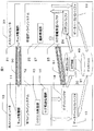
図1は本実施形態のオンライン処理システムの概略構成を示す図である。図1に示す様に本実施形態のホストコンピュータ10は、モニタ処理部11と、ログ出力処理部15と、ログ転送処理部16とを有している。
【0019】
モニタ処理部11は、モニタ処理部21との間で相互監視の為の制御電文を交換し合うことにより相手システムの稼働状態を監視する処理部である。ログ出力処理部15は、ログI/Oバッファ14に格納されているログ情報を実行オンラインシステム12及び待機オンラインシステム22で共用される記憶装置に出力する処理部である。
【0020】
ログ転送処理部16は、実行オンラインシステム12で行われた参照処理の履歴を示す参照履歴と更新処理の履歴を示す更新履歴とを表すログ情報を待機オンラインシステム22に転送する処理部である。
【0021】
ホストコンピュータ10をモニタ処理部11、ログ出力処理部15及びログ転送処理部16として機能させる為のプログラムは、CD−ROM等の記録媒体に記録され磁気ディスク等に格納された後、メモリにロードされて実行されるものとする。なお前記プログラムを記録する記録媒体はCD−ROM以外の他の記録媒体でも良い。
【0022】
ホストコンピュータ20は、モニタ処理部21と、追跡処理部27とを有している。モニタ処理部21は、モニタ処理部11との間で相互監視の為の制御電文を交換し合うことにより、業務処理を実行中の実行オンラインシステム12の稼動状態を監視し、実行オンラインシステム12の障害を検知した場合に、追跡処理の行われたデータベースI/Oバッファ23を用いて前記業務処理を待機オンラインシステム22で続行させる処理部である。
【0023】
追跡処理部27は、前記転送されたログ情報に従って、待機オンラインシステム22内のデータベースI/Oバッファ23の内容を実行オンラインシステム12内のデータベースI/Oバッファ13の内容に一致させる追跡処理を実施する処理部である。
【0024】
ホストコンピュータ20をモニタ処理部21及び追跡処理部27として機能させる為のプログラムは、CD−ROM等の記録媒体に記録され磁気ディスク等に格納された後、メモリにロードされて実行されるものとする。なお前記プログラムを記録する記録媒体はCD−ROM以外の他の記録媒体でも良い。
【0025】
本実施形態のオンライン処理システムは、実行オンライン側のホストコンピュータ10と、実行オンライン側のモニタ処理部11と、実行オンライン側の実行オンラインシステム12(例えばデータベース管理システム)と、待機オンライン側のホストコンピュータ20と、待機オンライン側のモニタ処理部21と、待機オンライン側の待機オンラインシステム22(例えばデータベース管理システム)とを有している。
【0026】
また、実行オンライン側の実行オンラインシステム12と待機オンライン側の待機オンラインシステム22とで共用する不揮発な記憶装置(一般には磁気ディスク装置)上にはログ情報31を格納するログファイル30やデータベース40を有している。
【0027】
更に、本実施形態のオンライン処理システムは、実行オンラインシステム12がデータベース40とのレコードの入出力に使用するデータベースI/Oバッファ13と、実行オンラインシステム12がログファイル30とのログ情報の入出力に使用するログI/Oバッファ14と、待機オンラインシステム22がデータベース40とのレコードの入出力に使用するデータベースI/Oバッファ23と、待機オンラインシステム22がログファイル30とのログ情報の入出力に使用するログI/Oバッファ24とを有している。
【0028】
また、実行オンラインシステム12がログI/Oバッファ14に格納されているログ情報をログファイル30に出力するログ出力処理部15と、実行オンラインシステム12がログI/Oバッファ14に格納されているログ情報を待機オンラインシステム22のログ情報受信バッファ25に転送するログ転送処理部16と、転送されたログ情報に従って、実行オンラインシステム12での業務処理と並行して待機システムでの追跡処理を実施する追跡処理部27と、モニタ処理部11とモニタ処理部21間で相互監視の為の制御電文(Alive電文)を交換しあう為の通信媒体50と、実行オンラインシステム12から待機オンラインシステム22へのログ情報の転送の為の通信媒体51と、待機オンラインシステム22でログファイル30上のログ情報31を入力する為のログI/Oバッファ24とを有している。
【0029】
ここで、通信媒体50と通信媒体51は物理的に一つでも良いが、ログ情報の転送トラフィックが高くなった場合の制御信号の電送遅延による誤動作を防ぐ為に、本実施形態では別々の通信媒体としている。
【0030】
更に、データベースI/Oバッファ13、ログI/Oバッファ14、データベースI/Oバッファ23、ログI/Oバッファ24やログ情報受信バッファ25は、それぞれ一つであっても良いが、性能・信頼性を確保する為に、それぞれ複数面のバッファを持ってバッファリングを行う。
【0031】
また図1では実行オンラインシステム12にログ出力処理部15及びログ転送処理部16を示し、待機オンラインシステム22には追跡処理部27を示しているが、実行オンラインシステム12と待機オンラインシステム22とでは、実装している機能に違いはなく、実行系になるか待機系になるかによって振る舞いが変わるだけであるものとする。
【0032】
よって、ホストコンピュータ10で障害が発生してトランザクションの実行権がホストコンピュータ20に切り替わり、待機オンラインシステム22がトランザクションサービスを開始したら、待機オンラインシステム22が実行系になり、ホストコンピュータ10の障害復旧後は、実行オンラインシステム12が待機系になる。
【0033】
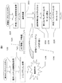
図2は本実施形態の実行オンラインシステム12及び待機オンラインシステム22の処理手順を示すフローチャートである。図2に示す様に本実施形態の実行オンラインシステム12は、起動されるとまず初期設定処理を行う(ステップ122)。
【0034】
この初期設定処理では、処理プログラムのロード、各種の定義情報や実行パラメタの取り込み、仮想記憶上の制御テーブルの作成、データベースのオープン、トランザクション実行空間(実行プロセスとも呼ぶ)の起動等を行い、更に、ログファイルの終端にあるログ情報の検出・記憶を行う。ここでは、更に待機オンラインシステム22とのログ情報転送に関わるバッファの確保・ページ固定・バッファの位置情報の交換等を行う。オンラインシステムでは、この他に端末との通信セッションの確立や切り替え準備等も行われるが、本実施形態の範囲外である為、図1及び図2には示されていない。
【0035】
一方、待機オンラインシステム22でも、待機システムとしての同様な初期設定を行う(ステップ222)。この時点で、モニタ処理部11とモニタ処理部21による相互監視状態が開始される。
【0036】
相互監視状態が開始されると、実行オンラインシステム12では業務トランザクションの処理を行う(ステップ123)。
【0037】
参照処理または更新処理を行う業務トランザクションで取得されたログ情報124が待機オンラインシステム22に転送されると、待機オンラインシステム22では、ログ情報124に従ってメモリ中でトランザクション状態やデータベースのレコードの参照及び更新状態を追跡する(ステップ223)。このとき、ログファイル30やデータベース40は実行オンラインシステム12から更新される為、待機オンラインシステム22では、これらの外部記憶装置への書き込みは行わずに、データベースのインデクスの参照状態やレコードの更新状態の追跡さえも、メモリ中のデータベースI/Oバッファ23上でだけ実施する。
【0038】
実行オンラインシステム12に障害が発生すると(ステップ125)、モニタ処理部11またはモニタ処理部21が障害を検知して、業務トランザクションの実行権を待機オンラインシステム22に切り替える(ステップ126)。
【0039】
実行オンラインシステム12だけの障害に留まっている場合は、モニタ処理部11が障害を検知してモニタ処理部21に通知する。ホストコンピュータ10全体に障害が及んでモニタ処理部11さえ正常に稼動できない場合は、モニタ処理部11からモニタ処理部21への制御電文(Alive電文)が途切れる為、モニタ処理部21が自発的に相手システムである実行オンラインシステム12の障害を検知する。
【0040】
待機オンラインシステム22への切り替えが発生すると、未処理のログ情報124の追跡の完了を待ち合わせた後(ステップ224)、新たな業務トランザクションのサービスを開始する(ステップ225)と共に、並行して未完了トランザクションのロールバック(後退復帰)を行う(ステップ226)。
【0041】
図3は本実施形態の業務トランザクション処理の処理手順を示すフローチャートである。図3を用いて、図2のステップ123の業務トランザクション処理を説明する。
【0042】
トランザクションが開始されると、トランザクションの開始を示すログをログI/Oバッファ14にバッファリングする(ステップ1231)。次に、データベースI/Oバッファ13上でレコードの参照や更新を行う(ステップ1232)と共に、レコードの参照ログや更新ログをログI/Oバッファ14にバッファリングする(ステップ1233)。一つのトランザクションでのデータベースレコードの参照や更新が完了すると、トランザクション終了ログをログI/Oバッファ14にバッファリングし(ステップ1234)、ログファイル30へ未出力のログ情報を強制的に出力する(ステップ1235)。
【0043】
ここで、ステップ1232において、データベースI/Oバッファ13に存在していないデータへの参照が行われた場合に、ステップ1233でその参照ログをログI/Oバッファ14にバッファリングするものとし、ログ情報の出力や転送に必要な負荷を軽減させても良い。
【0044】
図4は本実施形態のログ情報のバッファリング処理の処理手順を示すフローチャートである。図4を用いて、図3のステップ1231、ステップ1233及びステップ1234のログ情報のバッファリング処理を説明する。
【0045】
まず、現在のバッファリング先となっているログI/Oバッファに空きがあるか調べる(ステップ12311)。空きがあれば、該ログI/Oバッファにログ情報を格納する(ステップ12315)。
【0046】
空きがなければ、他のログI/Oバッファに空きがあるか調べる(ステップ12312)。ここで、空きが見つかれば、そのログI/Oバッファを新たなバッファリング先として設定して(ステップ12314)、ログ情報を格納する(ステップ12315)。
【0047】
空きのログI/Oバッファが一つもない場合は、空きができるのを待ち合わせる(ステップ12313)。ここで、空きのログI/Oバッファが一つも無かった場合に、動的に新たなログI/Oバッファを確保する方法もあるが、メモリ不足を引き起こして障害の引き金になる可能性がある為、本実施形態では採用しない。
【0048】
図5は本実施形態の未出力ログの強制出力処理の処理手順を示すフローチャートである。図5を用いて、図3のステップ1235における未出力ログの強制出力処理を説明する。
【0049】
まず、現在のバッファリング先となっているログI/Oバッファを、“空き無し”の状態にして該ログI/Oバッファへの新たなバッファリングを抑止する(ステップ12351)。
【0050】
次に、ログファイル30へまだ出力していないログI/Oバッファを順次出力する(ステップ12352)。この出力は外部記憶装置へのI/O動作が完了するまで制御が戻らない同期書き込み方式でも、I/O動作の完了を待たない非同期書き込み方式でも良いが、本実施形態では、待機オンラインシステム22へのログ情報の転送処理が実行オンラインシステム12のトランザクションへ与える影響を無くす為に、非同期書き込み方式を採用する。
【0051】
ログファイル30への書き込みの完了を待っている間に、前記ステップ12352で対象にしたログI/Oバッファの内容を、通信媒体51を介して待機オンラインシステム22のログ情報受信バッファ25に直接書き込む(ステップ12353)。この書き込み位置等の情報は、前記のステップ122で示した初期設定時点及び前記のステップ123で示した前回の書き込み時の返信情報で把握しておくものとする。
【0052】
ここで、待機オンラインシステム22が稼動していない場合は、前記ステップ12353は失敗するが、実行オンラインシステム12側では成功したものとして扱う。この不整合状態は、待機オンラインシステム22に切り替える際に、その時点の最新のログ情報受信バッファ25のログまでの差分をログファイル30から読み込んで追い付かせることで解消させる。この処理によって、シーソーゲームの様に、実行系と待機系が頻繁に切り替わった場合であっても自動的に追随することができる。
【0053】
次に、前記ステップ12352のI/O動作の完了を待ち合わせる(ステップ12354)。前記ステップ12352及びステップ12353の両方が完了したログI/Oバッファを空きバッファとする(ステップ12355)。
【0054】
図6は本実施形態の追跡処理の処理手順を示すフローチャートである。図6を用いて、図2のステップ223の追跡処理を説明する。
【0055】
まず、待機オンラインシステム22の初期設定処理222時点で記憶したログファイルの終端にあるログ情報と、ログ情報受信バッファ25に送られてきたログ情報を比べる(ステップ22301)。
【0056】
ログ情報が不連続(具体的には、ログファイルの世代番号及びログレコードの集合体であるログブロックの通番からなる番号が不連続であり、途中のブロックが抜けている状態)であれば、ログファイル30からログ情報31を入力して、ログ情報受信バッファ25の時点まで追い付かせる(ステップ22302)。ここでの追い付き処理の具体的な方法は、後述のステップ22303〜ステップ22308と同様である。
【0057】
次に、ログ情報受信バッファ25に格納された個々のログ情報を順次調べ、トランザクションの開始ログや終了ログの様にトランザクションの状態の変更を記録したログであれば(ステップ22303)、メモリ中のトランザクション毎の管理情報を更新する(ステップ22304)。
【0058】
データベースのレコードの参照ログまたは更新ログであれば(ステップ22305)、データベースI/Oバッファ23に該当するページがあるかを調べ(ステップ22306)、データベースI/Oバッファ23に該レコードのページがなければデータベース40からデータベースI/Oバッファ23に該レコードのページを読み込む(ステップ22307)。次に、該ログが更新ログの場合にはその内容に従ってデータベースI/Oバッファ23上でレコードを更新する(ステップ22308)。
【0059】
これらステップ22303〜ステップ22308の処理を、ログ情報受信バッファ25にある全てのログ情報に対して繰り返す(ステップ22309)。
【0060】
次に、モニタ処理部11またはモニタ処理部21から障害の検知が通知されているかを確認し、自システムが待機システムのままかどうかを調べる(ステップ22310)。待機システムのままであれば、ログ情報の受信を待って(ステップ22313)、前記ステップ22303〜ステップ22308の処理を繰り返す。一方、モニタ処理部11またはモニタ処理部21による障害の検知により実行システムへの切り替えが指示されていれば、実行システムとして業務トランザクション処理を実行する。
【0061】
以上説明した様に本実施形態のオンライン処理システムによれば、実行オンラインシステムで障害が発生した場合に、実行オンラインシステムの入出力バッファの内容に予め一致させておいた待機オンラインシステムの入出力バッファを用いて待機オンラインシステムで業務処理を続行させるので、実行オンラインシステムの障害発生時に待機オンラインシステムへの切り替えを高速に行うことが可能である。
【0062】
また本実施形態のオンライン処理システムによれば、実行オンラインシステムの入出力バッファに存在していないデータへの参照処理が行われた場合にその参照履歴をログ情報として待機オンラインシステムに転送するので、待機オンラインシステム内の入出力バッファの内容を実行オンラインシステム内の入出力バッファの内容に一致させる為のログ情報の転送負荷を軽減することが可能である。
【0063】
また本実施形態のオンライン処理システムによれば、追跡処理の行われたログ情報と実行オンラインシステムから転送されたログ情報とが連続していない場合に、その間のログ情報を記憶装置から読み出して、待機オンラインシステム内の入出力バッファの追付き処理を行うので、待機オンラインシステムが障害や保守の後に再稼働した場合に、実行オンラインシステムでの業務処理の実行に影響を与えることなくホットスタンバイ状態の再確立を行うことが可能である。
【0064】
【発明の効果】
本発明によれば実行オンラインシステムで障害が発生した場合に、実行オンラインシステムの入出力バッファの内容に予め一致させておいた待機オンラインシステムの入出力バッファを用いて待機オンラインシステムで業務処理を続行させるので、実行オンラインシステムの障害発生時に待機オンラインシステムへの切り替えを高速に行うことが可能である。
【図面の簡単な説明】
【図1】本実施形態のオンライン処理システムの概略構成を示す図である。
【図2】本実施形態の実行オンラインシステム12及び待機オンラインシステム22の処理手順を示すフローチャートである。
【図3】本実施形態の業務トランザクション処理の処理手順を示すフローチャートである。
【図4】本実施形態のログ情報のバッファリング処理の処理手順を示すフローチャートである。
【図5】本実施形態の未出力ログの強制出力処理の処理手順を示すフローチャートである。
【図6】本実施形態の追跡処理の処理手順を示すフローチャートである。
【符号の説明】
10…ホストコンピュータ、12…実行オンラインシステム、13…データベースI/Oバッファ、14…ログI/Oバッファ、20…ホストコンピュータ、22…待機オンラインシステム、23…データベースI/Oバッファ、24…ログI/Oバッファ、25…ログ情報受信バッファ、30…ログファイル、31…ログ情報、40…データベース、50及び51…通信媒体、11…モニタ処理部、15…ログ出力処理部、16…ログ転送処理部、21…モニタ処理部、27…追跡処理部、124…ログ情報。[0001]
BACKGROUND OF THE INVENTION
The present invention relates to an online processing system that requires high-speed recovery processing accompanying a system stop, and more particularly to a technique that is effective when applied to an online processing system such as an online database system in which a large number of update transactions occur.
[0002]
[Prior art]
In a conventional general online system recovery method, log information, which is history information necessary for system recovery, is stored on an external storage device by the execution online system for recovery processing when the execution online system stops due to a failure. When a failure occurs in the execution online system, which is stored in the log file, the standby online system reads the log information and executes processing necessary for system recovery.
[0003]
As this speed-up technology, for example, the one described in Japanese Patent Application Laid-Open No. 62-57030 is known, and the outline is that log information on an external storage device shared between host computers is recorded before the occurrence of a failure. By reading by the standby online system and tracking the processing before the standby online system stops, the amount of log information read when a failure occurs is reduced.
[0004]
In addition, as described in Japanese Patent Laid-Open No. 2-77743, log information is stored in a log file on an external storage device shared between host computers in an execution online system, and is also stored in an extended storage device shared between host computers. Is also stored at the same time, and in the system recovery process in the standby online system after a failure occurs in the execution online system, the log information is read from this extended storage device, thereby eliminating the reading of the log information from the external storage device It has been known.
[0005]
Further, as described in Japanese Patent Laid-Open No. 10-49418, log information of the execution online system is transferred to the standby online system by communication, and the tracking process is performed in the standby online system before switching due to a failure occurs. Thus, there is known a method for speeding up recovery after a failure occurs.
[0006]
[Problems to be solved by the invention]
However, the technique described in Japanese Patent Application Laid-Open No. 62-57030 needs to input log information after a checkpoint from a log file on an external storage device after switching to a standby online system due to a failure. Depending on the interval between checkpoints, a large amount of log information is read, which is a major factor that hinders high-speed system recovery. On the other hand, if the interval between checkpoints is reduced in order to reduce the amount of log information to be read after switching due to a failure, there is a problem of increasing the overhead in the execution online system.
[0007]
Although the technique described in Japanese Patent Laid-Open No. 2-77743 speeds up the reading of log information, as with the technique described in Japanese Patent Laid-Open No. 62-57030, switching to a standby online system due to a failure is performed. After this occurs, it is necessary to read log information after the checkpoint, and depending on the interval between checkpoints, a large amount of log information is read, which is a major factor that hinders the realization of high-speed system recovery. On the other hand, if the interval between checkpoints is reduced in order to reduce the amount of log information to be read after switching due to a failure, there is a problem of increasing the overhead in the execution online system.
[0008]
In addition, the technology described in Japanese Patent Laid-Open No. 10-49418 transfers log information of an execution online system to the standby online system by communication, and performs tracking processing in the standby online system before switching due to a failure occurs. However, since the tracking process is performed using only the log information of the update history, the result of the reference process such as the reference to the index performed in the execution online system is not reflected in the memory of the standby online system. However, there is a problem that the efficiency of reference processing such as index search is reduced when switching due to a failure occurs. In addition, since external storage devices such as log files and databases are not shared, there is a problem that twice as many external storage devices are required, and once the redundant configuration collapses due to a failure on the standby online system side, etc., the redundant configuration There is a problem in that continuous operation cannot be realized for 24 hours 365 days because it is necessary to suspend the execution of the transaction for the purpose of consistency when returning to the system.
[0009]
An object of the present invention is to provide a technique capable of solving the above-described problem and switching to a standby online system at a high speed when a failure occurs in an execution online system.
[0010]
Another object of the present invention is to provide a technique capable of reducing the transfer load of log information for matching the contents of the input / output buffer in the standby online system with the contents of the input / output buffer in the execution online system. It is in.
[0011]
Another object of the present invention is a technology capable of re-establishing a hot standby state without affecting the execution of business processing in the execution online system when the standby online system is restarted after failure or maintenance. Is to provide.
[0012]
[Means for Solving the Problems]
The present invention relates to the contents of the input / output buffer of the execution online system when a failure occurs in the execution online system in the online processing system that switches the business process to the standby online system and continues when the failure occurs in the execution online system. Business processing is continued in the standby online system using the input / output buffer of the standby online system that has been matched in advance.
[0013]
In the present invention, log information representing the reference history indicating the history of the reference processing performed in the execution online system and the update history indicating the history of the update processing during the execution of the execution online system is transferred to the standby online system, and the log In the standby online system that has received the information, in accordance with the transferred log information, processing corresponding to the reference processing and update processing performed in the input / output buffer of the execution online system is performed on the input / output buffer of the standby online system, A tracking process is executed to match the contents of the input / output buffer in the standby online system with the contents of the input / output buffer in the execution online system.
[0014]
In addition, the operational status of the execution online system that is executing the business process is monitored, and when a failure of the execution online system is detected, the business process is waited for using the input / output buffer that has been subjected to the tracking process. To continue.
[0015]
As described above, according to the present invention, an online system with less overhead in the execution online system while eliminating the input of log information from the log file on the external storage device after the switch to the standby online system due to a failure occurs. Recovery method can be realized.
[0016]
As described above, according to the online processing system of the present invention, when a failure occurs in the execution online system, the input / output buffer of the standby online system that has been matched in advance with the contents of the input / output buffer of the execution online system is used. Since the business processing is continued in the standby online system, it is possible to switch to the standby online system at high speed when a failure occurs in the execution online system.
[0017]
DETAILED DESCRIPTION OF THE INVENTION
The following describes an online processing system according to an embodiment that switches business processing to a standby online system and continues when a failure occurs in the execution online system.
[0018]
FIG. 1 is a diagram showing a schematic configuration of an online processing system according to the present embodiment. As shown in FIG. 1, the
[0019]
The
[0020]
The log
[0021]
A program for causing the
[0022]
The
[0023]
The
[0024]
A program for causing the
[0025]
The online processing system according to the present embodiment includes an execution
[0026]
A
[0027]
Furthermore, the online processing system according to the present embodiment includes the database I /
[0028]
The execution
[0029]
Here, the
[0030]
Further, the database I /
[0031]
1 shows the log
[0032]
Therefore, when a failure occurs in the
[0033]
FIG. 2 is a flowchart showing a processing procedure of the execution
[0034]
In this initial setting process, loading of processing programs, importing various definition information and execution parameters, creating a control table in virtual memory, opening a database, starting a transaction execution space (also called an execution process), etc. The log information at the end of the log file is detected and stored. Here, buffer reservation, page fixing, buffer position information exchange, and the like related to log information transfer with the standby
[0035]
On the other hand, the standby
[0036]
When the mutual monitoring state is started, the execution
[0037]
When the
[0038]
When a failure occurs in the execution online system 12 (step 125), the
[0039]
When the failure remains only in the execution
[0040]
When switching to the standby
[0041]
FIG. 3 is a flowchart showing a processing procedure of business transaction processing according to the present embodiment. The business transaction process in
[0042]
When the transaction is started, a log indicating the start of the transaction is buffered in the log I / O buffer 14 (step 1231). Next, the record is referred to and updated on the database I / O buffer 13 (step 1232), and the record reference log and update log are buffered in the log I / O buffer 14 (step 1233). When the reference or update of the database record in one transaction is completed, the transaction end log is buffered in the log I / O buffer 14 (step 1234), and log information not yet output is forcibly output to the log file 30 (step 1234). Step 1235).
[0043]
Here, when reference is made to data that does not exist in the database I /
[0044]
FIG. 4 is a flowchart showing a processing procedure of log information buffering processing according to this embodiment. The log information buffering process in
[0045]
First, it is checked whether or not there is a free space in the log I / O buffer that is the current buffering destination (step 12311). If there is a vacancy, the log information is stored in the log I / O buffer (step 12315).
[0046]
If there is no space, it is checked whether there is space in another log I / O buffer (step 12312). If a free space is found, the log I / O buffer is set as a new buffering destination (step 12314), and log information is stored (step 12315).
[0047]
If there is no empty log I / O buffer, the system waits for an empty space (step 12313). Here, there is a method of dynamically securing a new log I / O buffer when there is no empty log I / O buffer, but it may cause a memory shortage and trigger a failure. Therefore, it is not adopted in this embodiment.
[0048]
FIG. 5 is a flowchart showing a processing procedure of the unoutput log forcible output processing of this embodiment. The unoutput log forcible output process in
[0049]
First, the log I / O buffer that is the current buffering destination is set to a “no space” state, and new buffering to the log I / O buffer is suppressed (step 12351).
[0050]
Next, log I / O buffers that have not been output to the
[0051]
While waiting for completion of writing to the
[0052]
Here, when the standby
[0053]
Next, the completion of the I / O operation in
[0054]
FIG. 6 is a flowchart showing the processing procedure of the tracking process of this embodiment. The tracking process in
[0055]
First, the log information at the end of the log file stored at the time of the
[0056]
If the log information is discontinuous (specifically, the log file generation number and the log block serial number that is an aggregate of log records are discontinuous, and the intermediate block is missing) The
[0057]
Next, the individual log information stored in the log
[0058]
If it is a reference log or update log of a database record (step 22305), it is checked whether there is a corresponding page in the database I / O buffer 23 (step 22306), and there is no page of the record in the database I /
[0059]
The processes in
[0060]
Next, it is checked whether or not the detection of the failure is notified from the
[0061]
As described above, according to the online processing system of this embodiment, when a failure occurs in the execution online system, the input / output buffer of the standby online system that has been matched in advance with the contents of the input / output buffer of the execution online system. Since the business process is continued in the standby online system using the system, it is possible to switch to the standby online system at a high speed when a failure occurs in the execution online system.
[0062]
Further, according to the online processing system of the present embodiment, when reference processing to data that does not exist in the input / output buffer of the execution online system is performed, the reference history is transferred to the standby online system as log information. It is possible to reduce the transfer load of log information for matching the contents of the input / output buffer in the standby online system with the contents of the input / output buffer in the execution online system.
[0063]
Further, according to the online processing system of the present embodiment, when the log information subjected to the tracking process and the log information transferred from the execution online system are not continuous, the log information between them is read from the storage device, Since the I / O buffer in the standby online system is added, if the standby online system is restarted after a failure or maintenance, the hot standby state is not affected without affecting the execution of business processing in the execution online system. Re-establishment is possible.
[0064]
【The invention's effect】
According to the present invention, when a failure occurs in the execution online system, business processing is continued in the standby online system using the input / output buffer of the standby online system that has been matched in advance with the contents of the input / output buffer of the execution online system. Therefore, when a failure occurs in the execution online system, it is possible to switch to the standby online system at high speed.
[Brief description of the drawings]
FIG. 1 is a diagram showing a schematic configuration of an online processing system according to an embodiment.
FIG. 2 is a flowchart showing a processing procedure of the execution
FIG. 3 is a flowchart showing a processing procedure of business transaction processing according to the present embodiment.
FIG. 4 is a flowchart illustrating a processing procedure of log information buffering processing according to the present exemplary embodiment.
FIG. 5 is a flowchart showing a processing procedure for forced output processing of a non-output log according to the present embodiment.
FIG. 6 is a flowchart showing a processing procedure of tracking processing according to the present embodiment.
[Explanation of symbols]
DESCRIPTION OF
Claims (7)
実行システムで行われた参照処理の履歴を示す参照履歴と更新処理の履歴を示す更新履歴とを表すログ情報を待機システムに転送するステップと、
前記転送されたログ情報に従って、待機システム内の入出力バッファの内容を実行システム内の入出力バッファの内容に一致させる追跡処理を実施するステップと、
業務処理を実行中の実行システムの稼動状態を監視し、実行システムの障害を検知した場合に、前記追跡処理の行われた入出力バッファを用いて前記業務処理を待機システムで続行させるステップとを有し、
前記ログ情報として待機システムに転送される参照履歴は、実行システムの入出力バッファに存在していないデータへの参照処理の履歴を示すものであることを特徴とするシステム回復方法。In the system recovery method of switching the business process to the standby system and continuing if a failure occurs in the execution system,
Transferring log information representing a reference history indicating a history of reference processing performed in the execution system and an update history indicating a history of update processing to the standby system;
Performing a tracking process to match the contents of the input / output buffer in the standby system with the contents of the input / output buffer in the execution system according to the transferred log information;
Monitoring the operating state of the execution system that is executing the business process, and, when a failure of the execution system is detected, using the input / output buffer that has been subjected to the tracking process to continue the business process in a standby system; Yes, and
The reference history to be transferred to the standby system as the log information, system recovery method comprising der Rukoto shows the history of reference processing to the data that is not present in the output buffer of the running system.
実行システムで行われた参照処理の履歴を示す参照履歴と更新処理の履歴を示す更新履歴とを表すログ情報を待機システムに転送するログ転送処理部と、
前記転送されたログ情報に従って、待機システム内の入出力バッファの内容を実行システム内の入出力バッファの内容に一致させる追跡処理を実施する追跡処理部と、
業務処理を実行中の実行システムの稼動状態を監視し、実行システムの障害を検知した場合に、前記追跡処理の行われた入出力バッファを用いて前記業務処理を待機システムで続行させるモニタ処理部とを備え、
前記ログ情報として待機システムに転送される参照履歴は、実行システムの入出力バッファに存在していないデータへの参照処理の履歴を示すものであることを特徴とする計算機システム。In a computer system that switches business processing to a standby system and continues when a failure occurs in the execution system,
A log transfer processing unit that transfers log information representing a reference history indicating a history of reference processing performed in the execution system and an update history indicating a history of update processing to the standby system;
A tracking processing unit for performing a tracking process for matching the contents of the input / output buffer in the standby system with the contents of the input / output buffer in the execution system according to the transferred log information;
A monitor processing unit that monitors the operating state of an execution system that is executing a business process and, when a failure of the execution system is detected, uses the input / output buffer that has been subjected to the tracking process to continue the business process in a standby system And
The reference history to be transferred to the standby system as the log information, computer system, characterized in der Rukoto shows the history of reference processing to the data that is not present in the output buffer of the running system.
前記プログラムは、実行システムで行われた参照処理の履歴を示す参照履歴と更新処理の履歴を示す更新履歴とを表すログ情報を待機システムに転送するステップと、
前記転送されたログ情報に従って、待機システム内の入出力バッファの内容を実行システム内の入出力バッファの内容に一致させる追跡処理を実施するステップと、
業務処理を実行中の実行システムの稼動状態を監視し、実行システムの障害を検知した場合に、前記追跡処理の行われた入出力バッファを用いて前記業務処理を待機システムで続行させるステップとを有し、
前記ログ情報として待機システムに転送される参照履歴は、実行システムの入出力バッファに存在していないデータへの参照処理の履歴を示すものであるシステム回復方法を実現させるためのプログラムを記録したことを特徴とするコンピュータ読み取り可能な記録媒体。In a computer-readable recording medium recording a program for realizing a system recovery method for switching a business process to a standby system and continuing when a failure occurs in the execution system,
The program transfers log information representing a reference history indicating a history of reference processing performed in the execution system and an update history indicating a history of update processing to the standby system;
Performing a tracking process to match the contents of the input / output buffer in the standby system with the contents of the input / output buffer in the execution system according to the transferred log information;
Monitoring the operating state of the execution system that is executing the business process, and, when a failure of the execution system is detected, using the input / output buffer that has been subjected to the tracking process to continue the business process in a standby system; Yes, and
The reference history to be transferred to the standby system as the log information, recording a program for realizing the Der Ru system recovery method indicates the reference processing of the history for data that is not present in the output buffer of the running system A computer-readable recording medium.
実行システムで行われた参照処理の履歴を示す参照履歴と更新処理の履歴を示す更新履歴とを表すログ情報を待機システムに転送するステップと、
前記転送されたログ情報に従って、待機システム内の入出力バッファの内容を実行システム内の入出力バッファの内容に一致させる追跡処理を実施するステップとを有し、
前記ログ情報として待機システムに転送される参照履歴は、実行システムの入出力バッファに存在していないデータへの参照処理の履歴を示すものであることを特徴とするシステム回復方法。In the system recovery method of switching the business process to the standby system and continuing if a failure occurs in the execution system,
Transferring log information representing a reference history indicating a history of reference processing performed in the execution system and an update history indicating a history of update processing to the standby system;
Wherein according to the transfer log information, possess and performing a tracking process to match the contents of the input and output buffers in the execution system the contents of the output buffer in the standby system,
The reference history to be transferred to the standby system as the log information, system recovery method comprising der Rukoto shows the history of reference processing to the data that is not present in the output buffer of the running system.
Priority Applications (3)
| Application Number | Priority Date | Filing Date | Title |
|---|---|---|---|
| JP2000381623A JP3877519B2 (en) | 2000-12-15 | 2000-12-15 | System recovery method, computer system for implementing the method, and recording medium recording the processing program |
| US10/012,437 US20020078207A1 (en) | 2000-12-15 | 2001-12-12 | Online system recovery system, method and program |
| US11/282,717 US20060089975A1 (en) | 2000-12-15 | 2005-11-21 | Online system recovery system, method and program |
Applications Claiming Priority (1)
| Application Number | Priority Date | Filing Date | Title |
|---|---|---|---|
| JP2000381623A JP3877519B2 (en) | 2000-12-15 | 2000-12-15 | System recovery method, computer system for implementing the method, and recording medium recording the processing program |
Related Child Applications (1)
| Application Number | Title | Priority Date | Filing Date |
|---|---|---|---|
| JP2006258953A Division JP2007018534A (en) | 2006-09-25 | 2006-09-25 | Online system recovery method, implementation device thereof, and recording medium in which processing program thereof is recorded |
Publications (3)
| Publication Number | Publication Date |
|---|---|
| JP2002183088A JP2002183088A (en) | 2002-06-28 |
| JP2002183088A5 JP2002183088A5 (en) | 2004-08-26 |
| JP3877519B2 true JP3877519B2 (en) | 2007-02-07 |
Family
ID=18849590
Family Applications (1)
| Application Number | Title | Priority Date | Filing Date |
|---|---|---|---|
| JP2000381623A Expired - Fee Related JP3877519B2 (en) | 2000-12-15 | 2000-12-15 | System recovery method, computer system for implementing the method, and recording medium recording the processing program |
Country Status (2)
| Country | Link |
|---|---|
| US (2) | US20020078207A1 (en) |
| JP (1) | JP3877519B2 (en) |
Cited By (1)
| Publication number | Priority date | Publication date | Assignee | Title |
|---|---|---|---|---|
| JP2007018534A (en) * | 2006-09-25 | 2007-01-25 | Hitachi Ltd | Online system recovery method, implementation device thereof, and recording medium in which processing program thereof is recorded |
Families Citing this family (18)
| Publication number | Priority date | Publication date | Assignee | Title |
|---|---|---|---|---|
| US6948008B2 (en) * | 2002-03-12 | 2005-09-20 | Intel Corporation | System with redundant central management controllers |
| US8121978B2 (en) * | 2002-11-15 | 2012-02-21 | Sybase, Inc. | Database system providing improved methods for data replication |
| US7457829B2 (en) * | 2003-06-23 | 2008-11-25 | Microsoft Corporation | Resynchronization of multiple copies of a database after a divergence in transaction history |
| US7299378B2 (en) * | 2004-01-15 | 2007-11-20 | Oracle International Corporation | Geographically distributed clusters |
| JP4368716B2 (en) * | 2004-03-25 | 2009-11-18 | Necエレクトロニクス株式会社 | Communication circuit and communication method |
| US7281153B2 (en) * | 2004-04-14 | 2007-10-09 | International Business Machines Corporation | Apparatus, system, and method for transactional peer recovery in a data sharing clustering computer system |
| US7870426B2 (en) * | 2004-04-14 | 2011-01-11 | International Business Machines Corporation | Apparatus, system, and method for transactional peer recovery in a data sharing clustering computer system |
| JP4490745B2 (en) * | 2004-06-29 | 2010-06-30 | 株式会社日立製作所 | Hot standby system |
| US7788665B2 (en) * | 2006-02-28 | 2010-08-31 | Microsoft Corporation | Migrating a virtual machine that owns a resource such as a hardware device |
| JP4946459B2 (en) * | 2007-01-26 | 2012-06-06 | 三菱電機株式会社 | Satellite-mounted control device |
| WO2008129620A1 (en) * | 2007-04-09 | 2008-10-30 | Fujitsu Limited | Complete dual system, system control method, and system control program |
| JP2009211620A (en) * | 2008-03-06 | 2009-09-17 | Hitachi Information Systems Ltd | Virtual environment duplicating method, system, and program |
| JP5028304B2 (en) * | 2008-03-11 | 2012-09-19 | 株式会社日立製作所 | Virtual computer system and control method thereof |
| JP5703860B2 (en) * | 2011-03-09 | 2015-04-22 | 日本電気株式会社 | Fault tolerant system, memory control method, and program |
| JP5702652B2 (en) * | 2011-04-05 | 2015-04-15 | 日本電信電話株式会社 | Memory synchronization method, active virtual machine, standby virtual machine, and memory synchronization program |
| JP6248747B2 (en) * | 2014-03-28 | 2017-12-20 | 富士通株式会社 | Information processing apparatus, control method, and control program |
| US9870266B2 (en) * | 2015-07-30 | 2018-01-16 | Nasdaq, Inc. | Background job processing framework |
| JP6553125B2 (en) * | 2017-06-20 | 2019-07-31 | 株式会社東芝 | Database server, database management method, and program |
Family Cites Families (11)
| Publication number | Priority date | Publication date | Assignee | Title |
|---|---|---|---|---|
| US4740969A (en) * | 1986-06-27 | 1988-04-26 | Hewlett-Packard Company | Method and apparatus for recovering from hardware faults |
| JPS6375963A (en) * | 1986-09-19 | 1988-04-06 | Hitachi Ltd | System recovery system |
| JPH01147727A (en) * | 1987-12-04 | 1989-06-09 | Hitachi Ltd | Fault restoring method for on-line program |
| US5307481A (en) * | 1990-02-28 | 1994-04-26 | Hitachi, Ltd. | Highly reliable online system |
| US5136498A (en) * | 1990-09-26 | 1992-08-04 | Honeywell Inc. | Method for enacting failover of a 1:1 redundant pair of slave processors |
| JP3085085B2 (en) * | 1994-05-09 | 2000-09-04 | 三菱電機株式会社 | Data access device and distributed database system |
| US5987621A (en) * | 1997-04-25 | 1999-11-16 | Emc Corporation | Hardware and software failover services for a file server |
| US6014757A (en) * | 1997-12-19 | 2000-01-11 | Bull Hn Information Systems Inc. | Fast domain switch and error recovery in a secure CPU architecture |
| US6311288B1 (en) * | 1998-03-13 | 2001-10-30 | Paradyne Corporation | System and method for virtual circuit backup in a communication network |
| JP3763992B2 (en) * | 1999-03-30 | 2006-04-05 | 富士通株式会社 | Data processing apparatus and recording medium |
| US6742136B2 (en) * | 2000-12-05 | 2004-05-25 | Fisher-Rosemount Systems Inc. | Redundant devices in a process control system |
-
2000
- 2000-12-15 JP JP2000381623A patent/JP3877519B2/en not_active Expired - Fee Related
-
2001
- 2001-12-12 US US10/012,437 patent/US20020078207A1/en not_active Abandoned
-
2005
- 2005-11-21 US US11/282,717 patent/US20060089975A1/en not_active Abandoned
Cited By (1)
| Publication number | Priority date | Publication date | Assignee | Title |
|---|---|---|---|---|
| JP2007018534A (en) * | 2006-09-25 | 2007-01-25 | Hitachi Ltd | Online system recovery method, implementation device thereof, and recording medium in which processing program thereof is recorded |
Also Published As
| Publication number | Publication date |
|---|---|
| US20020078207A1 (en) | 2002-06-20 |
| US20060089975A1 (en) | 2006-04-27 |
| JP2002183088A (en) | 2002-06-28 |
Similar Documents
| Publication | Publication Date | Title |
|---|---|---|
| JP3877519B2 (en) | System recovery method, computer system for implementing the method, and recording medium recording the processing program | |
| JP4301849B2 (en) | Information processing method and its execution system, its processing program, disaster recovery method and system, storage device for executing the processing, and its control processing method | |
| US7529950B2 (en) | Information processing system, control method for information processing system, and storage system | |
| US9383928B2 (en) | Replication techniques with content addressable storage | |
| EP2062139B1 (en) | Method for improving transfer of event logs for replication of executing programs | |
| EP3726365B1 (en) | Data processing method and device | |
| JP4282030B2 (en) | Data duplex control method and duplex storage subsystem | |
| WO2018010501A1 (en) | Global transaction identifier (gtid) synchronization method, apparatus and system, and storage medium | |
| JP5365128B2 (en) | Information system, method, and program related to data registered in batch | |
| US10983709B2 (en) | Methods for improving journal performance in storage networks and devices thereof | |
| JPH10326220A (en) | File system and file managing method | |
| CN110413689B (en) | Multi-node data synchronization method and device for memory database | |
| WO2022033269A1 (en) | Data processing method, device and system | |
| JPH10133927A (en) | Computer system and file managing method | |
| JP2008310591A (en) | Cluster system, computer, and failure recovery method | |
| JP2007018534A (en) | Online system recovery method, implementation device thereof, and recording medium in which processing program thereof is recorded | |
| CN113296899A (en) | Transaction master machine, transaction slave machine and transaction processing method based on distributed system | |
| JP7073737B2 (en) | Communication log recording device, communication log recording method, and communication log recording program | |
| US10656867B2 (en) | Computer system, data management method, and data management program | |
| JPH1185594A (en) | Information processing system for remote copy | |
| JP4305328B2 (en) | Computer system and system switching control method using the same | |
| JP2003099208A (en) | Method for data transfer between disk arrays and disk array system | |
| JP6802304B2 (en) | Storage control device, storage control system, storage control method, and storage control program | |
| JP4193754B2 (en) | Data duplication method and program | |
| JP2856150B2 (en) | Transaction history recording system |
Legal Events
| Date | Code | Title | Description |
|---|---|---|---|
| A977 | Report on retrieval |
Free format text: JAPANESE INTERMEDIATE CODE: A971007 Effective date: 20060425 |
|
| A131 | Notification of reasons for refusal |
Free format text: JAPANESE INTERMEDIATE CODE: A131 Effective date: 20060725 |
|
| A521 | Written amendment |
Free format text: JAPANESE INTERMEDIATE CODE: A523 Effective date: 20060925 |
|
| TRDD | Decision of grant or rejection written | ||
| A01 | Written decision to grant a patent or to grant a registration (utility model) |
Free format text: JAPANESE INTERMEDIATE CODE: A01 Effective date: 20061024 |
|
| A61 | First payment of annual fees (during grant procedure) |
Free format text: JAPANESE INTERMEDIATE CODE: A61 Effective date: 20061031 |
|
| R150 | Certificate of patent or registration of utility model |
Free format text: JAPANESE INTERMEDIATE CODE: R150 |
|
| FPAY | Renewal fee payment (event date is renewal date of database) |
Free format text: PAYMENT UNTIL: 20101110 Year of fee payment: 4 |
|
| FPAY | Renewal fee payment (event date is renewal date of database) |
Free format text: PAYMENT UNTIL: 20101110 Year of fee payment: 4 |
|
| FPAY | Renewal fee payment (event date is renewal date of database) |
Free format text: PAYMENT UNTIL: 20111110 Year of fee payment: 5 |
|
| FPAY | Renewal fee payment (event date is renewal date of database) |
Free format text: PAYMENT UNTIL: 20111110 Year of fee payment: 5 |
|
| FPAY | Renewal fee payment (event date is renewal date of database) |
Free format text: PAYMENT UNTIL: 20121110 Year of fee payment: 6 |
|
| FPAY | Renewal fee payment (event date is renewal date of database) |
Free format text: PAYMENT UNTIL: 20121110 Year of fee payment: 6 |
|
| FPAY | Renewal fee payment (event date is renewal date of database) |
Free format text: PAYMENT UNTIL: 20131110 Year of fee payment: 7 |
|
| LAPS | Cancellation because of no payment of annual fees |