JP3876294B2 - Boom control device for boom type work vehicle - Google Patents
Boom control device for boom type work vehicle Download PDFInfo
- Publication number
- JP3876294B2 JP3876294B2 JP25839496A JP25839496A JP3876294B2 JP 3876294 B2 JP3876294 B2 JP 3876294B2 JP 25839496 A JP25839496 A JP 25839496A JP 25839496 A JP25839496 A JP 25839496A JP 3876294 B2 JP3876294 B2 JP 3876294B2
- Authority
- JP
- Japan
- Prior art keywords
- hydraulic
- boom
- signal
- source
- actuator
- Prior art date
- Legal status (The legal status is an assumption and is not a legal conclusion. Google has not performed a legal analysis and makes no representation as to the accuracy of the status listed.)
- Expired - Fee Related
Links
Images


Description
【0001】
【発明の属する技術分野】
この発明は、ブーム式作業車のブーム制御装置に関するものである。
【0002】
【従来の技術】
高所作業車やクレーン車等のブーム式作業車においては、そのブームを油圧により駆動するものがあり、そのブームの駆動はブーム駆動用油圧回路により行なわれる。
【0003】
ところで、近時、ブームの移動速度を自動的に制御するために、その油圧回路中に設置された油圧アクチュエータに加わる油圧を電磁比例制御弁等の油圧制御手段を用いてその流量を電気的に調整することが行なわれている。
【0004】
一方で、この種のブーム式作業車においては、ブーム駆動用油圧回路の油圧源として吐出性能の異なる複数の油圧ポンプを有し、これらの油圧ポンプを選択的に用いるものがある。
【0005】
これは、例えば、作業車の走行用エンジンのPTO軸により駆動する油圧ポンプと、走行用エンジンとは別に装備された,エンジンと油圧ポンプとからなる低騒音型エンジンユニットや、あるいは電動モータで駆動される油圧ポンプユニット等とを装備したブーム式作業車での作業において、その作業現場での環境等の状況に応じてこれらの使い分け等をするためである。
【0006】
しかしながら、従来のこのようなブーム式作業車においては、ブーム駆動用油圧回路が単一であることから、前記油圧源のいかんにかかわらず,電磁比例制御弁等の油圧制御手段による制御目標値が共通に設定されている。
【0007】
【発明が解決しようとする課題】
このような従来のブーム式作業車においては、いずれの油圧源を接続した状態でもともに良好にブームの速度制御をすることができず、少なくとも一方の油圧源と接続した状態でのブームの操作性が幾分損なわれた状態とならざるをえなかった。
【0008】
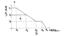
例えば、従来のブーム式作業車においては、吐出量が多く走行用エンジンのPTO軸で駆動される油圧ポンプによる場合のブームの移動速度(図9の線A参照)と、吐出量が比較的少ないモータユニットの油圧ポンプによる場合のブームの移動速度(図9の線B参照)とは、油圧制御手段による減速開始位置R1や減速完了位置R2あるいは停止作動位置R5を同一としても停止作動時のブームの移動速度が異なるので、結局ブームの停止位置R6,R6'にずれを生じる。
【0009】
このようなずれは、例えば線Aによる性能を基準としていた場合に停止位置がR6'であると本来の停止位置R6までの性能をフルに生かすことができず、停止位置R6'から停止位置R6までの間を更に操作することが必要となり作業効率が低くなる。また、逆に、線Bによる性能を基準としていた場合に停止位置がR6であると本来の停止位置R6’をオーバーランすることになるので不都合である。
【0010】
第1の発明は、このような事情に基づいてなされたもので、ブーム駆動用油圧回路に吐出性能が異なる複数の油圧源を有する,この種のブーム式作業車において、いずれの油圧源がブーム駆動用油圧回路に接続された場合にも、ブームの操作性を良好にすることを課題とするものである。
また、第2の発明は、走行用エンジンにより駆動されてそのアクセル開度毎に吐出性能が異なるために別個の油圧源として取り扱われる油圧源を有するブーム式作業車においても、ブームの操作性を良好にすることを課題とするものである。
【0011】
【課題を解決するための手段】
この第1の課題を解決するために、請求項1に記載の発明は、 車体上に少なくとも起伏自在なブームと、このブームを駆動する油圧アクチュエータと、吐出性能が異なりこの油圧アクチュエータに圧油を供給する複数の油圧源と、この複数の油圧源からの圧油を前記アクチュエータに供給するときに圧油を制御する油圧制御手段と、前記ブームの駆動速度を指示する操作レバーの操作量を検出して操作量信号を出力する操作量信号出力手段と、前記ブームの姿勢を検出して姿勢検出信号を出力する姿勢検出手段と、前記複数の油圧源のうち作動している油圧源を検出して油圧源検出信号を出力する油圧源検出手段と、吐出性能が異なる油圧源に対応してそれぞれ異なる補正係数がブームの移動速度を一致させるために定められかつ前記姿勢検出信号と前記操作量信号と前記油圧源検出信号とが入力されしかも該油圧源検出信号に基づき作動している油圧源に対応して定められている補正係数を用いて前記操作量信号を補正することにより得られた制御用信号を出力して前記油圧制御手段を制御する処理部と、を備えていることを特徴とするブーム式作業車のブーム制御装置である。
この第2の課題を解決するために、請求項2に記載の発明は、 車体上に少なくとも起伏自在なブームと、このブームを駆動する油圧アクチュエータと、この油圧アクチュエータに圧油を供給するに際して走行エンジンにより駆動されてそのアクセル開度毎に吐出性能が異なるために別個の油圧源として取り扱う油圧ポンプと、この油圧ポンプからの圧油を前記アクチュエータに供給するときに圧油を制御する油圧制御手段と、前記ブームの駆動速度を指示する操作レバーの操作量を検出して操作量信号を出力する操作量信号出力手段と、前記ブームの姿勢を検出して姿勢検出信号を出力する姿勢検出手段と、前記アクセル開度を検出してアクセル開度検出信号を出力するアクセル開度検出手段と、アクセル開度に対応してそれぞれ異なる補正係数がブームの移動速度を一致させるために定められかつ前記姿勢検出信号と前記操作量信号と前記アクセル開度検出信号とが入力されしかも該アクセル開度検出信号に対応して定められている補正係数を用いて前記操作量信号を補正することにより得られた制御用信号を出力して前記油圧制御手段を制御する処理部と、を備えていることを特徴とするブーム式作業車のブーム制御装置である。
【0012】
【発明の実施の形態】
以下、まず、図1から図6に示す第1の実施の形態によりこの発明を説明する。
【0013】
図2において、1はブーム式作業車としての高所作業車を示し、2は自走可能な車体である。
【0014】
この車体2上には、鉛直軸N−N回りに油圧モータ3により旋回駆動される旋回台4が設置され、この旋回台4には一体的に立設された支柱部4aが設けられている。
【0015】
そして、この支柱部4aの上端部には伸縮ブーム5が枢支されており、油圧シリンダからなる起伏シリンダ6により起伏可能となっている。
【0016】
また、この実施の形態における伸縮ブーム5は、3本のブーム部5a,5b,5cをテレスコピックにはめ合わせたもので、油圧シリンダからなる伸縮シリンダ7で伸縮可能とされている。なお、油圧モータ3,起伏シリンダ6および伸縮シリンダ7は、この発明でいう油圧アクチュエータに相当するものである。
【0017】
そして、先端側のブーム部5cの先端部にはバケット8が装着されており、バケット8に搭乗した作業者は、前記伸縮ブーム5を起立させて旋回台4および伸縮ブーム5を調整することにより所要の高所位置に位置することができ、作業者は高所作業を行なうことができる。
【0018】
また、この実施の形態の高所作業車1においては、車体2の前後左右の4箇所には周知のようにアウトリガ装置9がそれぞれ設置されている。
【0019】
このような高所作業車1の伸縮ブーム5は、図3および図4に示す油圧回路により駆動される。
【0020】
この油圧回路において、油圧源は次のように2種類の吐出性能を有するものとして構成されている。
【0021】
すなわち、11aは常用の油圧ポンプであって、高所作業車1の走行用エンジン12aの動力で駆動されるものである。
【0022】
また、11bはモータユニットの油圧ポンプであって、前記油圧ポンプ11aより吐出量(この明細書において、吐出量は単位時間あたりの吐出量を意味するものとする)が少なく,電動モータ12bの動力で駆動されるものである。
【0023】
なお、この油圧ポンプ11bにおいては、クラッチを介して前記の走行用エンジン12aより排気量の小さな低騒音型エンジンを選択的に切り換え接続可能としてもよい。
【0024】
そして、このように構成された油圧源においては、工事現場の環境条件等に応じて、使用すべき油圧ポンプや動力源が選択されて所要の高所作業が行なわれるものである。
【0025】
したがって、このような油圧源においては、前記走行用エンジン12aの動力による油圧ポンプ11aの吐出性能と、電動モータ12bの動力による油圧ポンプ11bの吐出性能とのそれぞれ異なる吐出性能の中から適宜選択して使用することができる。
【0026】
そして、これらの油圧ポンプ11a,11bの吐出口から供給される圧油は、図3に図示するように、アウトリガ操作用回路13中の切換弁17を経由した後、ブーム操作用回路15等に供給されるようになっている。
【0027】
切換弁17は、図3に示すように、6ポート3位置形切換弁からなり、この切換弁17が図示の中立位置にある場合、前記油圧ポンプ11a,11bからの圧油は切換弁17を経てブーム操作用回路15側に供給され、前記各アウトリガ装置9についてそれぞれ対応して設置された油圧シリンダからなるジャッキシリンダ18a,18b,18c,18dには圧油が供給されない。
【0028】
また、切換弁17が左位置あるいは右位置にある場合、前記油圧ポンプ11からの圧油は切換弁17を経て各アウトリガ装置9毎に対応して並列に設置されている各制御弁21a,21b,21c,21dに供給されるが、逆にブーム操作用回路15側には供給されない。
【0029】
そして、前記油圧ポンプ11a,11bの吐出口から延びる管路と前記のアウトリガ操作用回路13からの戻り管路22との間には第1のアンロード弁23が配置されている。この第1のアンロード弁23が作動すると、油圧ポンプ11a,11bが吐出する圧油は全量がタンク27にそのまま還流することとなり、アウトリガ操作回路13,ブーム操作回路15はもちろんその他この実施の形態の油圧回路に設置された全ての油圧アクチュエータ類への圧油の供給が停止され、その動作が不能となる。
【0030】
前記切換弁17からブーム操作用回路15に向けて前記油圧ポンプ11a,11bの圧油を供給する管路24には、同一形式の6ポート3位置形の電磁比例制御弁25a,25b,25cが並列に接続されており、これらの各電磁比例制御弁25a,25b,25cを介して前記油圧モータ3,起伏シリンダ6および伸縮シリンダ7のそれぞれに前記油圧ポンプ11aまたは11bからの圧油が供給されるようになっている(図4参照)。なお、これらの電磁比例制御弁25a,25b,25cは、この発明でいう油圧制御手段に相当するものである。
【0031】
これらの油圧モータ3,起伏シリンダ6および伸縮シリンダ7のそれぞれからの戻り油は、それぞれの各電磁比例制御弁25a,25b,25cを介して共通の戻り管路26を経由してタンク27に戻される。
【0032】
このような供給管路24と戻り管路26とは、図示しないがさらに先に延在されてバケット8の首振り駆動用油圧モータおよびウインチの駆動用油圧モータに圧油を供給するようになっている。
【0033】
このようなブーム操作用回路15部分において、前記供給管路24の電磁比例制御弁25a,25b,25cより下流側の部位には、戻り管路26との間に第2のアンロード弁28が設置されている。この第2のアンロード弁28が作動すると、この第2のアンロード弁28より下流側に設置されたバケット8の首振り駆動やウインチの駆動が不能となるが、この第2のアンロード弁28より上流側のブーム操作回路15やアウトリガ操作回路13は通常どおり駆動することができる。
【0034】
このような油圧回路を備えた高所作業車1においては、過負荷防止装置が設置されており、この過負荷防止装置は各作業状態毎に限界ブーム負荷を記憶し、起伏角度,ブーム長さ,旋回位置等のいかんによってその伸縮ブーム5の位置が限界モーメントを越えることとなる場合には伸縮ブーム5の起伏動,伸縮動または旋回動を最終的にその限界位置で停止させて高所作業車1の転倒や破損を予防するものである。
【0035】
このような過負荷防止装置による,伸縮ブーム5の制御動作としては、前記電磁比例制御弁25a,25b,25cの流量制御による移動速度の調整と、前記アンロード弁23の開放による移動の停止とが行なわれるが、このような制御動作は前記した限界位置の他、起伏シリンダ6や伸縮シリンダ7を構成する油圧シリンダのストロークエンドにおいても行なわれる。
【0036】
そして、この実施の形態においては、かかる過負荷防止装置の構成部分を利用してブーム制御装置31が構成されているが、ブーム制御装置を過負荷防止装置とは別に設けることとしてもよい。
【0037】
この実施の形態のブーム制御装置31は、図1に示すように、処理部32と各種の検出器33〜36と油圧源検出回路37と電磁比例制御弁25a〜25cおよび第1のアンロード弁23とで構成されている。
【0038】
処理部32はマイクロコンピュータからなり、前記過負荷防止装置の演算部および記憶部としても機能するものである。
【0039】
また、前記の各種の検出器33〜36は、前記過負荷防止装置としての所要の演算に必要な信号を検出するための検出器としての機能をも有するものである。
【0040】
この実施の形態において、前記処理部32には伸縮ブーム5の駆動速度を指示する操作レバーの操作量を検出する操作量信号出力手段38からの操作量信号が入力され、また、伸縮ブーム5の起伏角度を検出する起伏角度検出器33と,伸縮ブーム5のブーム長さを検出するブーム長さ検出器34と,旋回台4の旋回変位から伸縮ブーム5の旋回角度を検出する旋回角度検出器35とからの各信号が入力されるとともに、伸縮ブーム5に加わるモーメントを検出するモーメント検出器36からも信号が入力されるようになっている。なお、これらの起伏角度検出器33,ブーム長さ検出器34,旋回角度検出器35およびモーメント検出器36は、この発明でいう姿勢検出手段に該当するものである。
【0041】
油圧源検出回路37は、本願の油圧源検出手段に該当するもので、エンジン回転信号リレー41とモータユニット電源スイッチ42とモータユニット信号リレー43とモータユニット電源リレー44とを有し、前記エンジン回転信号リレー41は走行用エンジン12aに連動して発電するオルタネータ45からの電源ラインとバッテリからの電源ラインとの間に設置されている。
【0042】
走行用エンジン12aが回転し油圧ポンプ11aが作動している場合、オルタネータ45が発電しているので、エンジン回転信号リレー41の電源ライン間に電位差がなく励磁されない。そのため、エンジン回転信号リレー41に連動する切換接点46は、エンジン回転信号ライン47とアースを接続したままであり、エンジン回転信号ライン47を介して処理部32にエンジン回転信号として伝達する。このようにして、走行用エンジン12aが回転し油圧ポンプ11aが作動していることが検出される。
【0043】
他方、モータユニットの油圧ポンプ11bの作動は、次のようにして検出する。
【0044】
この場合には、走行用エンジン12aが回転しておらず,オルタネータ45が発電していないので、エンジン回転信号リレー41の電源ラインに電位差が発生して励磁されることになる。
【0045】
そのため、エンジン回転信号リレー41に連動する切換接点46は、モータユニット側端子48とアースを接続する。そして、モータユニット電源スイッチ42がONされると、モータユニット側端子48とアースが接続されているので、モータユニット信号リレー43とモータユニット電源リレー44の双方に通電する。
【0046】
モータユニット信号リレー43への通電により、モータユニット信号ライン51に設置された接点52が閉止して処理部32にモータユニットの駆動中を示すモータユニット信号が入力される。また、モータユニット電源リレー44への通電によりモータユニット電源ライン53に配置されている接点54が閉止してモータユニットのモータ12bが駆動する。
【0047】
すなわち、油圧源検出回路37においては、走行用エンジン12aが駆動され油圧ポンプ11aが作動中である場合には、エンジン回転信号ライン47により処理部32にエンジン回転信号が入力され、モータユニットのモータ12bが駆動され油圧ポンプ11bが作動中である場合にはモータユニット信号ライン51からモータユニット信号が入力される。
【0048】
これにより、処理部32は油圧源として駆動されている油圧ポンプが11a,11bのいずれであるかの区別を認識することができる。
【0049】
なお、油圧源として駆動されている油圧ポンプ11a,11bの検出方法としては、各油圧ポンプ11a,11bの下流側直近位置での油圧や流量を検出することによってもいずれが駆動しているかを検出することができる。
【0050】
このように、各検出器33〜36および油圧源検出回路37から所要の信号が入力される,処理部32においては、これらの検出信号を用いて所定の演算を行ない、前記処理部32はその演算結果を制御用信号として、伸縮ブーム5の動作に対応する前記電磁比例弁25a〜25cのいずれかのソレノイド部に電圧として信号を出力して伸縮ブーム5の移動速度を調整し、また、所要の限界位置で停止させる。
【0051】
この場合において、処理部32にはエンジン回転信号ライン47あるいはモータユニット信号ライン51からエンジン回転信号あるいはモータユニット信号が入力されているので、これらの信号のうちいずれが入力されているかにより処理部32からの制御用信号の出力は次のように相違したものとなる。
【0052】
例えば、図5は限界位置近傍における伸縮ブーム5の速度を制御するための補正係数データを示すもので、Aは走行用エンジン12aにより駆動される油圧ポンプ11aの場合であり、Bはモータユニットの油圧ポンプ11bの場合である。
【0053】
なお、ここで補正係数=(バルブ出力/操作量)×100である。
【0054】
Aにおいては、作業半径R1の位置までH1の出力が維持され、これを越えると作業半径R2の位置でH2の出力となるように出力を漸減させて、伸縮ブーム5の移動速度が減速される。
【0055】
他方、Bにおいては、作業半径R3の位置までH3の出力が維持され、これを越えると作業半径R4の位置でH4の出力となるように出力を漸減させて、伸縮ブーム5の移動速度が減速される。
【0056】
ここで、補正係数H3はH1より大きく、補正係数H4はH2より大きいものであるが、これは、前記油圧ポンプ11bの吐出量が油圧ポンプ11aの吐出量より小さいものであることから制御対象となる電磁制御絞り弁25a〜25cのソレノイド部への印加電圧を高めてその電磁制御絞り弁25a〜25cでの流量を増加させてなるべく等しくし、伸縮ブーム5の移動速度を一致させるためである。
【0057】
なお、前記A,Bにおいて、各点間での補正係数は常法にしたがい、補間して求めればよい。
【0058】
図5に示す補正係数が出力された場合の伸縮ブーム5の移動速度の変化は図6に示す通りである。
【0059】
すなわち、油圧ポンプ11aによる場合(線A参照)、作業半径R1の位置まで、補正係数H1が出力されているので、移動速度はV1であり、これを越えると、徐々に流量が減少することになる。
【0060】
一方、油圧ポンプ11bによる場合(線B参照)、油圧ポンプ11aに較べて吐出量が少ないので補正係数H1より大きな補正係数H3とされていても移動速度は前記V1より低速のV2であり、作業半径R3までこの移動速度が維持され作業半径R3の位置では前記油圧ポンプ11aによる移動速度がV2に減速されており、一致している。
【0061】
この後は、油圧ポンプ11a,11bのいずれを用いる場合であっても、各補正係数が前記のように変化して行くので、作業半径に応じた伸縮ブーム5の移動速度が同一となるように減速して行く。
【0062】
この後、伸縮ブーム5が作業半径R4またはR2において停止可能な移動速度V3にまで減速された後、伸縮ブーム5が作業半径R5の位置に達すると、前記第1のアンロード弁23が作動して伸縮ブーム5は作業半径R6の位置に滑らかに停止することができる。
【0063】
図5に示した実施の形態においては、油圧ポンプ11a,11bによる補正係数を設定するうえで、(R1,H1),(R2,H2),(R3,H3),(R4,H4)の4点をデータとして記憶させておくことが必要であり、煩雑である。
【0064】
このような煩雑さに対し、例えば、図7あるいは図8に示す,第2の実施の形態または第3の実施の形態のようにして補正係数を付与することとすれば実用上において前記と同様の効果を享受しながら煩雑さを回避することができる。
【0065】
図7に示す第2の実施の形態においては、Aで示す油圧ポンプ11aの場合の補正係数は前記と同様に与えるが、B1で示す油圧ポンプ11bの場合の補正係数は対応する場合のAの補正係数に油圧ポンプ11bを使用することによる油圧源別係数Xaを乗じたものを用いる。
【0066】
この実施の形態のように、油圧ポンプ11aより油圧ポンプ11bの吐出量が少ない場合には、前記油圧源別係数Xaは1より大きい値である。
【0067】
このようにして得られた,油圧ポンプ11bを用いた場合の補正係数は、図5に示した補正係数と概ね一致するので、前記と同様の効果を享受することができる。
【0068】
また、図8に示す第3の実施の形態においては、Aで示す油圧ポンプ11aの場合の補正係数は前記と同様であるが、B2で示す油圧ポンプ11bの場合の補正係数は対応する場合のAの補正係数に油圧ポンプ11bを使用することによる油圧源別係数Xb(ただし、Xb>0)を加算したものを用いる。
【0069】
この場合にも、油圧ポンプ11bを用いた場合の補正係数は、図5に示した補正係数と概ね一致するので、前記と同様の効果を享受することができる。
【0070】
なお、これらの第2および第3の実施の形態において、B2,B3についての補正係数が100を超える場合には、その補正係数は100%として制御すればよい。
【0071】
以上説明した実施の形態においては、走行用エンジン12aにより駆動される油圧ポンプ11aとモータユニットの油圧ポンプ11bとの2種類の識別にまつわるものを説明したが、本願はこれに限らず実施することができる。
【0072】
例えば、走行用エンジン12aにより駆動される同一の油圧ポンプ11aであっても、走行用エンジン12aのアクセル開度が異なる場合には、油圧ポンプ11aからの吐出量等の吐出性能が異なるので、アクセル開度毎に別個の油圧ポンプとして取り扱うこととして本願を実施することができる。
【0073】
また、ブーム式作業車が3種類以上の油圧ポンプを有する場合にも本願を実施することができ、あるいは複数の油圧ポンプを同時に駆動し両者からの圧油を合流させて用いる場合もいずれかの油圧ポンプを単独で駆動する場合とは吐出性能が異なるのでこのような場合にも本願を実施することができる。
【0074】
さらに、非常用油圧ポンプのように吐出量が極めて少ない油圧源を有する場合には、吐出量が極めて少ない当該油圧源に関しては本願のような伸縮ブームの移動速度の制御を行なわず,その他の油圧ポンプのみで本願を実施してもよいことはいうまでもない。
【0075】
なお、以上説明した実施の形態においては、油圧制御手段として電磁比例制御弁25a,25b,25cを用いているが、本願発明はこれに限らず、このようなメインバルブの上流または下流に別の流量制御弁を直列に設けてこれを用いることとしてもよい。
【0076】
また、本願は、以上説明した実施の形態のように、過負荷防止装置を利用して得られる制御用信号に前述のようにして算出した補正係数を用いて本願としての制御用信号を得ることに限らず、操作レバーの操作量信号に直接補正係数を用いて制御用信号を得ることとしてもよく、補正係数は算出したものに限らず、記憶値を用いることとしてもよい。
【0077】
さらに、前記した実施の形態は作業半径を基準として実施したものであるが、この作業半径に代えて旋回位置を基準として本願の適用が可能であることはもちろんである。
【0078】
【発明の効果】
以上説明したように、請求項1記載の発明によれば、この種のブーム式作業車において、前記油圧制御手段への処理結果の出力に際して、前記処理部の出力値が前記油圧源検出手段からの検出信号に応じて補正されるので、共通の値が出力されていた従来に較べて油圧制御手段の流量制御が改善される。
【0079】
そのため、いずれの油圧源がブーム駆動用油圧回路に接続された場合にも、ブームの操作性を良好にすることができる。
請求項2に記載の発明によれば、走行用エンジンにより駆動されてそのアクセル開度毎に吐出性能が異なるために別個の油圧源として取り扱われる油圧源を備えたブーム式作業車のブーム制御装置であっても、油圧制御手段の流量制御が改善され、ブームの操作性が向上する。
【図面の簡単な説明】
【図1】ブーム制御装置のブロック図である。
【図2】高所作業車の側面図である。
【図3】アウトリガ操作回路である。
【図4】ブーム操作回路である。
【図5】補正係数と作業半径との関係図である。
【図6】図5に対応する伸縮ブーム速度と作業半径との関係図である。
【図7】補正係数と作業半径との他の関係図である。
【図8】補正係数と作業半径とのさらに他の関係図である。
【図9】従来例での伸縮ブーム速度と作業半径との関係図である。
【符号の説明】
1 高所作業車(ブーム式作業車)
3 油圧モータ(油圧アクチュエータ)
5 伸縮ブーム(ブーム)
6 起伏シリンダ(油圧アクチュエータ)
7 伸縮シリンダ(油圧アクチュエータ)
11a,11b 油圧ポンプ(油圧源)
15 ブーム操作回路
25a,25b,25c 電磁比例制御弁(油圧制御手段)
31 ブーム制御装置
32 処理部
33 起伏角度検出器(姿勢検出手段)
34 ブーム長さ検出器(姿勢検出手段)
35 旋回角度検出器(姿勢検出手段)
36 モーメント検出器(姿勢検出手段)
37 油圧源検出回路(油圧源検出手段)
38 操作量信号出力手段[0001]
BACKGROUND OF THE INVENTION
The present invention relates to a boom control device for a boom type work vehicle.
[0002]
[Prior art]
Some boom type work vehicles such as an aerial work vehicle and a crane vehicle drive the boom by hydraulic pressure, and the boom is driven by a boom driving hydraulic circuit.
[0003]
Recently, in order to automatically control the movement speed of the boom, the hydraulic pressure applied to the hydraulic actuator installed in the hydraulic circuit is electrically controlled by using a hydraulic control means such as an electromagnetic proportional control valve. Adjustments have been made.
[0004]
On the other hand, some boom type work vehicles have a plurality of hydraulic pumps having different discharge performance as hydraulic pressure sources of boom driving hydraulic circuits and selectively use these hydraulic pumps.
[0005]
For example, it is driven by a low-noise engine unit composed of an engine and a hydraulic pump, which is equipped with a hydraulic pump driven by a PTO shaft of a traveling engine of a work vehicle and a traveling engine, or an electric motor. This is because, in a work on a boom type work vehicle equipped with a hydraulic pump unit or the like to be used, these are properly used in accordance with the circumstances such as the environment at the work site.
[0006]
However, in such a conventional boom type work vehicle, since the boom drive hydraulic circuit is single, the control target value by the hydraulic control means such as an electromagnetic proportional control valve is not limited regardless of the hydraulic source. Commonly set.
[0007]
[Problems to be solved by the invention]
In such a conventional boom type work vehicle, the boom speed cannot be satisfactorily controlled with any hydraulic power source connected, and the operability of the boom when connected to at least one hydraulic power source is not possible. Had to be somewhat damaged.
[0008]
For example, in a conventional boom type work vehicle, the movement speed of the boom (see line A in FIG. 9) when the hydraulic pump is driven by the PTO shaft of the traveling engine with a large discharge amount and the discharge amount is relatively small. The movement speed of the boom when the hydraulic pump of the motor unit is used (see the line B in FIG. 9) is the boom at the stop operation even if the deceleration start position R1, the deceleration completion position R2 or the stop operation position R5 by the hydraulic control means is the same. As a result, the boom stop positions R6 and R6 ′ are shifted.
[0009]
For example, when the performance based on the line A is used as a reference, if the stop position is R6 ′, the deviation up to the original stop position R6 cannot be fully utilized, and the shift from the stop position R6 ′ to the stop position R6. It is necessary to further operate until this time, and work efficiency is lowered. Conversely, when the performance based on the line B is used as a reference, if the stop position is R6, the original stop position R6 'is overrun, which is inconvenient.
[0010]
The first invention isIn this type of boom type work vehicle, which has been made based on such circumstances and has a plurality of hydraulic power sources having different discharge performances in the boom driving hydraulic circuit, any hydraulic power source is connected to the boom driving hydraulic circuit. Even when connected, it is an object to improve the operability of the boom.
Further, the second aspect of the invention improves the operability of the boom even in a boom-type work vehicle having a hydraulic pressure source that is driven by a traveling engine and has a discharge performance that is different for each accelerator opening, and is handled as a separate hydraulic pressure source. The problem is to improve.
[0011]
[Means for Solving the Problems]
To solve this first problem, the claims1The described inventionOn the car bodyAt least a boom that can be raised and lowered, a hydraulic actuator that drives the boom, a plurality of hydraulic sources that have different discharge performance and supply pressure oil to the hydraulic actuator, and supply pressure oil from the plurality of hydraulic sources to the actuatorWhenDetects the operation amount of the hydraulic control means that controls the pressure oil and the operation lever that indicates the drive speed of the boomdo itOperation amount signal output means for outputting an operation amount signal, and detection of the posture of the boomdo itAttitude detection means for outputting an attitude detection signal;A hydraulic pressure source detection means for detecting a hydraulic pressure source that is operating among the plurality of hydraulic pressure sources and outputting a hydraulic pressure source detection signal, and different correction factors corresponding to hydraulic pressure sources having different discharge performances A correction coefficient that is determined in order to match and is determined in correspondence with a hydraulic source that is operated based on the hydraulic pressure source detection signal to which the posture detection signal, the operation amount signal, and the hydraulic pressure source detection signal are input. A processing unit for controlling the hydraulic pressure control means by outputting a control signal obtained by correcting the manipulated variable signal usingAnd a boom control device for a boom type work vehicle.
In order to solve the second problem, the invention according to
[0012]
DETAILED DESCRIPTION OF THE INVENTION
In the following, the present invention will be described first with reference to the first embodiment shown in FIGS.
[0013]
In FIG. 2, 1 is an aerial work vehicle as a boom type work vehicle, and 2 is a self-propelled vehicle body.
[0014]
On this
[0015]
A
[0016]
Further, the
[0017]
A bucket 8 is attached to the tip of the boom portion 5c on the tip side, and an operator who has boarded the bucket 8 raises the
[0018]
Further, in the
[0019]
The
[0020]
In this hydraulic circuit, the hydraulic pressure source is configured to have two types of discharge performance as follows.
[0021]
In other words, 11a is a normal hydraulic pump that is driven by the power of the
[0022]
Reference numeral 11b denotes a hydraulic pump of the motor unit, which has a discharge amount smaller than that of the hydraulic pump 11a (in this specification, the discharge amount means a discharge amount per unit time), and the power of the
[0023]
In the hydraulic pump 11b, a low-noise engine having a smaller displacement than the traveling
[0024]
In the hydraulic power source configured as described above, a hydraulic pump and a power source to be used are selected according to the environmental conditions at the construction site and the required high-altitude work is performed.
[0025]
Therefore, in such a hydraulic power source, the discharge performance of the hydraulic pump 11a by the power of the traveling
[0026]
Then, the pressure oil supplied from the discharge ports of the hydraulic pumps 11a and 11b passes through the switching
[0027]
As shown in FIG. 3, the switching
[0028]
Further, when the switching
[0029]
A
[0030]
A 6-port 3-position electromagnetic
[0031]
The return oil from each of the hydraulic motor 3, the
[0032]
Although not shown, the
[0033]
In such a
[0034]
In an
[0035]
The control operation of the
[0036]
In this embodiment, the
[0037]
As shown in FIG. 1, the
[0038]
The
[0039]
The
[0040]
In this embodiment, an operation amount signal from an operation amount signal output means 38 for detecting an operation amount of an operation lever for instructing a driving speed of the
[0041]
The hydraulic pressure
[0042]
When the traveling
[0043]
On the other hand, the operation of the hydraulic pump 11b of the motor unit is detected as follows.
[0044]
In this case, since the traveling
[0045]
Therefore, the switching
[0046]
When the motor
[0047]
That is, in the hydraulic pressure
[0048]
Thus, the
[0049]
In addition, as a detection method of the hydraulic pumps 11a and 11b driven as the hydraulic pressure source, it is detected which one is driven by detecting the hydraulic pressure and the flow rate at the positions closest to the downstream side of the hydraulic pumps 11a and 11b. can do.
[0050]
In this way, required signals are input from the
[0051]
In this case, since the engine rotation signal or the motor unit signal is input to the
[0052]
For example, FIG. 5 shows correction coefficient data for controlling the speed of the
[0053]
Here, the correction coefficient = (valve output / operation amount) × 100.
[0054]
In A, the output of H1 is maintained up to the position of the working radius R1, and beyond this, the output is gradually reduced so that the output of H2 is at the position of the working radius R2, and the moving speed of the
[0055]
On the other hand, in B, the output of H3 is maintained up to the position of the working radius R3, and beyond this, the output is gradually reduced so that the output of H4 is at the position of the working radius R4, and the moving speed of the
[0056]
Here, the correction coefficient H3 is larger than H1 and the correction coefficient H4 is larger than H2. This is because the discharge amount of the hydraulic pump 11b is larger than the discharge amount of the hydraulic pump 11a.smallTherefore, the applied voltage to the solenoid part of the electromagnetic
[0057]
In A and B, the correction coefficient between the points may be obtained by interpolation according to a conventional method.
[0058]
Changes in the moving speed of the
[0059]
That is, in the case of using the hydraulic pump 11a (see line A), since the correction coefficient H1 is output up to the position of the working radius R1, the moving speed is V1, and when it exceeds this, the flow rate gradually decreases. Become.
[0060]
On the other hand, in the case of using the hydraulic pump 11b (see line B), since the discharge amount is smaller than that of the hydraulic pump 11a, the correction coefficient is larger than the correction coefficient H1.H3However, the moving speed is V2 which is lower than V1, and this moving speed is maintained up to the working radius R3, and the moving speed by the hydraulic pump 11a is reduced to V2 at the position of the working radius R3. ing.
[0061]
Thereafter, regardless of which of the hydraulic pumps 11a and 11b is used, each correction coefficient changes as described above, so that the moving speed of the
[0062]
Thereafter, after the
[0063]
In the embodiment shown in FIG. 5, in setting correction coefficients by the hydraulic pumps 11a and 11b, (R1, H1), (R2, H2), (R3, H3), (R4, H4) 4 It is necessary to store the points as data, which is complicated.
[0064]
For such complexity, for example, if a correction coefficient is given as in the second or third embodiment shown in FIG. 7 or FIG. 8, it is practically the same as described above. It is possible to avoid complications while enjoying the effects.
[0065]
In the second embodiment shown in FIG. 7, the correction coefficient in the case of the hydraulic pump 11a indicated by A is given in the same manner as described above, but the correction coefficient in the case of the hydraulic pump 11b indicated by B1 is that of A in the corresponding case. The correction coefficient multiplied by the hydraulic source specific coefficient Xa by using the hydraulic pump 11b is used.
[0066]
As in this embodiment, when the discharge amount of the hydraulic pump 11b is smaller than that of the hydraulic pump 11a, the hydraulic source-specific coefficient Xa is a value larger than 1.
[0067]
The correction coefficient obtained when the hydraulic pump 11b is obtained in this way substantially matches the correction coefficient shown in FIG. 5, and thus the same effect as described above can be obtained.
[0068]
Further, in the third embodiment shown in FIG. 8, the correction coefficient in the case of the hydraulic pump 11a indicated by A is the same as described above, but the correction coefficient in the case of the hydraulic pump 11b indicated by B2 corresponds to the corresponding case. A correction coefficient of A is added with a hydraulic source specific coefficient Xb (where Xb> 0) by using the hydraulic pump 11b.
[0069]
Also in this case, since the correction coefficient when the hydraulic pump 11b is used substantially matches the correction coefficient shown in FIG. 5, the same effect as described above can be obtained.
[0070]
In these second and third embodiments, when the correction coefficients for B2 and B3 exceed 100, the correction coefficients may be controlled as 100%.
[0071]
In the embodiment described above, the two types of identification between the hydraulic pump 11a driven by the traveling
[0072]
For example, even in the same hydraulic pump 11a driven by the traveling
[0073]
In addition, the present invention can be implemented even when the boom type work vehicle has three or more types of hydraulic pumps, or when a plurality of hydraulic pumps are simultaneously driven and pressure oils from both are combined and used. Since the discharge performance is different from the case of driving the hydraulic pump alone, the present application can be implemented also in such a case.
[0074]
Further, in the case of having an extremely small discharge amount such as an emergency hydraulic pump, the moving speed of the telescopic boom as in the present application is not controlled for the hydraulic source having an extremely small discharge amount, and other hydraulic pressures are not controlled. Needless to say, the present application may be implemented using only a pump.
[0075]
In the embodiment described above, the electromagnetic
[0076]
Further, in the present application, as in the embodiment described above, the control signal as the present application is obtained by using the correction coefficient calculated as described above for the control signal obtained by using the overload prevention device. However, the control signal may be obtained by directly using the correction coefficient for the operation amount signal of the operation lever. The correction coefficient is not limited to the calculated value, and a stored value may be used.
[0077]
Furthermore, although the above-mentioned embodiment is implemented on the basis of the working radius, it is needless to say that the present application can be applied on the basis of the turning position instead of the working radius.
[0078]
【The invention's effect】
As described above, according to the first aspect of the present invention, in the boom type work vehicle of this type, when the processing result is output to the hydraulic pressure control unit, the output value of the processing unit is output from the hydraulic pressure source detection unit. Therefore, the flow rate control of the hydraulic control means is improved as compared with the conventional case where a common value is output.
[0079]
Therefore, even when any hydraulic pressure source is connected to the boom driving hydraulic circuit, the operability of the boom can be improved.
According to invention of
[Brief description of the drawings]
FIG. 1 is a block diagram of a boom control device.
FIG. 2 is a side view of an aerial work vehicle.
FIG. 3 is an outrigger operation circuit.
FIG. 4 is a boom operation circuit.
FIG. 5 is a relationship diagram between a correction coefficient and a working radius.
6 is a relationship diagram between a telescopic boom speed and a working radius corresponding to FIG.
FIG. 7 is another relationship diagram between a correction coefficient and a working radius.
FIG. 8 is still another relationship diagram between the correction coefficient and the working radius.
FIG. 9 is a relationship diagram between a telescopic boom speed and a working radius in a conventional example.
[Explanation of symbols]
1 High-altitude work vehicle (boom-type work vehicle)
3 Hydraulic motor (hydraulic actuator)
5 Telescopic boom (boom)
6 Rolling cylinder (hydraulic actuator)
7 Telescopic cylinder (hydraulic actuator)
11a, 11b Hydraulic pump (hydraulic power source)
15 Boom operation circuit
25a, 25b, 25c Electromagnetic proportional control valve (hydraulic control means)
31 Boom control device
32 processor
33 Relief angle detector (posture detection means)
34 Boom length detector (Attitude detection means)
35 Turning angle detector (attitude detection means)
36 Moment detector (attitude detection means)
37 Hydraulic source detection circuit (hydraulic source detection means)
38 Operation amount signal output means
Claims (2)
Priority Applications (1)
| Application Number | Priority Date | Filing Date | Title |
|---|---|---|---|
| JP25839496A JP3876294B2 (en) | 1996-09-30 | 1996-09-30 | Boom control device for boom type work vehicle |
Applications Claiming Priority (1)
| Application Number | Priority Date | Filing Date | Title |
|---|---|---|---|
| JP25839496A JP3876294B2 (en) | 1996-09-30 | 1996-09-30 | Boom control device for boom type work vehicle |
Publications (2)
| Publication Number | Publication Date |
|---|---|
| JPH10101299A JPH10101299A (en) | 1998-04-21 |
| JP3876294B2 true JP3876294B2 (en) | 2007-01-31 |
Family
ID=17319635
Family Applications (1)
| Application Number | Title | Priority Date | Filing Date |
|---|---|---|---|
| JP25839496A Expired - Fee Related JP3876294B2 (en) | 1996-09-30 | 1996-09-30 | Boom control device for boom type work vehicle |
Country Status (1)
| Country | Link |
|---|---|
| JP (1) | JP3876294B2 (en) |
Families Citing this family (3)
| Publication number | Priority date | Publication date | Assignee | Title |
|---|---|---|---|---|
| JP4711576B2 (en) * | 2001-09-28 | 2011-06-29 | 株式会社アイチコーポレーション | Leveling operation control device for aerial work platforms |
| WO2013044520A1 (en) * | 2011-09-30 | 2013-04-04 | 长沙中联重工科技发展股份有限公司 | Oil cylinder luffing jib, linear speed control method and apparatus therefor |
| JP6485391B2 (en) * | 2016-03-11 | 2019-03-20 | 株式会社豊田自動織機 | Cargo handling vehicle |
-
1996
- 1996-09-30 JP JP25839496A patent/JP3876294B2/en not_active Expired - Fee Related
Also Published As
| Publication number | Publication date |
|---|---|
| JPH10101299A (en) | 1998-04-21 |
Similar Documents
| Publication | Publication Date | Title |
|---|---|---|
| US6330797B1 (en) | Hydraulic circuit for turning excavator | |
| WO2000001896A1 (en) | Hydraulic control device of working machine | |
| JPH02204532A (en) | Hydraulic circuit of hydraulic shovel | |
| JP3660501B2 (en) | Engine speed control device for construction machinery | |
| WO2021039286A1 (en) | Hydraulic system for construction machinery | |
| US5680759A (en) | Straight travelling apparatus for heavy construction equipment | |
| JP3876294B2 (en) | Boom control device for boom type work vehicle | |
| JP2002265187A (en) | Revolution control device | |
| JP3965932B2 (en) | Hydraulic control circuit of excavator | |
| KR0169880B1 (en) | Boom ascending and revolution velocity control devices of dredger | |
| JP6535871B2 (en) | Industrial vehicles | |
| JP4691806B2 (en) | Operation control device for construction machinery | |
| JPH04285303A (en) | Hydraulic circuit for improving operability in load sensing system | |
| JPH02213524A (en) | Oil hydraulic circuit of work equipment | |
| JP7165016B2 (en) | hydraulic excavator drive system | |
| JP2013036275A (en) | Work machine | |
| JPH11158939A (en) | Hydraulic controller | |
| KR950005291Y1 (en) | Hydrauric moving system for porclain | |
| JPH09165791A (en) | Hydraulic circuit for working machine | |
| JP2002038537A (en) | Hydraulic device for backhoe shovel | |
| JPH07139509A (en) | Hydraulic transmission of hydraulic working machine | |
| KR19980063238A (en) | Multi-purpose hydraulic controller of heavy equipment | |
| JP2624387B2 (en) | Service vehicle service port hydraulic oil supply structure | |
| JP2022033071A (en) | Work machine | |
| JPH06294149A (en) | Hydraulic drive device for hydraulic shovel |
Legal Events
| Date | Code | Title | Description |
|---|---|---|---|
| A977 | Report on retrieval |
Free format text: JAPANESE INTERMEDIATE CODE: A971007 Effective date: 20060130 |
|
| A131 | Notification of reasons for refusal |
Free format text: JAPANESE INTERMEDIATE CODE: A131 Effective date: 20060214 |
|
| A521 | Written amendment |
Free format text: JAPANESE INTERMEDIATE CODE: A523 Effective date: 20060414 |
|
| TRDD | Decision of grant or rejection written | ||
| A01 | Written decision to grant a patent or to grant a registration (utility model) |
Free format text: JAPANESE INTERMEDIATE CODE: A01 Effective date: 20060905 |
|
| A61 | First payment of annual fees (during grant procedure) |
Free format text: JAPANESE INTERMEDIATE CODE: A61 Effective date: 20061003 |
|
| R150 | Certificate of patent or registration of utility model |
Free format text: JAPANESE INTERMEDIATE CODE: R150 |
|
| FPAY | Renewal fee payment (event date is renewal date of database) |
Free format text: PAYMENT UNTIL: 20091110 Year of fee payment: 3 |
|
| FPAY | Renewal fee payment (event date is renewal date of database) |
Free format text: PAYMENT UNTIL: 20101110 Year of fee payment: 4 |
|
| FPAY | Renewal fee payment (event date is renewal date of database) |
Free format text: PAYMENT UNTIL: 20101110 Year of fee payment: 4 |
|
| FPAY | Renewal fee payment (event date is renewal date of database) |
Free format text: PAYMENT UNTIL: 20111110 Year of fee payment: 5 |
|
| FPAY | Renewal fee payment (event date is renewal date of database) |
Free format text: PAYMENT UNTIL: 20121110 Year of fee payment: 6 |
|
| FPAY | Renewal fee payment (event date is renewal date of database) |
Free format text: PAYMENT UNTIL: 20131110 Year of fee payment: 7 |
|
| LAPS | Cancellation because of no payment of annual fees |