JP3876000B2 - Deactivation of data communication and electronic article monitoring tags - Google Patents
Deactivation of data communication and electronic article monitoring tags Download PDFInfo
- Publication number
- JP3876000B2 JP3876000B2 JP51600298A JP51600298A JP3876000B2 JP 3876000 B2 JP3876000 B2 JP 3876000B2 JP 51600298 A JP51600298 A JP 51600298A JP 51600298 A JP51600298 A JP 51600298A JP 3876000 B2 JP3876000 B2 JP 3876000B2
- Authority
- JP
- Japan
- Prior art keywords
- data
- article
- transponder
- communication system
- data communication
- Prior art date
- Legal status (The legal status is an assumption and is not a legal conclusion. Google has not performed a legal analysis and makes no representation as to the accuracy of the status listed.)
- Expired - Fee Related
Links
- 230000009849 deactivation Effects 0.000 title claims description 42
- 238000004891 communication Methods 0.000 title claims description 22
- 238000012544 monitoring process Methods 0.000 title 1
- 101100456831 Caenorhabditis elegans sams-5 gene Proteins 0.000 description 2
- 239000000853 adhesive Substances 0.000 description 2
- 230000001070 adhesive effect Effects 0.000 description 2
- 238000012790 confirmation Methods 0.000 description 2
- 238000013480 data collection Methods 0.000 description 2
- 229920002799 BoPET Polymers 0.000 description 1
- 239000005041 Mylar™ Substances 0.000 description 1
- 238000010586 diagram Methods 0.000 description 1
- 230000000415 inactivating effect Effects 0.000 description 1
- 230000002779 inactivation Effects 0.000 description 1
- 239000000463 material Substances 0.000 description 1
- 238000000034 method Methods 0.000 description 1
- 238000012986 modification Methods 0.000 description 1
- 230000004048 modification Effects 0.000 description 1
- 239000000758 substrate Substances 0.000 description 1
- 230000001960 triggered effect Effects 0.000 description 1
Images


Classifications
-
- G—PHYSICS
- G08—SIGNALLING
- G08B—SIGNALLING OR CALLING SYSTEMS; ORDER TELEGRAPHS; ALARM SYSTEMS
- G08B13/00—Burglar, theft or intruder alarms
- G08B13/22—Electrical actuation
- G08B13/24—Electrical actuation by interference with electromagnetic field distribution
- G08B13/2402—Electronic Article Surveillance [EAS], i.e. systems using tags for detecting removal of a tagged item from a secure area, e.g. tags for detecting shoplifting
- G08B13/2405—Electronic Article Surveillance [EAS], i.e. systems using tags for detecting removal of a tagged item from a secure area, e.g. tags for detecting shoplifting characterised by the tag technology used
- G08B13/2414—Electronic Article Surveillance [EAS], i.e. systems using tags for detecting removal of a tagged item from a secure area, e.g. tags for detecting shoplifting characterised by the tag technology used using inductive tags
- G08B13/242—Tag deactivation
-
- G—PHYSICS
- G08—SIGNALLING
- G08B—SIGNALLING OR CALLING SYSTEMS; ORDER TELEGRAPHS; ALARM SYSTEMS
- G08B13/00—Burglar, theft or intruder alarms
- G08B13/22—Electrical actuation
- G08B13/24—Electrical actuation by interference with electromagnetic field distribution
- G08B13/2402—Electronic Article Surveillance [EAS], i.e. systems using tags for detecting removal of a tagged item from a secure area, e.g. tags for detecting shoplifting
- G08B13/2451—Specific applications combined with EAS
- G08B13/246—Check out systems combined with EAS, e.g. price information stored on EAS tag
-
- G—PHYSICS
- G08—SIGNALLING
- G08B—SIGNALLING OR CALLING SYSTEMS; ORDER TELEGRAPHS; ALARM SYSTEMS
- G08B13/00—Burglar, theft or intruder alarms
- G08B13/22—Electrical actuation
- G08B13/24—Electrical actuation by interference with electromagnetic field distribution
- G08B13/2402—Electronic Article Surveillance [EAS], i.e. systems using tags for detecting removal of a tagged item from a secure area, e.g. tags for detecting shoplifting
- G08B13/2465—Aspects related to the EAS system, e.g. system components other than tags
- G08B13/2468—Antenna in system and the related signal processing
- G08B13/2474—Antenna or antenna activator geometry, arrangement or layout
Landscapes
- Physics & Mathematics (AREA)
- Engineering & Computer Science (AREA)
- Automation & Control Theory (AREA)
- Computer Security & Cryptography (AREA)
- Electromagnetism (AREA)
- General Physics & Mathematics (AREA)
- Signal Processing (AREA)
- Burglar Alarm Systems (AREA)
- Radar Systems Or Details Thereof (AREA)
- Cash Registers Or Receiving Machines (AREA)
Description
発明の分野
本発明は電子物品監視に関し、より詳細にはデータ通信及び電子物品監視タグの不活性化に関する。
発明の背景
電子物品監視(EAS)システムは店からの品物の万引き及び未許可の移動を防止するため監視物品に付ける再使用可能なEASタグ又は使い捨てEASタグに使用されている。再使用可能なEASタグは普通顧客が店を出る前に物品から除去される。使い捨てEASタグは一般的に接着剤で包装に添付するか包装の中に置かれる。これらのタグは物品中に残り、顧客により店から移動する前に不活性化しなければならない。不活性化装置は電圧が印加されるとEASタグを不活性化するに十分な大きさの磁界を発生するコイルを使用する。不活性化されたタグはもはやEASシステムの投射エネルギーに応答せず警報は発せられない。
不活性化システムの一つのタイプでは、勘定係りは物品を一度に一つ不活性化装置の上を通過させタグを不活性化し、ついで物品をショッピングバッグ、又はばら荷容器に入れる。このシステムはハウジング中に水平に配設した1個のコイルを使用している。勘定係りは、タグを付した物品をハウジングの水平な頂面上を移動させて、タグがコイルと概ね同一面となるよう設置する。
他の不活性化システムは、各々が周囲にx,y,及z軸平面にそれぞれ配設した二個のコイルから成る3セットを有する空洞を含むハウジングを使用している。ここでは1個のコイルは空洞の各側面の平行な平面中に位置し、2個のコイルは1個が空洞の頂面近くに他の1個が空洞の底部近くに位置している。
勘定係りはショッピングバッグ又はばら荷容器を空洞中に置き、ついでタグを付した物品をバッグ中に入れる。物品全てがバッグ中に入れられた後か、又はバッグが一杯になったとき、勘定係りはコイルに電気的に印加しバッグ中のEASタグを不活性化する。ついで勘定係りはバッグを空洞から引上げる。このシステムは一回で多重タグを不活性化し、タグの特定の方向付けを必要としない。
大量を抱える多くの小売店は購買されている物品及びEASタグの不活性化に関するデータの収集を含む勘定プロセスを促進し容易にすることが望ましいとと見ている。多くの小売店が求めているデータは物品の同定、物品の価格、及び在庫品制御のための他の情報である。現在の利用ではバーコードラベルは提供され得るデータの量に限定されており、勘定係りはバーコードラベルとバーコードスキャナー間の正しい位置関係を得るのに困難を感じており、勘定作業が遅れている。
発明の概要
本発明によればデータ通信及び電子物品監視タグを不活性化するための装置が提供される。本装置は所定の領域内に位置するトランスポンダーと通信するためのアンテナ、及び前記所定の領域内に位置する電子物品監視タグを不活性化するための不活性化コイルを含む。
本発明のシステムはEAS不活性化及び小売り勘定を促進する完全な解決を与えるための販売業務の問題点の情報収集を含む。高周波識別(RFID)タグはいろいろな材料及び人体への接近により容易に遮蔽され又は非同調化し、小コイル形状を有するRFIDタグは小売り業者が求める幅広のEAS有効範囲を提供することはできない。しかしRFIDタグはそれが添付される物品に関するデータを提供するには適しており、販売点でのデータの迅速な集積によく適している。加えて、データは販売日、販売地域、販売価格、及び物品の出所確認のための製造業者を含むことができるRFIDタグに書き込むことができる。EASタグは小売り環境が必要とする安全を提供する。
他の目的、利点、及び応用は本発明の好ましい実施例の以下の詳細な説明から明らかになるであろう。
図面の説明
図1は本発明の一つの実施例によるデータ収集及びタグ不活性化システムを有する袋詰めステーションの斜視図である。
図2は図1の袋詰めステーション中の不活性化コイルとトランスポンダー呼び掛けアンテナの一つの実施例を示す一部切り欠きを含む斜視図である。
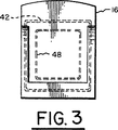
図3はEAS不活性化コイルとトランスポンダー呼び掛けアンテナの一つの実施例を示すダイヤグラムである。
図4は本発明の代替的な実施例を示す。
図5は本発明に使用する一体的タグの好ましい実施例を説明している。
好ましい実施例の詳細な説明
図1を参照すると、本発明の一つの実施例によるデータ収集及びEAS不活性化システムを組み込んでいる袋詰めステーション10が示されている。袋詰めステーション10はショッピングバッグ22又は他のばら荷コンテナを置くことがでる体積20を規定する、3個の側壁12、14、及び16と底部18を有する。或る量のショッピングバッグの手提げ部分をバッグラック26と28に掛け、ばら荷ホルダー24上に掛けることができ、ついで一度に一つ使用するために引き出す。ばら荷ホルダー24及びバッグラック26と28は側壁16に取り付けられている。ショッピングバッグ22は、当業界で周知のEASシステムと共に使用する関連するEASタグ32、及び高周波識別(RFID)チップとアンテナを有するトランスポンダー33を有する物品30、を含む。トランスポンダー33のRFIDチップはメモリを有する。このメモリは販売業務及び在庫制御の問題点を助ける他の情報と共に、物品及び物品の値付けを識別するデータを含むことができる。EASタグは登録商標「ULTRA・MAX」を付して本願の譲受人により販売されている磁気音響EASタグが好ましく、このようなEASタグは窃盗防止のため広く使用されている。
図2は袋詰めステーション10に使用する本発明の不活性化コイル及びトランスポンダーアンテナ構成を示す。不活性化コイル34は側壁12の内部に位置し不活性化コイル36は側壁14の内部に位置する。側壁12と側壁14は平行であり、したがって不活性化コイル34と不活性化コイル36は互いに平行面に位置する。不活性化コイル38は4個のコイル区分40、42、44、及び46を有する。コイル区分40は底部18の中のその前部近くに位置し、コイル区分42は側壁16の中のその頂部近くに位置する。コイル区分44とコイル区分46はそれぞれ側壁12と側壁14中に、不活性化コイル34と不活性化コイル36のそれぞれの対角線に概ね沿って位置する。電源から電圧をコイル34、36、及び38に印加して磁界を発生させEASタグ32を不活性化する。体積20のような所定の領域に位置するトランスポンダーに呼び掛けるアンテナ48がトランスポンダー33に含まれる物品30に関するデータを収集する。
図3は図1と図2に示されたシステムの側壁中のEAS不活性化コイル及びトランスポンダー呼び掛けアンテナの一つの実施例を図式的に説明している。不活性化コイル38のコイル区分42は図1及び図2において説明したように側壁16の頂部近くに位置する。図示のように呼び掛けコイル48は単一ループアンテナとするか、又は周知の代替的な構成のものを使用することができる。
図4は本発明の代替的な実施例を示し、EAS不活性化コイルとトランスポンダーコイルは登録商標「Rapid Pad」を付して本発明の譲受人により市販されている不活性化パッドのようなパッド、すなわちハウジング50中に位置する。EAS不活性化コイル52はハウジング50中に位置し、トランスポンダー呼び掛けアンテナ54もハウジング50中に位置する。図示のようにアンテナ54は不活性化コイル52の内側に位置するが、他の構成、例えばアンテナ54が不活性化コイル52の外側に位置するか、或いはアンテナ54と不活性化コイル52が重なるように位置する構成も可能である。周知のように不活性化コイル52はEAS不活性化システム56により作動する。アンテナ54は周知のようにトランスポンダー呼び掛けシステム58に接続されており、このシステム58は適切な呼び掛け信号をハウジング50の上の領域のような所定の領域に位置するトランスポンダーに提供し、勘定支払い中の物品に関する情報を収集しこの情報はその販売点における業務のために使用される。さらにトランスポンダー呼び掛けシステム58はトランスポンダーに情報を提供するか情報に書き込むことができる。この情報は販売日、販売地域、販売価格、及び物品の出所確認のための製造業者を含むことができる。この情報は表示装置60に表示される。表示装置60はモニター、キャッシュレジスター、又は他の適当な表示装置でもよい。さらにトランスポンダー呼び掛けシステム58はかかる情報を在庫制御又は他の用途のために記憶することができる。
図5を参照すると、本発明に使用する多機能タグ10の好ましい実施例が示されている。基体又はフイルムのような底部カバー12は上部表面14を有し、上部表面14の上にEASタグ16が位置している。RFIDチップ20とこのRFIDチップ20に接続されたアンテナ22を含むトランスポンダー18は、アンテナ22がEASタグ16の周囲に位置するよう上部表面14上に位置している。RFIDチップ20は周知のように論理とメモリを含み、このメモリはそれが付着される物品に関するデータを含むことができる。このデータは物品の識別、物品の値付け、及び在庫制御の情報を含むことができる。フイルム又はマイラーのようなカバー24はEASタグ16とトランスポンダー18をカバーする。上部表面14、EASタグ16、及びトランスポンダー18に接触するこのカバー24はこれら部品の一体の結合を助けるために接着剤を有することができる。底部カバー12は、トランスポンダー18を収容する大きさの空洞、及びEASタグ16を収容する大きさの他の空洞、を有するハウジングを含むことができる。
本発明の各種の改変と修正が本発明の範囲を逸脱することなくなし得ることを理解すべきである。又、本発明の範囲はここに開示した特定の実施例に限定解釈されるものでなく、請求の範囲の記載を上述の開示に照らして解釈されるべきであることを理解すべきである。 FIELD OF THE INVENTION The present invention relates to electronic article surveillance, and more particularly to data communications and deactivation of electronic article surveillance tags.
Background of the invention Electronic article surveillance (EAS) systems are used for reusable or disposable EAS tags on surveillance articles to prevent shoplifting and unauthorized movement of items from the store. The reusable EAS tag is usually removed from the item before the customer leaves the store. Disposable EAS tags are typically attached to or placed in a package with an adhesive. These tags remain in the article and must be deactivated before moving from the store by the customer. The deactivation device uses a coil that generates a magnetic field large enough to deactivate the EAS tag when a voltage is applied. The deactivated tag no longer responds to the EAS system projection energy and no alarm is triggered.
In one type of deactivation system, the checker passes items one over the deactivation device at a time to deactivate the tag, and then places the items in a shopping bag or bulk container. This system uses a single coil disposed horizontally in the housing. The checker moves the article with the tag on the horizontal top surface of the housing so that the tag is substantially flush with the coil.
Another deactivation system uses a housing that includes a cavity with three sets of two coils each disposed in the x, y, and z axis planes, respectively. Here, one coil is located in a parallel plane on each side of the cavity, and two coils are located one near the top of the cavity and the other near the bottom of the cavity.
The checker places the shopping bag or bulk container in the cavity, and then places the tagged item in the bag. After all the items have been placed in the bag or when the bag is full, the checker electrically applies the coil to deactivate the EAS tag in the bag. The accountant then pulls the bag out of the cavity. This system deactivates multiple tags at once and does not require a specific orientation of the tags.
Many retailers with large volumes view it desirable to facilitate and facilitate the billing process, including the collection of data regarding items being purchased and EAS tag deactivation. The data many retailers are looking for is product identification, product price, and other information for inventory control. In current applications, barcode labels are limited to the amount of data that can be provided, and the checker feels it is difficult to get the correct positional relationship between the barcode label and the barcode scanner, delaying the billing work. Yes.
SUMMARY OF THE INVENTION In accordance with the present invention, an apparatus for deactivating data communication and electronic article surveillance tags is provided. The apparatus includes an antenna for communicating with a transponder located in a predetermined area, and an inactivation coil for inactivating an electronic article surveillance tag located in the predetermined area.
The system of the present invention includes information gathering of sales operations issues to provide a complete solution that facilitates EAS deactivation and retail accounting. Radio frequency identification (RFID) tags are easily shielded or detuned by access to various materials and human bodies, and RFID tags with small coil shapes cannot provide the wide EAS coverage required by retailers. However, RFID tags are suitable for providing data regarding the item to which they are attached and are well suited for the rapid collection of data at point of sale. In addition, the data can be written to an RFID tag that can include the date of sale, the sales region, the sales price, and the manufacturer for confirmation of the origin of the item. The EAS tag provides the safety required by the retail environment.
Other objects, advantages and applications will become apparent from the following detailed description of preferred embodiments of the invention.
DESCRIPTION OF THE FIGURES FIG. 1 is a perspective view of a bagging station having a data collection and tag deactivation system according to one embodiment of the present invention.
FIG. 2 is a perspective view including a partial cutaway showing one embodiment of the deactivation coil and transponder interrogation antenna in the bagging station of FIG.
FIG. 3 is a diagram showing one embodiment of an EAS deactivating coil and a transponder interrogation antenna.
FIG. 4 shows an alternative embodiment of the present invention.
FIG. 5 illustrates a preferred embodiment of the integral tag used in the present invention.
Detailed Description of the Preferred Embodiment Referring to Figure 1, a
FIG. 2 shows the deactivation coil and transponder antenna configuration of the present invention for use in the
FIG. 3 schematically illustrates one embodiment of an EAS deactivation coil and transponder interrogation antenna in the sidewall of the system shown in FIGS. The
FIG. 4 shows an alternative embodiment of the present invention, in which the EAS deactivation coil and transponder coil are labeled as “Rapid Pad”, such as the deactivation pad marketed by the assignee of the present invention. Located in the pad or
Referring to FIG. 5, a preferred embodiment of a
It should be understood that various changes and modifications of the present invention can be made without departing from the scope of the invention. It should also be understood that the scope of the present invention should not be construed as limited to the particular embodiments disclosed herein, but that the claims should be construed in light of the above disclosure.
Claims (20)
前記物品を入れたバッグを置くことのできる領域を区画するハウジングであって該ハウジングは前記バッグを取り除くため開放された側面と開放された上面とを有するハウジングと、
前記物品が前記領域内にあるとき前記電子物品監視タグを同時に不活性化するため前記ハウジング内に設けられた複数の不活性化コイルと、
前記物品が前記領域内にあるとき前記データトランスポンダーと通信するため前記ハウジングに設けたアンテナを有するデータ通信システムと、
を具備することを特徴とする装置。An apparatus for use with an article having an associated data transponder and an associated electronic article surveillance tag comprising :
A housing defining an area in which a bag containing the article can be placed, the housing having an open side surface and an open top surface for removing the bag ;
A plurality of deactivation coils provided in the housing for simultaneously deactivating the electronic article surveillance tag when the article is in the region ;
A data communication system having an antenna provided in the housing for communicating with the data transponder when the article is in the area ;
The apparatus characterized by comprising.
Applications Claiming Priority (3)
| Application Number | Priority Date | Filing Date | Title |
|---|---|---|---|
| US08/721,175 US5990794A (en) | 1996-09-26 | 1996-09-26 | Apparatus for data communication and deactivation of electronic article surveillance tags |
| US08/721,175 | 1996-09-26 | ||
| PCT/US1997/017570 WO1998013805A1 (en) | 1996-09-26 | 1997-09-26 | An apparatus for data communication and deactivation of electronic article surveillance tags |
Publications (2)
| Publication Number | Publication Date |
|---|---|
| JP2001503890A JP2001503890A (en) | 2001-03-21 |
| JP3876000B2 true JP3876000B2 (en) | 2007-01-31 |
Family
ID=24896860
Family Applications (1)
| Application Number | Title | Priority Date | Filing Date |
|---|---|---|---|
| JP51600298A Expired - Fee Related JP3876000B2 (en) | 1996-09-26 | 1997-09-26 | Deactivation of data communication and electronic article monitoring tags |
Country Status (10)
| Country | Link |
|---|---|
| US (1) | US5990794A (en) |
| EP (1) | EP0928472B1 (en) |
| JP (1) | JP3876000B2 (en) |
| AR (1) | AR010483A1 (en) |
| AU (1) | AU729012B2 (en) |
| BR (1) | BR9713228A (en) |
| CA (1) | CA2265819C (en) |
| DE (1) | DE69735193T2 (en) |
| HK (1) | HK1023436A1 (en) |
| WO (1) | WO1998013805A1 (en) |
Families Citing this family (62)
| Publication number | Priority date | Publication date | Assignee | Title |
|---|---|---|---|---|
| US5963134A (en) * | 1997-07-24 | 1999-10-05 | Checkpoint Systems, Inc. | Inventory system using articles with RFID tags |
| DE19740871A1 (en) * | 1997-09-16 | 1999-06-17 | Meto International Gmbh | Method and device for recognizing and deactivating a deactivatable security element |
| AU2003204065B2 (en) * | 1998-08-14 | 2006-04-13 | 3M Innovative Properties Company | Applications for radio frequency identification systems |
| ATE376232T1 (en) * | 1998-08-14 | 2007-11-15 | 3M Innovative Properties Co | APPLICATIONS FOR RADIO FREQUENCY IDENTIFICATION SYSTEMS |
| US6424262B2 (en) * | 1998-08-14 | 2002-07-23 | 3M Innovative Properties Company | Applications for radio frequency identification systems |
| US6176425B1 (en) * | 1998-09-10 | 2001-01-23 | Xerox Corporation | Information management system supporting multiple electronic tags |
| US6924781B1 (en) | 1998-09-11 | 2005-08-02 | Visible Tech-Knowledgy, Inc. | Smart electronic label employing electronic ink |
| US6753830B2 (en) | 1998-09-11 | 2004-06-22 | Visible Tech-Knowledgy, Inc. | Smart electronic label employing electronic ink |
| US6517000B1 (en) | 1999-05-03 | 2003-02-11 | Psc Scanning, Inc. | Dual ended cable for connecting electronic article surveillance antenna with RFID equipment |
| US6598790B1 (en) * | 1999-06-22 | 2003-07-29 | Douglas B. Horst | Self-service checkout |
| DK1236171T3 (en) | 1999-12-07 | 2004-08-09 | Datamars Sa | Method of operating a transponder |
| US6486782B1 (en) | 2000-07-07 | 2002-11-26 | 3M Innovative Properties | Device for changing the status of dual status magnetic electronic article surveillance markers |
| US6646555B1 (en) | 2000-07-18 | 2003-11-11 | Marconi Communications Inc. | Wireless communication device attachment and detachment device and method |
| US20020183882A1 (en) | 2000-10-20 | 2002-12-05 | Michael Dearing | RF point of sale and delivery method and system using communication with remote computer and having features to read a large number of RF tags |
| USRE47599E1 (en) | 2000-10-20 | 2019-09-10 | Promega Corporation | RF point of sale and delivery method and system using communication with remote computer and having features to read a large number of RF tags |
| AU1176902A (en) | 2000-10-20 | 2002-05-06 | Promega Corp | Radio frequency identification method and system of distributing products |
| KR20030011069A (en) * | 2000-12-15 | 2003-02-06 | 이스턴 리본 앤 롤 콥. | Paper roll anti-theft protection |
| US6595421B2 (en) | 2001-01-31 | 2003-07-22 | Ncr Corporation | Integrated antenna scanner window |
| US6547040B2 (en) * | 2001-04-02 | 2003-04-15 | Ncr Corporation | Self-service checkout system with RFID capability |
| US6507279B2 (en) | 2001-06-06 | 2003-01-14 | Sensormatic Electronics Corporation | Complete integrated self-checkout system and method |
| US6778087B2 (en) | 2001-06-15 | 2004-08-17 | 3M Innovative Properties Company | Dual axis magnetic field EAS device |
| US8321302B2 (en) | 2002-01-23 | 2012-11-27 | Sensormatic Electronics, LLC | Inventory management system |
| US8339265B2 (en) | 2002-01-09 | 2012-12-25 | Sensormatic Electronics, Llc. | Method of assigning and deducing the location of articles detected by multiple RFID antennae |
| US6783072B2 (en) * | 2002-02-01 | 2004-08-31 | Psc Scanning, Inc. | Combined data reader and electronic article surveillance (EAS) system |
| WO2003067538A2 (en) * | 2002-02-01 | 2003-08-14 | Psc Scanning, Inc. | Systems and methods for data reading and eas tag sensing and deactivating at retail checkout |
| US6854647B2 (en) * | 2002-02-01 | 2005-02-15 | Ncr Corporation | Checkout device including integrated barcode reader, scale, and EAS system |
| US6619546B1 (en) * | 2002-03-14 | 2003-09-16 | Wal-Mart Stores, Inc. | Systems and methods for pre-scanning merchandise in customer's shopping cart while customer is waiting in checkout line |
| US7527198B2 (en) | 2002-03-18 | 2009-05-05 | Datalogic Scanning, Inc. | Operation monitoring and enhanced host communications in systems employing electronic article surveillance and RFID tags |
| US6752837B2 (en) | 2002-06-28 | 2004-06-22 | Hewlett-Packard Development Company, L.P. | Security tags with a reversible optical indicator |
| US6894232B2 (en) * | 2002-08-12 | 2005-05-17 | Mettler-Toledo | Bagger scale |
| US6809645B1 (en) * | 2002-08-30 | 2004-10-26 | Ncr Corporation | System and method for updating a product database based on surveillance tag detection at a self-checkout station |
| US20040103034A1 (en) * | 2002-11-21 | 2004-05-27 | Kimberly-Clark Worldwide, Inc. | RFID system and method for purchase item accountability |
| US7617132B2 (en) * | 2002-11-21 | 2009-11-10 | Kimberly-Clark Worldwide, Inc. | RFID system and method for ensuring food safety |
| US7490054B2 (en) * | 2002-11-21 | 2009-02-10 | Kimberly-Clark Worldwide, Inc. | RFID system and method for vending machine control |
| US6853303B2 (en) | 2002-11-21 | 2005-02-08 | Kimberly-Clark Worldwide, Inc. | RFID system and method for ensuring personnel safety |
| US6982640B2 (en) * | 2002-11-21 | 2006-01-03 | Kimberly-Clark Worldwide, Inc. | RFID system and method for tracking food freshness |
| US7061379B2 (en) * | 2002-11-21 | 2006-06-13 | Kimberly-Clark Worldwide, Inc. | RFID system and method for ensuring safety of hazardous or dangerous substances |
| US7119664B2 (en) * | 2003-09-17 | 2006-10-10 | Id Solutions, Inc. | Deep sleep in an RFID tag |
| US7853477B2 (en) * | 2003-12-30 | 2010-12-14 | O'shea Michael D | RF-based electronic system and method for automatic cross-marketing promotional offers and check-outs |
| US7463142B2 (en) | 2003-12-30 | 2008-12-09 | Kimberly-Clark Worldwide, Inc. | RFID system and method for tracking environmental data |
| US20050149414A1 (en) * | 2003-12-30 | 2005-07-07 | Kimberly-Clark Worldwide, Inc. | RFID system and method for managing out-of-stock items |
| US20050200485A1 (en) * | 2004-02-09 | 2005-09-15 | One World Technologies Limited | Article containing anti-theft device |
| US7336183B2 (en) * | 2004-04-30 | 2008-02-26 | Kimberly-Clark Worldwide, Inc. | Decommissioning an electronic data tag |
| US7151455B2 (en) * | 2004-04-30 | 2006-12-19 | Kimberly-Clark Worldwide, Inc. | Activating a data tag by load or orientation or user control |
| US7098794B2 (en) * | 2004-04-30 | 2006-08-29 | Kimberly-Clark Worldwide, Inc. | Deactivating a data tag for user privacy or tamper-evident packaging |
| US7948381B2 (en) | 2004-04-30 | 2011-05-24 | Binforma Group Limited Liability Company | Reversibly deactivating a radio frequency identification data tag |
| US7068172B2 (en) * | 2004-05-21 | 2006-06-27 | Xiao Hui Yang | Method and apparatus for deactivating an EAS device |
| EP1776109B1 (en) * | 2004-08-13 | 2008-12-31 | Schering-Plough Ltd. | Pharmaceutical formulation comprising an antibiotic, a triazole and a corticosteroid |
| US7109867B2 (en) * | 2004-09-09 | 2006-09-19 | Avery Dennison Corporation | RFID tags with EAS deactivation ability |
| US7207488B2 (en) * | 2004-11-04 | 2007-04-24 | Precision Dynamics Corproation | Combined barcode scanner and radio frequency identification reader with field interpretation array |
| US7619527B2 (en) | 2005-02-08 | 2009-11-17 | Datalogic Scanning, Inc. | Integrated data reader and electronic article surveillance (EAS) system |
| US7304574B2 (en) * | 2005-02-10 | 2007-12-04 | Sensormatic Electronics Corporation | Alarm investigation using RFID |
| US20070214021A1 (en) * | 2006-03-07 | 2007-09-13 | International Business Machines Corporation | Automated service offering and loss recovery system |
| DE102006043786A1 (en) * | 2006-09-13 | 2008-03-27 | Fraunhofer-Gesellschaft zur Förderung der angewandten Forschung e.V. | Container and device for detecting objects located in an interior of the container |
| US7710275B2 (en) | 2007-03-16 | 2010-05-04 | Promega Corporation | RFID reader enclosure and man-o-war RFID reader system |
| US7986241B2 (en) * | 2008-01-25 | 2011-07-26 | Sensomatic Electronics, LLC | Combination security tag using a perimeter RFID antenna surrounding an EAS element and method thereof |
| US20090212952A1 (en) * | 2008-02-22 | 2009-08-27 | Xiao Hui Yang | Method and apparatus for de-activating eas markers |
| BRPI0823043A2 (en) | 2008-09-26 | 2015-07-28 | Thomson Licensing | Signal Transmission Control Method for Multiple Devices |
| JP6134262B2 (en) * | 2013-12-27 | 2017-05-24 | 東芝テック株式会社 | Product information input device, system and program |
| US9978235B2 (en) * | 2015-07-02 | 2018-05-22 | Tyco Fire & Security Gmbh | Multi-technology transponder and system |
| DE102019211607B4 (en) | 2019-08-01 | 2024-03-14 | Vega Grieshaber Kg | Measuring device with near-field antenna |
| US11661327B2 (en) | 2020-12-16 | 2023-05-30 | Fresh Blends Ltd. | Smart inventory management system for a dispensing and blend-in-cup beverage platform |
Family Cites Families (15)
| Publication number | Priority date | Publication date | Assignee | Title |
|---|---|---|---|---|
| US4084742A (en) * | 1976-08-02 | 1978-04-18 | Silverman Richard H | Price marking system for automated check-out of merchandize |
| US4413254A (en) * | 1981-09-04 | 1983-11-01 | Sensormatic Electronics Corporation | Combined radio and magnetic energy responsive surveillance marker and system |
| US4829397A (en) * | 1985-02-28 | 1989-05-09 | Odesskoe Spetsialnoe Konstruktorskoe Bjuro Spetsialnykh Stankov | Apparatus for demagnetizing parts |
| US5005125A (en) * | 1986-02-28 | 1991-04-02 | Sensormatic Electronics Corporation | Surveillance, pricing and inventory system |
| US5258766A (en) * | 1987-12-10 | 1993-11-02 | Uniscan Ltd. | Antenna structure for providing a uniform field |
| US5059951A (en) * | 1988-11-14 | 1991-10-22 | Checkpoint Systems, Inc. | Method and apparatus for integrated data capture and electronic article surveillance |
| DE4015779A1 (en) * | 1990-05-16 | 1991-11-21 | Minnesota Mining & Mfg | Electro magnetic desensitiser appts. |
| GB9202831D0 (en) * | 1992-02-11 | 1992-03-25 | Shanning Laser Systems Ltd | Security tag |
| US5260690A (en) * | 1992-07-02 | 1993-11-09 | Minnesota Mining And Manufacturing Company | Article removal control system |
| US5410296A (en) * | 1992-10-06 | 1995-04-25 | Minnesota Mining And Manufacturing Company | Magnetic tag deactivator for pre-existing check-out counters |
| CH684661A5 (en) * | 1992-12-11 | 1994-11-15 | Kobe Properties Ltd | Method and device for protection against theft of articles. |
| WO1995012870A1 (en) * | 1993-11-04 | 1995-05-11 | Knogo Corporation | Method and apparatus for automatically desensitizing sensor elements |
| US5469142A (en) * | 1994-08-10 | 1995-11-21 | Sensormatic Electronics Corporation | Electronic article surveillance system having enhanced tag deactivation capacity |
| CA2148749A1 (en) * | 1994-08-30 | 1996-03-01 | Joerg W. Zschirnt | Apparatus for deactivation of electronic article surveillance tags |
| US5705986A (en) * | 1996-09-26 | 1998-01-06 | Sensormatic Electronic Corporation | Method of and apparatus for automatic deactivation of electronic article surveillance tags |
-
1996
- 1996-09-26 US US08/721,175 patent/US5990794A/en not_active Expired - Lifetime
-
1997
- 1997-09-25 AR ARP970104416A patent/AR010483A1/en unknown
- 1997-09-26 WO PCT/US1997/017570 patent/WO1998013805A1/en active IP Right Grant
- 1997-09-26 CA CA002265819A patent/CA2265819C/en not_active Expired - Fee Related
- 1997-09-26 JP JP51600298A patent/JP3876000B2/en not_active Expired - Fee Related
- 1997-09-26 EP EP97909902A patent/EP0928472B1/en not_active Expired - Lifetime
- 1997-09-26 BR BR9713228-4A patent/BR9713228A/en not_active IP Right Cessation
- 1997-09-26 DE DE69735193T patent/DE69735193T2/en not_active Expired - Fee Related
- 1997-09-26 AU AU47407/97A patent/AU729012B2/en not_active Ceased
-
2000
- 2000-01-14 HK HK00100262A patent/HK1023436A1/en not_active IP Right Cessation
Also Published As
| Publication number | Publication date |
|---|---|
| WO1998013805A1 (en) | 1998-04-02 |
| BR9713228A (en) | 2000-04-04 |
| US5990794A (en) | 1999-11-23 |
| AR010483A1 (en) | 2000-06-28 |
| EP0928472A4 (en) | 2002-04-10 |
| AU4740797A (en) | 1998-04-17 |
| CA2265819A1 (en) | 1998-04-02 |
| DE69735193T2 (en) | 2006-11-02 |
| CA2265819C (en) | 2004-11-30 |
| EP0928472B1 (en) | 2006-02-01 |
| EP0928472A1 (en) | 1999-07-14 |
| HK1023436A1 (en) | 2000-09-08 |
| AU729012B2 (en) | 2001-01-25 |
| DE69735193D1 (en) | 2006-04-13 |
| JP2001503890A (en) | 2001-03-21 |
Similar Documents
| Publication | Publication Date | Title |
|---|---|---|
| JP3876000B2 (en) | Deactivation of data communication and electronic article monitoring tags | |
| JP4151916B2 (en) | Data communication and electronic article monitoring tags | |
| WO1998013804A9 (en) | A data communication and electronic article surveillance tag | |
| US6154135A (en) | Apparatus for capturing data and deactivating electronic article surveillance tags | |
| US8079132B2 (en) | Method for shielding RFID tagged discarded items in retail, manufacturing and wholesale industries | |
| US7859410B2 (en) | Universal tracking assembly | |
| JPH10124764A (en) | Electronic shoplifting prevention system using rfid tag | |
| US8081078B2 (en) | Universal tracking assembly | |
| WO2012094753A1 (en) | Rfid security tag based monitoring system and detachers for use therewith | |
| US8174387B2 (en) | Method of shipping and tracking inventory | |
| JP3221876B2 (en) | Method of tagging goods for use with electronic goods monitoring systems, and tags or labels used therefor | |
| JP2018120368A (en) | Bagging system, and shopping support system therewith | |
| JP4521969B2 (en) | Product sales confirmation method and price tag | |
| JP2004240767A (en) | Antishoplifting system | |
| EP1103473A1 (en) | Paper/paperboard cartons or containers having printed security code | |
| EP0712521A1 (en) | Improvements in labelling |
Legal Events
| Date | Code | Title | Description |
|---|---|---|---|
| A621 | Written request for application examination |
Free format text: JAPANESE INTERMEDIATE CODE: A621 Effective date: 20040903 |
|
| A131 | Notification of reasons for refusal |
Free format text: JAPANESE INTERMEDIATE CODE: A131 Effective date: 20050802 |
|
| A601 | Written request for extension of time |
Free format text: JAPANESE INTERMEDIATE CODE: A601 Effective date: 20051101 |
|
| A602 | Written permission of extension of time |
Free format text: JAPANESE INTERMEDIATE CODE: A602 Effective date: 20051219 |
|
| A521 | Request for written amendment filed |
Free format text: JAPANESE INTERMEDIATE CODE: A523 Effective date: 20060201 |
|
| TRDD | Decision of grant or rejection written | ||
| A01 | Written decision to grant a patent or to grant a registration (utility model) |
Free format text: JAPANESE INTERMEDIATE CODE: A01 Effective date: 20061003 |
|
| A61 | First payment of annual fees (during grant procedure) |
Free format text: JAPANESE INTERMEDIATE CODE: A61 Effective date: 20061030 |
|
| R150 | Certificate of patent or registration of utility model |
Free format text: JAPANESE INTERMEDIATE CODE: R150 |
|
| FPAY | Renewal fee payment (event date is renewal date of database) |
Free format text: PAYMENT UNTIL: 20091102 Year of fee payment: 3 |
|
| FPAY | Renewal fee payment (event date is renewal date of database) |
Free format text: PAYMENT UNTIL: 20101102 Year of fee payment: 4 |
|
| FPAY | Renewal fee payment (event date is renewal date of database) |
Free format text: PAYMENT UNTIL: 20111102 Year of fee payment: 5 |
|
| FPAY | Renewal fee payment (event date is renewal date of database) |
Free format text: PAYMENT UNTIL: 20121102 Year of fee payment: 6 |
|
| FPAY | Renewal fee payment (event date is renewal date of database) |
Free format text: PAYMENT UNTIL: 20121102 Year of fee payment: 6 |
|
| FPAY | Renewal fee payment (event date is renewal date of database) |
Free format text: PAYMENT UNTIL: 20131102 Year of fee payment: 7 |
|
| S111 | Request for change of ownership or part of ownership |
Free format text: JAPANESE INTERMEDIATE CODE: R313111 |
|
| S531 | Written request for registration of change of domicile |
Free format text: JAPANESE INTERMEDIATE CODE: R313531 |
|
| R350 | Written notification of registration of transfer |
Free format text: JAPANESE INTERMEDIATE CODE: R350 |
|
| S111 | Request for change of ownership or part of ownership |
Free format text: JAPANESE INTERMEDIATE CODE: R313113 Free format text: JAPANESE INTERMEDIATE CODE: R313111 |
|
| R360 | Written notification for declining of transfer of rights |
Free format text: JAPANESE INTERMEDIATE CODE: R360 |
|
| R360 | Written notification for declining of transfer of rights |
Free format text: JAPANESE INTERMEDIATE CODE: R360 |
|
| R371 | Transfer withdrawn |
Free format text: JAPANESE INTERMEDIATE CODE: R371 |
|
| S111 | Request for change of ownership or part of ownership |
Free format text: JAPANESE INTERMEDIATE CODE: R313113 Free format text: JAPANESE INTERMEDIATE CODE: R313111 |
|
| R350 | Written notification of registration of transfer |
Free format text: JAPANESE INTERMEDIATE CODE: R350 |
|
| LAPS | Cancellation because of no payment of annual fees |