JP3875650B2 - Support structure of mouse shutter in full face helmet - Google Patents
Support structure of mouse shutter in full face helmet Download PDFInfo
- Publication number
- JP3875650B2 JP3875650B2 JP2003130955A JP2003130955A JP3875650B2 JP 3875650 B2 JP3875650 B2 JP 3875650B2 JP 2003130955 A JP2003130955 A JP 2003130955A JP 2003130955 A JP2003130955 A JP 2003130955A JP 3875650 B2 JP3875650 B2 JP 3875650B2
- Authority
- JP
- Japan
- Prior art keywords
- fitting portion
- guide shaft
- fitting
- shutter
- mouse shutter
- Prior art date
- Legal status (The legal status is an assumption and is not a legal conclusion. Google has not performed a legal analysis and makes no representation as to the accuracy of the status listed.)
- Expired - Fee Related
Links
Images


Classifications
-
- A—HUMAN NECESSITIES
- A42—HEADWEAR
- A42B—HATS; HEAD COVERINGS
- A42B3/00—Helmets; Helmet covers ; Other protective head coverings
- A42B3/04—Parts, details or accessories of helmets
- A42B3/18—Face protection devices
- A42B3/22—Visors
-
- A—HUMAN NECESSITIES
- A42—HEADWEAR
- A42B—HATS; HEAD COVERINGS
- A42B3/00—Helmets; Helmet covers ; Other protective head coverings
- A42B3/04—Parts, details or accessories of helmets
- A42B3/18—Face protection devices
- A42B3/22—Visors
- A42B3/221—Attaching visors to helmet shells, e.g. on motorcycle helmets
- A42B3/222—Attaching visors to helmet shells, e.g. on motorcycle helmets in an articulated manner, e.g. hinge devices
-
- A—HUMAN NECESSITIES
- A42—HEADWEAR
- A42B—HATS; HEAD COVERINGS
- A42B3/00—Helmets; Helmet covers ; Other protective head coverings
- A42B3/04—Parts, details or accessories of helmets
- A42B3/28—Ventilating arrangements
- A42B3/281—Air ducting systems
- A42B3/283—Air inlets or outlets, with or without closure shutters
Abstract
Description
【0001】
【発明の属する技術分野】
本発明は、フルフェースヘルメットのマウスシャッタの支持構造に関する。
【0002】
【従来技術】
ヘルメットにおける回動開閉体は、フルフェースヘルメットであればヘルメット内にこもる熱気を換気する換気孔を開閉するマウスシャッタであり、フルフェースヘルメットとジェット型ヘルメットの場合には、着用者の顔面を保護するシールドである。
通常の回動開閉体の支持構造は、その回動における回動中心を単一として支持されて、その開閉動作の回動軌跡が一定の弧を描くように開閉するようになっているが、この支持構造であると、ヘルメットの設計自由度が狭くなるということがあった。
そのため、本出願人は、前記回動開閉体であるシールドの支持構造として、2箇所の分離した円弧孔を開設し、それら円弧孔それぞれにシールドの回動中心を2箇所ずつ設け、シールドの開閉動作中に回動中心が順次切換るようにした構造を提案している。(特許文献1参照)
【0003】
【特許文献1】
特許第2878262号公報(〔0010〕〜〔0013〕、〔図1〕、〔図3〕、〔図4〕)
【0004】
ところで、シールドの曇りや熱気のこもりを迅速に取り除くには、外気の導入量を増やしてヘルメット内の換気効率を高める必要が有り、その手段の一つとして換気孔を大きく形成することにより外気の導入量を増やすことが考えられる。
しかしながら、マウスシャッタの大きさは換気孔の大きさに対応するため、マウスシャッタが前記回動中心を単一とする支持形態であると、例えば、図12および図13に示すように、マウスシャッタ102の支持位置によっては、マウスシャッタ開状態においてマウスシャッタ102が顎ガード部101表面から外側に大きく突出してヘルメットのデザインを損ねる可能性がある。
そのため、マウスシャッタの全開状態における角度を小さくして突出量を少なくすることが挙げられるが、これでは、換気孔を大きくしても外気の導入量を増やすことはできない。
逆に、マウスシャッタをヘルメット内側方向へ開閉させる方法も考えられるが、この方法では、マウスシャッタがヘルメット内側に大きく突出するため、顎ガード部の内側にマウスシャッタのスペースを確保する必要もあるし、開閉における操作性という点で現実的には採用できない。
つまり、外気の導入量の増加とデザイン性および操作性を満足させるということを実現するマウスシャッタの回動中心の設定を行うことが難しく、このことが、ヘルメットの設計の自由度を狭くさせる要因となっている。
【0005】
そこで、本願出願人は、前記先行技術文献に記載の支持構造を、前記した構成をマウスシャッタの開閉に採用することによって、ヘルメットの設計の自由度の拡大、ヘルメットのデザイン性の確保、ヘルメット内の換気効率および操作性の向上等を図った。
しかしながら、マウスシャッタはシールドに比べて極めて小さいものであるため、前記先行技術文献に記載の支持構造を、マウスシャッタの支持構造として採用するには、その構造を構成するに必要なスペースが確保できず、現実的には極めて難しいものである。
【0006】
【発明が解決しようとする課題】
そこで本発明は、外気の導入量の増加、デザイン性および操作性の向上、ヘルメットの設計自由度の実現を課題とし、この課題を解決する新規なマウスシャッタの支持構造を提供することを目的とする。
【0007】
【課題を解決するための手段】
本発明は上記した目的を達成するために下記の技術的手段を採用する。
その技術的手段は、フルフェースヘルメットの顎ガードに設けられる換気孔開閉のマウスシャッタを、帽体側に固定されるマウスシャッタ支持部に対して回動可能に支持する支持構造であって、マウスシャッタ開閉における回動中心が少なくとも2箇所以上複数有り、マウスシャッタの閉状態から開状態への開動動作途中で前記の回動中心が切替わるようにしていることを特徴とする支持構造にしたことである。
【0008】
【発明の実施の形態】
前記支持構造を具体的に実施する構成として、例えば、図1〜図5に示すように、帽体側に固定されるマウスシャッタ支持部と、これに対して回動可能に支持されるマウスシャッタのいずれか一方には、回動を案内する第1案内軸(S1)と第2案内軸(S2)が、他方には前記による2つの案内軸に対応して複数の円弧形からなる嵌合部が備えられ、第1案内軸(S1)に対しては第1嵌合部(U1)とそれに連設される第2嵌合部(U2)が、第2案内軸(S2)に対しては第3嵌合部(U3)が夫々移動可能に嵌合して備えられ、マウスシャッタ開動作の当初においては、第1案内軸(S1)は第1嵌合部(U1)によって、第2案内軸(S2)は第3嵌合部(U3)によって夫々案内されることにより、両嵌合部の持つ円弧の共通の中心点である第1中心点(P1)を回動中心として回動し、開動作の途中、第1案内軸(S1)が第1嵌合部(U1)と第2嵌合部(U2)の連結点に到達した時点から、回動中心を第1中心点(P1)から第2嵌合部(U2)の持つ円弧の第2中心点(P2)に切替えて、第2案内軸(S2)を中心として回動するような構成とすることが挙げられる。(請求項1)
【0009】
本発明の支持構造によれば、図5(a)〜(c)の開動作においては第1中心点P1がマウスシャッタ1の回動中心であり、第1嵌合部U1と第3嵌合部U3が図5(c)の状態に至ると同時に、マウスシャッタ1の回動中心が第2中心点P2に切替り、図5(d)〜図5(e)の開動作となって、図5(e)および図4に示す全開状態において、顎ガード部A1の表面から外方へのマウスシャッタ1の突出量を最小限に抑えることができる。
【0010】
前記で例示した形態は、マウスシャッタ1の回動中心が2箇所とする形態であるが、本発明ではこれに限定されるものではなく、例えば、曲率が異なる円弧を含む嵌合部(図6)や、直線をある角度の曲部を介して連結して構成とする嵌合部(図7)のように、嵌合部の回動中途で回動中心が移動することで2箇所を超える回動中心となる形態も包含する。
【0011】
図示においては、マウスシャッタ1に各嵌合部を設け、各案内軸をシャッタ支持板2に設けてあるが、本発明はこの逆態様の支持構造も含む。
請求項2において、各嵌合部は、各案内軸が嵌合する形態であれば、孔形態または溝形態のいずれでもよい。
また、図8に示すように、第1案内軸(S1’)が移動可能に嵌合する第1嵌合部(U1’)および第2嵌合部(U2’)と、第2案内軸(S2’)が移動可能に嵌合する第3嵌合部(U3’)は溝形態であって、この溝形態とする第2嵌合部(U2’)と第3嵌合部(U3’)とには段差を設けて、両嵌合部の交差部においても夫々の軸を他の嵌合部に逸脱させないようにすることがより確実となる。(請求項2)
【0012】
【実施例】
以下、本発明の実施例を図面に基づいて説明する。
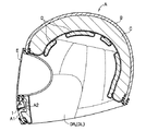
図1はフルフェースヘルメットAを示し、図3および図4に示すように顎ガード部A1にマウスシャッタ1で開閉される換気孔A2を備えている。
本実施例のフルフェースヘルメットAは、繊維強化樹脂材で所定の形状に形成された帽体Bの内側に、発泡スチロール、若しくは、これと同様の衝撃吸収性能を有する素材を用いて構成された衝撃吸収ライナーCと、その衝撃吸収ライナーCの内側に着脱可能に配設されるウレタン材等でなる頭部の内装パッドDと、頬部及び顎部に対応する両側部に配設された頬パッドDL,DRと、透明または有色透明、且つ、弾性を有する合成樹脂板を用いて所定形状に形成されたシールドEを備えて構成した周知形態のものである。
【0013】
マウスシャッタ1は、顎ガード部A1に取付けられたシャッタ支持部2に回動可能に支持され、その表面が全閉状態においてシャッタ支持部2の表面と面一としている。
マウスシャッタ支持部2は、マウスシャッタ1により開閉される換気孔3を備え、顎ガード部A1に開口された貫通口A3に固定され、その表面が顎ガード部A1の表面とほぼ面一としている。
マウスシャッタ1は、基本的にはシャッタ本体11の左右夫々に設けられた第1嵌合部U1と第2嵌合部U2に、マウスシャッタ支持部2の左右夫々に設けられた第1案内軸S1と第2案内軸S2が嵌合することにより、シャッタ支持板2に回動可能に支持される構成のものである。
【0014】
具体的には図2ないし図5に示すように、第1嵌合部U1と第2嵌合部U2は、シャッタ本体11の左右に一体形成された支持板1L,1Rに開孔され、第1案内軸S1と第2案内軸S2は、換気孔3における左右に前記支持板1L,1Rと対面するように一体形成された支持板3L,3Rに突出形成してあり、第1案内軸S1が第1嵌合部U1に、第2案内軸S2が第3嵌合部U3に夫々嵌合することでマウスシャッタ1がシャッタ支持板2に回動可能に支持される。
マウスシャッタ1は、第1中心点P1と第2中心点P2の2箇所の回動中心での回動により開閉動作するようにしてあり、図5に示すように、閉状態から開状態に至る回動途中で、回動中心が第1中心点P1から第2中心点P2に切替るようにしてある。
【0015】
以下、回動中心が切替わる構造を詳述すると、図5に示すように、第1嵌合部U1と第3嵌合部U3は、マウスシャッタ1の閉状態からの開動作において、最初は第1中心点P1を回動中心として、夫々径が異なる弧C1,C2を描き、マウスシャッタ1の開動作途中で回動中心を第1中心点P1から第2案内軸S2と同心とする第2中心点P2に切替え、さらに、第2嵌合部U2が切替え後の開動作において第2中心点P2を回動中心として弧C3を描く形状に形成してある。
第1嵌合部U1と第2嵌合部U2とは、第1中心点P1から第2中心点P2に切替る位置において連設されている。
中心点が切替る位置は、マウスシャッタ1の回動途中で第1嵌合部U1の屈曲部分U11が第1案内軸S1に接触して、第1中心点P1を回動中心とする回動が終了する位置であり、このとき、第3嵌合部U3の終端部U31が第2案内軸S2に接触する位置である。(図5(c)参照)
【0016】
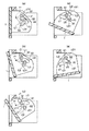
このようにした支持構造によるマウスシャッタ1の開閉動作を図5(a)〜(e)に基づいて説明する。
先ず、図5(a)に示すように、マウスシャッタ1の全閉状態においては、第1嵌合部U1の始端部U12が第1案内軸S1に接触し、第2案内軸S2が第2嵌合部U2と第3嵌合部U3の交わる部位(第3嵌合部U3の始端部U32)に位置している。
次に、全閉状態からマウスシャッタ1を開動作させると、図5(b)に示すように、マウスシャッタ1は第1中心点P1を回動中心として、第1嵌合部U1と第3嵌合部U3が第1案内軸S1と第2案内軸S2に案内されて回動する。
そして、さらに、マウスシャッタ1が回動すると、図5(c)に示す位置において、第1嵌合部U1の屈曲部分U11が第1案内軸S1に接触し、第3嵌合部U3の終端部U31が第2案内軸S2に接触することによって、回動中心が第1中心点P1から第2中心点P2に切替えられる。
この位置からマウスシャッタ1を開動作させると、図5(d)に示すように、マウスシャッタ1は第2中心点P2を回動中心として、第2嵌合部U2が第1案内軸S1に案内されて回動する。
そして、全開状態では、図5(e)に示すように、第2嵌合部U2の終端部U21が第1案内軸S1に接触してマウスシャッタ1の回動が停止する。
【0017】
本実施例の支持構造によれば、全開状態において、マウスシャッタ1の前端部をシャッタ支持部2の表面から外方へさほど突出させず、しかも、換気孔3の全域を開孔することができる。
【0018】
図6および図7は、マウスシャッタ1における回動中心を2箇所を超す数とした例を夫々示している。
なお、図6における各嵌合部は、第1嵌合部U10、第2嵌合部U20、第3嵌合部U30とし、図7における各嵌合部は、第1嵌合部U10'、第2嵌合部U20'、第3嵌合部U30'とする。
【0019】
図6における第1嵌合部U10および第3嵌合部U30の形態は、嵌合部における円弧の曲率が中途部分から変化する形態のものであり、この異なる曲率の円弧に沿う回動の各々の回動中心点を有している。
具体的には、始端部から回動中途までの円弧C4,C40よりも、当該回動中途から終端部までの円弧C5,C50の径を大きくしたものであり、そのため、円弧C4,C40の回動中心である第1中心点P3の位置と円弧C5,C50の回動中心である第2中心点P4が異なる位置となる。
つまり、円弧C4,C40における回動の中心は第1中心点P3であり、この回動中途から連続して円弧C5,C50に沿う回動に切り替わるとき、その回動の中心が第1中心点P3から第2中心点P4の間で徐々に移動して、当該第2中心点P4に切り替わる。
この場合、回動の中心が第1中心点P3から第2中心点P4に移動する状態においても円弧C5,C50に沿う回動があるため、第1中心点P3から第2中心点P4の間にも複数の中心点が存在する。
そして、第2中心点P4を回動中心とする円弧C5,C50に沿う回動が終了すると同時に、第3中心点P5を回動中心とする円弧C6に沿う回動が開始される。
したがって、前記実施例におけるマウスシャッタの回動中心の数は、第1、第2、第3中心点の3箇所と、第1中心点P3から第2中心点P4の間に存在する複数の中心点であり、このような3箇所以上の複数の回動中心が存在する構成においても実施が可能である。
【0020】
図7における第1嵌合部U10'、第2嵌合部U20'、第3嵌合部U30'の形態は、複数の直線ST1〜ST9を各形状の曲部を介して連結して構成した形態である。
この構成は、マウスシャッタの回動運動において、各案内軸が曲部に接触する度に回動運動が規制されるようにしたものであり、この規制により、マウスシャッタの開操作にラチェット機能が発揮される。
また、この構成においては、マウスシャッタは各直線に沿って移動するため、厳密には回動運動ではないが、マウスシャッタの全体的な動作を見たときにおいては回動運動に近い動作を行う。
つまり、各直線に沿って移動しようとしながら回動しようとする動作となるため、その動作中にずれが生じるが、大きくは回動の中心点P6および中心点P7を回動中心とする動作とみなすことができる。
したがって、本実施例の形態も2箇所を超す複数の回動の中心点が存在するものである。
【0021】
前記実施例における第1嵌合部U1と第2嵌合部U2は貫通孔として説明したが、本発明では図8に示す溝形態にすることも任意である。
以下、本実施例の溝形態とする第1嵌合部と第2嵌合部の形態を説明するが、本実施例の第1嵌合部には符号U1’を、第2嵌合部には符号U2’を、第3嵌合部には符号U3’を夫々付す。
また、第1案内軸には符号S1’を、第2案内軸にはS2’を夫々付す。
基本的な外形は、第1嵌合部U1’、第2嵌合部U2’および第3嵌合部U3’共に前記第1嵌合部U1、第2嵌合部U2および第3嵌合部U3と同様である。
第3嵌合部U3’の底面U3の高さ位置は、第1嵌合部U1’と第2嵌合部U2’の底部U4から一段下がった位置に有り、これによって第3嵌合部U3’の周囲に壁面状の段差Wが形成される。
第1案内軸S1’は第1嵌合部U1’の底部U4に近接する長さであり、第2案内軸S2’は第3嵌合部U3’の底部U3に近接する長さであって、第2案内軸S2’は前記段差Wに保持されて確実に第3嵌合部U3’内への嵌合状態が保持される。
本実施例によれば、前記した実施例と同様に、全開状態において、マウスシャッタ1の前端部をシャッタ支持部2の表面から外方へさほど突出させず、しかも、換気孔3の全域を開孔することができる上に、第2案内軸S2’が段差Wによって第3嵌合部U3’により確実に保持される。
【0022】
【発明の効果】
本発明は以上説明したとおり、マウスシャッタの全開状態において、マウスシャッタの前端部をシャッタ支持部の表面から外方へさほど突出させず、しかも、換気孔の全域を開孔することができる。
したがって、外気の導入量の増加と良好なデザイン性および操作性を満足させるとともに、ヘルメットの設計自由度の拡大を実現でき、しかも、前記効果を有する支持構造を具体的に提供することができる。
また、請求項2の発明によれば、前記効果に加えて、段差によって第2案内軸が第3嵌合部に、より確実に保持されるので、マウスシャッタの開動作時において、第2案内軸が第3嵌合部から逸脱することなくマウスシャッタを確実に回動案内する上できわめて優れた効果が有る。
【図面の簡単な説明】
【図1】本発明のマウスシャッタの支持構造を実施したフルフェースヘルメットの断面図。
【図2】マウスシャッタの支持構造を示す分解斜視図。
【図3】要部拡大図。
【図4】開状態を示す要部拡大図。
【図5】開閉動作を示す行程図。
【図6】各嵌合部の他の実施例を示す。
【図7】各嵌合部の他の実施例を示す。
【図8】第1嵌合部と第2嵌合部の他の実施例を示す斜視図。
【図9】従来の支持構造を示す断面図。
【図10】従来の支持構造を示す断面図。
【符号の説明】
A:フルフェースヘルメット
1:マウスシャッタ
S1,S1’:第1案内軸
S2,S2’:第2案内軸
U1,U1’,U10:第1嵌合部
U2,U2’,U20:第2嵌合部
U3,U3’,U30:第3嵌合部
P1:第1中心点
P2:第2中心点
W:段差[0001]
BACKGROUND OF THE INVENTION
The present invention relates to a support structure for a mouse shutter of a full-face helmet.
[0002]
[Prior art]
The rotating opening / closing body of the helmet is a mouse shutter that opens and closes a ventilation hole that ventilates the hot air trapped in the helmet if it is a full-face helmet. It is a shield to do.
The support structure of a normal rotation opening / closing body is supported with a single rotation center in the rotation, and is configured to open and close so that the rotation locus of the opening / closing operation draws a constant arc. With this support structure, the design freedom of the helmet may be reduced.
Therefore, the present applicant has established two separate arc holes as a support structure for the shield that is the rotating opening / closing body, and provided two rotation centers of the shield in each of the arc holes to open / close the shield. A structure is proposed in which the center of rotation is sequentially switched during operation. (See Patent Document 1)
[0003]
[Patent Document 1]
Japanese Patent No. 2878262 ([0010] to [0013], [FIG. 1], [FIG. 3], [FIG. 4])
[0004]
By the way, in order to quickly remove the cloudiness and hot air from the shield, it is necessary to increase the ventilation efficiency inside the helmet by increasing the amount of outside air introduced. It is possible to increase the amount of introduction.
However, since the size of the mouse shutter corresponds to the size of the ventilation hole, for example, as shown in FIGS. Depending on the support position of the
For this reason, it is possible to reduce the amount of protrusion by reducing the angle of the mouse shutter in the fully open state. However, even if the ventilation hole is increased, the amount of outside air introduced cannot be increased.
Conversely, a method of opening and closing the mouse shutter toward the inside of the helmet is also conceivable. However, in this method, the mouse shutter protrudes greatly inside the helmet, so it is necessary to secure a space for the mouse shutter inside the chin guard. In reality, it cannot be used in terms of operability in opening and closing.
In other words, it is difficult to set the center of rotation of the mouse shutter to achieve an increase in the amount of outside air introduced and to satisfy the design and operability, which is a factor that reduces the degree of freedom in helmet design. It has become.
[0005]
Therefore, the applicant of the present application adopts the above-described configuration for the support structure described in the prior art document for the opening and closing of the mouse shutter, thereby expanding the degree of freedom in designing the helmet, ensuring the design of the helmet, Improvement of ventilation efficiency and operability of the plant.
However, since the mouse shutter is extremely small compared to the shield, in order to adopt the support structure described in the prior art document as the support structure of the mouse shutter, it is possible to secure a space necessary for constructing the structure. In reality, it is extremely difficult.
[0006]
[Problems to be solved by the invention]
Therefore, the present invention has an object of providing a novel mouse shutter support structure that solves this problem, with the object of increasing the introduction amount of outside air, improving design and operability, and realizing a degree of freedom in designing a helmet. To do.
[0007]
[Means for Solving the Problems]
The present invention employs the following technical means in order to achieve the above object.
The technical means is a support structure that supports a mouse shutter that opens and closes a ventilation hole provided on a chin guard of a full face helmet so as to be rotatable with respect to a mouse shutter support portion fixed to the cap body side. By providing a support structure characterized in that there are a plurality of at least two rotation centers in opening and closing, and the rotation centers are switched during the opening operation from the closed state to the open state of the mouse shutter. is there.
[0008]
DETAILED DESCRIPTION OF THE INVENTION
As a specific implementation of the support structure , for example, as shown in FIGS. 1 to 5, a mouse shutter support portion fixed to the cap body side and a mouse shutter supported to be rotatable with respect thereto Either one of the first guide shaft (S1) and the second guide shaft (S2) for guiding the rotation is fitted, and the other is fitted with a plurality of arcs corresponding to the two guide shafts described above. For the first guide shaft (S1), the first fitting portion (U1) and the second fitting portion (U2) connected thereto are connected to the second guide shaft (S2). The third fitting portion (U3) is movably fitted and provided, and at the beginning of the mouse shutter opening operation, the first guide shaft (S1) is moved to the second position by the first fitting portion (U1). The guide shaft (S2) is respectively guided by the third fitting portion (U3), so that the common center point of the arc of both fitting portions is obtained. The first guide shaft (S1) is connected to the first fitting portion (U1) and the second fitting portion (U2) during the opening operation. When the point is reached, the rotation center is switched from the first center point (P1) to the second center point (P2) of the arc of the second fitting portion (U2), and the second guide shaft (S2) is moved. It is possible to use a configuration that rotates as a center. (Claim 1)
[0009]
According to the support structure of the present invention, in the opening operation of FIGS. 5A to 5C, the first center point P1 is the rotation center of the
[0010]
The form illustrated above is a form in which the rotation center of the
[0011]
In the drawing, the
In
Further, as shown in FIG. 8, a first fitting portion (U1 ′) and a second fitting portion (U2 ′) in which the first guide shaft (S1 ′) is movably fitted, and a second guide shaft ( The third fitting portion (U3 ′) in which S2 ′) is movably fitted has a groove shape, and the second fitting portion (U2 ′) and the third fitting portion (U3 ′) in this groove shape are used. It is more reliable to provide a step so that each shaft does not deviate from the other fitting portion even at the intersection of both fitting portions. (Claim 2)
[0012]
【Example】
Embodiments of the present invention will be described below with reference to the drawings.
FIG. 1 shows a full-face helmet A. As shown in FIGS. 3 and 4, a chin guard portion A1 is provided with a ventilation hole A2 that is opened and closed by a
The full-face helmet A of the present embodiment is an impact formed by using foamed polystyrene or a material having an impact absorbing performance similar to this inside a cap body B formed in a predetermined shape with a fiber reinforced resin material. Absorber liner C, interior pad D of the head made of urethane material or the like detachably disposed inside the shock absorber liner C, and cheek pads disposed on both sides corresponding to the cheek and chin It is a well-known configuration comprising a shield E formed in a predetermined shape using a synthetic resin plate having DL, DR and transparent or colored transparent and elastic.
[0013]
The
The mouse
The
[0014]
Specifically, as shown in FIGS. 2 to 5, the first fitting portion U <b> 1 and the second fitting portion U <b> 2 are opened in
The
[0015]
Hereinafter, the structure in which the rotation center is switched will be described in detail. As shown in FIG. 5, the first fitting portion U1 and the third fitting portion U3 are initially opened when the
The first fitting portion U1 and the second fitting portion U2 are continuously provided at a position where the first center point P1 is switched to the second center point P2.
The center point is switched at a position where the bent portion U11 of the first fitting portion U1 contacts the first guide shaft S1 during the rotation of the
[0016]
The opening / closing operation of the
First, as shown in FIG. 5A, in the fully closed state of the
Next, when the
When the
When the
In the fully open state, as shown in FIG. 5E, the terminal end U21 of the second fitting portion U2 comes into contact with the first guide shaft S1, and the rotation of the
[0017]
According to the support structure of the present embodiment, the front end portion of the
[0018]
6 and 7 respectively show examples in which the rotation center of the
In addition, each fitting part in FIG. 6 is set to 1st fitting part U10, 2nd fitting part U20, and 3rd fitting part U30, and each fitting part in FIG. 7 is 1st fitting part U10 ', Let it be 2nd fitting part U20 'and 3rd fitting part U30'.
[0019]
The form of the 1st fitting part U10 and the 3rd fitting part U30 in FIG. 6 is a thing from which the curvature of the circular arc in a fitting part changes from a middle part, and each rotation along the circular arc of this different curvature The rotation center point.
Specifically, the diameters of the arcs C5 and C50 from the midway of rotation to the end of the arc are larger than the arcs C4 and C40 from the start end to the midway of rotation. The position of the first center point P3, which is the moving center, and the second center point P4, which is the rotation center of the arcs C5, C50, are different positions.
That is, the center of rotation in the arcs C4 and C40 is the first center point P3, and when the rotation is continuously switched along the arcs C5 and C50 from the middle of the rotation, the center of the rotation is the first center point. It gradually moves between P3 and the second center point P4, and switches to the second center point P4.
In this case, even when the center of rotation is moved from the first center point P3 to the second center point P4, there is a rotation along the arcs C5 and C50, and therefore, between the first center point P3 and the second center point P4. There are also a plurality of center points.
Then, at the same time as the rotation along the arcs C5 and C50 with the second center point P4 as the rotation center is completed, the rotation along the arc C6 with the third center point P5 as the rotation center is started.
Therefore, the number of rotation centers of the mouse shutter in the embodiment is three locations, the first, second and third center points, and a plurality of centers existing between the first center point P3 and the second center point P4. The present invention can also be implemented in a configuration in which there are a plurality of three or more rotation centers.
[0020]
The form of 1st fitting part U10 ', 2nd fitting part U20', and 3rd fitting part U30 'in FIG. 7 comprised the some straight line ST1-ST9 connected via the curved part of each shape. It is a form.
In this configuration, in the rotational movement of the mouse shutter, the rotational movement is restricted every time each guide shaft comes into contact with the curved portion. With this restriction, the ratchet function is provided for the opening operation of the mouse shutter. Demonstrated.
In addition, in this configuration, the mouse shutter moves along each straight line, so it is not strictly a rotational movement, but when the entire operation of the mouse shutter is viewed, an operation close to the rotational movement is performed. .
In other words, since the operation is to rotate while trying to move along each straight line, a deviation occurs during the operation, but the operation is mainly based on the rotation center point P6 and the center point P7 as the rotation center. Can be considered.
Therefore, the form of the present embodiment also has a plurality of rotation center points exceeding two places.
[0021]
Although the 1st fitting part U1 and the 2nd fitting part U2 in the said Example were demonstrated as a through-hole, in this invention, it is also arbitrary to make it the groove | channel form shown in FIG.
Hereinafter, although the form of the 1st fitting part and 2nd fitting part which are made into the groove form of a present Example is demonstrated, code | symbol U1 'is set to the 1st fitting part of a present Example, and a 2nd fitting part is used. Is denoted by U2 'and the third fitting portion is denoted by U3'.
The first guide shaft is denoted by reference numeral S1 ′, and the second guide shaft is denoted by S2 ′.
The basic outer shape is the first fitting portion U1, the second fitting portion U2 and the third fitting portion together with the first fitting portion U1 ′, the second fitting portion U2 ′ and the third fitting portion U3 ′. The same as U3.
The height position of the bottom surface U3 of the third fitting portion U3 ′ is located at a position one step down from the bottom portion U4 of the first fitting portion U1 ′ and the second fitting portion U2 ′, thereby the third fitting portion U3. A wall-shaped level difference W is formed around '.
The first guide shaft S1 ′ has a length close to the bottom U4 of the first fitting portion U1 ′, and the second guide shaft S2 ′ has a length close to the bottom U3 of the third fitting portion U3 ′. The second guide shaft S2 ′ is held at the level difference W, and the fitting state into the third fitting portion U3 ′ is securely held.
According to the present embodiment, as in the above-described embodiment, the front end portion of the
[0022]
【The invention's effect】
As described above, according to the present invention, in the fully opened state of the mouse shutter, the front end portion of the mouse shutter does not protrude outwardly from the surface of the shutter support portion, and the entire area of the ventilation hole can be opened.
Therefore, an increase in the amount of outside air introduced and satisfactory design and operability can be satisfied, the degree of freedom in design of the helmet can be increased , and a support structure having the above effects can be specifically provided.
According to the invention of
[Brief description of the drawings]
FIG. 1 is a cross-sectional view of a full-face helmet in which a mouse shutter support structure of the present invention is implemented.
FIG. 2 is an exploded perspective view showing a support structure of a mouse shutter.
FIG. 3 is an enlarged view of a main part.
FIG. 4 is an enlarged view of a main part showing an open state.
FIG. 5 is a stroke diagram showing an opening / closing operation.
FIG. 6 shows another embodiment of each fitting portion.
FIG. 7 shows another embodiment of each fitting portion.
FIG. 8 is a perspective view showing another embodiment of the first fitting portion and the second fitting portion.
FIG. 9 is a cross-sectional view showing a conventional support structure.
FIG. 10 is a cross-sectional view showing a conventional support structure.
[Explanation of symbols]
A: Full face helmet
1: mouse shutter S1, S1 ′: first guide shaft S2, S2 ′: second guide shaft U1, U1 ′, U10: first fitting portion U2, U2 ′, U20: second fitting portion U3, U3 ′ , U30: third fitting portion
P1: First center point
P2: Second center point
W: Level difference
Claims (2)
第 First 11 案内軸(S1)に対しては第For the guide shaft (S1) 11 嵌合部(U1)とそれに連設される第2嵌合部(U2)が、第2案内軸(S2)に対しては第3嵌合部(U3)が夫々移動可能に嵌合して備えられ、The fitting portion (U1) and the second fitting portion (U2) connected thereto are fitted to the second guide shaft (S2) so that the third fitting portion (U3) is movable. Provided,
マウスシャッタ開動作の当初においては、第1案内軸(S1)は第1嵌合部(U1)によって、第2案内軸(S2)は第3嵌合部(U3)によって夫々案内されることにより、両嵌合部の持つ円弧の共通の中心点である第 At the beginning of the mouse shutter opening operation, the first guide shaft (S1) is guided by the first fitting portion (U1) and the second guide shaft (S2) is guided by the third fitting portion (U3). , Which is the common center point of the arcs of both fitting parts 11 中心点(P1)を回動中心として回動し、Rotate around the center point (P1),
開動作の途中、第 During the opening operation, 11 案内軸(S1)が第The guide shaft (S1) is 11 嵌合部(U1)と第2嵌合部(U2)の連結点に到達した時点から、回動中心を第From the point of time when the connecting point between the fitting part (U1) and the second fitting part (U2) is reached, the rotation center is 11 中心点(P1)から第2嵌合部(U2)の持つ円弧の第2中心点(P2)に切替えて、第2案内軸(S2)を中心として回動するような構成としていることを特徴とする、The center point (P1) is switched to the second center point (P2) of the arc of the second fitting portion (U2), and is configured to rotate around the second guide shaft (S2). And
フルフェースヘルメットにおけるマウスシャッタの支持構造。 Support structure for mouse shutter in full-face helmet.
この溝形態とする第2嵌合部(U2)と第3嵌合部(U3)とには段差を設けて、両嵌合部の交差部においても夫々の軸を他の嵌合部に逸脱させないようにしていることを特徴とする請求項1に記載のフルフェースヘルメットにおけるマウスシャッタの支持構造。 Steps are provided in the second fitting portion (U2) and the third fitting portion (U3) in this groove form, and each shaft also deviates from the other fitting portions at the intersection of both fitting portions. The support structure for a mouse shutter in a full-face helmet according to claim 1, wherein the support structure is not allowed to occur.
Priority Applications (8)
| Application Number | Priority Date | Filing Date | Title |
|---|---|---|---|
| JP2003130955A JP3875650B2 (en) | 2002-07-30 | 2003-05-09 | Support structure of mouse shutter in full face helmet |
| TW092117934A TWI261501B (en) | 2002-07-30 | 2003-07-01 | Turning opening or closing member supporting structure of helmet |
| AT03254425T ATE372067T1 (en) | 2002-07-30 | 2003-07-12 | HELMET WITH DEVICE FOR HOLDERING A SWIVING CLOSING OR OPENING PART |
| EP03254425A EP1386550B1 (en) | 2002-07-30 | 2003-07-12 | Turning opening or closing member supporting structure of helmet |
| DE60316079T DE60316079T2 (en) | 2002-07-30 | 2003-07-12 | Helmet with device for holding a pivotable closure or opening part |
| CN031523323A CN1475175B (en) | 2002-07-30 | 2003-07-29 | Supporting structure of rotary opening closing body in helmet |
| US10/628,429 US6931670B2 (en) | 2002-07-30 | 2003-07-29 | Turning opening or closing member supporting structure of helmet |
| KR1020030052621A KR100961504B1 (en) | 2002-07-30 | 2003-07-30 | Turning opening or closing member supporting structure of helmet |
Applications Claiming Priority (2)
| Application Number | Priority Date | Filing Date | Title |
|---|---|---|---|
| JP2002221424 | 2002-07-30 | ||
| JP2003130955A JP3875650B2 (en) | 2002-07-30 | 2003-05-09 | Support structure of mouse shutter in full face helmet |
Publications (2)
| Publication Number | Publication Date |
|---|---|
| JP2004124346A JP2004124346A (en) | 2004-04-22 |
| JP3875650B2 true JP3875650B2 (en) | 2007-01-31 |
Family
ID=30117499
Family Applications (1)
| Application Number | Title | Priority Date | Filing Date |
|---|---|---|---|
| JP2003130955A Expired - Fee Related JP3875650B2 (en) | 2002-07-30 | 2003-05-09 | Support structure of mouse shutter in full face helmet |
Country Status (8)
| Country | Link |
|---|---|
| US (1) | US6931670B2 (en) |
| EP (1) | EP1386550B1 (en) |
| JP (1) | JP3875650B2 (en) |
| KR (1) | KR100961504B1 (en) |
| CN (1) | CN1475175B (en) |
| AT (1) | ATE372067T1 (en) |
| DE (1) | DE60316079T2 (en) |
| TW (1) | TWI261501B (en) |
Families Citing this family (13)
| Publication number | Priority date | Publication date | Assignee | Title |
|---|---|---|---|---|
| KR100895454B1 (en) * | 2002-07-30 | 2009-05-07 | 가부시키가이샤 아라이 헬멧 | Mouth shutter supporting structure of full-face type helmet |
| JP2010506057A (en) * | 2006-10-13 | 2010-02-25 | ザ ユニヴァーシティ オブ ブリティッシュ コロンビア | Device to relieve spinal cord injury |
| US7895678B2 (en) * | 2007-08-06 | 2011-03-01 | Bell Sports, Inc. | Helmet with improved shield mount and precision shield control |
| KR100875460B1 (en) * | 2007-10-18 | 2008-12-22 | 주식회사 홍진에이치제이씨 | Chin protection bar opening/closing mechanism for safety helmet |
| US20090113607A1 (en) * | 2007-11-02 | 2009-05-07 | Yao-Gwo Gan | Connection of goggle and mask |
| FR2986141B1 (en) * | 2012-01-26 | 2015-03-27 | Msa Gallet | PROTECTIVE HELMET EQUIPPED WITH A MOBILE FACIAL SCREEN |
| CN102871258B (en) * | 2012-09-29 | 2014-12-31 | 江门市鹏程头盔有限公司 | Transformable jaw-protective structured helmet |
| JP6173128B2 (en) * | 2013-08-28 | 2017-08-02 | 株式会社アライヘルメット | Shield support structure in helmet |
| US10154704B1 (en) * | 2015-04-17 | 2018-12-18 | Desmark Industries, Inc. | Helmet slide assembly |
| AU2016262801B2 (en) * | 2015-05-19 | 2021-04-08 | Mauricio Paranhos Torres | Improvements to skull protection cell |
| US10869521B2 (en) * | 2016-10-14 | 2020-12-22 | Kido Sports Co., Ltd. | Helmet |
| US11134741B2 (en) * | 2017-05-25 | 2021-10-05 | E.D. Bullard Company | Protective helmet with a retractable and removable visor |
| TWI740798B (en) * | 2021-04-13 | 2021-09-21 | 廣權精密有限公司 | Lens pivot structure of cap body |
Family Cites Families (16)
| Publication number | Priority date | Publication date | Assignee | Title |
|---|---|---|---|---|
| US3727235A (en) * | 1972-01-13 | 1973-04-17 | Ilc Ind Inc | Retractable face protective assembly |
| DE3006596A1 (en) * | 1979-02-26 | 1980-09-04 | Kangol Helmets Ltd | PROTECTIVE HELMET |
| IT8123588V0 (en) * | 1981-11-20 | 1981-11-20 | Essepi Srl | HINGE FOR RECESSED VISOR OF PROTECTIVE HELMETS, IN PARTICULAR FOR MOTORCYCLISTS. |
| DE3441078A1 (en) * | 1984-09-18 | 1986-03-27 | Föhl, Artur, 7060 Schorndorf | SAFETY HELMET, ESPECIALLY HELMET |
| CN1006357B (en) * | 1984-11-09 | 1990-01-10 | 阿图尔·福尔 | Safety helmet |
| JPS61174406A (en) | 1985-01-24 | 1986-08-06 | 昭栄化工株式会社 | Shield plate apparatus of helmet |
| FR2595921A1 (en) * | 1986-03-18 | 1987-09-25 | Gpa Int | Helmet with visor which can be incorporated into the helmet shell |
| EP0258496B1 (en) * | 1986-08-01 | 1990-06-13 | T.A.C. Tongerese Automaten Centrale personenvennootschap met beperkte aansprakelijkheid | Protective helmet |
| GB8705452D0 (en) * | 1987-03-09 | 1987-04-15 | Gec Avionics | Headgear |
| JPH01174406A (en) | 1987-12-28 | 1989-07-11 | Tanaka Seishi Kogyo Kk | Manufacture of ceramic product |
| FR2637468B3 (en) * | 1988-08-30 | 1990-12-21 | Chaise Francois | PROTECTIVE HELMET EQUIPPED WITH A VISION SCREEN WITH AUTOMATIC AND CUSHIONED LIFTING MOVEMENT |
| GB9200833D0 (en) * | 1992-01-15 | 1992-03-11 | Ayres David | Visor assembly |
| FR2724541B1 (en) * | 1994-09-20 | 1996-12-06 | Sextant Avionique | PAIR OF SYNCHRONIZED MANEUVER JOINTS FOR FIXING A RETRACTABLE VISOR ON A HELMET |
| JP2878262B1 (en) | 1998-03-05 | 1999-04-05 | 株式会社アライヘルメット | Shield opening and closing mechanism in helmet |
| US6047409A (en) * | 1998-05-02 | 2000-04-11 | Simpson; Elwood J. B. | Adjustable safety lock for helmet face shield |
| IT1318799B1 (en) | 2000-08-31 | 2003-09-10 | Project Srl | CHIN GUARD SYSTEM OF AN OPENABLE HELMET |
-
2003
- 2003-05-09 JP JP2003130955A patent/JP3875650B2/en not_active Expired - Fee Related
- 2003-07-01 TW TW092117934A patent/TWI261501B/en not_active IP Right Cessation
- 2003-07-12 AT AT03254425T patent/ATE372067T1/en not_active IP Right Cessation
- 2003-07-12 EP EP03254425A patent/EP1386550B1/en not_active Expired - Lifetime
- 2003-07-12 DE DE60316079T patent/DE60316079T2/en not_active Expired - Lifetime
- 2003-07-29 US US10/628,429 patent/US6931670B2/en not_active Expired - Lifetime
- 2003-07-29 CN CN031523323A patent/CN1475175B/en not_active Expired - Fee Related
- 2003-07-30 KR KR1020030052621A patent/KR100961504B1/en not_active IP Right Cessation
Also Published As
| Publication number | Publication date |
|---|---|
| DE60316079D1 (en) | 2007-10-18 |
| CN1475175B (en) | 2010-05-26 |
| US20040019956A1 (en) | 2004-02-05 |
| ATE372067T1 (en) | 2007-09-15 |
| JP2004124346A (en) | 2004-04-22 |
| TW200401614A (en) | 2004-02-01 |
| DE60316079T2 (en) | 2008-05-29 |
| KR20040011392A (en) | 2004-02-05 |
| CN1475175A (en) | 2004-02-18 |
| TWI261501B (en) | 2006-09-11 |
| EP1386550A1 (en) | 2004-02-04 |
| EP1386550B1 (en) | 2007-09-05 |
| KR100961504B1 (en) | 2010-06-08 |
| US6931670B2 (en) | 2005-08-23 |
Similar Documents
| Publication | Publication Date | Title |
|---|---|---|
| JP3875650B2 (en) | Support structure of mouse shutter in full face helmet | |
| EP1153551B1 (en) | Helmet | |
| JP2008516095A (en) | Protective helmet | |
| KR100895454B1 (en) | Mouth shutter supporting structure of full-face type helmet | |
| JP6173128B2 (en) | Shield support structure in helmet | |
| US20040158914A1 (en) | Helmet | |
| JP5280525B2 (en) | Vehicle roof with sliding roof moving outward | |
| JP2003082518A (en) | Helmet with face shield | |
| ES2957908T3 (en) | Helmet with associated rotation of chin guard and face mask | |
| TWM614489U (en) | Lens pivot structure of cap body | |
| JP3111757B2 (en) | Headphones | |
| US6157482A (en) | Binoculars capable of quickly moving lens covers to a retracted position when in use | |
| TWI740798B (en) | Lens pivot structure of cap body | |
| US5953760A (en) | Curved visor mechanism for helmets with laterally moveable visors | |
| KR20230022022A (en) | Front wing apparatus for car air-vent | |
| KR102461899B1 (en) | Rotating body fixing means for helmet | |
| KR102433223B1 (en) | Chin guard rotation mechanism | |
| KR102584882B1 (en) | Helmet | |
| JP2878262B1 (en) | Shield opening and closing mechanism in helmet | |
| KR102582371B1 (en) | Rotation Mechanism for Chin guard | |
| KR102571406B1 (en) | Head part protector | |
| JP7265935B2 (en) | helmet and grommet | |
| KR102604970B1 (en) | Head part protector | |
| KR200260953Y1 (en) | The hat which has the sunshade control film | |
| KR20230022023A (en) | Front wing apparatus for car air-vent |
Legal Events
| Date | Code | Title | Description |
|---|---|---|---|
| A977 | Report on retrieval |
Free format text: JAPANESE INTERMEDIATE CODE: A971007 Effective date: 20041201 |
|
| A131 | Notification of reasons for refusal |
Free format text: JAPANESE INTERMEDIATE CODE: A131 Effective date: 20050118 |
|
| A602 | Written permission of extension of time |
Free format text: JAPANESE INTERMEDIATE CODE: A602 Effective date: 20050405 |
|
| A521 | Request for written amendment filed |
Free format text: JAPANESE INTERMEDIATE CODE: A523 Effective date: 20050426 |
|
| A131 | Notification of reasons for refusal |
Free format text: JAPANESE INTERMEDIATE CODE: A131 Effective date: 20060222 |
|
| A521 | Request for written amendment filed |
Free format text: JAPANESE INTERMEDIATE CODE: A523 Effective date: 20060418 |
|
| TRDD | Decision of grant or rejection written | ||
| A01 | Written decision to grant a patent or to grant a registration (utility model) |
Free format text: JAPANESE INTERMEDIATE CODE: A01 Effective date: 20061003 |
|
| A61 | First payment of annual fees (during grant procedure) |
Free format text: JAPANESE INTERMEDIATE CODE: A61 Effective date: 20061026 |
|
| R150 | Certificate of patent or registration of utility model |
Free format text: JAPANESE INTERMEDIATE CODE: R150 |
|
| FPAY | Renewal fee payment (event date is renewal date of database) |
Free format text: PAYMENT UNTIL: 20101102 Year of fee payment: 4 |
|
| FPAY | Renewal fee payment (event date is renewal date of database) |
Free format text: PAYMENT UNTIL: 20111102 Year of fee payment: 5 |
|
| FPAY | Renewal fee payment (event date is renewal date of database) |
Free format text: PAYMENT UNTIL: 20121102 Year of fee payment: 6 |
|
| FPAY | Renewal fee payment (event date is renewal date of database) |
Free format text: PAYMENT UNTIL: 20121102 Year of fee payment: 6 |
|
| FPAY | Renewal fee payment (event date is renewal date of database) |
Free format text: PAYMENT UNTIL: 20131102 Year of fee payment: 7 |
|
| R250 | Receipt of annual fees |
Free format text: JAPANESE INTERMEDIATE CODE: R250 |
|
| R250 | Receipt of annual fees |
Free format text: JAPANESE INTERMEDIATE CODE: R250 |
|
| LAPS | Cancellation because of no payment of annual fees |